US100840A - Improvement in lawn-mowers - Google Patents
Improvement in lawn-mowers Download PDFInfo
- Publication number
- US100840A US100840A US100840DA US100840A US 100840 A US100840 A US 100840A US 100840D A US100840D A US 100840DA US 100840 A US100840 A US 100840A
- Authority
- US
- United States
- Prior art keywords
- tl1e
- mowers
- roller
- lawn
- pawl
- Prior art date
- Legal status (The legal status is an assumption and is not a legal conclusion. Google has not performed a legal analysis and makes no representation as to the accuracy of the status listed.)
- Expired - Lifetime
Links
- 241000951498 Brachypteraciidae Species 0.000 description 6
- 101100396735 Mus musculus Il36a gene Proteins 0.000 description 1
- 238000010276 construction Methods 0.000 description 1
- 239000002184 metal Substances 0.000 description 1
Images

Classifications
-
- A—HUMAN NECESSITIES
- A01—AGRICULTURE; FORESTRY; ANIMAL HUSBANDRY; HUNTING; TRAPPING; FISHING
- A01D—HARVESTING; MOWING
- A01D34/00—Mowers; Mowing apparatus of harvesters
- A01D34/01—Mowers; Mowing apparatus of harvesters characterised by features relating to the type of cutting apparatus
- A01D34/412—Mowers; Mowing apparatus of harvesters characterised by features relating to the type of cutting apparatus having rotating cutters
- A01D34/42—Mowers; Mowing apparatus of harvesters characterised by features relating to the type of cutting apparatus having rotating cutters having cutters rotating about a horizontal axis, e.g. cutting-cylinders
- A01D34/56—Driving mechanisms for the cutters
- A01D34/57—Driving mechanisms for the cutters actuated by advance of the machine
-
- A—HUMAN NECESSITIES
- A01—AGRICULTURE; FORESTRY; ANIMAL HUSBANDRY; HUNTING; TRAPPING; FISHING
- A01D—HARVESTING; MOWING
- A01D2101/00—Lawn-mowers
Definitions
- Figure 1 is a t0p 01 plan view 0f this invention.
- Figs. 2 and 3 are outside views 0f the sides 0r frame-work 0f the maehine.
- 5 are wheels 2u1d stud-plates upon which they am hung and by which they am adj usted t0 secure a proper elevation, :md allow it (the n1achine) so glide easily and freely over the ground.
- Fig'. 6 am the girts by mem1s of which the sides 01 frame-wo'rk are secured firmly together.
- Fig. 7 is a fixed 01 stationary straight-edge cutter-blade.
- Fig. 1 is a t0p 01 plan view 0f this invention.
- Figs. 2 and 3 are outside views 0f the sides 0r frame-work 0f the maehine.
- 5 are wheels 2u1d stud-plates upon which they am
- Fig. 8 is a spi mlly-formed rotating cutter, hzwing the gear by whieh 113 is driven seeured upon 0ne end of its axis-bearings.
- Fig. 9 Shows 11110 groundroller which snpports the fmme-work, and from the revolutions of whiehmotion or a-otion is imp2uted to theworking mechanism 0f the machine.
- Fig. 10 shows a shaft having a gear seeured upon each eud thereof, f01 transmitfing motion from the ground-roller t0 the revolving cntter.
- Fig. 9 Shows 11110 groundroller which snpports the fmme-work, and from the revolutions of whiehmotion or a-otion is imp2uted to theworking mechanism 0f the machine.
- Fig. 10 shows a shaft having a gear seeured upon each eud thereof, f01 transmitf
- Fig. 11 is a driving-gear 112W- ing a ratehet formed thereon, and in use is fitted closely und tnrns free1y up011 the shaft 0f the ground-roller.
- Fig. 13 is a flzmge-eolkm, which is fitted and secured firmly upon fl1e shaft 0f the ground-roller outside 0f and in elose proximity with the driving-gear h ving a spring-pawl device arranged. therein, which will allow the ground-roller to turn backward Without imparting moti on to the meehanism 0f the machine.
- lhe spring-pawl J can be so eonstrueted zus t0 be held away from the ratehet K at pleasure, so that the machine cm1 be run forward or backward with out turning the eutter.
- Fig. 12 shows the details of the pawl device, which is arranged in tl1e said flangecollar. This paw1 works in the notches of tl1e mcchet, and when tl1e maehine is pushed forward imparts motion t0 the whole workingmechanism of ol1e machine.
- a in Fig. 13, is aflange-collar, l1aving ahub, b, by means 0f which it is made fast upon the outer end of the shaft G in any common way.
- This flange is also provided With a chamber, c, to reeeive and allow a spiml spring, d, t0 work in and act upon the sprin g-pawl e. (Seen in Fig. 12.)
- f is a boxing in which the pawl-lever g is arrzm'ged, and operates to hold the pawl 0 out of contaet with the ratchet-teebh k 011 gearwhee1 O
- This 1ever g is pivoted in boxingf a1; i, so that when it is thrown back, it (the spring-pawl 0,) will cont-raco spring d, and Wilhbe held out of contact with ratchet-teeth k 0n:jy gear-wheel O and is held out of contact by means of zu pin, h, inserted through the boxin f, whieh allows rollers H t0 revolve.
- Figs. 14 and 15 are caps which cover the boxing and the mechanism arranged therein, formed 011 t11e sides 01 fmme of the machine.
- Fig. 16 a1e oscillating arms, arranged upou the shaft 0f the ground-roller, und adjusted to their proper position by means 0f bolts 01 screws working through s1its formed. in the side 'frame-work, by mezms of whieh the operator pushes the machine before hi1n.
- t0 be 1nzmde 01' cast metal, hzwing the boxing A B to reeeive, c0ver, and protect the gears C D E F from bang; clogged or otherwise injured 01 rendered inopemoive by exposure.
- These geimrs 1nay be varied in Size, number 0f teeth, &c., t0 SGOH1'O oho.
- 'Il1e orifioes 1 m1d 2 are macle having proper reference to suitable bearing-surface for the sl121tt G of tl1e roller I-I, es also tl1ose of 3 111d 4 for the sh:tft I.
- Suitable g11ideways J are also formed 111 tl1e frame-work, 111 whiol1 the sliding z1cljustz1ble journal-boxes K 211*e fitted, so es to be mised 2111d lowored, a-s desirable, by means of setsorews L, for the purpose of adjusting the entting-edge of tl1e revolving outter M in olose proximity witl1 tl1e edge of the stationary autterQ.
- journal-boxes K a1e fitted closely to tl1e w:1ys J, 2t1ld so as to be easily raised or lowered, as desirable, und hold firmly in the desired position by means of tl1e set-sorews L. They are also provided witl1 bearin gs 5 and 6, to receive the bea.rings of the revolving c11tter M.
- O are tootl1ed o1 raok surfaces formed 011 tl1e frzune-work, having slots O forn1ed therein for the reeeption and pl21y of fastenin g-l1olts P, the objeet of whioh is to adjust and finnly seoure r.l1e studs O also having teetl1 or raok-surfztces to fit the surfaoe O, ancl so es to be ez1sily adjustecl up o1 dow11 130 tl1e desired plaoe, 2111d hold firn1ly in the clesirecl osition by means of fastening-bolts P.
- Tl1e object of these wheels is to hold ehe front portion of tl1e maohine z1t its proper heigl1t fron1 tl1e ground, ancl by being oonstruoted of larger diameter tl1a.11 ordinary guicle-wheels in lmvn-mowers, 111d so 21s to be adjusted :1t any required Position 011 tl1e m11- 0110 end of tl1e 211111s S is plaoed upon the I shaft of tl1e roller H, 111d is further secured to tl1e frame-work by sorews o1 bolts working througl1 the slots T formed in the frame-work. The outer ends of these handles are oouneeted by a. oross-bar
- roller H on shaft G. having the flange- 0011211 and spring-pawl provided with tl1e engz1gin g and. disengaging mochanism desoribod, the ratohet-teeth 011 wheel C, inolosed gearwheels O D E F. and intermediate sl1aft, revolving a-dj ustable outter M, transverse outter Q, adjustable wheels R, and adjustable arms S, all construotecl a.nd arrangecl With relation to eaol1 other and. to the f1ame of tl1e machine, a-s herein desoribed.
Landscapes
- Life Sciences & Earth Sciences (AREA)
- Environmental Sciences (AREA)
- Harvester Elements (AREA)
Description
PatentedMarbh 15, 1870 J. ARBEITER'.
Lawn Mower NI'I'ED STATES PATENT JOSEPH ARBEITER, 0F EAST HARTFORD, ASSIGNOR T0 SAMUEL 00m1, OF HARTFORD, OONNECTIOUT,
IMPROVEMENT IN LAWN-MOWERS.
Specificat-ion forming pnrt of Letters Patent N0. 100,840, datcd Mm7ch 15, 1870.
T0 all whom it mag; concern: v
Be it kuown that I, JOSEPH ARBEITER, of Bast Hartford, countyof Hartford, and State of Oonneeticut, have invented certain new and useful Improvements in Lmvn-Mowers; und to enab1e others skilled in Lhe art t0 1nake and usethe same, I will proceed to describe its eonstruction und operation, referring to the dmwings, in which the szune 1et-ters and figures indieate like partsin each ofthe figures.
In the accompanying dmwings are shown the several parts which when put together, make up Eh working maehine, the objeet 0f which is t0 show in the drawings themselves zus mach as possible the form 2md eonstruction of each distincivepart 01 portion ofthe 11mchine; and the invention eonsistsin tl1e combination and a-rrangement of the arts that enter int0 the construction 0f the operating arts 0f the machine, and the eombination of special parts for speeial purposes.
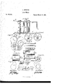
Figure 1 is a t0p 01 plan view 0f this invention. Figs. 2 and 3 are outside views 0f the sides 0r frame-work 0f the maehine. Figs. 4 am]. 5 are wheels 2u1d stud-plates upon which they am hung and by which they am adj usted t0 secure a proper elevation, :md allow it (the n1achine) so glide easily and freely over the ground. Fig'. 6 am the girts by mem1s of which the sides 01 frame-wo'rk are secured firmly together. Fig. 7 is a fixed 01 stationary straight-edge cutter-blade. Fig. .8, is a spi mlly-formed rotating cutter, hzwing the gear by whieh 113 is driven seeured upon 0ne end of its axis-bearings. Fig. 9 Shows 11110 groundroller which snpports the fmme-work, and from the revolutions of whiehmotion or a-otion is imp2uted to theworking mechanism 0f the machine. Fig. 10 shows a shaft having a gear seeured upon each eud thereof, f01 transmitfing motion from the ground-roller t0 the revolving cntter. Fig. 11 is a driving-gear 112W- ing a ratehet formed thereon, and in use is fitted closely und tnrns free1y up011 the shaft 0f the ground-roller. Fig. 13 is a flzmge-eolkm, which is fitted and secured firmly upon fl1e shaft 0f the ground-roller outside 0f and in elose proximity with the driving-gear h ving a spring-pawl device arranged. therein, which will allow the ground-roller to turn backward Without imparting moti on to the meehanism 0f the machine. lhe spring-pawl J can be so eonstrueted zus t0 be held away from the ratehet K at pleasure, so that the machine cm1 be run forward or backward with out turning the eutter. Fig. 12 shows the details of the pawl device, which is arranged in tl1e said flangecollar. This paw1 works in the notches of tl1e mcchet, and when tl1e maehine is pushed forward imparts motion t0 the whole workingmechanism of ol1e machine.
a, in Fig. 13, is aflange-collar, l1aving ahub, b, by means 0f which it is made fast upon the outer end of the shaft G in any common way. This flange is also provided With a chamber, c, to reeeive and allow a spiml spring, d, t0 work in and act upon the sprin g-pawl e. (Seen in Fig. 12.)
f is a boxing in which the pawl-lever g is arrzm'ged, and operates to hold the pawl 0 out of contaet with the ratchet-teebh k 011 gearwhee1 O This 1ever g is pivoted in boxingf a1; i, so that when it is thrown back, it (the spring-pawl 0,) will cont-raco spring d, and Wilhbe held out of contact with ratchet-teeth k 0n:jy gear-wheel O and is held out of contact by means of zu pin, h, inserted through the boxin f, whieh allows rollers H t0 revolve. freely in either direction without operating the mechanism whieh revolves the cutter; aud whenever it is desirable to operate the eutter, it is only neeessary to remove the pi11 h, when the spring-pa'wl e Will engage Wi ththe teeth k 011 gear-wheel C, and'the e1itter will again be made to revolve by pushing the machine forward.
Figs. 14 and 15 are caps which cover the boxing and the mechanism arranged therein, formed 011 t11e sides 01 fmme of the machine. Fig. 16 a1e oscillating arms, arranged upou the shaft 0f the ground-roller, und adjusted to their proper position by means 0f bolts 01 screws working through s1its formed. in the side 'frame-work, by mezms of whieh the operator pushes the machine before hi1n.
The sides 01 frame-work, as shown in Figs. 1 and 2, am design'ed t0 be 1nzmde 01' cast metal, hzwing the boxing A B to reeeive, c0ver, and protect the gears C D E F from bang; clogged or otherwise injured 01 rendered inopemoive by exposure. These geimrs 1nay be varied in Size, number 0f teeth, &c., t0 SGOH1'O oho.
desired numbor of revolutions of the revolving c11tter 2111(l tl1e easy working of tl1e 11121- ol1ine, and tl1e gea.r C may 1121ve its ratohetteetl1 oast o1 formecl thereon.
'Il1e orifioes 1 m1d 2 are macle having proper reference to suitable bearing-surface for the sl121tt G of tl1e roller I-I, es also tl1ose of 3 111d 4 for the sh:tft I.
Suitable g11ideways J are also formed 111 tl1e frame-work, 111 whiol1 the sliding z1cljustz1ble journal-boxes K 211*e fitted, so es to be mised 2111d lowored, a-s desirable, by means of setsorews L, for the purpose of adjusting the entting-edge of tl1e revolving outter M in olose proximity witl1 tl1e edge of the stationary autterQ. These journal-boxes K a1e fitted closely to tl1e w:1ys J, 2t1ld so as to be easily raised or lowered, as desirable, und hold firmly in the desired position by means of tl1e set-sorews L. They are also provided witl1 bearin gs 5 and 6, to receive the bea.rings of the revolving c11tter M.
I propose, in tl1e manufaoture of these 11121- el1ines, to 21112111g0 21 bla.de 11p011 21ml near the outer edges of the outter M, hzwing slits therei11 fo1 the passage of fastening a.11d adjusting bolts, for tl1e purpose of adjusting and chang- 1'ng them from timo to time, as desirable, to compensate fo1 Wem, breakage, &o.
N, o:1ps for oovering the boxesAl3, 2111d are secured thereon by sorews, so tha-t they 02111 l1e easily 111d quiokly removed 111d replaoed.
O are tootl1ed o1 raok surfaces formed 011 tl1e frzune-work, having slots O forn1ed therein for the reeeption and pl21y of fastenin g-l1olts P, the objeet of whioh is to adjust and finnly seoure r.l1e studs O also having teetl1 or raok-surfztces to fit the surfaoe O, ancl so es to be ez1sily adjustecl up o1 dow11 130 tl1e desired plaoe, 2111d hold firn1ly in the clesirecl osition by means of fastening-bolts P. These studs 0 a-re provicled with an ax1' s-piu, upon wl1ioh the wheels R are seoured. Tl1e object of these wheels is to hold ehe front portion of tl1e maohine z1t its proper heigl1t fron1 tl1e ground, ancl by being oonstruoted of larger diameter tl1a.11 ordinary guicle-wheels in lmvn-mowers, 111d so 21s to be adjusted :1t any required Position 011 tl1e m11- 0110 end of tl1e 211111s S is plaoed upon the I shaft of tl1e roller H, 111d is further secured to tl1e frame-work by sorews o1 bolts working througl1 the slots T formed in the frame-work. The outer ends of these handles are oouneeted by a. oross-bar, U.
I have thus endeavored to show in tl1e drztwings ancl speoification the nature 211111 tl1e 0011- struotion of this invention, so es to enable a person skilled in tl1e a1t to make und use tl1e Same therefrom.
What I ola-in1, therefore, 111d desire to secure by Letters Patent, is
l. The oombination of tl1e roller H, fianged oollar fast 011 shaft G, 'and having spring-pawl provided witl1 tl1e engaging and disengaging meol1anism desoribed, arranged therein,with tl1e ratohet-teeth on geztr-wheel C, whioh freely revolves upon sl1aft G, and g'1ves motion to the revolving outter through intermediato gearwheels, when all the parts are construoted and arrar,;ed to operate in tl1e 11121111101 21ml for the purpose desoribed.
2. 'll1e roller H on shaft G. having the flange- 0011211 and spring-pawl provided with tl1e engz1gin g and. disengaging mochanism desoribod, the ratohet-teeth 011 wheel C, inolosed gearwheels O D E F. and intermediate sl1aft, revolving a-dj ustable outter M, transverse outter Q, adjustable wheels R, and adjustable arms S, all construotecl a.nd arrangecl With relation to eaol1 other and. to the f1ame of tl1e machine, a-s herein desoribed.
JOSEPH ARBEITER.
Witnesses E. W. Bmss; JERE'MY W. Bmss.
Publications (1)
| Publication Number | Publication Date |
|---|---|
| US100840A true US100840A (en) | 1870-03-15 |
Family
ID=2170306
Family Applications (1)
| Application Number | Title | Priority Date | Filing Date |
|---|---|---|---|
| US100840D Expired - Lifetime US100840A (en) | Improvement in lawn-mowers |
Country Status (1)
| Country | Link |
|---|---|
| US (1) | US100840A (en) |
-
0
- US US100840D patent/US100840A/en not_active Expired - Lifetime
Similar Documents
| Publication | Publication Date | Title |
|---|---|---|
| US100840A (en) | Improvement in lawn-mowers | |
| US1214732A (en) | Card-display device. | |
| US116413A (en) | Improvement in friction-pawl or clutch mechanisms | |
| US427103A (en) | Gear-wheel | |
| US70059A (en) | Improvement in harvesters | |
| US110592A (en) | Improvement in lawn-mowers | |
| US106441A (en) | Improvement in rotary steam-plows | |
| US118333A (en) | Improvement in clutches for harvesters | |
| US103398A (en) | Improved gear-wheel | |
| US74481A (en) | akmstbokg | |
| US98348A (en) | Improvement in lawn-mowers | |
| US118810A (en) | Improvement in hay-tedders | |
| US88790A (en) | Improvement in corn-shellers | |
| US103397A (en) | Improved machine for rolling metals | |
| US112617A (en) | Improvement in potato-planters | |
| US100221A (en) | Improvement in gearing for harvesters | |
| US432057A (en) | Fourths to john m | |
| US77394A (en) | Improvement in gobi-harvesters | |
| US102975A (en) | Improvement in bending-machines | |
| US114867A (en) | Improvement in fruit-parers | |
| US98944A (en) | Improvement in corn-shellers | |
| US438231A (en) | kirkpatrick | |
| US104846A (en) | Improvement in corn-harvesters | |
| US108539A (en) | Improvement in adjustable gear-wheels | |
| US1014473A (en) | Corn-harvester. |