US10083981B2 - Memory arrays, and methods of forming memory arrays - Google Patents
Memory arrays, and methods of forming memory arrays Download PDFInfo
- Publication number
- US10083981B2 US10083981B2 US15/422,335 US201715422335A US10083981B2 US 10083981 B2 US10083981 B2 US 10083981B2 US 201715422335 A US201715422335 A US 201715422335A US 10083981 B2 US10083981 B2 US 10083981B2
- Authority
- US
- United States
- Prior art keywords
- levels
- regions
- charge
- along
- wordline
- Prior art date
- Legal status (The legal status is an assumption and is not a legal conclusion. Google has not performed a legal analysis and makes no representation as to the accuracy of the status listed.)
- Active
Links
- 238000000034 method Methods 0.000 title claims abstract description 24
- 238000003491 array Methods 0.000 title abstract description 8
- 239000000463 material Substances 0.000 claims abstract description 264
- 239000003989 dielectric material Substances 0.000 claims abstract description 27
- VYPSYNLAJGMNEJ-UHFFFAOYSA-N Silicium dioxide Chemical compound O=[Si]=O VYPSYNLAJGMNEJ-UHFFFAOYSA-N 0.000 claims description 30
- 229910052751 metal Inorganic materials 0.000 claims description 19
- 239000002184 metal Substances 0.000 claims description 19
- XUIMIQQOPSSXEZ-UHFFFAOYSA-N Silicon Chemical compound [Si] XUIMIQQOPSSXEZ-UHFFFAOYSA-N 0.000 claims description 17
- 229910052710 silicon Inorganic materials 0.000 claims description 16
- 239000010703 silicon Substances 0.000 claims description 16
- 235000012239 silicon dioxide Nutrition 0.000 claims description 15
- 239000000377 silicon dioxide Substances 0.000 claims description 15
- 229910052581 Si3N4 Inorganic materials 0.000 claims description 12
- HQVNEWCFYHHQES-UHFFFAOYSA-N silicon nitride Chemical compound N12[Si]34N5[Si]62N3[Si]51N64 HQVNEWCFYHHQES-UHFFFAOYSA-N 0.000 claims description 12
- QGZKDVFQNNGYKY-UHFFFAOYSA-N Ammonia Chemical compound N QGZKDVFQNNGYKY-UHFFFAOYSA-N 0.000 claims description 8
- 229910001925 ruthenium oxide Inorganic materials 0.000 claims description 5
- WOCIAKWEIIZHES-UHFFFAOYSA-N ruthenium(iv) oxide Chemical compound O=[Ru]=O WOCIAKWEIIZHES-UHFFFAOYSA-N 0.000 claims description 5
- 229910021529 ammonia Inorganic materials 0.000 claims description 4
- QJGQUHMNIGDVPM-UHFFFAOYSA-N nitrogen group Chemical group [N] QJGQUHMNIGDVPM-UHFFFAOYSA-N 0.000 claims description 4
- PXGOKWXKJXAPGV-UHFFFAOYSA-N Fluorine Chemical compound FF PXGOKWXKJXAPGV-UHFFFAOYSA-N 0.000 claims description 3
- 229910052731 fluorine Inorganic materials 0.000 claims description 3
- 239000011737 fluorine Substances 0.000 claims description 3
- 229910000449 hafnium oxide Inorganic materials 0.000 claims description 3
- WIHZLLGSGQNAGK-UHFFFAOYSA-N hafnium(4+);oxygen(2-) Chemical compound [O-2].[O-2].[Hf+4] WIHZLLGSGQNAGK-UHFFFAOYSA-N 0.000 claims description 3
- 239000001257 hydrogen Substances 0.000 claims description 3
- 229910052739 hydrogen Inorganic materials 0.000 claims description 3
- 125000004435 hydrogen atom Chemical class [H]* 0.000 claims description 3
- TWNQGVIAIRXVLR-UHFFFAOYSA-N oxo(oxoalumanyloxy)alumane Chemical compound O=[Al]O[Al]=O TWNQGVIAIRXVLR-UHFFFAOYSA-N 0.000 claims description 3
- BPUBBGLMJRNUCC-UHFFFAOYSA-N oxygen(2-);tantalum(5+) Chemical compound [O-2].[O-2].[O-2].[O-2].[O-2].[Ta+5].[Ta+5] BPUBBGLMJRNUCC-UHFFFAOYSA-N 0.000 claims description 3
- RVTZCBVAJQQJTK-UHFFFAOYSA-N oxygen(2-);zirconium(4+) Chemical compound [O-2].[O-2].[Zr+4] RVTZCBVAJQQJTK-UHFFFAOYSA-N 0.000 claims description 3
- 229910001936 tantalum oxide Inorganic materials 0.000 claims description 3
- 229910001928 zirconium oxide Inorganic materials 0.000 claims description 3
- 239000000203 mixture Substances 0.000 description 25
- 239000004020 conductor Substances 0.000 description 15
- 238000010276 construction Methods 0.000 description 7
- 239000004065 semiconductor Substances 0.000 description 7
- 238000013508 migration Methods 0.000 description 6
- 239000000758 substrate Substances 0.000 description 6
- -1 tungsten nitride Chemical class 0.000 description 6
- 230000005012 migration Effects 0.000 description 5
- IJGRMHOSHXDMSA-UHFFFAOYSA-N Atomic nitrogen Chemical compound N#N IJGRMHOSHXDMSA-UHFFFAOYSA-N 0.000 description 4
- 238000000231 atomic layer deposition Methods 0.000 description 4
- 238000005229 chemical vapour deposition Methods 0.000 description 4
- 238000012545 processing Methods 0.000 description 4
- WGTYBPLFGIVFAS-UHFFFAOYSA-M tetramethylammonium hydroxide Chemical compound [OH-].C[N+](C)(C)C WGTYBPLFGIVFAS-UHFFFAOYSA-M 0.000 description 4
- 230000004888 barrier function Effects 0.000 description 3
- 239000002800 charge carrier Substances 0.000 description 3
- 229910052732 germanium Inorganic materials 0.000 description 3
- GNPVGFCGXDBREM-UHFFFAOYSA-N germanium atom Chemical compound [Ge] GNPVGFCGXDBREM-UHFFFAOYSA-N 0.000 description 3
- 150000004767 nitrides Chemical class 0.000 description 3
- 230000008569 process Effects 0.000 description 3
- 229910052721 tungsten Inorganic materials 0.000 description 3
- 239000010937 tungsten Substances 0.000 description 3
- RTAQQCXQSZGOHL-UHFFFAOYSA-N Titanium Chemical compound [Ti] RTAQQCXQSZGOHL-UHFFFAOYSA-N 0.000 description 2
- 238000000429 assembly Methods 0.000 description 2
- 230000000712 assembly Effects 0.000 description 2
- 230000008901 benefit Effects 0.000 description 2
- 230000015572 biosynthetic process Effects 0.000 description 2
- 238000004891 communication Methods 0.000 description 2
- 230000006870 function Effects 0.000 description 2
- 230000014759 maintenance of location Effects 0.000 description 2
- 238000004519 manufacturing process Methods 0.000 description 2
- 150000002739 metals Chemical class 0.000 description 2
- 229910021421 monocrystalline silicon Inorganic materials 0.000 description 2
- 229910052757 nitrogen Inorganic materials 0.000 description 2
- 238000005240 physical vapour deposition Methods 0.000 description 2
- 229910021420 polycrystalline silicon Inorganic materials 0.000 description 2
- 229910021332 silicide Inorganic materials 0.000 description 2
- FVBUAEGBCNSCDD-UHFFFAOYSA-N silicide(4-) Chemical compound [Si-4] FVBUAEGBCNSCDD-UHFFFAOYSA-N 0.000 description 2
- 239000011232 storage material Substances 0.000 description 2
- 239000000126 substance Substances 0.000 description 2
- 229910052719 titanium Inorganic materials 0.000 description 2
- 239000010936 titanium Substances 0.000 description 2
- WFKWXMTUELFFGS-UHFFFAOYSA-N tungsten Chemical compound [W] WFKWXMTUELFFGS-UHFFFAOYSA-N 0.000 description 2
- 239000011800 void material Substances 0.000 description 2
- NRTOMJZYCJJWKI-UHFFFAOYSA-N Titanium nitride Chemical compound [Ti]#N NRTOMJZYCJJWKI-UHFFFAOYSA-N 0.000 description 1
- 229910021417 amorphous silicon Inorganic materials 0.000 description 1
- 238000007385 chemical modification Methods 0.000 description 1
- 238000013500 data storage Methods 0.000 description 1
- 230000009849 deactivation Effects 0.000 description 1
- 238000000151 deposition Methods 0.000 description 1
- 230000008021 deposition Effects 0.000 description 1
- 238000009792 diffusion process Methods 0.000 description 1
- 239000012634 fragment Substances 0.000 description 1
- 239000012212 insulator Substances 0.000 description 1
- 230000004048 modification Effects 0.000 description 1
- 238000012986 modification Methods 0.000 description 1
- NJPPVKZQTLUDBO-UHFFFAOYSA-N novaluron Chemical compound C1=C(Cl)C(OC(F)(F)C(OC(F)(F)F)F)=CC=C1NC(=O)NC(=O)C1=C(F)C=CC=C1F NJPPVKZQTLUDBO-UHFFFAOYSA-N 0.000 description 1
- 230000006911 nucleation Effects 0.000 description 1
- 238000010899 nucleation Methods 0.000 description 1
- 230000000704 physical effect Effects 0.000 description 1
- 229920005591 polysilicon Polymers 0.000 description 1
- 239000002243 precursor Substances 0.000 description 1
- 239000003870 refractory metal Substances 0.000 description 1
- 239000007787 solid Substances 0.000 description 1
Images


Classifications
-
- H01L27/11582—
-
- H—ELECTRICITY
- H10—SEMICONDUCTOR DEVICES; ELECTRIC SOLID-STATE DEVICES NOT OTHERWISE PROVIDED FOR
- H10B—ELECTRONIC MEMORY DEVICES
- H10B41/00—Electrically erasable-and-programmable ROM [EEPROM] devices comprising floating gates
- H10B41/10—Electrically erasable-and-programmable ROM [EEPROM] devices comprising floating gates characterised by the top-view layout
-
- H—ELECTRICITY
- H10—SEMICONDUCTOR DEVICES; ELECTRIC SOLID-STATE DEVICES NOT OTHERWISE PROVIDED FOR
- H10B—ELECTRONIC MEMORY DEVICES
- H10B43/00—EEPROM devices comprising charge-trapping gate insulators
- H10B43/20—EEPROM devices comprising charge-trapping gate insulators characterised by three-dimensional arrangements, e.g. with cells on different height levels
- H10B43/23—EEPROM devices comprising charge-trapping gate insulators characterised by three-dimensional arrangements, e.g. with cells on different height levels with source and drain on different levels, e.g. with sloping channels
- H10B43/27—EEPROM devices comprising charge-trapping gate insulators characterised by three-dimensional arrangements, e.g. with cells on different height levels with source and drain on different levels, e.g. with sloping channels the channels comprising vertical portions, e.g. U-shaped channels
-
- H01L21/28282—
-
- H01L27/1157—
-
- H—ELECTRICITY
- H01—ELECTRIC ELEMENTS
- H01L—SEMICONDUCTOR DEVICES NOT COVERED BY CLASS H10
- H01L29/00—Semiconductor devices adapted for rectifying, amplifying, oscillating or switching, or capacitors or resistors with at least one potential-jump barrier or surface barrier, e.g. PN junction depletion layer or carrier concentration layer; Details of semiconductor bodies or of electrodes thereof ; Multistep manufacturing processes therefor
- H01L29/02—Semiconductor bodies ; Multistep manufacturing processes therefor
- H01L29/06—Semiconductor bodies ; Multistep manufacturing processes therefor characterised by their shape; characterised by the shapes, relative sizes, or dispositions of the semiconductor regions ; characterised by the concentration or distribution of impurities within semiconductor regions
- H01L29/10—Semiconductor bodies ; Multistep manufacturing processes therefor characterised by their shape; characterised by the shapes, relative sizes, or dispositions of the semiconductor regions ; characterised by the concentration or distribution of impurities within semiconductor regions with semiconductor regions connected to an electrode not carrying current to be rectified, amplified or switched and such electrode being part of a semiconductor device which comprises three or more electrodes
- H01L29/1025—Channel region of field-effect devices
- H01L29/1029—Channel region of field-effect devices of field-effect transistors
- H01L29/1033—Channel region of field-effect devices of field-effect transistors with insulated gate, e.g. characterised by the length, the width, the geometric contour or the doping structure
- H01L29/1037—Channel region of field-effect devices of field-effect transistors with insulated gate, e.g. characterised by the length, the width, the geometric contour or the doping structure and non-planar channel
-
- H—ELECTRICITY
- H01—ELECTRIC ELEMENTS
- H01L—SEMICONDUCTOR DEVICES NOT COVERED BY CLASS H10
- H01L29/00—Semiconductor devices adapted for rectifying, amplifying, oscillating or switching, or capacitors or resistors with at least one potential-jump barrier or surface barrier, e.g. PN junction depletion layer or carrier concentration layer; Details of semiconductor bodies or of electrodes thereof ; Multistep manufacturing processes therefor
- H01L29/40—Electrodes ; Multistep manufacturing processes therefor
- H01L29/401—Multistep manufacturing processes
- H01L29/4011—Multistep manufacturing processes for data storage electrodes
- H01L29/40117—Multistep manufacturing processes for data storage electrodes the electrodes comprising a charge-trapping insulator
-
- H—ELECTRICITY
- H01—ELECTRIC ELEMENTS
- H01L—SEMICONDUCTOR DEVICES NOT COVERED BY CLASS H10
- H01L29/00—Semiconductor devices adapted for rectifying, amplifying, oscillating or switching, or capacitors or resistors with at least one potential-jump barrier or surface barrier, e.g. PN junction depletion layer or carrier concentration layer; Details of semiconductor bodies or of electrodes thereof ; Multistep manufacturing processes therefor
- H01L29/40—Electrodes ; Multistep manufacturing processes therefor
- H01L29/41—Electrodes ; Multistep manufacturing processes therefor characterised by their shape, relative sizes or dispositions
- H01L29/423—Electrodes ; Multistep manufacturing processes therefor characterised by their shape, relative sizes or dispositions not carrying the current to be rectified, amplified or switched
- H01L29/42312—Gate electrodes for field effect devices
- H01L29/42316—Gate electrodes for field effect devices for field-effect transistors
- H01L29/4232—Gate electrodes for field effect devices for field-effect transistors with insulated gate
- H01L29/4234—Gate electrodes for transistors with charge trapping gate insulator
-
- H—ELECTRICITY
- H01—ELECTRIC ELEMENTS
- H01L—SEMICONDUCTOR DEVICES NOT COVERED BY CLASS H10
- H01L29/00—Semiconductor devices adapted for rectifying, amplifying, oscillating or switching, or capacitors or resistors with at least one potential-jump barrier or surface barrier, e.g. PN junction depletion layer or carrier concentration layer; Details of semiconductor bodies or of electrodes thereof ; Multistep manufacturing processes therefor
- H01L29/66—Types of semiconductor device ; Multistep manufacturing processes therefor
- H01L29/68—Types of semiconductor device ; Multistep manufacturing processes therefor controllable by only the electric current supplied, or only the electric potential applied, to an electrode which does not carry the current to be rectified, amplified or switched
- H01L29/76—Unipolar devices, e.g. field effect transistors
- H01L29/772—Field effect transistors
- H01L29/78—Field effect transistors with field effect produced by an insulated gate
- H01L29/792—Field effect transistors with field effect produced by an insulated gate with charge trapping gate insulator, e.g. MNOS-memory transistors
- H01L29/7926—Vertical transistors, i.e. transistors having source and drain not in the same horizontal plane
-
- H—ELECTRICITY
- H10—SEMICONDUCTOR DEVICES; ELECTRIC SOLID-STATE DEVICES NOT OTHERWISE PROVIDED FOR
- H10B—ELECTRONIC MEMORY DEVICES
- H10B41/00—Electrically erasable-and-programmable ROM [EEPROM] devices comprising floating gates
- H10B41/30—Electrically erasable-and-programmable ROM [EEPROM] devices comprising floating gates characterised by the memory core region
- H10B41/35—Electrically erasable-and-programmable ROM [EEPROM] devices comprising floating gates characterised by the memory core region with a cell select transistor, e.g. NAND
-
- H—ELECTRICITY
- H10—SEMICONDUCTOR DEVICES; ELECTRIC SOLID-STATE DEVICES NOT OTHERWISE PROVIDED FOR
- H10B—ELECTRONIC MEMORY DEVICES
- H10B41/00—Electrically erasable-and-programmable ROM [EEPROM] devices comprising floating gates
- H10B41/40—Electrically erasable-and-programmable ROM [EEPROM] devices comprising floating gates characterised by the peripheral circuit region
- H10B41/41—Electrically erasable-and-programmable ROM [EEPROM] devices comprising floating gates characterised by the peripheral circuit region of a memory region comprising a cell select transistor, e.g. NAND
-
- H—ELECTRICITY
- H10—SEMICONDUCTOR DEVICES; ELECTRIC SOLID-STATE DEVICES NOT OTHERWISE PROVIDED FOR
- H10B—ELECTRONIC MEMORY DEVICES
- H10B43/00—EEPROM devices comprising charge-trapping gate insulators
- H10B43/10—EEPROM devices comprising charge-trapping gate insulators characterised by the top-view layout
-
- H—ELECTRICITY
- H10—SEMICONDUCTOR DEVICES; ELECTRIC SOLID-STATE DEVICES NOT OTHERWISE PROVIDED FOR
- H10B—ELECTRONIC MEMORY DEVICES
- H10B43/00—EEPROM devices comprising charge-trapping gate insulators
- H10B43/30—EEPROM devices comprising charge-trapping gate insulators characterised by the memory core region
- H10B43/35—EEPROM devices comprising charge-trapping gate insulators characterised by the memory core region with cell select transistors, e.g. NAND
Definitions
- Memory arrays and methods of forming memory arrays.
- Flash memory provides data storage for electronic systems. Flash memory is one type of memory, and has numerous uses in modern computers and devices. For instance, modern personal computers may have BIOS stored on a flash memory chip. As another example, it is becoming increasingly common for computers and other devices to utilize flash memory in solid state drives to replace conventional hard drives. As yet another example, flash memory is popular in wireless electronic devices because it enables manufacturers to support new communication protocols as they become standardized, and to provide the ability to remotely upgrade the devices for enhanced features.
- NAND may be a basic architecture of integrated flash memory.
- a NAND cell unit comprises at least one selecting device coupled in series to a serial combination of memory cells (with the serial combination commonly being referred to as a NAND string).
- NAND architecture may be configured in a three-dimensional arrangement comprising vertically-stacked memory cells. It is desired to develop improved NAND architecture.
- FIG. 1 is a diagrammatic cross-sectional side view of an example integrated structure having a region of an example NAND memory array.
- FIG. 2 is a diagrammatic cross-sectional side view of another example integrated structure having a region of another example NAND memory array.
- FIGS. 3-10 are diagrammatic cross-sectional side views of an example integrated structure at process stages of an example method.
- FIGS. 11-14 are diagrammatic cross-sectional side views of an example integrated structure at process stages of an example method.
- the process stage of FIG. 11 may follow that of FIG. 9 .
- Operation of NAND memory cells may comprise movement of charge between a channel material and a charge-trapping material.
- programming of a NAND memory cell may comprise moving charge (i.e., electrons) from the channel material into the charge-trapping material, and then storing the charge within the charge-trapping material.
- Erasing of the NAND memory cell may comprise moving holes into the charge-trapping material to recombine with electrons stored in the charge-trapping material, and thereby release charge from the charge-trapping material.
- the charge-trapping material may comprise, for example, silicon nitride, silicon oxynitride, ruthenium oxide, etc.
- a problem with conventional NAND can be that charge-trapping material extends across multiple memory cells of a memory array, and can enable charge migration between the cells.
- the charge migration between memory cells may lead to data retention problems.
- Some embodiments include structures which impede migration of charge between memory cells.
- the structures utilized to impede charge migration may be breaks in the charge-trapping material in regions between memory cells.
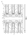
- FIG. 1 a portion of an integrated structure 10 is illustrated, with such portion including a fragment of a three-dimensional NAND memory array 12 .
- the integrated structure 10 comprises a stack 15 of alternating first and second levels 18 and 20 .
- the levels 18 are insulative (i.e. dielectric), and the levels 20 are conductive.
- the insulative levels 18 comprise insulative material 26 .
- Such insulative material may comprise any suitable composition or combination of compositions; and may, for example, comprise silicon dioxide.
- the conductive levels 20 comprise conductive materials 28 and 30 .
- the conductive material 28 may be considered to be a conductive core, and the conductive material 30 may be considered to be an outer conductive layer surrounding the conductive core.
- the conductive materials 28 and 30 may comprise different compositions than one another.
- the conductive material 28 may comprise, consist essentially of, or consist of one or more metals (for instance, tungsten, titanium, etc.)
- the conductive material 30 may comprise, consist essentially of, or consist of one or more metal-containing compositions (for instance, metal nitride, metal silicide, metal carbide, etc.).
- the conductive material 30 may comprise, consist essentially of, or consist of one or more metal nitrides (for instance, titanium nitride, tungsten nitride, etc.).
- the materials 28 / 30 illustrate an example configuration of the conductive levels 20 .
- the conductive levels 20 may comprise other configurations of conductive material; and may, for example, comprise a single conductive material or more than the illustrated two conductive materials.
- the conductive levels 20 may comprise conductive material having any suitable composition or combination of compositions; and may comprise, for example, one or more of various metals (for example, tungsten, titanium, etc.), metal-containing compositions (for example, metal nitride, metal carbide, metal silicide, etc.), and conductively-doped semiconductor materials (for example, conductively-doped silicon, conductively-doped germanium, etc.).
- Insulative material 32 forms an insulative liner surrounding the outer conductive layer of material 30 .
- the insulative material 32 may comprise high-k material (for instance, one or more of aluminum oxide, hafnium oxide, zirconium oxide, tantalum oxide, etc.); where the term “high-k” means a dielectric constant greater than that of silicon dioxide.
- high-k means a dielectric constant greater than that of silicon dioxide.
- the insulative material 32 is shown to be a single homogenous material, in other embodiments the insulative material may comprise two or more discrete compositions.
- the insulative material 32 may comprise a laminate of silicon dioxide and one or more high-k materials.
- the conductive levels 20 may be considered to be wordline levels of a NAND memory array. Terminal ends 34 of the wordline levels 20 may function as control gate regions 35 of NAND memory cells 36 , with approximate locations of the memory cells 36 being indicated with brackets in FIG. 1 .
- the conductive levels 20 and insulative levels 18 may be of any suitable vertical thicknesses. In some embodiments, the conductive levels 20 and the insulative levels 18 may have vertical thicknesses within a range of from about 10 nanometers (nm) to about 300 nm. In some embodiments, the conductive levels 20 may have about the same vertical thicknesses as the insulative levels 18 . In other embodiments, the conductive levels 20 may have substantially different vertical thicknesses than the insulative levels 18 .
- the vertically-stacked memory cells 36 form a vertical string (such as, for example, a vertical NAND string of memory cells), with the number of memory cells in each string being determined by the number of conductive levels 20 .
- the stack may comprise any suitable number of conductive levels. For instance, the stack may have 8 conductive levels, 16 conductive levels, 32 conductive levels, 64 conductive levels, 512 conductive levels, 1028 conductive levels, etc.
- the insulative materials 26 and 32 may be considered to form sidewalls 38 of an opening 40 extending through stack 15 .
- the opening 40 may have a continuous shape when viewed from above; and may be, for example, circular, elliptical, etc. Accordingly, the sidewalls 38 of FIG. 1 may be comprised by a continuous sidewall that extends around the periphery of opening 40 .
- the insulative material 32 may be considered to be a charge-blocking material, with regions of such charge-blocking material 32 extending along the terminal ends 34 of wordline levels 20 .
- a charge-blocking material may have the following functions in a memory cell: in a program mode, the charge-blocking material may prevent charge carriers from passing out of the charge-storage material (e.g., floating-gate material, charge-trapping material, etc.) toward the control gate; and in an erase mode, the charge-blocking material may prevent charge carriers from flowing into the charge-storage material from the control gate.
- the charge-storage material e.g., floating-gate material, charge-trapping material, etc.
- Charge-trapping material 44 extends along the terminal ends 34 (i.e., control gate regions 35 ) of wordline levels 20 , and is spaced from the control gate regions by the charge-blocking material 32 .
- the charge-trapping material 44 may comprise any suitable composition or combination of compositions; and in some embodiments, may comprise one or more of silicon nitride, silicon oxynitride, ruthenium oxide, etc.
- the charge-trapping material 44 may comprise, consist essentially of, or consist of material comprising silicon and nitrogen.
- a “charge trap” refers to an energy well that can reversibly capture a charge carrier (e.g., an electron or hole).
- the charge-trapping material 44 is provided in segments 43 which are arranged one atop another (i.e., are vertically stacked), and which are vertically spaced from one another by gaps 45 .
- Each of the segments 43 of the charge-trapping material 44 is adjacent a wordline level 20
- each of the gaps 45 is adjacent one of the insulative levels 18 .
- the segments 43 of charge-trapping material 44 do not extend vertically beyond the wordline levels 20 (i.e., do not vertically overlap the insulative levels 18 ).
- the segments 43 of charge-trapping material 44 may extend vertically beyond the conductive levels 20 to partially overlap the insulative levels 18 .
- the gaps 45 may be referred to as intervening regions which block charge migration between the segments 43 of charge-trapping material 44 . Such prevents charge from migrating between vertically-adjacent memory cells 36 .
- conventional three-dimensional NAND memory arrays may have a continuous layer of charge-trapping material extending along all of the vertically-stacked memory cells of a NAND string, and such may undesirably enable charge-migration between the memory cells of the string and lead to data loss.
- the embodiment of FIG. 1 may have improved data retention as compared to such conventional three-dimensional NAND memory arrays.
- Charge-tunneling material 46 extends vertically along the charge-trapping material 44 , and extends into the gaps 45 .
- the charge-tunneling material 46 may comprise any suitable composition or combination of compositions; and in some embodiments may comprise, consist essentially of, or consist of a bandgap-engineered structure having nitrogen-containing material laterally sandwiched between two oxides.
- the nitrogen-containing material may be, for example, silicon nitride.
- the two oxides may be the same composition as one another, or may comprise different compositions relative to one another; and in some embodiments may both be silicon dioxide.
- the charge-tunneling material 46 may be considered to comprise gate-dielectric material in some embodiments.
- the charge-tunneling material 46 may comprise, consist essentially of, or consist of silicon dioxide in some embodiments. In operation, charge may tunnel through the charge-tunneling material 46 as charge is transferred between the charge-trapping material 44 and channel material (material 48 , which is described below) of the memory cells 36 during programming operations, erasing operations, etc. In some embodiments, the charge-tunneling material 46 may be referred to simply as an insulative material or as a dielectric material.
- the charge-tunneling material 46 is referred to as “extending vertically” to indicate that it generally extends through the stack 15 .
- the vertically-extending material 46 (and other materials described herein as extending vertically) may extend substantially orthogonally relative to upper surfaces of the levels 18 and 20 (as shown), or not; depending on, for example, whether opening 40 has sidewalls which are substantially orthogonal to the upper surfaces of the levels 18 and 20 , or not.
- the charge-tunneling material 46 is within the gaps 45 between the segments 43 of charge-trapping material 44 .
- the charge-trapping material 44 may be considered to be configured as a linear arrangement which extends vertically along the stack 15 ; with such linear arrangement comprising the segments 43 of charge-trapping material 44 alternating with segments 47 of charge-tunneling material 46 .
- the charge-tunneling material 46 within gaps 45 may be referred to as spacing material between the segments 43 .
- the charge-tunneling material 46 is shown having regions which extend into the gaps 45 to form the segments 47 (i.e., to form the spacing material between segments 43 ), in other embodiments other insulative material may be within the gaps 45 and utilized as the spacing material between the segments 43 . In such embodiments, the charge-tunneling material 46 may extend along such other insulative material, rather than extending into the gaps 45 .
- Channel material 48 extends vertically along the charge-tunneling material 46 (and, in some embodiments may be considered to extend vertically along the stack 15 ).
- the charge-tunneling material 46 is laterally between the channel material 48 and the charge-trapping material 44 .
- the channel material 48 may comprise any suitable composition or combination of compositions; and in some embodiments may comprise, consist essentially of, or consist of appropriately-doped silicon.
- an insulative region 50 extends along a middle of opening 40 .
- the insulative region 50 may comprise any suitable insulative composition; including, for example, silicon dioxide, silicon nitride, etc. Alternatively, at least a portion of the insulative region 50 may be a void.
- the illustrated embodiment having the insulative region 50 extending down the middle of opening 40 is a so-called hollow-channel configuration. In other embodiments, the channel material 48 may entirely fill the central region of opening 40 to form a vertically-extending pedestal within such central region.
- the stack 15 is supported by a base 52 .
- a break is provided between the base 52 and the stack 15 to indicate that there may be additional materials and/or integrated circuit structures between the base 52 and the stack 15 .
- additional integrated materials may include, for example, source-side select gate material (SGS material).
- the base 52 may comprise semiconductor material; and may, for example, comprise, consist essentially of, or consist of monocrystalline silicon.
- the base 52 may be referred to as a semiconductor substrate.
- semiconductor substrate means any construction comprising semiconductive material, including, but not limited to, bulk semiconductive materials such as a semiconductive wafer (either alone or in assemblies comprising other materials), and semiconductive material layers (either alone or in assemblies comprising other materials).
- substrate refers to any supporting structure, including, but not limited to, the semiconductor substrates described above.
- the base 52 may correspond to a semiconductor substrate containing one or more materials associated with integrated circuit fabrication. Such materials may include, for example, one or more of refractory metal materials, barrier materials, diffusion materials, insulator materials, etc.
- FIG. 2 shows a construction 10 a having a NAND memory array 12 a illustrating another example configuration.
- the configuration of FIG. 2 is similar to that of FIG. 1 , except that the insulative material 32 (i.e., the charge-blocking material) is only along terminal regions 53 of the wordline levels 20 .
- each of the wordline levels 20 has a first region 51 (i.e., a non-terminal region) laterally adjacent a second region 53 (i.e., a terminal region), with the first regions 51 being vertically thicker than the second regions 53 .
- the insulative material 32 extends along a top and a bottom of each of the terminal regions 53 of the wordline levels 20 , but is not along either the top or the bottom of each of the non-terminal regions 51 of the wordline levels 20 .
- the non-terminal regions 51 of the wordline levels 20 have vertical thicknesses T 1
- the terminal regions 53 of the wordline levels 20 have vertical thicknesses T 2 .
- the vertical thickness T 2 is less than the vertical thickness T 1 by about double a thickness of the insulative material 32 .
- the insulative material 32 may have any suitable thickness, and in some embodiments may have a thickness within a range of from about 5 nm to about 50 nm; and accordingly, in some embodiments the vertical thickness T 2 may less than the vertical thickness T 1 by a dimension within a range of from about 10 nm to about 100 nm.
- the embodiment of FIG. 2 may be advantageous relative to that of FIG. 1 in some applications, as the thick non-terminal regions 51 of the wordline levels 20 may enable the wordline levels to have lower resistance.
- the embodiment of FIG. 1 may be advantageous relative to that of FIG. 2 in some applications, as the embodiment of FIG. 1 may be fabricated with fewer process steps than that of FIG. 2 .
- FIGS. 1 and 2 may be fabricated utilizing any suitable methodology.
- Example methodology is described with reference to FIGS. 3-14 .
- a first example embodiment method is described with reference to FIGS. 3-10 .
- a construction 10 b is formed to include a vertical stack 60 of alternating first levels 62 and second levels 64 over the base 52 .
- the first levels 62 comprise first material 66
- the second levels 64 comprise second material 68 .
- the first and second materials 66 and 68 may comprise any suitable compositions or combinations of compositions.
- charge-trapping material 44 is selectively formed along the second material 68 relative to the first material 66 .
- the first material 66 comprises silicon dioxide, and accordingly may comprise the same material 26 as the insulative levels 18 of FIGS. 1 and 2 ; and the second material 68 comprises semiconductor material (for instance, silicon, germanium, etc.).
- the first material 66 comprises, consists essentially of, or consists of silicon dioxide; and the second material 68 comprises, consists essentially of, or consists of silicon (for instance, polycrystalline silicon, amorphous silicon, monocrystalline silicon, etc.).
- the opening 40 is formed to extend through stack 60 .
- the opening 40 may be formed utilizing any suitable methodology. For instance, a patterned mask (not shown) may be formed over the stack 60 to define a location of the opening 40 , and then the opening 40 may be formed to extend through the stack 60 with one or more suitable etches. Subsequently, the patterned mask may be removed.
- the opening 40 has sidewalls 65 extending along the first and second materials 66 and 68 .
- the first levels 62 have first surfaces 67 exposed along the sidewalls 65
- the second levels 64 have second surfaces 69 exposed along the sidewalls 65 .
- treatment material “X” is flowed into opening 40 .
- the treatment material “X” forms altered regions 70 (indicated diagrammatically with dashed lines) along the exposed surfaces 69 of the second material 68 of the second levels 64 .
- the second material 68 comprises silicon
- the treatment material “X” comprises one or more of the hydrogen, ammonia and fluorine.
- the altered regions 70 may be regions in which native oxide is disrupted along surfaces 69 , or entirely removed from the surfaces 69 .
- charge-trapping material 44 is selectively formed along the treated surfaces 69 relative to the surfaces 67 .
- the charge-trapping material 44 may comprise any suitable composition, and in some embodiments may comprise one or more of silicon nitride, silicon oxynitride and ruthenium oxide.
- the charge-trapping material comprises, consists essentially of, or consists of silicon nitride, and is selectively formed on treated surfaces 69 relative to surfaces 67 utilizing atomic layer deposition (ALD), and/or chemical vapor deposition (CVD), and/or any other suitable methods.
- ALD atomic layer deposition
- CVD chemical vapor deposition
- the silicon nitride of charge-trapping material 44 may be formed by reacting nitrogen-containing precursor (i.e., nitrogen, or a nitrogen-containing compound, such as, for example, ammonia) with silicon atoms of surface 69 at an appropriate temperature (for instance, a temperature in excess of about 900° C.).
- nitrogen-containing precursor i.e., nitrogen, or a nitrogen-containing compound, such as, for example, ammonia
- the charge-trapping material 44 may be formed to any suitable thickness, such as, for example, a thickness within a range of from about 5 nm to about 10 nm.
- FIGS. 5 and 6 activates surfaces of material 68 to induce selective formation of charge-trapping material 44 onto surfaces of material 68 relative to surfaces of material 66 .
- Alternative or additional processing may include deactivation of surfaces of material 66 .
- a barrier may be formed along surfaces of material 66 (for instance, by one or more of deposition of barrier material along surfaces 66 , by chemical modification of the surfaces of material 66 , by physical modification of the surfaces of material 66 , etc.) to impede or preclude formation of charge-trapping material 44 along the surfaces of material 66 .
- the charge-trapping material 44 forms the vertically-spaced segments 43 .
- Gaps 45 are along regions of material 66 between such vertically-spaced segments.
- charge-tunneling material 46 is formed to extend vertically along the first and second levels 62 / 64 .
- the charge-tunneling material is along the charge-trapping material 44 (and is spaced from the material 68 of the second levels 64 by the charge-trapping material 44 ), and extends into the gaps 45 .
- Channel material 48 is formed to extend vertically along the charge-tunneling material 46 .
- Insulative material 74 is formed within a remaining central region of opening 40 .
- the insulative material 74 forms the insulative region 50 described above with reference to FIG. 1 ; and may comprise any suitable composition or combination of compositions (such as, for example, silicon nitride, silicon dioxide, etc.).
- the insulative material 74 may be omitted and a void may be left within the central region of opening 40 .
- channel material 48 may be formed to entirely fill the opening 40 .
- the second material 68 ( FIG. 7 ) is removed to leave voids 80 .
- Such removal may be accomplished with any suitable etch which is selective for the second material 68 relative to the materials 44 and 66 .
- the etch may utilize tetramethylammonium hydroxide (TMAH).
- TMAH tetramethylammonium hydroxide
- slits may be formed through stack 60 ( FIG. 7 ) to provide access to the first and second levels 62 / 64 ( FIG. 7 ). Etchant may be flowed into such slits to access the second material 68 ( FIG. 7 ).
- insulative material 32 is formed within voids 80 to line the voids, and thereby become an insulative liner within the voids.
- the insulative material 32 may comprise high-k material (for instance, one or more of aluminum oxide, hafnium oxide, zirconium oxide, tantalum oxide, etc.) as discussed above with reference to FIG. 1 , and may be referred to as a charge-blocking material.
- conductive material 30 is formed within the lined voids 80 ( FIG. 9 ), and then conductive material 28 is formed within the lined voids 80 ( FIG. 9 ).
- the conductive material 28 may be considered to be a conductive core (as discussed above with reference to FIG. 1 ), and the conductive material 30 may be considered to be an outer conductive layer surrounding the conductive core (as is also discussed above with reference to FIG. 1 ).
- the construction 10 b of FIG. 10 comprises a NAND memory array 12 b analogous to the NAND memory array 12 discussed above with reference to FIG. 1 .
- the first material 66 may be the same as material 26 (e.g., may comprise silicon dioxide or other suitable insulative material) in some embodiments. Alternatively, the first material 66 may be removed and replaced with material 26 in some embodiments.
- the insulative material 32 is shown extending along edges of insulative levels 18 in the shown embodiment of FIGS. 9 and 10 , as may occur if the illustrated edges of insulative levels 18 are along a slit through which the insulative material 32 is deposited.
- a second example embodiment method of fabricating a NAND memory array is described with reference to FIGS. 11-14 .
- a construction 10 c is shown at a processing stage following that of FIG. 9 .
- the construction 10 c is shown after the voids 80 ( FIG. 9 ) are lined with insulative material 32 . Subsequently, sacrificial material 82 is formed within the lined voids.
- the sacrificial material 80 may comprise any suitable composition or combination of compositions, such as, for example, silicon, germanium, etc.
- the materials 82 and 32 are recessed to form cavities 84 .
- regions that had been in voids 80 may be considered to comprise first segments 85 and second segments 87 (labeled relative to regions in only one of the voids 80 in order to simplify the drawing).
- the first segments 85 are not lined with material 32
- the second segments 87 remain lined with the insulative material 32 .
- the conductive levels 20 are formed, and in the shown embodiment the conductive levels 20 comprise the materials 28 and 30 .
- the conductive levels 20 have the non-terminal regions 51 within the first segments 85 , and have the terminal regions 53 within the second segments 87 .
- the non-terminal regions 51 have the vertical thicknesses T 1
- the terminal regions 53 have the vertical thicknesses T 2 , analogous to the embodiment described above with reference to FIG. 2 .
- the construction 10 c of FIG. 14 comprises a NAND memory array 12 b analogous to the NAND memory array 12 b discussed above with reference to FIG. 2 .
- the first material 66 may be the same as material 26 (e.g., may comprise silicon dioxide or other suitable insulative material) in some embodiments. Alternatively, the first material 66 may be removed and replaced with material 26 in some embodiments.
- the structures and arrays described above may be incorporated into electronic systems.
- Such electronic systems may be used in, for example, memory modules, device drivers, power modules, communication modems, processor modules, and application-specific modules, and may include multilayer, multichip modules.
- the electronic systems may be any of a broad range of systems, such as, for example, cameras, wireless devices, displays, chip sets, set top boxes, games, lighting, vehicles, clocks, televisions, cell phones, personal computers, automobiles, industrial control systems, aircraft, etc.
- the various materials, substances, compositions, etc. described herein may be formed with any suitable methodologies, either now known or yet to be developed, including, for example, atomic layer deposition (ALD), chemical vapor deposition (CVD), physical vapor deposition (PVD), etc.
- ALD atomic layer deposition
- CVD chemical vapor deposition
- PVD physical vapor deposition
- dielectric dielectric
- electrically insulative dielectrically insulative
- the terms are considered synonymous in this disclosure.
- the utilization of the term “dielectric” in some instances, and the term “electrically insulative” in other instances, may be to provide language variation within this disclosure to simplify antecedent basis within the claims that follow, and is not utilized to indicate any significant chemical or electrical differences.
- Structures may be referred to as “extending vertically” to indicate that the structures generally extend upwardly from an underlying base (e.g., substrate).
- the vertically-extending structures may extend substantially orthogonally relative to an upper surface of the base, or not.
- Some embodiments include a memory array which includes a vertical stack of alternating insulative levels and wordline levels.
- the wordline levels have terminal ends corresponding to control gate regions.
- Charge-trapping material is along the control gate regions of the wordline levels and not along the insulative levels.
- the charge-trapping material is spaced from the control gate regions by charge-blocking material.
- Channel material extends vertically along the stack and is laterally spaced from the charge-trapping material by dielectric material.
- Some embodiments include a memory array comprising a vertical stack of alternating insulative levels and wordline levels.
- the wordline levels have terminal ends corresponding to control gate regions.
- a linear arrangement of charge-trapping material extends vertically along the stack.
- the linear arrangement of the charge-trapping material comprises vertically alternating segments of the charge-trapping material and segments of spacing material.
- the segments of charge-trapping material are along the wordline levels.
- Channel material extends vertically along the stack and is laterally spaced from the segments of the charge-trapping material by dielectric material.
- Some embodiments include a NAND memory array comprising a vertical stack of alternating insulative levels and wordline levels.
- the wordline levels have terminal ends corresponding to control gate regions.
- Charge-trapping material is along the control gate regions of the wordline levels, and is spaced from the control gate regions by charge-blocking material.
- the charge-trapping material is configured as segments, with each of the wordline levels being adjacent one of the segments of the charge-trapping material.
- the segments of the charge-trapping material are arranged one atop another and are vertically spaced from one another by intervening gaps.
- the wordline levels have first regions and second regions laterally adjacent the first regions. The first regions are vertically thicker than the second regions.
- the second regions comprise the terminal ends.
- Channel material extends vertically along the stack and is laterally spaced from the charge-trapping material by charge-tunneling material.
- Some embodiments include a method of forming a NAND memory array.
- a vertical stack of alternating first and second levels is formed.
- the first levels comprise first material
- the second levels comprise second material.
- the first and second levels have exposed surfaces along an opening extending through the first and second levels.
- Charge-trapping material is selectively formed along the exposed surfaces of the second levels relative to the exposed surfaces of the first levels.
- Charge-tunneling material is formed to extend vertically along the first and second levels, and is spaced from the second levels by the charge-trapping material.
- Channel material is formed to extend vertically along the charge-tunneling material.
- the second material is removed to leave voids.
- Conductive levels are formed within the voids.
- the conductive levels are wordline levels of the NAND memory array and have terminal ends corresponding to control gate regions.
- Some embodiments include a method of forming a NAND memory array.
- a vertical stack of alternating first and second levels is formed.
- the first levels comprise silicon dioxide, and the second levels comprise silicon.
- the first and second levels have exposed surfaces along an opening extending through the first and second levels.
- the exposed surfaces of the second levels are treated with one or more of hydrogen, ammonia and fluorine.
- Charge-trapping material is selectively formed along the treated surfaces of the second levels relative to the exposed surfaces of the first levels.
- Charge-tunneling material is formed to extend vertically along the first and second levels, and is spaced from the second levels by the charge-trapping material.
- Channel material is formed to extend vertically along the charge-tunneling material.
- the silicon of the second levels is removed to leave voids.
- Metal-containing conductive levels are formed within the voids.
- the metal-containing conductive levels are wordline levels of the NAND memory array and have terminal ends corresponding to control gate regions.
Abstract
Description
Claims (17)
Priority Applications (8)
| Application Number | Priority Date | Filing Date | Title |
|---|---|---|---|
| US15/422,335 US10083981B2 (en) | 2017-02-01 | 2017-02-01 | Memory arrays, and methods of forming memory arrays |
| EP18748728.5A EP3577688A4 (en) | 2017-02-01 | 2018-02-01 | Memory arrays, and methods of forming memory arrays |
| KR1020197024996A KR102332432B1 (en) | 2017-02-01 | 2018-02-01 | Memory Arrays, and Methods of Forming Memory Arrays |
| JP2019541107A JP6859443B2 (en) | 2017-02-01 | 2018-02-01 | Memory Array and How to Form a Memory Array |
| CN201880009394.3A CN110235246A (en) | 2017-02-01 | 2018-02-01 | Memory array and the method for forming memory array |
| PCT/US2018/016468 WO2018144743A1 (en) | 2017-02-01 | 2018-02-01 | Memory arrays, and methods of forming memory arrays |
| US16/031,919 US10304853B2 (en) | 2017-02-01 | 2018-07-10 | Memory arrays, and methods of forming memory arrays |
| US16/410,973 US10541252B2 (en) | 2017-02-01 | 2019-05-13 | Memory arrays, and methods of forming memory arrays |
Applications Claiming Priority (1)
| Application Number | Priority Date | Filing Date | Title |
|---|---|---|---|
| US15/422,335 US10083981B2 (en) | 2017-02-01 | 2017-02-01 | Memory arrays, and methods of forming memory arrays |
Related Child Applications (1)
| Application Number | Title | Priority Date | Filing Date |
|---|---|---|---|
| US16/031,919 Continuation US10304853B2 (en) | 2017-02-01 | 2018-07-10 | Memory arrays, and methods of forming memory arrays |
Publications (2)
| Publication Number | Publication Date |
|---|---|
| US20180219021A1 US20180219021A1 (en) | 2018-08-02 |
| US10083981B2 true US10083981B2 (en) | 2018-09-25 |
Family
ID=62980765
Family Applications (3)
| Application Number | Title | Priority Date | Filing Date |
|---|---|---|---|
| US15/422,335 Active US10083981B2 (en) | 2017-02-01 | 2017-02-01 | Memory arrays, and methods of forming memory arrays |
| US16/031,919 Active US10304853B2 (en) | 2017-02-01 | 2018-07-10 | Memory arrays, and methods of forming memory arrays |
| US16/410,973 Active US10541252B2 (en) | 2017-02-01 | 2019-05-13 | Memory arrays, and methods of forming memory arrays |
Family Applications After (2)
| Application Number | Title | Priority Date | Filing Date |
|---|---|---|---|
| US16/031,919 Active US10304853B2 (en) | 2017-02-01 | 2018-07-10 | Memory arrays, and methods of forming memory arrays |
| US16/410,973 Active US10541252B2 (en) | 2017-02-01 | 2019-05-13 | Memory arrays, and methods of forming memory arrays |
Country Status (6)
| Country | Link |
|---|---|
| US (3) | US10083981B2 (en) |
| EP (1) | EP3577688A4 (en) |
| JP (1) | JP6859443B2 (en) |
| KR (1) | KR102332432B1 (en) |
| CN (1) | CN110235246A (en) |
| WO (1) | WO2018144743A1 (en) |
Cited By (9)
| Publication number | Priority date | Publication date | Assignee | Title |
|---|---|---|---|---|
| US20180308858A1 (en) * | 2017-04-24 | 2018-10-25 | Micron Technology, Inc. | Elevationally-Extending String Of Memory Cells And Methods Of Forming An Elevationally-Extending String Of Memory Cells |
| US10438962B2 (en) * | 2017-12-27 | 2019-10-08 | Micron Technology, Inc. | Memory arrays, and methods of forming memory arrays |
| US10497715B2 (en) | 2017-12-27 | 2019-12-03 | Micron Technology, Inc. | Memory arrays |
| US10593695B1 (en) | 2018-10-17 | 2020-03-17 | Micron Technology, Inc. | Integrated assemblies having charge-trapping material arranged in vertically-spaced segments, and methods of forming integrated assemblies |
| US10903221B2 (en) | 2017-12-27 | 2021-01-26 | Micron Technology, Inc. | Memory cells and memory arrays |
| US11158651B2 (en) | 2019-06-10 | 2021-10-26 | Samsung Electronics Co., Ltd. | Vertical memory devices |
| US20220173123A1 (en) * | 2019-05-20 | 2022-06-02 | Micron Technology, Inc. | Integrated Assemblies Having Vertically-Extending Channel Material with Alternating Regions of Different Dopant Distributions, and Methods of Forming Integrated Assemblies |
| US11469244B2 (en) | 2019-09-10 | 2022-10-11 | Samsung Electronics Co., Ltd. | Three-dimensional semiconductor memory device |
| US11729972B2 (en) | 2019-07-31 | 2023-08-15 | Samsung Electronics Co., Ltd. | 3D memory devices |
Families Citing this family (12)
| Publication number | Priority date | Publication date | Assignee | Title |
|---|---|---|---|---|
| US10083981B2 (en) | 2017-02-01 | 2018-09-25 | Micron Technology, Inc. | Memory arrays, and methods of forming memory arrays |
| US10431591B2 (en) | 2017-02-01 | 2019-10-01 | Micron Technology, Inc. | NAND memory arrays |
| KR102614728B1 (en) * | 2018-04-04 | 2023-12-19 | 삼성전자주식회사 | Three dimensional semiconductor device and method for fabricating the same |
| TW202038445A (en) * | 2018-12-19 | 2020-10-16 | 美商應用材料股份有限公司 | 3d nand structures with decreased pitch |
| US11081497B2 (en) * | 2019-08-22 | 2021-08-03 | Micron Technology, Inc. | Integrated assemblies having vertically-spaced channel material segments, and methods of forming integrated assemblies |
| US11081498B2 (en) * | 2019-08-22 | 2021-08-03 | Micron Technology, Inc. | Integrated assemblies having vertically-spaced channel material segments, and methods of forming integrated assemblies |
| US11024644B2 (en) * | 2019-08-22 | 2021-06-01 | Micron Technology, Inc. | Integrated assemblies having vertically-spaced channel material segments, and methods of forming integrated assemblies |
| US11302707B2 (en) * | 2019-09-27 | 2022-04-12 | Micron Technology, Inc. | Integrated assemblies comprising conductive levels having two different metal-containing structures laterally adjacent one another, and methods of forming integrated assemblies |
| US11239181B2 (en) * | 2019-10-24 | 2022-02-01 | Micron Technology, Inc. | Integrated assemblies |
| US11171153B2 (en) * | 2019-11-12 | 2021-11-09 | Micron Technology, Inc. | Integrated assemblies having improved charge migration |
| JP2021125594A (en) * | 2020-02-06 | 2021-08-30 | キオクシア株式会社 | Semiconductor storage device and manufacturing method thereof |
| KR20210106288A (en) * | 2020-02-20 | 2021-08-30 | 에스케이하이닉스 주식회사 | Semiconductor device and manufacturing method of semiconductor device |
Citations (29)
| Publication number | Priority date | Publication date | Assignee | Title |
|---|---|---|---|---|
| US20070012988A1 (en) | 2005-07-14 | 2007-01-18 | Micron Technology, Inc. | High density NAND non-volatile memory device |
| US20110147823A1 (en) * | 2009-12-18 | 2011-06-23 | Kuk Seoung-Woo | Vertical channel type nonvolatile memory device and method for fabricating the same |
| US20120001249A1 (en) * | 2010-06-30 | 2012-01-05 | Sandisk Corporation | Ultrahigh density vertical nand memory device & method of making thereof |
| KR20120007838A (en) | 2010-07-15 | 2012-01-25 | 삼성전자주식회사 | Vertical non-volatile memory device and methods of fabricating the same |
| US20120104484A1 (en) | 2010-10-29 | 2012-05-03 | Lee Changhyun | Nonvolatile memory device and manufacturing method thereof |
| US20120156848A1 (en) * | 2010-12-17 | 2012-06-21 | Sang-Ryol Yang | Method of manufacturing non-volatile memory device and contact plugs of semiconductor device |
| US20130148396A1 (en) | 2011-12-09 | 2013-06-13 | Intersil Americas LLC | System and method of feed forward for boost converters with improved power factor and reduced energy storage |
| US20140008714A1 (en) | 2012-07-09 | 2014-01-09 | Sandisk Technologies Inc. | Three Dimensional NAND Device and Method of Charge Trap Layer Separation and Floating Gate Formation in the NAND Device |
| US20140264532A1 (en) * | 2013-03-15 | 2014-09-18 | Micron Technology, Inc. | Floating gate memory cells in vertical memory |
| KR20140114536A (en) | 2013-03-18 | 2014-09-29 | 삼성전자주식회사 | Non-volatile memory device and fabricating method thereof |
| US20140339624A1 (en) * | 2013-05-15 | 2014-11-20 | Micron Technology, Inc. | Charge-Retaining Transistor, Array Of Memory Cells, and Methods Of Forming A Charge-Retaining Transistor |
| US8912591B2 (en) | 2011-12-13 | 2014-12-16 | SK Hynix Inc. | Three-dimensional non-volatile memory device, memory system including the same and method of manufacturing the same |
| US9136130B1 (en) | 2014-08-11 | 2015-09-15 | Sandisk Technologies Inc. | Three dimensional NAND string with discrete charge trap segments |
| US20150294980A1 (en) | 2014-04-09 | 2015-10-15 | Jaegoo Lee | Semiconductor Memory Devices Including Fine Patterns and Methods of Fabricatring the Same |
| US20150364483A1 (en) * | 2014-06-17 | 2015-12-17 | Micron Technology, Inc. | Conductors having a variable concentration of germanium for governing removal rates of the conductor during control gate formation |
| US9305937B1 (en) | 2014-10-21 | 2016-04-05 | Sandisk Technologies Inc. | Bottom recess process for an outer blocking dielectric layer inside a memory opening |
| US20160126248A1 (en) | 2014-10-31 | 2016-05-05 | Sandisk Technologies Inc. | Band gap tailoring for a tunneling dielectric for a three-dimensional memory structure |
| US20160211272A1 (en) | 2015-01-20 | 2016-07-21 | Sandisk Technologies Inc. | Semiconductor structure with concave blocking dielectric sidewall and method of making thereof by isotropically etching the blocking dielectric layer |
| US20160284719A1 (en) * | 2015-03-23 | 2016-09-29 | Micron Technology, Inc. | Integrated Structures and Methods of Forming Vertically-Stacked Memory Cells |
| US20170025431A1 (en) | 2015-07-24 | 2017-01-26 | SanDisk Technologies, Inc. | Three-dimensional memory device with metal and silicide control gates |
| US20170125436A1 (en) | 2015-10-28 | 2017-05-04 | Sandisk Technologies Inc. | Crystalinity-dependent aluminum oxide etching for self-aligned blocking dielectric in a memory structure |
| US9711229B1 (en) | 2016-08-24 | 2017-07-18 | Sandisk Technologies Llc | 3D NAND with partial block erase |
| US9728546B2 (en) | 2014-09-05 | 2017-08-08 | Sandisk Technologies Llc | 3D semicircular vertical NAND string with self aligned floating gate or charge trap cell memory cells and methods of fabricating and operating the same |
| US20170236896A1 (en) | 2016-02-16 | 2017-08-17 | Sandisk Technologies Llc | Self-aligned isolation dielectric structures for a three-dimensional memory device |
| US9741737B1 (en) | 2016-04-15 | 2017-08-22 | Micron Technology, Inc. | Integrated structures comprising vertical channel material and having conductively-doped semiconductor material directly against lower sidewalls of the channel material |
| US20170243650A1 (en) | 2016-02-18 | 2017-08-24 | Sandisk Technologies Inc. | Word line decoder circuitry under a three-dimensional memory array |
| US20170278859A1 (en) * | 2016-03-25 | 2017-09-28 | Sandisk Technologies Llc | Three-dimensional memory device containing vertically isolated charge storage regions and method of making thereof |
| US20170373197A1 (en) * | 2016-06-28 | 2017-12-28 | Sandisk Technologies Llc | Three-dimensional memory device with amorphous barrier layer and method of making thereof |
| US20180090373A1 (en) * | 2016-07-13 | 2018-03-29 | Sandisk Technologies Llc | Three-dimensional memory device containing word lines formed by selective tungsten growth on nucleation controlling surfaces and methods of manufacturing the same |
Family Cites Families (32)
| Publication number | Priority date | Publication date | Assignee | Title |
|---|---|---|---|---|
| US8198667B2 (en) * | 2007-12-27 | 2012-06-12 | Kabushiki Kaisha Toshiba | Semiconductor memory device and method for manufacturing same |
| JP2010021191A (en) * | 2008-07-08 | 2010-01-28 | Toshiba Corp | Semiconductor memory device and manufacturing method thereof |
| JP5376976B2 (en) * | 2009-02-06 | 2013-12-25 | 株式会社東芝 | Nonvolatile semiconductor memory device and manufacturing method thereof |
| US20110014782A1 (en) * | 2009-02-21 | 2011-01-20 | Atomic Energy Council-Institute Of Nuclear Energy Research | Apparatus and Method for Growing a Microcrystalline Silicon Film |
| US8492224B2 (en) * | 2010-06-20 | 2013-07-23 | Sandisk Technologies Inc. | Metal control gate structures and air gap isolation in non-volatile memory |
| US20120000124A1 (en) * | 2010-06-30 | 2012-01-05 | Posa John G | Versatile, modular plant support system, kit and method |
| JP2012244180A (en) | 2011-05-24 | 2012-12-10 | Macronix Internatl Co Ltd | Multi-layer structure and manufacturing method for the same |
| JP2013120786A (en) * | 2011-12-06 | 2013-06-17 | Toshiba Corp | Semiconductor storage device |
| KR20130077441A (en) * | 2011-12-29 | 2013-07-09 | 에스케이하이닉스 주식회사 | Method for fabricating nonvolatile memory device |
| US8946808B2 (en) * | 2012-02-09 | 2015-02-03 | SK Hynix Inc. | Semiconductor device and method of manufacturing the same |
| US8853818B2 (en) | 2013-02-20 | 2014-10-07 | Macronix International Co., Ltd. | 3D NAND flash memory |
| KR102059525B1 (en) * | 2013-03-19 | 2019-12-27 | 삼성전자주식회사 | Vertical Cell Type Semiconductor Device Having a Protective Pattern |
| KR102099294B1 (en) * | 2013-05-13 | 2020-04-09 | 삼성전자주식회사 | Semiconductor devices and methods of manufacturing the same |
| KR102195112B1 (en) * | 2013-11-19 | 2020-12-24 | 삼성전자주식회사 | Vertical memory devices and methods of manufacturing the same |
| JP2015177129A (en) * | 2014-03-17 | 2015-10-05 | 株式会社東芝 | Semiconductor storage device and method for manufacturing the same |
| KR20150135820A (en) | 2014-05-26 | 2015-12-04 | 삼성전자주식회사 | Display device and operating method thereof |
| US9324729B2 (en) | 2014-06-24 | 2016-04-26 | Kabushiki Kaisha Toshiba | Non-volatile memory device having a multilayer block insulating film to suppress gate leakage current |
| US9349745B2 (en) | 2014-08-25 | 2016-05-24 | Macronix International Co., Ltd. | 3D NAND nonvolatile memory with staggered vertical gates |
| US9478556B2 (en) | 2014-09-11 | 2016-10-25 | Kabushiki Kaisha Toshiba | Semiconductor memory device |
| US9634097B2 (en) | 2014-11-25 | 2017-04-25 | Sandisk Technologies Llc | 3D NAND with oxide semiconductor channel |
| US9443865B2 (en) | 2014-12-18 | 2016-09-13 | Sandisk Technologies Llc | Fabricating 3D NAND memory having monolithic crystalline silicon vertical NAND channel |
| KR20160080365A (en) | 2014-12-29 | 2016-07-08 | 에스케이하이닉스 주식회사 | Electronic device and manufacturing method thereof |
| US9842847B2 (en) | 2015-02-11 | 2017-12-12 | Micron Technology, Inc. | Drain select gate formation methods and apparatus |
| US9870945B2 (en) | 2015-03-10 | 2018-01-16 | Sandisk Technologies Llc | Crystalline layer stack for forming conductive layers in a three-dimensional memory structure |
| US9613975B2 (en) | 2015-03-31 | 2017-04-04 | Sandisk Technologies Llc | Bridge line structure for bit line connection in a three-dimensional semiconductor device |
| CN115942752A (en) | 2015-09-21 | 2023-04-07 | 莫诺利特斯3D有限公司 | 3D semiconductor device and structure |
| US9620512B1 (en) | 2015-10-28 | 2017-04-11 | Sandisk Technologies Llc | Field effect transistor with a multilevel gate electrode for integration with a multilevel memory device |
| US10431591B2 (en) | 2017-02-01 | 2019-10-01 | Micron Technology, Inc. | NAND memory arrays |
| JP3224963U (en) | 2017-02-01 | 2020-02-06 | ナイキ イノベイト シーブイ | Stacked buffer arrangement for sole construction |
| US10083981B2 (en) | 2017-02-01 | 2018-09-25 | Micron Technology, Inc. | Memory arrays, and methods of forming memory arrays |
| US10319739B2 (en) | 2017-02-08 | 2019-06-11 | Applied Materials, Inc. | Accommodating imperfectly aligned memory holes |
| US9922992B1 (en) | 2017-04-10 | 2018-03-20 | Sandisk Technologies Llc | Doping channels of edge cells to provide uniform programming speed and reduce read disturb |
-
2017
- 2017-02-01 US US15/422,335 patent/US10083981B2/en active Active
-
2018
- 2018-02-01 KR KR1020197024996A patent/KR102332432B1/en active IP Right Grant
- 2018-02-01 JP JP2019541107A patent/JP6859443B2/en active Active
- 2018-02-01 CN CN201880009394.3A patent/CN110235246A/en active Pending
- 2018-02-01 WO PCT/US2018/016468 patent/WO2018144743A1/en unknown
- 2018-02-01 EP EP18748728.5A patent/EP3577688A4/en active Pending
- 2018-07-10 US US16/031,919 patent/US10304853B2/en active Active
-
2019
- 2019-05-13 US US16/410,973 patent/US10541252B2/en active Active
Patent Citations (46)
| Publication number | Priority date | Publication date | Assignee | Title |
|---|---|---|---|---|
| US8462557B2 (en) | 2005-07-14 | 2013-06-11 | Micron Technology, Inc. | Methods of operating memory cell having asymmetric band-gap tunnel insulator using direct tunneling |
| KR20080027946A (en) | 2005-07-14 | 2008-03-28 | 마이크론 테크놀로지, 인크. | High density nand non-volatile memory device |
| US7829938B2 (en) | 2005-07-14 | 2010-11-09 | Micron Technology, Inc. | High density NAND non-volatile memory device |
| US20110273931A1 (en) | 2005-07-14 | 2011-11-10 | Micron Technology, Inc. | Methods of operating memory cell having asymmetric band-gap tunnel insulator using direct tunneling |
| US20070012988A1 (en) | 2005-07-14 | 2007-01-18 | Micron Technology, Inc. | High density NAND non-volatile memory device |
| US20110147823A1 (en) * | 2009-12-18 | 2011-06-23 | Kuk Seoung-Woo | Vertical channel type nonvolatile memory device and method for fabricating the same |
| US20120001249A1 (en) * | 2010-06-30 | 2012-01-05 | Sandisk Corporation | Ultrahigh density vertical nand memory device & method of making thereof |
| US8643084B2 (en) | 2010-07-15 | 2014-02-04 | Samsung Electronics Co., Ltd. | Vertical non-volatile memory device |
| KR20120007838A (en) | 2010-07-15 | 2012-01-25 | 삼성전자주식회사 | Vertical non-volatile memory device and methods of fabricating the same |
| US20120104484A1 (en) | 2010-10-29 | 2012-05-03 | Lee Changhyun | Nonvolatile memory device and manufacturing method thereof |
| US9177965B2 (en) | 2010-10-29 | 2015-11-03 | Samsung Electronics Co., Ltd. | Nonvolatile memory device in three-dimensional structure with a stress reducing materials on the channel |
| US20120156848A1 (en) * | 2010-12-17 | 2012-06-21 | Sang-Ryol Yang | Method of manufacturing non-volatile memory device and contact plugs of semiconductor device |
| US20130148396A1 (en) | 2011-12-09 | 2013-06-13 | Intersil Americas LLC | System and method of feed forward for boost converters with improved power factor and reduced energy storage |
| US8912591B2 (en) | 2011-12-13 | 2014-12-16 | SK Hynix Inc. | Three-dimensional non-volatile memory device, memory system including the same and method of manufacturing the same |
| US20140008714A1 (en) | 2012-07-09 | 2014-01-09 | Sandisk Technologies Inc. | Three Dimensional NAND Device and Method of Charge Trap Layer Separation and Floating Gate Formation in the NAND Device |
| US20140138760A1 (en) | 2012-07-09 | 2014-05-22 | Sandisk Technologies Inc. | Three dimensional nand device and method of charge trap layer separation and floating gate formation in the nand device |
| US8658499B2 (en) | 2012-07-09 | 2014-02-25 | Sandisk Technologies Inc. | Three dimensional NAND device and method of charge trap layer separation and floating gate formation in the NAND device |
| US9093321B2 (en) | 2012-07-09 | 2015-07-28 | Sandisk Technologies Inc. | Three dimensional NAND device and method of charge trap layer separation and floating gate formation in the NAND device |
| US8933501B2 (en) | 2012-07-09 | 2015-01-13 | Sandisk Technologies Inc. | Three dimensional NAND device and method of charge trap layer separation and floating gate formation in the NAND device |
| US20150069494A1 (en) | 2012-07-09 | 2015-03-12 | Sandisk Technologies Inc. | Three dimensional nand device and method of charge trap layer separation and floating gate formation in the nand device |
| US20140264532A1 (en) * | 2013-03-15 | 2014-09-18 | Micron Technology, Inc. | Floating gate memory cells in vertical memory |
| KR20140114536A (en) | 2013-03-18 | 2014-09-29 | 삼성전자주식회사 | Non-volatile memory device and fabricating method thereof |
| US20140339624A1 (en) * | 2013-05-15 | 2014-11-20 | Micron Technology, Inc. | Charge-Retaining Transistor, Array Of Memory Cells, and Methods Of Forming A Charge-Retaining Transistor |
| US20150294980A1 (en) | 2014-04-09 | 2015-10-15 | Jaegoo Lee | Semiconductor Memory Devices Including Fine Patterns and Methods of Fabricatring the Same |
| US9362303B2 (en) | 2014-04-09 | 2016-06-07 | Samsung Electronics Co., Ltd. | Semiconductor memory devices including fine patterns and methods of fabricating the same |
| US20150364483A1 (en) * | 2014-06-17 | 2015-12-17 | Micron Technology, Inc. | Conductors having a variable concentration of germanium for governing removal rates of the conductor during control gate formation |
| US9136130B1 (en) | 2014-08-11 | 2015-09-15 | Sandisk Technologies Inc. | Three dimensional NAND string with discrete charge trap segments |
| WO2016025192A1 (en) | 2014-08-11 | 2016-02-18 | Sandisk Technologies Inc. | Three dimensional nand string with discrete charge trap segments |
| US9728546B2 (en) | 2014-09-05 | 2017-08-08 | Sandisk Technologies Llc | 3D semicircular vertical NAND string with self aligned floating gate or charge trap cell memory cells and methods of fabricating and operating the same |
| US9305937B1 (en) | 2014-10-21 | 2016-04-05 | Sandisk Technologies Inc. | Bottom recess process for an outer blocking dielectric layer inside a memory opening |
| US20160126248A1 (en) | 2014-10-31 | 2016-05-05 | Sandisk Technologies Inc. | Band gap tailoring for a tunneling dielectric for a three-dimensional memory structure |
| US20160211272A1 (en) | 2015-01-20 | 2016-07-21 | Sandisk Technologies Inc. | Semiconductor structure with concave blocking dielectric sidewall and method of making thereof by isotropically etching the blocking dielectric layer |
| US9478558B2 (en) | 2015-01-20 | 2016-10-25 | Sandisk Technologies Llc | Semiconductor structure with concave blocking dielectric sidewall and method of making thereof by isotropically etching the blocking dielectric layer |
| US20170229470A1 (en) * | 2015-03-23 | 2017-08-10 | Micron Technology, Inc. | Integrated Structures and Methods of Forming Vertically-Stacked Memory Cells |
| US9659949B2 (en) * | 2015-03-23 | 2017-05-23 | Micron Technology, Inc. | Integrated structures |
| US20160284719A1 (en) * | 2015-03-23 | 2016-09-29 | Micron Technology, Inc. | Integrated Structures and Methods of Forming Vertically-Stacked Memory Cells |
| US9627399B2 (en) | 2015-07-24 | 2017-04-18 | Sandisk Technologies Llc | Three-dimensional memory device with metal and silicide control gates |
| US20170025431A1 (en) | 2015-07-24 | 2017-01-26 | SanDisk Technologies, Inc. | Three-dimensional memory device with metal and silicide control gates |
| US20170125436A1 (en) | 2015-10-28 | 2017-05-04 | Sandisk Technologies Inc. | Crystalinity-dependent aluminum oxide etching for self-aligned blocking dielectric in a memory structure |
| US20170236896A1 (en) | 2016-02-16 | 2017-08-17 | Sandisk Technologies Llc | Self-aligned isolation dielectric structures for a three-dimensional memory device |
| US20170243650A1 (en) | 2016-02-18 | 2017-08-24 | Sandisk Technologies Inc. | Word line decoder circuitry under a three-dimensional memory array |
| US20170278859A1 (en) * | 2016-03-25 | 2017-09-28 | Sandisk Technologies Llc | Three-dimensional memory device containing vertically isolated charge storage regions and method of making thereof |
| US9741737B1 (en) | 2016-04-15 | 2017-08-22 | Micron Technology, Inc. | Integrated structures comprising vertical channel material and having conductively-doped semiconductor material directly against lower sidewalls of the channel material |
| US20170373197A1 (en) * | 2016-06-28 | 2017-12-28 | Sandisk Technologies Llc | Three-dimensional memory device with amorphous barrier layer and method of making thereof |
| US20180090373A1 (en) * | 2016-07-13 | 2018-03-29 | Sandisk Technologies Llc | Three-dimensional memory device containing word lines formed by selective tungsten growth on nucleation controlling surfaces and methods of manufacturing the same |
| US9711229B1 (en) | 2016-08-24 | 2017-07-18 | Sandisk Technologies Llc | 3D NAND with partial block erase |
Non-Patent Citations (4)
| Title |
|---|
| WO PCT/US2018/016144 Search Rept., dated Apr. 27, 2018, Micron Technology, Inc. |
| WO PCT/US2018/016144 Writ Opin., dated Apr. 27, 2018, Micron Technology, Inc. |
| WO PCT/US2018/016468 Search Rept., dated May 18, 2018, Micron Technology, Inc. |
| WO PCT/US2018/016468 Writ Opin., dated May 18, 2018, Micron Technology, Inc. |
Cited By (19)
| Publication number | Priority date | Publication date | Assignee | Title |
|---|---|---|---|---|
| US10923492B2 (en) * | 2017-04-24 | 2021-02-16 | Micron Technology, Inc. | Elevationally-extending string of memory cells and methods of forming an elevationally-extending string of memory cells |
| US11616075B2 (en) | 2017-04-24 | 2023-03-28 | Micron Technology, Inc. | Elevationally-extending string of memory cells and methods of forming an elevationally-extending string of memory cells |
| US20180308858A1 (en) * | 2017-04-24 | 2018-10-25 | Micron Technology, Inc. | Elevationally-Extending String Of Memory Cells And Methods Of Forming An Elevationally-Extending String Of Memory Cells |
| US11302708B2 (en) | 2017-12-27 | 2022-04-12 | Micron Technology, Inc. | Memory arrays, and methods of forming memory arrays |
| US10665603B2 (en) | 2017-12-27 | 2020-05-26 | Micron Technology, Inc. | Memory arrays, and methods of forming memory arrays |
| US10903221B2 (en) | 2017-12-27 | 2021-01-26 | Micron Technology, Inc. | Memory cells and memory arrays |
| US10497715B2 (en) | 2017-12-27 | 2019-12-03 | Micron Technology, Inc. | Memory arrays |
| US20220199645A1 (en) * | 2017-12-27 | 2022-06-23 | Micron Technology, Inc. | Memory Arrays, and Methods of Forming Memory Arrays |
| US11950422B2 (en) | 2017-12-27 | 2024-04-02 | Micron Technology, Inc. | Memory cells, memory arrays, and methods of forming memory arrays |
| US11515321B2 (en) | 2017-12-27 | 2022-11-29 | Micron Technology, Inc. | Memory cells, memory arrays, and methods of forming memory arrays |
| US10438962B2 (en) * | 2017-12-27 | 2019-10-08 | Micron Technology, Inc. | Memory arrays, and methods of forming memory arrays |
| US10790303B2 (en) | 2018-10-17 | 2020-09-29 | Micron Technology, Inc. | Integrated assemblies having charge-trapping material arranged in vertically-spaced segments, and methods of forming integrated assemblies |
| US10593695B1 (en) | 2018-10-17 | 2020-03-17 | Micron Technology, Inc. | Integrated assemblies having charge-trapping material arranged in vertically-spaced segments, and methods of forming integrated assemblies |
| US11631697B2 (en) * | 2019-05-20 | 2023-04-18 | Micron Technology, Inc. | Integrated assemblies having vertically-extending channel material with alternating regions of different dopant distributions, and methods of forming integrated assemblies |
| US20220173123A1 (en) * | 2019-05-20 | 2022-06-02 | Micron Technology, Inc. | Integrated Assemblies Having Vertically-Extending Channel Material with Alternating Regions of Different Dopant Distributions, and Methods of Forming Integrated Assemblies |
| US11158651B2 (en) | 2019-06-10 | 2021-10-26 | Samsung Electronics Co., Ltd. | Vertical memory devices |
| US11729972B2 (en) | 2019-07-31 | 2023-08-15 | Samsung Electronics Co., Ltd. | 3D memory devices |
| US11864385B2 (en) | 2019-09-10 | 2024-01-02 | Samsung Electronics Co., Ltd. | Three-dimensional semiconductor memory device |
| US11469244B2 (en) | 2019-09-10 | 2022-10-11 | Samsung Electronics Co., Ltd. | Three-dimensional semiconductor memory device |
Also Published As
| Publication number | Publication date |
|---|---|
| US20190267396A1 (en) | 2019-08-29 |
| JP6859443B2 (en) | 2021-04-14 |
| EP3577688A1 (en) | 2019-12-11 |
| US20180219021A1 (en) | 2018-08-02 |
| EP3577688A4 (en) | 2020-11-11 |
| US20180323212A1 (en) | 2018-11-08 |
| KR20190104425A (en) | 2019-09-09 |
| CN110235246A (en) | 2019-09-13 |
| US10304853B2 (en) | 2019-05-28 |
| US10541252B2 (en) | 2020-01-21 |
| JP2020506545A (en) | 2020-02-27 |
| KR102332432B1 (en) | 2021-12-01 |
| WO2018144743A1 (en) | 2018-08-09 |
Similar Documents
| Publication | Publication Date | Title |
|---|---|---|
| US10541252B2 (en) | Memory arrays, and methods of forming memory arrays | |
| US11201164B2 (en) | Memory devices | |
| US10727249B2 (en) | Memory cells, integrated structures and memory arrays | |
| US10600807B2 (en) | Integrated structures and methods of forming vertically-stacked memory cells | |
| US9818756B2 (en) | Methods of forming a charge-retaining transistor having selectively-formed islands of charge-trapping material within a lateral recess | |
| US9373636B2 (en) | Methods of forming semiconductor constructions | |
| US10453858B2 (en) | Methods of forming integrated structures | |
| US10083984B2 (en) | Integrated structures and methods of forming integrated structures |
Legal Events
| Date | Code | Title | Description |
|---|---|---|---|
| AS | Assignment |
Owner name: MICRON TECHNOLOGY, INC., IDAHO Free format text: ASSIGNMENT OF ASSIGNORS INTEREST;ASSIGNORS:DAYCOCK, DAVID;HILL, RICHARD J;LARSEN, CHRISTOPHER;AND OTHERS;SIGNING DATES FROM 20170123 TO 20170201;REEL/FRAME:041150/0583 |
|
| AS | Assignment |
Owner name: MORGAN STANLEY SENIOR FUNDING, INC., MARYLAND Free format text: SUPPLEMENT NO. 4 TO PATENT SECURITY AGREEMENT;ASSIGNOR:MICRON TECHNOLOGY, INC.;REEL/FRAME:042405/0909 Effective date: 20170425 |
|
| AS | Assignment |
Owner name: JPMORGAN CHASE BANK, N.A., AS COLLATERAL AGENT, ILLINOIS Free format text: SECURITY INTEREST;ASSIGNORS:MICRON TECHNOLOGY, INC.;MICRON SEMICONDUCTOR PRODUCTS, INC.;REEL/FRAME:047540/0001 Effective date: 20180703 Owner name: JPMORGAN CHASE BANK, N.A., AS COLLATERAL AGENT, IL Free format text: SECURITY INTEREST;ASSIGNORS:MICRON TECHNOLOGY, INC.;MICRON SEMICONDUCTOR PRODUCTS, INC.;REEL/FRAME:047540/0001 Effective date: 20180703 |
|
| STCF | Information on status: patent grant |
Free format text: PATENTED CASE |
|
| AS | Assignment |
Owner name: MICRON TECHNOLOGY, INC., IDAHO Free format text: RELEASE BY SECURED PARTY;ASSIGNOR:MORGAN STANLEY SENIOR FUNDING, INC., AS COLLATERAL AGENT;REEL/FRAME:050702/0451 Effective date: 20190731 |
|
| AS | Assignment |
Owner name: MICRON SEMICONDUCTOR PRODUCTS, INC., IDAHO Free format text: RELEASE BY SECURED PARTY;ASSIGNOR:JPMORGAN CHASE BANK, N.A., AS COLLATERAL AGENT;REEL/FRAME:051028/0001 Effective date: 20190731 Owner name: MICRON TECHNOLOGY, INC., IDAHO Free format text: RELEASE BY SECURED PARTY;ASSIGNOR:JPMORGAN CHASE BANK, N.A., AS COLLATERAL AGENT;REEL/FRAME:051028/0001 Effective date: 20190731 |
|
| MAFP | Maintenance fee payment |
Free format text: PAYMENT OF MAINTENANCE FEE, 4TH YEAR, LARGE ENTITY (ORIGINAL EVENT CODE: M1551); ENTITY STATUS OF PATENT OWNER: LARGE ENTITY Year of fee payment: 4 |