US10077665B2 - Turbine blade attachment rails for attachment fillet stress reduction - Google Patents
Turbine blade attachment rails for attachment fillet stress reduction Download PDFInfo
- Publication number
- US10077665B2 US10077665B2 US15/009,328 US201615009328A US10077665B2 US 10077665 B2 US10077665 B2 US 10077665B2 US 201615009328 A US201615009328 A US 201615009328A US 10077665 B2 US10077665 B2 US 10077665B2
- Authority
- US
- United States
- Prior art keywords
- sidewall
- load beam
- base
- fir tree
- rail
- Prior art date
- Legal status (The legal status is an assumption and is not a legal conclusion. Google has not performed a legal analysis and makes no representation as to the accuracy of the status listed.)
- Active, expires
Links
Images


Classifications
-
- F—MECHANICAL ENGINEERING; LIGHTING; HEATING; WEAPONS; BLASTING
- F01—MACHINES OR ENGINES IN GENERAL; ENGINE PLANTS IN GENERAL; STEAM ENGINES
- F01D—NON-POSITIVE DISPLACEMENT MACHINES OR ENGINES, e.g. STEAM TURBINES
- F01D5/00—Blades; Blade-carrying members; Heating, heat-insulating, cooling or antivibration means on the blades or the members
- F01D5/02—Blade-carrying members, e.g. rotors
- F01D5/08—Heating, heat-insulating or cooling means
- F01D5/081—Cooling fluid being directed on the side of the rotor disc or at the roots of the blades
-
- F—MECHANICAL ENGINEERING; LIGHTING; HEATING; WEAPONS; BLASTING
- F01—MACHINES OR ENGINES IN GENERAL; ENGINE PLANTS IN GENERAL; STEAM ENGINES
- F01D—NON-POSITIVE DISPLACEMENT MACHINES OR ENGINES, e.g. STEAM TURBINES
- F01D5/00—Blades; Blade-carrying members; Heating, heat-insulating, cooling or antivibration means on the blades or the members
- F01D5/12—Blades
- F01D5/14—Form or construction
- F01D5/147—Construction, i.e. structural features, e.g. of weight-saving hollow blades
-
- F—MECHANICAL ENGINEERING; LIGHTING; HEATING; WEAPONS; BLASTING
- F01—MACHINES OR ENGINES IN GENERAL; ENGINE PLANTS IN GENERAL; STEAM ENGINES
- F01D—NON-POSITIVE DISPLACEMENT MACHINES OR ENGINES, e.g. STEAM TURBINES
- F01D5/00—Blades; Blade-carrying members; Heating, heat-insulating, cooling or antivibration means on the blades or the members
- F01D5/02—Blade-carrying members, e.g. rotors
-
- F—MECHANICAL ENGINEERING; LIGHTING; HEATING; WEAPONS; BLASTING
- F01—MACHINES OR ENGINES IN GENERAL; ENGINE PLANTS IN GENERAL; STEAM ENGINES
- F01D—NON-POSITIVE DISPLACEMENT MACHINES OR ENGINES, e.g. STEAM TURBINES
- F01D5/00—Blades; Blade-carrying members; Heating, heat-insulating, cooling or antivibration means on the blades or the members
- F01D5/12—Blades
- F01D5/14—Form or construction
- F01D5/18—Hollow blades, i.e. blades with cooling or heating channels or cavities; Heating, heat-insulating or cooling means on blades
-
- F—MECHANICAL ENGINEERING; LIGHTING; HEATING; WEAPONS; BLASTING
- F01—MACHINES OR ENGINES IN GENERAL; ENGINE PLANTS IN GENERAL; STEAM ENGINES
- F01D—NON-POSITIVE DISPLACEMENT MACHINES OR ENGINES, e.g. STEAM TURBINES
- F01D5/00—Blades; Blade-carrying members; Heating, heat-insulating, cooling or antivibration means on the blades or the members
- F01D5/30—Fixing blades to rotors; Blade roots ; Blade spacers
- F01D5/3007—Fixing blades to rotors; Blade roots ; Blade spacers of axial insertion type
-
- F—MECHANICAL ENGINEERING; LIGHTING; HEATING; WEAPONS; BLASTING
- F05—INDEXING SCHEMES RELATING TO ENGINES OR PUMPS IN VARIOUS SUBCLASSES OF CLASSES F01-F04
- F05D—INDEXING SCHEME FOR ASPECTS RELATING TO NON-POSITIVE-DISPLACEMENT MACHINES OR ENGINES, GAS-TURBINES OR JET-PROPULSION PLANTS
- F05D2220/00—Application
- F05D2220/30—Application in turbines
- F05D2220/32—Application in turbines in gas turbines
-
- F—MECHANICAL ENGINEERING; LIGHTING; HEATING; WEAPONS; BLASTING
- F05—INDEXING SCHEMES RELATING TO ENGINES OR PUMPS IN VARIOUS SUBCLASSES OF CLASSES F01-F04
- F05D—INDEXING SCHEME FOR ASPECTS RELATING TO NON-POSITIVE-DISPLACEMENT MACHINES OR ENGINES, GAS-TURBINES OR JET-PROPULSION PLANTS
- F05D2230/00—Manufacture
- F05D2230/20—Manufacture essentially without removing material
-
- F—MECHANICAL ENGINEERING; LIGHTING; HEATING; WEAPONS; BLASTING
- F05—INDEXING SCHEMES RELATING TO ENGINES OR PUMPS IN VARIOUS SUBCLASSES OF CLASSES F01-F04
- F05D—INDEXING SCHEME FOR ASPECTS RELATING TO NON-POSITIVE-DISPLACEMENT MACHINES OR ENGINES, GAS-TURBINES OR JET-PROPULSION PLANTS
- F05D2240/00—Components
- F05D2240/80—Platforms for stationary or moving blades
- F05D2240/81—Cooled platforms
-
- F—MECHANICAL ENGINEERING; LIGHTING; HEATING; WEAPONS; BLASTING
- F05—INDEXING SCHEMES RELATING TO ENGINES OR PUMPS IN VARIOUS SUBCLASSES OF CLASSES F01-F04
- F05D—INDEXING SCHEME FOR ASPECTS RELATING TO NON-POSITIVE-DISPLACEMENT MACHINES OR ENGINES, GAS-TURBINES OR JET-PROPULSION PLANTS
- F05D2260/00—Function
- F05D2260/20—Heat transfer, e.g. cooling
-
- F—MECHANICAL ENGINEERING; LIGHTING; HEATING; WEAPONS; BLASTING
- F05—INDEXING SCHEMES RELATING TO ENGINES OR PUMPS IN VARIOUS SUBCLASSES OF CLASSES F01-F04
- F05D—INDEXING SCHEME FOR ASPECTS RELATING TO NON-POSITIVE-DISPLACEMENT MACHINES OR ENGINES, GAS-TURBINES OR JET-PROPULSION PLANTS
- F05D2300/00—Materials; Properties thereof
- F05D2300/10—Metals, alloys or intermetallic compounds
- F05D2300/13—Refractory metals, i.e. Ti, V, Cr, Zr, Nb, Mo, Hf, Ta, W
- F05D2300/133—Titanium
-
- F—MECHANICAL ENGINEERING; LIGHTING; HEATING; WEAPONS; BLASTING
- F05—INDEXING SCHEMES RELATING TO ENGINES OR PUMPS IN VARIOUS SUBCLASSES OF CLASSES F01-F04
- F05D—INDEXING SCHEME FOR ASPECTS RELATING TO NON-POSITIVE-DISPLACEMENT MACHINES OR ENGINES, GAS-TURBINES OR JET-PROPULSION PLANTS
- F05D2300/00—Materials; Properties thereof
- F05D2300/10—Metals, alloys or intermetallic compounds
- F05D2300/17—Alloys
- F05D2300/174—Titanium alloys, e.g. TiAl
-
- F—MECHANICAL ENGINEERING; LIGHTING; HEATING; WEAPONS; BLASTING
- F05—INDEXING SCHEMES RELATING TO ENGINES OR PUMPS IN VARIOUS SUBCLASSES OF CLASSES F01-F04
- F05D—INDEXING SCHEME FOR ASPECTS RELATING TO NON-POSITIVE-DISPLACEMENT MACHINES OR ENGINES, GAS-TURBINES OR JET-PROPULSION PLANTS
- F05D2300/00—Materials; Properties thereof
- F05D2300/10—Metals, alloys or intermetallic compounds
- F05D2300/17—Alloys
- F05D2300/177—Ni - Si alloys
-
- Y—GENERAL TAGGING OF NEW TECHNOLOGICAL DEVELOPMENTS; GENERAL TAGGING OF CROSS-SECTIONAL TECHNOLOGIES SPANNING OVER SEVERAL SECTIONS OF THE IPC; TECHNICAL SUBJECTS COVERED BY FORMER USPC CROSS-REFERENCE ART COLLECTIONS [XRACs] AND DIGESTS
- Y02—TECHNOLOGIES OR APPLICATIONS FOR MITIGATION OR ADAPTATION AGAINST CLIMATE CHANGE
- Y02T—CLIMATE CHANGE MITIGATION TECHNOLOGIES RELATED TO TRANSPORTATION
- Y02T50/00—Aeronautics or air transport
- Y02T50/60—Efficient propulsion technologies, e.g. for aircraft
Definitions
- the present disclosure relates to gas turbine engines, and more specifically, to gas turbine blade to disk interface and attachment structures.
- Low Cycle Fatigue is a failure mechanism that may limit the in-service life of turbine airfoils, such as blades. Cracks may be initiated by LCF in turbine airfoils after a number of engine cycles. High stresses may arise due to the geometry of the turbine airfoil. In ‘fir tree’ type couplings between a turbine disk and a turbine blade, these stresses often arise in the attachment fillets adjacent to (radially outboard of) the blade-disk bearing surface.
- the present disclosure provides a fir tree coupling comprising a load beam having a longitudinal axis, a base, a first side and a second side, a rail extending across the base of the load beam between the first side and the second side, a tooth running parallel to the longitudinal axis and disposed on the first side of the load beam.
- the rail comprises at least one of a convex sidewall having a convex curvature, a concave sidewall having a concave curvature, or a vertical sidewall extending perpendicular to the base.
- the rail comprises a sidewall comprising a sidewall step wherein the sidewall has a step cut into a portion of the rail.
- a rail comprises a tapered sidewall wherein the tapered sidewall extends at an angle to the base.
- the rail is disposed at an angle to the longitudinal axis of the load beam.
- the tooth includes a bearing surface.
- the load beam comprises a top surface and a cooling passage passing through the load beam from the base to the top surface.
- the rail is proximate an opening of the cooling passage.
- the load beam comprises at least one of nickel, nickel alloy, titanium, or titanium alloy.
- the load beam comprises a monocrystalline material.
- the present disclosure provides a blade assembly for a gas turbine engine comprising a platform having a dorsal surface and a ventral surface, an airfoil extending from the dorsal surface, a fir tree coupling extending from the ventral surface, the fir tree coupling comprising a load beam having a longitudinal axis, a base, a first side, and a second side, a rail extending across the base of the load beam between the first side and the second side, a tooth running parallel to the longitudinal axis and disposed on the first side of the load beam.
- the rail comprises at least one of a convex sidewall having a convex curvature, a concave sidewall having a concave curvature, or a vertical sidewall extending perpendicular to the base.
- the rail comprises a sidewall comprising a sidewall step wherein the sidewall has a step cut into a portion of the rail.
- the rail comprises a tapered sidewall wherein the tapered sidewall extends at an angle to the base.
- the rail is disposed at an angle to the longitudinal axis of the load beam.
- the fir tree coupling comprises a first cooling passage cooling passage in fluid communication with a second a cooling passage within at least one of the platform or the airfoil.
- the rail is proximate the first cooling passage.
- the fir tree coupling comprises at least one of nickel, nickel alloy, titanium, or titanium alloy.
- the fir tree coupling comprises a monocrystalline material.
- the present disclosure provides a method of manufacturing a fir tree coupling comprising forming a load beam having a longitudinal axis, a base, a first side, a second side, and a tooth running parallel to the longitudinal axis and disposed on the first side of the load beam.
- the method further comprises forming a rail extending across the base of the load beam between the first side and the second side.
- FIG. 1 is a schematic view of a gas turbine engine
- FIG. 2 illustrates a blade assembly, in accordance with various embodiments
- FIG. 3 illustrates a blade assembly at the blade-disk attachment region, in accordance with various embodiments
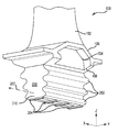
- FIG. 4A illustrates a perspective view of a fir tree type coupling, in accordance with various embodiments
- FIG. 4B illustrates a perspective view of the base of a fir tree coupling, in accordance with various embodiments.
- FIG. 5A illustrates the base of a fir tree coupling, in accordance with various embodiments
- FIG. 5B illustrates a section through the blade-disk attachment region between the rails of a fir tree coupling, in accordance with various embodiments
- FIG. 5C illustrates the base of a fir tree coupling, in accordance with various embodiments
- FIGS. 6A thru 6 E illustrate the profiles of rails at the base of a fir tree coupling, in accordance with various embodiments.
- FIG. 7 illustrates a method of manufacturing a fir tree coupling, in accordance with various embodiments.
- any reference to attached, fixed, connected or the like may include permanent, removable, temporary, partial, full and/or any other possible attachment option. Additionally, any reference to without contact (or similar phrases) may also include reduced contact or minimal contact. Surface shading lines may be used throughout the figures to denote different parts but not necessarily to denote the same or different materials. In some cases, reference coordinates may be specific to each figure.
- references to “a,” “an,” and/or “the” may include one or more than one and that reference to an item in the singular may also include the item in the plural.
- Gas turbine engine 2 is a two-spool turbofan that generally incorporates a fan section 4 , a compressor section 6 , a combustor section 8 and a turbine section 10 .
- Vanes 51 may be disposed throughout the gas turbine engine 2 .
- Alternative engines include, for example, an augmentor section among other systems or features.
- fan section 4 drives air along a bypass flow-path B while compressor section 6 drives air along a core flow-path C for compression and communication into combustor section 8 then expansion through turbine section 10 .
- a gas turbine engine may comprise an industrial gas turbine (IGT) or a geared aircraft engine, such as a geared turbofan, or non-geared aircraft engine, such as a turbofan, or may comprise any gas turbine engine as desired.
- IGT industrial gas turbine
- a geared aircraft engine such as a geared turbofan
- non-geared aircraft engine such as a turbofan
- Gas turbine engine 2 generally comprises a low speed spool 12 and a high speed spool 14 mounted for rotation about an engine central longitudinal axis X-X′ relative to an engine static structure 16 via several bearing systems 18 - 1 , 18 - 2 , and 18 - 3 .
- bearing systems is alternatively or additionally provided at locations, including for example, bearing system 18 - 1 , bearing system 18 - 2 , and bearing system 18 - 3 .
- Low speed spool 12 generally comprises an inner shaft 20 that interconnects a fan 22 , a low pressure compressor section 24 , e.g., a first compressor section, and a low pressure turbine section 26 , e.g., a second turbine section.
- Inner shaft 20 is connected to fan 22 through a geared architecture 28 that drives the fan 22 at a lower speed than low speed spool 12 .
- Geared architecture 28 comprises a gear assembly 42 enclosed within a gear housing 44 .
- Gear assembly 42 couples the inner shaft 20 to a rotating fan structure.
- High speed spool 14 comprises an outer shaft 80 that interconnects a high pressure compressor section 32 , e.g., second compressor section, and high pressure turbine section 34 , e.g., first turbine section.
- a combustor 36 is located between high pressure compressor section 32 and high pressure turbine section 34 .
- a mid-turbine frame 38 of engine static structure 16 is located generally between high pressure turbine section 34 and low pressure turbine section 26 .
- Mid-turbine frame 38 supports one or more bearing systems 18 , such as 18 - 3 , in turbine section 10 .
- Inner shaft 20 and outer shaft 80 are concentric and rotate via bearing systems 18 about the engine central longitudinal axis X-X′, which is collinear with their longitudinal axes.
- a “high pressure” compressor or turbine experiences a higher pressure than a corresponding “low pressure” compressor or turbine.
- the core airflow C is compressed by low pressure compressor section 24 then high pressure compressor section 32 , mixed and burned with fuel in combustor 36 , then expanded over high pressure turbine section 34 and low pressure turbine section 26 .
- Mid-turbine frame 38 includes surface structures 40 , which are in the core airflow path. Turbines 26 , 34 rotationally drive the respective low speed spool 12 and high speed spool 14 in response to the expansion.
- Gas turbine engine 2 is, for example, a high-bypass geared aircraft engine.
- the bypass ratio of gas turbine engine 2 is optionally greater than about six (6).
- the bypass ratio of gas turbine engine 2 is optionally greater than ten (10).
- Geared architecture 28 is an epicyclic gear train, such as a star gear system, e.g., sun gear in meshing engagement with a plurality of star gears supported by a carrier and in meshing engagement with a ring gear, or other gear system.
- Geared architecture 28 has a gear reduction ratio of greater than about 2.3 and low pressure turbine section 26 has a pressure ratio that is greater than about five (5).
- the bypass ratio of gas turbine engine 2 is greater than about ten (10:1).
- the diameter of fan 22 is significantly larger than that of the low pressure compressor section 24 , and the low pressure turbine section 26 has a pressure ratio that is greater than about 5:1.
- Low pressure turbine section 26 pressure ratio is measured prior to inlet of low pressure turbine section 26 as related to the pressure at the outlet of low pressure turbine section 26 prior to an exhaust nozzle. It should be understood, however, that the above parameters are exemplary of a suitable geared architecture engine and that the present disclosure contemplates other turbine engines including direct drive turbofans.
- a fir tree coupling for interfacing an airfoil (e.g., a blade) with a turbine disk of a gas turbine engine.
- a fir tree coupling may comprise a load beam having a longitudinal axis, a base, a first side, and a second side.
- the fir tree coupling may comprise a plurality of teeth running parallel or substantially parallel the load beam longitudinal axis and disposed on the first side and the second side of the load beam.
- the teeth have bearing surfaces which transmit loads at the blade-disk interface.
- the blade-disk interface load may be concentrated as a high stress in an attachment fillet disposed between the teeth of the fir tree coupling.
- the base of the fir tree coupling may comprise rails extending from the base between the first side and the second side which may reduce attachment fillet stress and tend to mitigate LCF.
- a blade assembly may comprise a fir tree coupling, an airfoil, and a platform having a dorsal and a ventral surface.
- the airfoil extends from the dorsal surface of the platform and the fir tree coupling extends from the ventral surface of the platform.
- the blade assembly is coupled to a turbine disk by the fir tree coupling which transmits the centrifugal force acting on the airfoil resulting from the airfoil's rotation about the gas turbine engine shaft to the turbine disk through the bearing surfaces of the fir tree coupling teeth.
- the centrifugal force induces bending in the teeth which tends to concentrate stresses at the lower most attachment fillet between the teeth.
- a blade assembly 100 comprises an airfoil 102 , a platform 104 , and a fir tree coupling 200 .
- Airfoil 102 extends from dorsal surface 106 of platform 104 .
- Fir tree coupling 200 includes teeth 202 and base 210 and extends from ventral surface 108 of platform 104 .
- Xyz axes are shown for convenience, with z extending perpendicular to the xy plane. In that regard, a measurement point displaced in the positive z-axis direction from a given reference point may be considered “above” or on “top” of the given reference point.
- Blade assembly 100 is inserted into turbine disk 301 and coupled by fir tree coupling 200 .
- centrifugal force 300 is generated, which is transmitted into disk 301 at bearing surfaces 203 of teeth 202 , tending to induce bending 302 , which tends to concentrate stress at attachment fillets 304 .
- the compressive force 303 is resisted by rails 204 and tends to reduce stress at attachment fillets 304 .
- cooling passages 216 in the base of a fir tree coupling may be disposed between rails such as rails 204 and extend upward (along the z-axis) from the base through the load beam to a top surface such as top surface 208 of a fir tree coupling. Cooling passages 216 may extend radially outward through the airfoil.
- Cooling passages 216 may have an opening in a base such as base 210 and may form part of a cooling system for a blade assembly such as blade assembly 100 and be in fluid communication with a second cooling passage disposed within a platform such as platform 104 or an airfoil such as airfoil 102 .
- rails such as rails 204 may comprise at least one of a tapered sidewall 600 wherein the tapered sidewall extends below the base at an angle, a convex sidewall 602 wherein the rail extension below the base is bounded by a convex curvature of the convex sidewall, a vertical sidewall 604 wherein the rail sidewall extends perpendicular below the base, a sidewall comprising a sidewall step 608 wherein the sidewall has a step 609 cut into a portion of the rail thickness, or a concave sidewall 610 wherein the rail sidewall extension below the base is bounded by a concave curvature of the sidewall.
- a method 700 of manufacturing a fir tree coupling may comprise forming a load beam 702 having a longitudinal axis, a base, a first side, a second side, a tooth running parallel to the longitudinal axis and disposed on the first side of the load beam, and forming a rail 704 extending across the base of the load beam between the first side and the second side.
- Forming may comprise subtractive manufacturing such as casting, forging, milling, grinding, machining, and the like.
- Forming may also comprise additive manufacturing, such as electron-beam melting, selective laser sintering, electron-beam freeform fabrication, and the like.
- Forming may also comprises joining such as welding, brazing and/or other suitable methods.
Landscapes
- Engineering & Computer Science (AREA)
- Mechanical Engineering (AREA)
- General Engineering & Computer Science (AREA)
- Architecture (AREA)
- Turbine Rotor Nozzle Sealing (AREA)
Abstract
Description
Claims (18)
Priority Applications (2)
| Application Number | Priority Date | Filing Date | Title |
|---|---|---|---|
| US15/009,328 US10077665B2 (en) | 2016-01-28 | 2016-01-28 | Turbine blade attachment rails for attachment fillet stress reduction |
| EP17153625.3A EP3199765B1 (en) | 2016-01-28 | 2017-01-27 | Turbine blade attachment rails for attachment fillet stress reduction |
Applications Claiming Priority (1)
| Application Number | Priority Date | Filing Date | Title |
|---|---|---|---|
| US15/009,328 US10077665B2 (en) | 2016-01-28 | 2016-01-28 | Turbine blade attachment rails for attachment fillet stress reduction |
Publications (2)
| Publication Number | Publication Date |
|---|---|
| US20170218775A1 US20170218775A1 (en) | 2017-08-03 |
| US10077665B2 true US10077665B2 (en) | 2018-09-18 |
Family
ID=57909559
Family Applications (1)
| Application Number | Title | Priority Date | Filing Date |
|---|---|---|---|
| US15/009,328 Active 2036-12-10 US10077665B2 (en) | 2016-01-28 | 2016-01-28 | Turbine blade attachment rails for attachment fillet stress reduction |
Country Status (2)
| Country | Link |
|---|---|
| US (1) | US10077665B2 (en) |
| EP (1) | EP3199765B1 (en) |
Families Citing this family (2)
| Publication number | Priority date | Publication date | Assignee | Title |
|---|---|---|---|---|
| GB201811205D0 (en) * | 2018-07-09 | 2018-08-29 | Rolls Royce Plc | Blade for a gas turbine engine |
| FR3087479B1 (en) * | 2018-10-23 | 2022-05-13 | Safran Aircraft Engines | DAWN OF TURBOMACHINE |
Citations (12)
| Publication number | Priority date | Publication date | Assignee | Title |
|---|---|---|---|---|
| US20050224144A1 (en) * | 2004-01-16 | 2005-10-13 | Tresa Pollock | Monocrystalline alloys with controlled partitioning |
| US7690896B2 (en) * | 2005-05-27 | 2010-04-06 | United Technologies Corporation | Gas turbine disk slots and gas turbine engine using same |
| US7708525B2 (en) * | 2005-02-17 | 2010-05-04 | United Technologies Corporation | Industrial gas turbine blade assembly |
| US7758309B2 (en) * | 2004-07-09 | 2010-07-20 | Siemens Aktiengesellschaft | Vane wheel of turbine comprising a vane and at least one cooling channel |
| US8277186B2 (en) * | 2008-05-26 | 2012-10-02 | Kabushiki Kaisha Toshiba | Turbine blade assembly and steam turbine |
| US8573942B2 (en) * | 2008-11-25 | 2013-11-05 | Alstom Technology Ltd. | Axial retention of a platform seal |
| US20150037161A1 (en) * | 2013-07-30 | 2015-02-05 | MTU Aero Engines AG | Method for mounting a gas turbine blade in an associated receiving recess of a rotor base body |
| US9328622B2 (en) * | 2012-06-12 | 2016-05-03 | General Electric Company | Blade attachment assembly |
| US20160146016A1 (en) * | 2014-11-24 | 2016-05-26 | General Electric Company | Rotor rim impingement cooling |
| US20160265378A1 (en) * | 2013-11-18 | 2016-09-15 | Siemens Aktiengesellschaft | Sealing system and gas turbine |
| US20170067356A1 (en) * | 2015-09-04 | 2017-03-09 | Gregory Vogel | Flow control device for rotating flow supply system |
| FR3043133A1 (en) * | 2015-10-30 | 2017-05-05 | Turbomeca | TURBOMACHINE DAWN COMPRISING A FOOT STAGE AND CROSSED BY COOLING AIR CAVITIES |
Family Cites Families (2)
| Publication number | Priority date | Publication date | Assignee | Title |
|---|---|---|---|---|
| BE530136A (en) * | 1953-07-06 | |||
| FR2275975A5 (en) * | 1973-03-20 | 1976-01-16 | Snecma | Gas turbine blade with cooling passages - holes parallel to blade axis provide surface layer of cool air |
-
2016
- 2016-01-28 US US15/009,328 patent/US10077665B2/en active Active
-
2017
- 2017-01-27 EP EP17153625.3A patent/EP3199765B1/en active Active
Patent Citations (12)
| Publication number | Priority date | Publication date | Assignee | Title |
|---|---|---|---|---|
| US20050224144A1 (en) * | 2004-01-16 | 2005-10-13 | Tresa Pollock | Monocrystalline alloys with controlled partitioning |
| US7758309B2 (en) * | 2004-07-09 | 2010-07-20 | Siemens Aktiengesellschaft | Vane wheel of turbine comprising a vane and at least one cooling channel |
| US7708525B2 (en) * | 2005-02-17 | 2010-05-04 | United Technologies Corporation | Industrial gas turbine blade assembly |
| US7690896B2 (en) * | 2005-05-27 | 2010-04-06 | United Technologies Corporation | Gas turbine disk slots and gas turbine engine using same |
| US8277186B2 (en) * | 2008-05-26 | 2012-10-02 | Kabushiki Kaisha Toshiba | Turbine blade assembly and steam turbine |
| US8573942B2 (en) * | 2008-11-25 | 2013-11-05 | Alstom Technology Ltd. | Axial retention of a platform seal |
| US9328622B2 (en) * | 2012-06-12 | 2016-05-03 | General Electric Company | Blade attachment assembly |
| US20150037161A1 (en) * | 2013-07-30 | 2015-02-05 | MTU Aero Engines AG | Method for mounting a gas turbine blade in an associated receiving recess of a rotor base body |
| US20160265378A1 (en) * | 2013-11-18 | 2016-09-15 | Siemens Aktiengesellschaft | Sealing system and gas turbine |
| US20160146016A1 (en) * | 2014-11-24 | 2016-05-26 | General Electric Company | Rotor rim impingement cooling |
| US20170067356A1 (en) * | 2015-09-04 | 2017-03-09 | Gregory Vogel | Flow control device for rotating flow supply system |
| FR3043133A1 (en) * | 2015-10-30 | 2017-05-05 | Turbomeca | TURBOMACHINE DAWN COMPRISING A FOOT STAGE AND CROSSED BY COOLING AIR CAVITIES |
Non-Patent Citations (2)
| Title |
|---|
| FR 3043133-Translation with Original from Espacenet. * |
| FR 3043133—Translation with Original from Espacenet. * |
Also Published As
| Publication number | Publication date |
|---|---|
| EP3199765B1 (en) | 2020-09-30 |
| US20170218775A1 (en) | 2017-08-03 |
| EP3199765A1 (en) | 2017-08-02 |
Similar Documents
| Publication | Publication Date | Title |
|---|---|---|
| US10047611B2 (en) | Turbine blade attachment curved rib stiffeners | |
| US10808543B2 (en) | Rotors with modulus mistuned airfoils | |
| US9011085B2 (en) | Ceramic matrix composite continuous “I”-shaped fiber geometry airfoil for a gas turbine engine | |
| US10036259B2 (en) | Turbine blade having film cooling hole arrangement | |
| US20140000285A1 (en) | Gas turbine engine turbine vane platform core | |
| US20140000287A1 (en) | Gas turbine engine turbine vane airfoil profile | |
| WO2014014750A1 (en) | Joint between airfoil and shroud | |
| US10060268B2 (en) | Turbine blade having film cooling hole arrangement | |
| US20160010463A1 (en) | Gas turbine engine high lift airfoil cooling in stagnation zone | |
| EP3453483A1 (en) | Method of making integrally bladed rotor | |
| US10119400B2 (en) | High pressure rotor disk | |
| EP3078807B2 (en) | Cooling passages for a gas turbine engine component | |
| EP3103965A1 (en) | Attachment arrangement for turbine engine component | |
| US20150308449A1 (en) | Gas turbine engine component with brazed cover | |
| US10077665B2 (en) | Turbine blade attachment rails for attachment fillet stress reduction | |
| US20150300258A1 (en) | Cooling hole arrangement for engine component | |
| EP3299587B1 (en) | Gas turbine engine airfoil | |
| EP3098387B1 (en) | Installation fault tolerant damper | |
| WO2014007934A1 (en) | Gas turbine engine turbine vane airfoil profile | |
| EP3550105B1 (en) | Gas turbine engine rotor disk | |
| US11098591B1 (en) | Turbine blade with contoured fillet | |
| US11634990B2 (en) | Component with mechanical locking features incorporating adaptive cooling and method of making | |
| US20190039167A1 (en) | Method of making integrally bladed rotor |
Legal Events
| Date | Code | Title | Description |
|---|---|---|---|
| AS | Assignment |
Owner name: UNITED TECHNOLOGIES CORPORATION, CONNECTICUT Free format text: ASSIGNMENT OF ASSIGNORS INTEREST;ASSIGNORS:THISTLE, CHARLES;HASSAN, MOHAMED;REEL/FRAME:037612/0815 Effective date: 20160128 |
|
| STCF | Information on status: patent grant |
Free format text: PATENTED CASE |
|
| AS | Assignment |
Owner name: RAYTHEON TECHNOLOGIES CORPORATION, MASSACHUSETTS Free format text: CHANGE OF NAME;ASSIGNOR:UNITED TECHNOLOGIES CORPORATION;REEL/FRAME:054062/0001 Effective date: 20200403 |
|
| AS | Assignment |
Owner name: RAYTHEON TECHNOLOGIES CORPORATION, CONNECTICUT Free format text: CORRECTIVE ASSIGNMENT TO CORRECT THE AND REMOVE PATENT APPLICATION NUMBER 11886281 AND ADD PATENT APPLICATION NUMBER 14846874. TO CORRECT THE RECEIVING PARTY ADDRESS PREVIOUSLY RECORDED AT REEL: 054062 FRAME: 0001. ASSIGNOR(S) HEREBY CONFIRMS THE CHANGE OF ADDRESS;ASSIGNOR:UNITED TECHNOLOGIES CORPORATION;REEL/FRAME:055659/0001 Effective date: 20200403 |
|
| MAFP | Maintenance fee payment |
Free format text: PAYMENT OF MAINTENANCE FEE, 4TH YEAR, LARGE ENTITY (ORIGINAL EVENT CODE: M1551); ENTITY STATUS OF PATENT OWNER: LARGE ENTITY Year of fee payment: 4 |
|
| AS | Assignment |
Owner name: RTX CORPORATION, CONNECTICUT Free format text: CHANGE OF NAME;ASSIGNOR:RAYTHEON TECHNOLOGIES CORPORATION;REEL/FRAME:064714/0001 Effective date: 20230714 |