US10075357B2 - Transport of time sensitive information using the internet - Google Patents
Transport of time sensitive information using the internet Download PDFInfo
- Publication number
- US10075357B2 US10075357B2 US15/288,099 US201615288099A US10075357B2 US 10075357 B2 US10075357 B2 US 10075357B2 US 201615288099 A US201615288099 A US 201615288099A US 10075357 B2 US10075357 B2 US 10075357B2
- Authority
- US
- United States
- Prior art keywords
- node
- overlay
- packet
- network
- time
- Prior art date
- Legal status (The legal status is an assumption and is not a legal conclusion. Google has not performed a legal analysis and makes no representation as to the accuracy of the status listed.)
- Active, expires
Links
Images


Classifications
-
- H—ELECTRICITY
- H04—ELECTRIC COMMUNICATION TECHNIQUE
- H04L—TRANSMISSION OF DIGITAL INFORMATION, e.g. TELEGRAPHIC COMMUNICATION
- H04L43/00—Arrangements for monitoring or testing data switching networks
- H04L43/08—Monitoring or testing based on specific metrics, e.g. QoS, energy consumption or environmental parameters
- H04L43/0852—Delays
-
- H—ELECTRICITY
- H04—ELECTRIC COMMUNICATION TECHNIQUE
- H04L—TRANSMISSION OF DIGITAL INFORMATION, e.g. TELEGRAPHIC COMMUNICATION
- H04L1/00—Arrangements for detecting or preventing errors in the information received
- H04L1/08—Arrangements for detecting or preventing errors in the information received by repeating transmission, e.g. Verdan system
-
- H—ELECTRICITY
- H04—ELECTRIC COMMUNICATION TECHNIQUE
- H04L—TRANSMISSION OF DIGITAL INFORMATION, e.g. TELEGRAPHIC COMMUNICATION
- H04L1/00—Arrangements for detecting or preventing errors in the information received
- H04L1/12—Arrangements for detecting or preventing errors in the information received by using return channel
- H04L1/16—Arrangements for detecting or preventing errors in the information received by using return channel in which the return channel carries supervisory signals, e.g. repetition request signals
- H04L1/18—Automatic repetition systems, e.g. Van Duuren systems
- H04L1/1829—Arrangements specially adapted for the receiver end
- H04L1/1835—Buffer management
-
- H—ELECTRICITY
- H04—ELECTRIC COMMUNICATION TECHNIQUE
- H04L—TRANSMISSION OF DIGITAL INFORMATION, e.g. TELEGRAPHIC COMMUNICATION
- H04L43/00—Arrangements for monitoring or testing data switching networks
- H04L43/12—Network monitoring probes
-
- H—ELECTRICITY
- H04—ELECTRIC COMMUNICATION TECHNIQUE
- H04L—TRANSMISSION OF DIGITAL INFORMATION, e.g. TELEGRAPHIC COMMUNICATION
- H04L45/00—Routing or path finding of packets in data switching networks
- H04L45/64—Routing or path finding of packets in data switching networks using an overlay routing layer
-
- H—ELECTRICITY
- H04—ELECTRIC COMMUNICATION TECHNIQUE
- H04L—TRANSMISSION OF DIGITAL INFORMATION, e.g. TELEGRAPHIC COMMUNICATION
- H04L47/00—Traffic control in data switching networks
- H04L47/10—Flow control; Congestion control
- H04L47/28—Flow control; Congestion control in relation to timing considerations
- H04L47/283—Flow control; Congestion control in relation to timing considerations in response to processing delays, e.g. caused by jitter or round trip time [RTT]
-
- H—ELECTRICITY
- H04—ELECTRIC COMMUNICATION TECHNIQUE
- H04L—TRANSMISSION OF DIGITAL INFORMATION, e.g. TELEGRAPHIC COMMUNICATION
- H04L47/00—Traffic control in data switching networks
- H04L47/10—Flow control; Congestion control
- H04L47/30—Flow control; Congestion control in combination with information about buffer occupancy at either end or at transit nodes
Definitions
- some applications introduce a large amount of buffering at the destination.
- the destination may buffer many seconds of the video before beginning the presentation of this video stream.
- By introducing a large buffer it may be possible to accommodate more jitter and more errors in the transmission.
- a system and method that uses the internet to deliver time sensitive information includes an overlay network, having a plurality of overlay nodes, which are used to deliver the time sensitive information.
- the sending node periodically requests each overlay node in the path between the sending node and the receiving node to force a retransmission of a packet, while also forwarding that same packet to the next overlay node.
- the delay associated with each link in the path can be quantified and recorded by the receiving node.
- the receiving node may determine an optimal buffer time. This buffer time is the amount of buffering performed at the receiving node prior to outputting the time sensitive information.
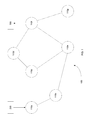
- FIG. 1 is an illustration of the system according to one embodiment
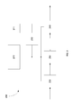
- FIG. 2 is a block diagram of the sending node
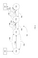
- FIG. 3 is an illustration showing the retransmissions that are performed
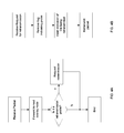
- FIGS. 4A and 4B are flowcharts of processes performed by the overlay nodes
- FIG. 5 shows the flow of information in the receiving node
- FIG. 6 is a block diagram of the receiving node.
- time sensitive information When time sensitive information is delivered, it is often buffered at the receiving node, so that its presentation to the user is smooth and jitter free. For example, when a video stream is delivered, several seconds (or more) of that video are buffered by the receiving node before any of the video is presented. This buffer time is used to account for inconsistency in transmission time between the sending node and the receiving node, and also to account for possible retransmission.
- Determining an appropriate buffer time is difficult. If the buffer time is too short, the user may still see the effects of inconsistent transmission delays and retransmissions. If the buffer time is too long, the user may be dissatisfied in the delay between pressing “PLAY” and the actual commencement of the video. Further, as noted above, in applications where time sensitive information is sent in both directions, such as Skype or Facetime, the delay may have a serious impact on the user experience.
- the present system characterizes and quantifies major sources of jitter and variability, and uses these quantified values to determine an optimal buffer time.
- FIG. 1 shows a typical system 100 that may be used according to one embodiment.
- the system includes a sending node 200 , and a receiving node 300 . These nodes communicate through an overlay network, comprised of a plurality of overlay nodes 110 a - g .
- the overlay network operates on top of the internet.
- the TCP protocol is used to create a connection between a source and a destination, where these two nodes are the only nodes that track sequence numbers and packet loss.
- packets 1 - 5 are to be delivered from a source node to a destination node over the internet using TCP, only the destination node checks these sequence numbers to determine if all packets arrived successfully. If a packet was lost, only the destination node and the original source are able to identify the need for retransmission. In other words, the intermediate nodes do not track whether all packets and sequence numbers are transmitted to the destination.
- sequence numbers are tracked privately between each pair of adjacent overlay node 110 a - g .
- a set of packets is sent from the sending node 200 to the receiving node 300 . These packets may pass through overlay nodes 110 a , 110 c , 110 e and 110 f . If overlay node 110 e determines that a packet was lost, it will request retransmission of that packet from the previous overlay node 110 c . In this way, the effects of a lost packet, and specifically, the delay attributable to retransmitting the packet, are made smaller, as the loss is identified sooner and the retransmission travels a smaller distance.
- packets are delivered through the overlay network using UDP (user datagram protocol) to communicate between overlay nodes 110 a - g.
- UDP user datagram protocol
- a H.264 video/AAC audio source 220 may be disposed proximate or within the sending node 200 .
- This H.264 video/AAC audio source 220 may output a constant bit rate (CBR) transport stream for transmission to a destination.
- CBR transport stream is delivered to a packetizing block 230 .
- the packetizing block 230 converts the CBR transport stream into a series of discrete packets.
- the packetizing block 230 may also add erasure correction codes.
- forward erasure correction (FEC) is used, whereby additional redundant packets are added to the original packets. For example, for every 10 original packets, 3 - 7 redundant packets may be created and transmitted with the original packets.
- FEC forward erasure correction
- the redundant packets allow for the reconstruction of the original packets in the event that one or more of the original packets are lost during transmission.
- the packetizing block 230 may be special purpose hardware designed to perform these functions.
- the packetizing block 230 may be a software application executed by the processing unit 210 .
- the packets created by the packetizing block 230 are then forwarded to the network interface 240 , which transmits these packets over the internet, using the overlay network.
- the network interface 240 may be a hardware component, such as a NIC (network interface card), or may include a hardware component in conjunction with software executed by the processing unit 210 .
- the sending node 200 also includes a forced retry block 250 , in communication with the network interface 240 .
- the forced retry block 250 is used to flag certain packets for forced retransmission, as will be described in more detail below.
- the sending node 200 may comprise a processing unit 210 .
- the processing unit 210 may be any suitable device, such as a PC, server, special purpose controller or the like. In certain embodiments, multiple processing units may be used.
- the processing unit 210 is in communication with a memory 211 , which contains the instructions, which when executed by the processing unit 210 , perform the functions described herein.
- the processing unit 210 is in communication with the H.264 video/AAC audio source 220 , the packetizing block 230 , the network interface 240 and the forced retry block 250 . In other embodiments, the processing unit 210 may not be in communication with one or more of these components.
- FIG. 2 shows a H.264 video/AAC audio source 220
- other sources of time sensitive information may also be employed and the disclosure is not limited to this embodiment.
- FIG. 6 shows a receiving node 300 .
- the receiving node 300 comprises a processing unit 310 .
- the processing unit 310 may be any suitable device, such as a PC, server, special purpose controller or the like. In certain embodiments, multiple processing units may be used.
- the processing unit 310 is in communication with a memory 311 , which contains the instructions, which when executed by the processing unit 310 , perform the functions described herein.
- the receiving node 300 also comprises a network interface 320 , which through the incoming packets arrive.
- the network interface 320 may be a hardware component, such as a NIC (network interface card), or may include a hardware component in conjunction with software executed by the processing unit 310 .
- the receiving node 300 comprises a calculation block 330 .
- the calculation block 330 may include a clock function, such that the arrival time of all incoming packets can be determined.
- the calculation block 330 may also include the logic necessary to decode portions of the incoming packets so as to determine and store the delay associated with each link on the overlay network, as described in more detail below.
- the calculation block 330 may be a software application executed by the processing unit 310 . In other embodiments, it may be a specialized hardware component.
- the receiving node 300 also comprises a packet scheduler 340 that is responsible for arranging the incoming packets in the proper sequence prior to presentation.
- the packet scheduler 340 may include a memory element, which is used to store the properly arranged packets prior to presentation.
- the receiving node 300 may also comprise a presentation block, in communication with the packet scheduler 340 , to display the time sensitive information.
- a video decoder may be used as part of the presentation block. As packets are transmitted from the packet scheduler 340 , they may be decoded and displayed using the presentation block.
- the calculated optimal buffer time is used by the packet scheduler 340 to determine how many packets to store before transmitting to the presentation block.
- a larger buffer time implies that more packets will be stored within the packet scheduler 340 .
- Each of the network interface 320 , the calculation block 330 and the packet scheduler 340 may be in communication with the processing unit 310 . In other embodiments, one or more of these components may not be in communication with the processing unit.
- the operation of the receiving node 300 is described in more detail below and in conjunction with FIG. 5 .
- the sending node 200 transmits UDP packets over the overlay network.
- packet loss, jitter and delay are all unpredictable in the overlay network.
- the goals of the system 100 are to deliver the time sensitive information in as little time as possible (i.e. lowest latency) while protecting it from packet loss and temporal distortion (i.e. delay variability or jitter).
- the receiving node 300 receives the packets transmitted by the sending node 200 . Delivery time uncertainty and packet loss complicate the function of the receiving node 300 . Specifically, when retransmissions occur, packets may arrive later than expected and may also arrive out of order. For example, the sending node may transmit packets 1 - 5 . However, due to retransmissions and other communications issues, the packets may arrive at the receiving node 300 in a different order, such as 1, 2, 4, 5, 3. It is one of the functions of the receiving node 300 to reorder these packets. Additionally, since packet 3 must be displayed after packet 2 , the receiving node 300 must also provide sufficient buffering to allow packet 3 to arrive before presenting this data to the user. In other words, the receiving node 300 must store a certain amount of information internally, such as within the packet scheduler 340 , before outputting this information.
- certain packets are specially marked as retransmission probes.
- the forced retry block 250 modifies the header of a particular packet to mark it for special processing.
- the frequency at which these retransmission probes are generated is variable, and is not limited by this disclosure. However, in certain embodiments, retransmission probes may be generated every 250 ms.
- These retransmission probes may be regular packets that are specially marked. When a retransmission probe reaches an overlay node, that particular overlay node forwards the specially marked packet to the next overlay node, but also requests a retransmission of that packet from the overlay node from which it was sent.
- FIG. 3 The flow of packets is best seen in FIG. 3 .
- the path between sending node 200 and receiving node 300 is through overlay nodes 110 a , 110 c , 110 e and 110 f .
- Normal packets traverse this overlay network using links 120 a , 120 b and 120 c , where a link is used to connect two adjacent overlay nodes.
- retransmission probes are treated differently.
- Overlay node 110 a sends a retransmission probe to overlay node 110 c over link 120 a , as is typically done.
- Overlay node 110 c seeing that the received packet is a retransmission probe, sends a request for retransmission 130 a back to overlay node 110 a .
- This process, executed by each overlay node, is shown in FIG. 4A .
- the overlay node 110 a sends a retransmission 140 a to overlay node 110 c .
- the overlay node 110 a may also indicate an indication in the retransmission 140 a of the link over which the retransmission was sent. This process, which is executed by each overlay node, is shown in FIG. 4B .
- overlay node 110 c receives two packets from overlay node 110 a; a retransmission probe and a retransmission 140 a indicating that the retransmission was over link 120 a . Overlay node 110 c forwards both of these packets to overlay node 110 e over link 120 b.
- overlay node 110 e When overlay node 110 e receives the retransmission probe, it sends a request for retransmission 130 b back to overlay node 110 c . Overlay node 110 e also forwards the retransmission probe to overlay node 110 f.
- overlay node 110 e also forwards the retransmission 140 a to overlay node 110 f.
- overlay node 110 c After receiving the request for retransmission 130 b , overlay node 110 c sends a retransmission 140 b to overlay node 110 e . Note that the special marking that indicated that this is a retransmission probe is removed before the retransmission 140 b is sent.
- the overlay node 110 c may also include in the retransmission 140 b an indication of the link over which the retransmission was sent.
- overlay node 110 e receives three packets: the retransmission probe over link 120 b; a first retransmission 140 a indicating that the retransmission was over link 120 a , and a second retransmission 140 b indicating that the retransmission was over link 120 b .
- the overlay node 110 e forwards all three of these packets to the overlay node 110 f.
- Overlay node 110 f repeats this process by forwarding the retransmission probe, sending a request for retransmission 130 c and forwarding retransmissions 140 a , 140 b and 140 c.
- a retransmission probe when complete, will generate N+1 packets, where N is the number of links traversed by the packet. All of these packets are delivered to the receiving node 300 .
- the receiving node 300 is then able to estimate the delay caused by retransmissions on each of the links in the overlay network. Basically, the receiving node 300 will receive the retransmission probe first. The receiving node 300 notes the time of receipt of this retransmission probe. Note that this time need not be at all related to the time used by any other node in the overlay network. In certain embodiments, the receiving node 300 may compute the time through the network, which is representative of the time consumed by the packet as it traversed through the network, offset by the difference in the clocks (i.e. clock skew) at the sending node and the receiving node. This may be based on its receipt time, less the timestamp applied to the packet by the original sending node 200 . In other words, the receiving node 300 may compute:
- Time inNetwork T receiver ⁇ T sender , where T receiver is correlated to the clock at the receiving node 300 , and T sender is a timestamp in the packet.
- This calculated value also referred to as “time in network” is a measure of the time that the packet was actually traversing the network and also includes a offset to account for the difference in the receiver clock and the sender clock.
- the time in network of that packet is calculated.
- the time in network of all packets that are not retransmissions are used to compute a smoothed time in network.
- each of the retransmissions 140 a - 140 c arrives at the receiving node 300 , the receiving node 300 notes the time of receipt of each of these retransmissions. Again the time in network for each retransmission 140 a - 140 c may also be computed. Finally, by subtracting the smoothed time in network from the time in network for each retransmission, the delay associated with each link may be calculated. Importantly, because each link delay is calculated as a difference, the offset between the sending node clock and the receiving node clock is eliminated.
- FIG. 5 pictorially shows this process.
- the receiving node 300 checks to see if it was a retransmitted packet. If it was not retransmitted, the receiving node 300 calculates the time in network, such as by using the equation shown above, and updates the smoothed time in network. In other embodiments, only the arrival time, as recorded by the receiving node 300 , is saved. The packet is then forwarded to the packet scheduler 340 to be inserted in the output queue. Thus, calculations of the time in network value are performed for all packets that are not retransmissions. These time in network values may be used to create a smoothed time in network.
- This smoothed time in network represents the time difference between the time the packet was transmitted by the sending node 200 (based on the sending node's clock) and the time that the packet arrived at the receiving node 300 (based on the receiving node's clock). As such, this smoothed time in network also serves to correlate the clock at the sending node 200 to the clock at the receiving node 300 .
- the smoothed time in network is an averaged value based on the time in network values of all packets that were not retransmissions.
- a subset of the packets is used to compute the smoothed time in network value.
- the smoothed time in network value may be the average of only the retransmission probes, and may not include all other packets.
- the receiving node 300 calculates the time in network for all incoming packets, not just the retransmission probes. This technique may provide a more accurate smoothed time in network value.
- the receiving node 300 again calculates the time in network (as shown above). The receiving node 300 then compares this time with the updated smoothed time in network value. This difference is the delay caused by the retransmission. Further, in certain embodiments, the retransmissions indicate which link was retried, allowing the receiving node to calculate the delay for each particular link in the overlay network. This allows the receiving node to create a database, as shown in FIG. 5 , which stores the delay associated with each link in the overlay network. This database may be stored within the calculation block 330 (see FIG. 6 ). The retransmissions 140 a - c may then be forwarded to the packet scheduler 340 . In the case of intentional retransmissions, as described above, the packet scheduler 340 may simply discard these retransmissions. In certain embodiments, the intentional retransmissions are discarded before being forwarded to the packet scheduler 340 .
- the receiving node 300 may use averaged or smoothed values, as well as other derived statistics, such as delay variance or maximum delay, to calculate the delay times stored in the database. For example, as explained above, transmission time through the internet may be variable. Therefore, a smoothing function may provide a more accurate representation of the delay associated with each link.
- the receiving node 300 is able to observe the retransmission delay associated with each link in the overlay network. The receiving node 300 can then use this information to determine the optimal buffer time to use.
- the receiving node 300 may use the largest single link delay to calculate the optimal buffer time. In other embodiments, the receiving node 300 may use the sum of the two largest link delays to calculate the buffer time. Of course, the receiving node 300 may perform other functions based on these delay times to calculate the optimal buffer time.
- the receiving node 300 may determine several parameters that are useful for the packet scheduler 340 .
- the smoothed time in network is an indication of the relative time difference between the sending node 200 and the receiving node 300 . This value includes average transmission time and the skew between the sending node clock and the receiving node clock.
- the values stored in the database are representative of the delays through the overlay network. Based on these delay values, the receiving node 300 may determine a delay factor, which is a function of the link delays that are computed and stored in the database. By adding the smoothed time in network value to the delay factor, an optimal buffer time may be determined. In other embodiments, the delay factor may be used in conjunction with other parameters to determine the optimal buffer time.
- This optimal buffer time dictates the operation of the packet scheduler 340 .
- the packet scheduler 340 may transmit packets based on the sending node's timestamp. When the sending node's timestamp, plus the optimal buffer time, is equal to the present time (as determined by the sending node), the packet scheduler 340 transmits the packet.
- the delay may be characterized by performing the following steps:
- Portions of this process may be performed by each overlay node that is in the path of the retransmission probe. For example, the receive and forward steps described above may be performed by each overlay node. Thus, the receiving node would receive a number of packets equal to one more than the number of links traversed by the original specially marked packet.
- the sending node 200 executes a portion of this sequence. Specifically, the sending node 200 executes the following sequence:
- the receiving node 300 is an overlay node that also requests retransmissions.
- the receiving node 300 executes that following sequence:
- This process may be repeated for each overlay node that is in the path of the retransmission probe.
- the receiving node would receive a number of packets equal to one more than the number of links traversed by the original specially marked packet.
- Each overlay node 110 a - g comprises at least one network interface to allow it to receive and transmit packets over the overlay network. Additionally, each overlay node 110 a - g comprises a processing unit in communication with a suitable memory device.
- the memory device may include instructions, which when executed by the overlay node, allow it to performed the functions described herein and shown in FIGS. 4A-4B .
- the present disclosure discloses a method by which a receiving node can determine an optimized buffer time for the presentation of time sensitive information transmitted over an overlay network.
- the receiving node first calculates the delay associated with retries at each link in the overlay network. Then, using this delay information, the receiving node determines an optimized buffer time.
Landscapes
- Engineering & Computer Science (AREA)
- Computer Networks & Wireless Communication (AREA)
- Signal Processing (AREA)
- Environmental & Geological Engineering (AREA)
- Data Exchanges In Wide-Area Networks (AREA)
Abstract
Description
-
- transmit a specially marked packet from a sending node to a receiving node through the overlay network, where the overlay network comprises a plurality of overlay nodes connecting by a plurality of links, wherein the packet is marked as a retransmission probe;
- receive the specially marked packet at a second overlay node from a first overlay node in the overlay network;
- forward the specially marked packet from the second overlay node and request retransmission of the specially marked packet to the second overlay node from the first overlay node;
- receive the retransmitted packet from the first overlay node at the second overlay node;
- forward the retransmitted packet from the second overlay node;
- receive the specially marked packet and the retransmitted packet at the receiving node;
- determine, at the receiving node, a difference between a smoothed time in network and the time in network of the retransmitted packet; and
- calculate, at the receiving node, the delay associated with retransmission of packets between the first overlay node and the second overlay node.
-
- transmits a specially marked packet to a receiving node through the overlay network, where the overlay network comprises a plurality of overlay nodes connecting by a plurality of links, wherein the packet is marked as a retransmission probe;
- receives a request for retransmission from the next overlay node (if the sending node is an overlay node);
- modifies the retransmission to include an indication of the link and removes the special marking(if the sending node is an overlay node); and
- sends a retransmission to the overlay node that requested retransmission(if the sending node is an overlay node).
-
- receive the specially marked packet at a receiving node from a previous overlay node in the overlay network;
- request retransmission of the specially marked packet to the receiving node from the previous overlay node;
- receive the retransmitted packet from the previous overlay node at the receiving node;
- determine, at the receiving node, a difference between the smoothed time in network and the time in network of the retransmitted packet; and
- calculate, at the receiving node, the delay associated with retransmission of packets between each overlay node in the overlay network.
Claims (12)
Priority Applications (1)
| Application Number | Priority Date | Filing Date | Title |
|---|---|---|---|
| US15/288,099 US10075357B2 (en) | 2015-10-14 | 2016-10-07 | Transport of time sensitive information using the internet |
Applications Claiming Priority (2)
| Application Number | Priority Date | Filing Date | Title |
|---|---|---|---|
| US201562241407P | 2015-10-14 | 2015-10-14 | |
| US15/288,099 US10075357B2 (en) | 2015-10-14 | 2016-10-07 | Transport of time sensitive information using the internet |
Publications (2)
| Publication Number | Publication Date |
|---|---|
| US20170111252A1 US20170111252A1 (en) | 2017-04-20 |
| US10075357B2 true US10075357B2 (en) | 2018-09-11 |
Family
ID=58517822
Family Applications (1)
| Application Number | Title | Priority Date | Filing Date |
|---|---|---|---|
| US15/288,099 Active 2036-11-18 US10075357B2 (en) | 2015-10-14 | 2016-10-07 | Transport of time sensitive information using the internet |
Country Status (4)
| Country | Link |
|---|---|
| US (1) | US10075357B2 (en) |
| EP (1) | EP3363161B1 (en) |
| CA (1) | CA3001583C (en) |
| WO (1) | WO2017066089A1 (en) |
Families Citing this family (1)
| Publication number | Priority date | Publication date | Assignee | Title |
|---|---|---|---|---|
| CN111614574A (en) * | 2019-02-26 | 2020-09-01 | 华为技术有限公司 | A communication method, device and system |
Citations (6)
| Publication number | Priority date | Publication date | Assignee | Title |
|---|---|---|---|---|
| US20050083848A1 (en) * | 2003-10-20 | 2005-04-21 | Huai-Rong Shao | Selecting multiple paths in overlay networks for streaming data |
| US20080062879A1 (en) * | 2006-09-13 | 2008-03-13 | Asankya Networks, Inc. | Systems and Methods of Improving Performance of Transport Protocols in a Multi-Path Environment |
| US20100165830A1 (en) * | 2008-12-22 | 2010-07-01 | LiveTimeNet, Inc. | System and method for recovery of packets in overlay networks |
| US7940685B1 (en) * | 2005-11-16 | 2011-05-10 | At&T Intellectual Property Ii, Lp | Method and apparatus for monitoring a network |
| US20140295865A1 (en) * | 2011-12-09 | 2014-10-02 | Telefonaktiebolaget L M Ericsson (Publ) | Scheduling of delay-sensitive traffic |
| US20150109942A1 (en) | 2013-10-22 | 2015-04-23 | Cisco Technology, Inc. | Detecting packet loss and retransmission in a network environment |
Family Cites Families (3)
| Publication number | Priority date | Publication date | Assignee | Title |
|---|---|---|---|---|
| US7643503B2 (en) * | 2004-07-30 | 2010-01-05 | Sony Corporation | System and method for dynamically determining retransmit buffer time |
| WO2013025146A2 (en) | 2011-08-17 | 2013-02-21 | Telefonaktiebolaget L M Ericsson (Publ) | Method and controlling network node in a radio access network |
| US8923270B2 (en) * | 2011-10-04 | 2014-12-30 | The Chinese University Of Hong Kong | Method for link buffer size and queue length estimation for bandwidth-varying mobile data networks |
-
2016
- 2016-10-07 CA CA3001583A patent/CA3001583C/en active Active
- 2016-10-07 US US15/288,099 patent/US10075357B2/en active Active
- 2016-10-07 WO PCT/US2016/055931 patent/WO2017066089A1/en not_active Ceased
- 2016-10-07 EP EP16855988.8A patent/EP3363161B1/en active Active
Patent Citations (6)
| Publication number | Priority date | Publication date | Assignee | Title |
|---|---|---|---|---|
| US20050083848A1 (en) * | 2003-10-20 | 2005-04-21 | Huai-Rong Shao | Selecting multiple paths in overlay networks for streaming data |
| US7940685B1 (en) * | 2005-11-16 | 2011-05-10 | At&T Intellectual Property Ii, Lp | Method and apparatus for monitoring a network |
| US20080062879A1 (en) * | 2006-09-13 | 2008-03-13 | Asankya Networks, Inc. | Systems and Methods of Improving Performance of Transport Protocols in a Multi-Path Environment |
| US20100165830A1 (en) * | 2008-12-22 | 2010-07-01 | LiveTimeNet, Inc. | System and method for recovery of packets in overlay networks |
| US20140295865A1 (en) * | 2011-12-09 | 2014-10-02 | Telefonaktiebolaget L M Ericsson (Publ) | Scheduling of delay-sensitive traffic |
| US20150109942A1 (en) | 2013-10-22 | 2015-04-23 | Cisco Technology, Inc. | Detecting packet loss and retransmission in a network environment |
Non-Patent Citations (1)
| Title |
|---|
| International Search Report and Written Opinion dated Dec. 19, 2016 in corresponding PCT application No. PCT/US16/55931. |
Also Published As
| Publication number | Publication date |
|---|---|
| CA3001583C (en) | 2023-08-15 |
| EP3363161A4 (en) | 2019-05-01 |
| EP3363161A1 (en) | 2018-08-22 |
| WO2017066089A1 (en) | 2017-04-20 |
| US20170111252A1 (en) | 2017-04-20 |
| EP3363161B1 (en) | 2021-04-28 |
| CA3001583A1 (en) | 2017-04-20 |
Similar Documents
| Publication | Publication Date | Title |
|---|---|---|
| US8234548B2 (en) | Packet transmission apparatus, communication system and program | |
| US7583666B2 (en) | Protocol information processing system and method information processing device and method recording medium and program | |
| US8442052B1 (en) | Forward packet recovery | |
| US10148598B2 (en) | Efficient packet processing at video receiver in multimedia communications over packet networks | |
| US8023533B2 (en) | Data communication system, data transmitting apparatus, data transmitting method, and method for determining packet size and redundancy | |
| JP3598110B2 (en) | Data transmission method and apparatus | |
| CN107979449B (en) | A data transmission method and device | |
| US10715442B2 (en) | Congestion control | |
| US9781488B2 (en) | Controlled adaptive rate switching system and method for media streaming over IP networks | |
| US20160323062A1 (en) | Packet recovery in interactive real-time media protocol | |
| US10986030B2 (en) | Congestion control | |
| TW200803323A (en) | Estimating wireless processing device queue length and estimating signal reception quality in a wireless network | |
| US11570117B2 (en) | Congestion control | |
| CN108353074A (en) | For the method for the congestion control in Multi-Party Conference, multipoint control unit, computer program and computer program product | |
| US10419332B2 (en) | Feedback management in a multipath communication network | |
| US10075357B2 (en) | Transport of time sensitive information using the internet | |
| US20130188511A1 (en) | Method and system for controlling transmission rate of datagrams in a packet-switched network | |
| US7839844B2 (en) | System and method for dynamically determining retransmit buffer time | |
| Ламри et al. | Developing Al-ARQ module for automatic measurement of one-way data transmission delay | |
| Sullivan et al. | A protocol for simultaneous real time playback and full quality storage of streaming media | |
| Oh et al. | One-way delay estimation using packet intervals for efficient retransmission | |
| Sullivan | A protocol for simultaneous real time playback and full quality storage of streaming media |
Legal Events
| Date | Code | Title | Description |
|---|---|---|---|
| AS | Assignment |
Owner name: VIDEOLINK LLC, MASSACHUSETTS Free format text: ASSIGNMENT OF ASSIGNORS INTEREST;ASSIGNORS:CERVANTES, JAMES HOWARD;REGAN, MICHAEL CHRISTOPHER;SIGNING DATES FROM 20161018 TO 20161019;REEL/FRAME:040083/0121 |
|
| STCF | Information on status: patent grant |
Free format text: PATENTED CASE |
|
| AS | Assignment |
Owner name: BANK OF AMERICA, N.A., NORTH CAROLINA Free format text: PATENT SECURITY AGREEMENT;ASSIGNORS:SIGNAL PERFECTION, LTD.;VIDEOLINK LLC;REEL/FRAME:052137/0199 Effective date: 20200310 |
|
| MAFP | Maintenance fee payment |
Free format text: PAYMENT OF MAINTENANCE FEE, 4TH YEAR, LARGE ENTITY (ORIGINAL EVENT CODE: M1551); ENTITY STATUS OF PATENT OWNER: LARGE ENTITY Year of fee payment: 4 |
|
| AS | Assignment |
Owner name: APOLLO ADMINISTRATIVE AGENCY LLC, NEW YORK Free format text: PATENT SECURITY AGREEMENT;ASSIGNORS:VIDEOLINK LLC;AVI-SPL LLC;REEL/FRAME:068056/0019 Effective date: 20240606 |
|
| AS | Assignment |
Owner name: VIDEOLINK LLC, FLORIDA Free format text: RELEASE BY SECURED PARTY;ASSIGNOR:BANK OF AMERICA, N.A.;REEL/FRAME:067677/0384 Effective date: 20240606 Owner name: SIGNAL PERFECTION LTD., FLORIDA Free format text: RELEASE BY SECURED PARTY;ASSIGNOR:BANK OF AMERICA, N.A.;REEL/FRAME:067677/0384 Effective date: 20240606 |
|
| AS | Assignment |
Owner name: SILVER POINT FINANCE, LLC, AS COLLATERAL AGENT, CONNECTICUT Free format text: SECURITY AGREEMENT;ASSIGNOR:AVI-SPL LLC;REEL/FRAME:072422/0770 Effective date: 20250812 |
|
| AS | Assignment |
Owner name: AVI-SPL LLC, FLORIDA Free format text: PATENT RELEASE OF SECURITY INTEREST AT R/F 68056-0019;ASSIGNOR:APOLLO ADMINISTRATIVE AGENCY LLC;REEL/FRAME:072502/0001 Effective date: 20250812 Owner name: VIDEOLINK LLC, FLORIDA Free format text: PATENT RELEASE OF SECURITY INTEREST AT R/F 68056-0019;ASSIGNOR:APOLLO ADMINISTRATIVE AGENCY LLC;REEL/FRAME:072502/0001 Effective date: 20250812 |
|
| MAFP | Maintenance fee payment |
Free format text: PAYMENT OF MAINTENANCE FEE, 8TH YEAR, LARGE ENTITY (ORIGINAL EVENT CODE: M1552); ENTITY STATUS OF PATENT OWNER: LARGE ENTITY Year of fee payment: 8 |