CROSS REFERENCE TO RELATED APPLICATION
The contents of the following Japanese patent application are incorporated herein by reference,
Japanese Patent Application No. 2017-46887 filed on Mar. 13, 2017.
FIELD
The present invention relates to an electrical connector having a watertight function and a method for manufacturing the electrical connector.
BACKGROUND
Conventionally, electrical connectors attached to electronic devices have been required to have a watertight function of making the interior of the electronic devices watertight from outside. To fit to a mating connector, such an electrical connector includes a fitting portion exposed to outside the casing of the electronic device. Gaps between conductive contacts arranged on the fitting portion and an insulating housing holding the contacts need to be made watertight.
If an electrical connector is formed by integrally molding a housing and contacts, the housing and the contacts are not in close contact with each other. There are gaps between the housing and the contacts, and a desired watertight effect is not available. If contacts having fine grooves in the surface and a housing are integrally molded to form an electrical connector, a desired watertight effect can be obtained. However, the need to machine the contacts increases product and manufacturing costs.
Under the circumstances, Patent Literature 1 discloses a configuration of an electrical connector having a watertight function, in which a rear end portion of a housing is provided with a sealing material formed by filling and curing a resin material such as a potting material. The electrical connector according to Patent Literature 1 can be made watertight by sealing gaps between the housing and terminals arranged on the housing with the sealing material provided in the rear end portion of the housing.
CITATION LIST
Patent Literature
Patent Literature 1: Japanese Patent Application Laid-Open No. 2015-111524
SUMMARY
Technical Problem
According to Patent Literature 1, the electrical connector needs to be held so that the sealing material will not drip on unwanted portions during filling of the sealing material. There is also a need to wait for the sealing material to cure. The electrical connector thus has a problem that its complex assembly steps complicate the assembly and cause an increase in manufacturing cost.
Solution to Problem
An object of the present invention is to provide an electrical connector which can be made watertight, of which assembly can be simplified, and of which an increase in manufacturing cost can be suppressed, and a method for manufacturing the electrical connector.
An electrical connector according to one aspect of the present invention includes: an insulating housing; and a conductive contact held by the housing, the contact including a connection portion that is exposed on a front side of the housing and connects to a mating contact of a mating connector, and a terminal portion that protrudes behind the housing, a portion of the housing in close contact with the contact along an outer periphery of the contact containing a silane coupling agent.
A method for manufacturing an electrical connector according to another aspect of the present invention is a method for manufacturing an electrical connector, the electrical connector including an insulating housing and a conductive contact held by the housing, the contact including a connection portion that is exposed on a front side of the housing and connects to a mating contact of a mating connector, and a terminal portion that protrudes behind the housing, the method including: integrally molding the housing and the contact, the housing being formed of a first housing containing a silane coupling agent and a second housing containing no silane coupling agent, and simultaneously forming the first housing holding the contact at a predetermined temperature; and melting the first housing, after formed, again at a temperature higher than the predetermined temperature so that the first housing makes close contact with the contact along an outer periphery of the contact.
A liquid intruding from outside from the front into a rear portion through a gap between the contact and the housing is blocked by the silane coupling agent-containing portion of the housing in close contact with the contact along the outer periphery of the contact. The electrical connector can thus be made watertight without special machining on the contact and without using a sealing material such as a potting material.
According to the aspect(s) of the present invention, an electrical connector can be made watertight, assembly can be simplified, and an increase in manufacturing cost can be suppressed.
BRIEF DESCRIPTION OF DRAWINGS
FIG. 1 is a perspective view of an electrical connector according to a first embodiment of the present invention.
FIG. 2 is a plan view of the electrical connector according to the first embodiment of the present invention.
FIG. 3 is a cross-sectional view taken along line A-A of FIG. 2.
FIG. 4 is a perspective view of a primary molded article constituting the electrical connector according to the first embodiment of the present invention.
FIG. 5 is a plan view of the primary molded article constituting the electrical connector according to the first embodiment of the present invention.
FIG. 6 is a cross-sectional view taken along line B-B of FIG. 5.
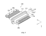
FIG. 7 is a perspective view of a secondary molded article constituting the electrical connector according to the first embodiment of the present invention.
FIG. 8 is a plan view of the secondary molded article constituting the electrical connector according to the first embodiment of the present invention.
FIG. 9 is a cross-sectional view taken along line C-C of FIG. 8.
FIG. 10 is a cross-sectional view of an electrical connector according to a second embodiment of the present invention.
DESCRIPTION OF EMBODIMENTS
Electrical connectors according to embodiments of the present invention will be described in detail below with reference to the drawings as appropriate. In the drawings, an x-axis, a y-axis, and a z-axis constitute a three-axis orthogonal coordinate system. In the following description, a positive direction of the y-axis will be referred to as a front direction, a negative direction of the y-axis as a rear direction, the direction of the x-axis as a horizontal direction, a positive direction of the z-axis as an upward direction, and a negative direction of the z-axis as a downward direction.
First Embodiment
<Configuration of Electrical Connector>
A configuration of an electrical connector 1 according to a first embodiment of the present invention will be described in detail below with reference to FIGS. 1 to 3.
The electrical connector 1 according to the present embodiment includes a housing 10, contacts 20, a front shell member 30, a rear shell member 40, an external watertight member 50, and a shielding plate 60.
The housing 10 is formed of an insulating material and holds the contacts 20. A portion of the housing 10 in close contact with the contacts 20 along the outer peripheries of the contacts 20 contains a silane coupling agent. The housing 10 contains no silane coupling agent in its rear end portion where the contacts 20 protrude to the rear. The silane coupling agent includes reaction groups chemically bondable to an inorganic material and reaction groups chemically bondable to an organic material, and has a property capable of bonding an organic material to an inorganic material.
The housing 10 includes a main body portion 11 and a plate-like portion 12.
The main body portion 11 includes a front protruding portion 111, a rear protruding portion 112, and an outward protruding portion 113. The front protruding portion 111 holds the contacts 20 and protrudes to the front. The rear protruding portion 112 protrudes to the rear. The outward protruding portion 113 lies between the front protruding portion 111 and the rear protruding portion 112, and protrudes outward compared to the front protruding portion 111 and the rear protruding portion 112. The outward protruding portion 113 includes a step portion 114.
The rear protruding portion 112 includes a front end portion 112 d, a rear end portion 112 a, and a watertight resin portion 112 c. The front end portion 112 d protrudes to the rear from the rear end of the outward protruding portion 113 and contains no silane coupling agent. The rear end portion 112 a is arranged at the rear end of the housing 10 and contains no silane coupling agent. The watertight resin portion 112 c is arranged between the front end portion 112 d and the rear end portion 112 a and contains the silane coupling agent.
The watertight resin portion 112 c is in close contact with the contacts 20 along the outer peripheries of the contacts 20. The resin constituting the watertight resin portion 112 c is of different type from that constituting the plate-like portion 12, the front protruding portion 111, the rear end portion 112 a, the front end portion 112 d, and the outward protruding portion 113. The resin has a property that its melting temperature is lower than that of the resin constituting the plate-like portion 12, the front protruding portion 111, the rear end portion 112 a, the front end portion 112 d, and the outward protruding portion 113.
For convenience of description, FIG. 3 clearly shows the boundaries between the front end portion 112 d, the rear end portion 112 a, and the watertight resin portion 112 c. In fact, the boundaries are vague since the junction between the front end portion 112 d and the watertight resin portion 112 c is melted and bonded in a manufacturing step to be described later, and the junction between the rear end portion 112 a and the watertight resin portion 112 c is melted and bonded in the manufacturing step to be described later.
The plate-like portion 12 has a plate-like shape and protrudes in front of the main body portion 11. The front end side of the plate-like portion 12 protrudes in front of the front shell member 30.
The contacts 20 are formed of a conductive material and held by the housing 10. The contacts 20 include first contacts 20 a and second contacts 20 b arranged below the first contacts 20 a. The first contacts 20 a and the second contacts 20 b are insulated from each other by the housing 10.
The first contacts 20 a each include a connection portion 21 a and a terminal portion 22 a. The connection portion 21 a is exposed on the front side of the housing 10 and exposed in a top surface of the plate-like member 12, and connects to a mating contact of a not-shown mating connector. The terminal portion 22 a protrudes behind the housing 10 and is welded to a conductive portion of a not-shown substrate. A part of the first contact 20 a between the connection portion 21 a and the terminal portion 22 a is embedded in the front protruding portion 111, the rear protruding portion 112, and the outward protruding portion 113. The first contact 20 a is in close contact with the watertight resin portion 112 c along its outer periphery. The part of the first contact 20 a in close contact with the watertight resin portion 112 c is shaped to bend horizontally and upward.
The second contacts 20 b each include a connection portion 21 b and a terminal portion 22 b. The connection portion 21 b is exposed on the front side of the housing 10 and exposed in a bottom surface of the plate-like portion 12, and connects to a mating contact of the not-shown mating connector. The terminal portion 22 b protrudes behind the housing 10 and is welded to the not-shown substrate. A part of the second contact 20 b between the connection portion 21 b and the terminal portion 22 b is embedded in the front protruding portion 111, the rear protruding portion 112, and the outward protruding portion 113. The second contact 20 b is in close contact with the watertight resin portion 112 c along its outer periphery. The part of the second contact 20 b in close contact with the watertight resin portion 112 c is shaped to bend horizontally and downward. The lower ends of the terminal portions 22 a and the lower ends of the terminal portions 22 b are vertically at the same height.
The front shell member 30 is formed of a conductive material and has a cylindrical shape extending in a front-to-rear direction. The front shell member 30 includes a fitting portion 31 to which the not-shown mating connector can be fitted from the front. The plate-like portion 12 and the front protruding portion 111 are arranged in the fitting portion 31. The rear end of the front shell member 30 is in contact with the step portion 114 and held on the front side of the outward protruding portion 113.
The rear shell member 40 is made of a conductive material and has a cylindrical shape extending in the front-to-rear direction. The rear shell member 40 includes a large diameter portion 41 and a small diameter portion 42, and has a narrowed shape toward the rear. The large diameter portion 41 is held on the rear side of the outward protruding portion 113. The small diameter portion 42 is continuously formed behind the large diameter portion 41, and has a diameter smaller than that of the large diameter portion 41. The small diameter portion 42 is in close contact with the watertight resin portion 112 c along its inner periphery.
The external watertight member 50 is formed of an elastic insulating material in an annular shape, and arranged at the front end of the front shell member 30.
The shielding plate 60 is formed of a conductive material and has a plate-like shape. The shielding plate 60 is embedded in the housing 10. The shielding plate 60 is arranged between the first contacts 20 a and the second contacts 20 b in a state of being insulated from the first contacts 20 a and the second contacts 20 b.
<Method for Manufacturing Electrical Connector>
A method for manufacturing the electrical connector 1 according to the first embodiment of the present invention will be described in detail below with reference to FIGS. 1 to 9.
The contacts 20 and the shielding plate 60 formed in advance are initially set in a not-shown mold. A resin containing no silane coupling agent is injected into the mold at a predetermined injection molding temperature, followed by curing. By such integral molding, a primary molded article 100 shown in FIGS. 4 to 6 is formed. The primary molded article 100 includes the plate-like portion 12, the contacts 20, the front protruding portion 111, the outward protruding portion 113, the front end portion 112 d, the rear end portion 112 a, and the shielding plate 60. An example of the injection molding temperature is 300° C.
The primary molded particle 100 has a space 112 b between the front end portion 112 d and the rear end portion 112 a. The front end portion 112 d and the rear end portion 112 a are opposed to each other. In the space 112 b, part of the first contacts 20 a and part of the second contacts 20 b are exposed to outside.
Next, the primary molded article 100 is set in a not-shown mold. A resin containing the silane coupling agent is injected into the space 112 b at a predetermined temperature, followed by curing. By such integral molding, a secondary molded article 150 shown in FIGS. 7 to 9 is formed. The secondary molded article 150 includes the primary molded article 100 and the watertight resin portion 112 c. In other words, the secondary molded article 150 is configured by adding the watertight resin portion 112 c to the primary molded article 100.
The resin poured into the space 112 b is of different type from that constituting the plate-like portion 12, the front protruding portion 111, the rear end portion 112 a, the front end portion 112 d, and the outward protruding portion 113 of the primary molded article 100. The resin has a property that its melting point is lower than that of the resin constituting the plate-like portion 12, the front protruding portion 111, the rear end portion 112 a, the front end portion 112 d, and the outward protruding portion 113 of the primary molded article 100. The temperature in forming the secondary molded article 150 is thus set to be lower than the injection molding temperature in forming the primary molded article 100. An example of the temperature in molding the secondary molded article 150 is 150° C.
Since the temperature in forming the secondary molded article 150 is set to be lower than the injection molding temperature, the resin constituting the plate-like portion 12, the front protruding portion 111, the rear end portion 112 a, the front end portion 112 d, and the outward protruding portion 113 will not melt when the secondary molded article 150 is formed. In forming the secondary molded article 150, the contacts 20 can thus be securely held by the plate-like portion 12, the front protruding portion 111, the rear end portion 112 a, the front end portion 112 d, and the outward protruding portion 113. In particular, the contacts 20 can be securely held by the rear end portion 112 a. The protruding positions of the terminal portions 22 a and 22 b from the rear end portion 112 a can thus be prevented from shifting when the secondary molded article 150 is formed. This can prevent poor connection of the terminal portions 22 a and 22 b with the conductive portions of the substrate.
Next, the secondary molded article 150 is covered with the front shell member 30 from the front and covered with the rear shell member 40 from behind.
Next, the front shell member 30 and the rear shell member 40 are attached to the secondary molded article 150 by welding the rear end of the front shell member 30 and the front end of the rear shell member 40.
Next, the external watertight member 50 is attached to the front end of the front shell member 30.
Next, the secondary molded article 150 to which the front shell member 30 and the rear shell member 40 are attached is heated to a temperature higher than that in forming the watertight resin portion 112 c, whereby the watertight resin portion 112 c is melted again. The temperature to which the secondary molded article 150 having the front shell member 30 and the rear shell member 40 attached thereto is heated may be the same as or different from the injection molding temperature in forming the primary molded article 100.
Here, the part of the watertight resin portion 112 c in contact with the outer peripheries of the contacts 20 is melted and bonded to the outer peripheries of the contacts 20 by the bonding action of the silane coupling agent contained in the watertight resin portion 112 c. The part of the watertight resin portion 112 c in contact with the inner periphery of the rear shell member 40 is melted and bonded to the inner periphery of the rear shell member 40 by the bonding action of the silane coupling agent contained in the watertight resin portion 112 c. The watertight resin portion 112 c and the outer peripheries of the contacts 20 are thereby put in close contact with each other, and the watertight resin portion 112 c and the inner periphery of the rear shell member 40 are put in close contact with each other.
Heating the secondary molded article 150 to which the front shell member 30 and the rear shell member 40 are attached to a temperature higher than that in forming the watertight resin portion 112 c can melt at least the watertight resin portion 112 c again, whereby the watertight resin portion 112 c can be firmly adhered to the rear end portion 112 a and the front end portion 112 d.
The watertight resin portion 112 c thus has adhesiveness to the contacts 20 made of metal and the rear and front end portions 112 a and 112 d made of a resin material.
Next, the secondary molded article 150 to which the front shell member 30 and the rear shell member 40 are attached is cooled to complete the electrical connector 1.
In the electrical connector 1 manufactured by the foregoing manufacturing method, the watertight resin portion 112 c containing the silane coupling agent makes close contact with the outer peripheries of the contacts 20 to seal the gaps between the watertight resin portion 112 c and the contacts 20. The interior of an electronic device to which the electrical connector 1 is attached can thus be sealed off from the gaps between the housing 10 and the contacts 20 and made watertight. In the electrical connector 1, the watertight resin portion 112 c containing the silane coupling agent makes close contact with the inner periphery of the rear shell member 40 to seal the gap between the watertight resin portion 112 c and the rear shell member 40. The interior of the electronic device to which the electrical connector 1 is attached can thus be sealed off from the gap between the housing 10 and the rear shell member 40 and made watertight.
In the foregoing manufacturing method, the watertight resin portion 112 c is formed before the front shell member 30 and the rear shell member 40 are provided. However, the front shell member 30 and the rear shell member 40 may be provided before the formation of the watertight resin portion 112 c. A resin containing the silane coupling agent may be injected into the space 112 b through a gap of the rear shell member 40 and then heated to form the watertight resin portion 112 c.
As described above, according to the present embodiment, a portion of the housing 10 in close contact with the contacts 20 along the outer peripheries of the contacts 20 contains the silane coupling agent. The gaps between the housing 10 and the contacts 20 can thus be made watertight. This can eliminate the need for elastic parts and potting agents for sealing to simplify assembly. An increase in manufacturing cost can be suppressed as well.
According to the present embodiment, a portion of the housing 10 in close contact with the rear shell member 40 along the inner periphery of the rear shell member 40 contains the silane coupling agent. The gap between the housing 10 and the rear shell member 40 can thus be made watertight. This can simplify assembly and suppress an increase in manufacturing cost.
While the present embodiment includes the external watertight member 50, the external watertight member 50 does not need to be provided.
In the present embodiment, two types of contacts, namely, the first contacts 20 a and the second contacts 20 b are arranged on the housing 10. However, one type of contacts may be arranged on the housing.
While the present embodiment includes the shielding plate 60, the shielding plate 60 does not need to be provided.
In the present embodiment, the housing 10 may have any shape as long as the silane coupling agent-containing part of the housing makes close contact along the outer peripheries of the contacts 20 and makes close contact along the inner periphery of the rear shell member 40.
In the present embodiment, the front shell member 30 and the rear shell member 40 are formed of a conductive material. However, either one or both of the front and rear shell members 30 and 40 may be formed of an insulating material.
In the present embodiment, the shell member includes two members, namely, the front shell member 30 and the rear shell member 40. However, the shell member may be configured as a single member.
Second Embodiment
<Configuration of Electrical Connector>
A configuration of an electrical connector 2 according to a second embodiment of the present invention will be described in detail below with reference to FIG. 10.
The electrical connector 2 according to the present embodiment includes a housing 210, contacts 220, and a shell member 230.
The housing 210 is formed of an insulating material and holds the contacts 220. The housing 210 contains a silane coupling agent in its watertight resin portion R1 which is a portion to make close contact with the contacts 220 along the outer peripheries of the contacts 220. The housing 210 includes a plate-like portion 212 of plate-like shape protruding to the front.
The contacts 220 are formed of a conductive material and held by the housing 210. The contacts 220 each include a connection portion 221 and a terminal portion 222. The connection portion 221 is exposed to the front and exposed in a top surface of the plate-like portion 212. The connection portion 221 connects to a mating contact of a not-shown mating connector. The terminal portion 222 protrudes behind the housing 210 and is welded to a conductive portion of a not-shown substrate. A part of the contact 220 between the connection portion 221 and the terminal portion 222 is embedded in the housing 210 and makes close contact with the portion R1.
The shell member 230 is formed of a conductive material and has a cylindrical shape extending in a front-to-rear direction. The shell member 230 includes a fitting part 231 in which the plate-like portion 212 is arranged and to which the not-shown mating connector can be fitted from the front. The rear end of the shell member 230 is held by the housing 210.
<Method for Manufacturing Electrical Connector>
A method for manufacturing the electrical connector 2 according to the second embodiment of the present invention will be described in detail below.
Initially, the contacts 220 and the watertight resin portion R1 containing the silane coupling agent are integrally molded at a predetermined temperature to form a primary molded article. An example of the predetermined temperature is 150° C.
Next, the primary molded article and the shell member 230 are set in a not-shown mold. A resin containing no silane coupling agent is injected into the mold at a predetermined injection molding temperature, followed by curing. By such integral molding, the electrical connector 2 is formed. An example of the injection molding temperature is 300° C.
The injection molding temperature is higher than the predetermined temperature in forming the foregoing primary molded article. The part of the watertight resin portion R1 in contact with the outer peripheries of the contacts 220 is thus melted again and bonded to the outer peripheries of the contacts 220 by the bonding action of the silane coupling agent contained in the watertight resin portion R1. The watertight resin portion R1 and the outer peripheries of the contacts 220 are thereby put in close contact with each other. Melting the watertight resin portion R1 again firmly adheres the watertight resin portion R1 to the portions of the housing 210 other than the watertight resin portion R1.
The watertight resin portion R1 thus has adhesiveness to the metal contacts 220 and the portions of the resin housing 210 other than the watertight resin portion R1.
In the electrical connector 2 manufactured by the foregoing manufacturing method, the watertight resin portion R1 containing the silane coupling agent makes close contact with the outer peripheries of the contacts 220 to seal the gaps between the watertight resin portions R1 and the contacts 220. The interior of an electronic device to which the electrical connector 2 is attached can thus be sealed off from the gaps between the housing 210 and the contacts 220 and made watertight.
As described above, according to the present embodiment, the portion of the housing 210 in close contact with the contacts 220 along the outer peripheries of the contacts 220 contains the silane coupling agent. The gaps between the housing 210 and the contacts 220 can thus be made watertight. This can eliminate the need for elastic parts and potting agents for sealing to simplify assembly. An increase in manufacturing cost can be suppressed as well.
According to the present embodiment, the watertight resin portion R1 can provide the watertight effect in the step of integrally molding the primary molded article and the shell member 230. Such a configuration can simplify the assembly steps to facilitate manufacturing, with a reduction in manufacturing cost.
The present invention is not limited to the foregoing embodiments in terms of the types, arrangement, numbers, or the like of the members. It will be understood that appropriate modifications may be made without departing from the gist of the invention. For example, the components may be replaced with ones having similar operations and effects as appropriate.
The embodiment of the present invention is suitable for an electrical connector having a watertight function and a method for manufacturing the electrical connector.
REFERENCE SIGNS LIST
-
- 1 electrical connector
- 2 electrical connector
- 10 housing
- 11 main body portion
- 12 plate-like portion
- 20 contact
- 20 a first contact
- 20 b second contact
- 21 a connection portion
- 21 b connection portion
- 22 a terminal portion
- 22 b terminal portion
- 30 front shell member
- 31 fitting portion
- 40 rear shell member
- 41 large diameter portion
- 42 small diameter portion
- 50 external watertight member
- 60 shielding plate
- 100 primary molded article
- 111 front protruding portion
- 112 rear protruding portion
- 112 a rear end portion
- 112 b space
- 112 c watertight resin portion
- 112 d front end portion
- 113 outward protruding portion
- 114 step portion
- 150 secondary molded article
- 210 housing
- 212 plate-like portion
- 220 contact
- 221 connection portion
- 222 terminal portion
- 230 shell member
- 231 fitting part
- R1 watertight resin portion