US10074198B2 - Methods and apparatuses for image processing and display - Google Patents
Methods and apparatuses for image processing and display Download PDFInfo
- Publication number
- US10074198B2 US10074198B2 US15/085,526 US201615085526A US10074198B2 US 10074198 B2 US10074198 B2 US 10074198B2 US 201615085526 A US201615085526 A US 201615085526A US 10074198 B2 US10074198 B2 US 10074198B2
- Authority
- US
- United States
- Prior art keywords
- region
- image
- configuration setting
- anatomical
- merged
- Prior art date
- Legal status (The legal status is an assumption and is not a legal conclusion. Google has not performed a legal analysis and makes no representation as to the accuracy of the status listed.)
- Active, expires
Links
Images


Classifications
-
- G—PHYSICS
- G16—INFORMATION AND COMMUNICATION TECHNOLOGY [ICT] SPECIALLY ADAPTED FOR SPECIFIC APPLICATION FIELDS
- G16H—HEALTHCARE INFORMATICS, i.e. INFORMATION AND COMMUNICATION TECHNOLOGY [ICT] SPECIALLY ADAPTED FOR THE HANDLING OR PROCESSING OF MEDICAL OR HEALTHCARE DATA
- G16H30/00—ICT specially adapted for the handling or processing of medical images
- G16H30/40—ICT specially adapted for the handling or processing of medical images for processing medical images, e.g. editing
-
- G06T11/005—
-
- A—HUMAN NECESSITIES
- A61—MEDICAL OR VETERINARY SCIENCE; HYGIENE
- A61B—DIAGNOSIS; SURGERY; IDENTIFICATION
- A61B6/00—Apparatus or devices for radiation diagnosis; Apparatus or devices for radiation diagnosis combined with radiation therapy equipment
- A61B6/52—Devices using data or image processing specially adapted for radiation diagnosis
- A61B6/5211—Devices using data or image processing specially adapted for radiation diagnosis involving processing of medical diagnostic data
- A61B6/5217—Devices using data or image processing specially adapted for radiation diagnosis involving processing of medical diagnostic data extracting a diagnostic or physiological parameter from medical diagnostic data
-
- A—HUMAN NECESSITIES
- A61—MEDICAL OR VETERINARY SCIENCE; HYGIENE
- A61B—DIAGNOSIS; SURGERY; IDENTIFICATION
- A61B6/00—Apparatus or devices for radiation diagnosis; Apparatus or devices for radiation diagnosis combined with radiation therapy equipment
- A61B6/52—Devices using data or image processing specially adapted for radiation diagnosis
- A61B6/5211—Devices using data or image processing specially adapted for radiation diagnosis involving processing of medical diagnostic data
- A61B6/5229—Devices using data or image processing specially adapted for radiation diagnosis involving processing of medical diagnostic data combining image data of a patient, e.g. combining a functional image with an anatomical image
- A61B6/5235—Devices using data or image processing specially adapted for radiation diagnosis involving processing of medical diagnostic data combining image data of a patient, e.g. combining a functional image with an anatomical image combining images from the same or different ionising radiation imaging techniques, e.g. PET and CT
-
- A—HUMAN NECESSITIES
- A61—MEDICAL OR VETERINARY SCIENCE; HYGIENE
- A61B—DIAGNOSIS; SURGERY; IDENTIFICATION
- A61B8/00—Diagnosis using ultrasonic, sonic or infrasonic waves
- A61B8/52—Devices using data or image processing specially adapted for diagnosis using ultrasonic, sonic or infrasonic waves
- A61B8/5215—Devices using data or image processing specially adapted for diagnosis using ultrasonic, sonic or infrasonic waves involving processing of medical diagnostic data
- A61B8/5223—Devices using data or image processing specially adapted for diagnosis using ultrasonic, sonic or infrasonic waves involving processing of medical diagnostic data for extracting a diagnostic or physiological parameter from medical diagnostic data
-
- A—HUMAN NECESSITIES
- A61—MEDICAL OR VETERINARY SCIENCE; HYGIENE
- A61B—DIAGNOSIS; SURGERY; IDENTIFICATION
- A61B8/00—Diagnosis using ultrasonic, sonic or infrasonic waves
- A61B8/52—Devices using data or image processing specially adapted for diagnosis using ultrasonic, sonic or infrasonic waves
- A61B8/5215—Devices using data or image processing specially adapted for diagnosis using ultrasonic, sonic or infrasonic waves involving processing of medical diagnostic data
- A61B8/5238—Devices using data or image processing specially adapted for diagnosis using ultrasonic, sonic or infrasonic waves involving processing of medical diagnostic data for combining image data of patient, e.g. merging several images from different acquisition modes into one image
- A61B8/5246—Devices using data or image processing specially adapted for diagnosis using ultrasonic, sonic or infrasonic waves involving processing of medical diagnostic data for combining image data of patient, e.g. merging several images from different acquisition modes into one image combining images from the same or different imaging techniques, e.g. color Doppler and B-mode
-
- G—PHYSICS
- G06—COMPUTING OR CALCULATING; COUNTING
- G06T—IMAGE DATA PROCESSING OR GENERATION, IN GENERAL
- G06T12/00—Tomographic reconstruction from projections
- G06T12/10—Image preprocessing, e.g. calibration, positioning of sources or scatter correction
-
- G—PHYSICS
- G06—COMPUTING OR CALCULATING; COUNTING
- G06T—IMAGE DATA PROCESSING OR GENERATION, IN GENERAL
- G06T5/00—Image enhancement or restoration
- G06T5/50—Image enhancement or restoration using two or more images, e.g. averaging or subtraction
-
- A—HUMAN NECESSITIES
- A61—MEDICAL OR VETERINARY SCIENCE; HYGIENE
- A61B—DIAGNOSIS; SURGERY; IDENTIFICATION
- A61B6/00—Apparatus or devices for radiation diagnosis; Apparatus or devices for radiation diagnosis combined with radiation therapy equipment
- A61B6/46—Arrangements for interfacing with the operator or the patient
- A61B6/467—Arrangements for interfacing with the operator or the patient characterised by special input means
-
- A—HUMAN NECESSITIES
- A61—MEDICAL OR VETERINARY SCIENCE; HYGIENE
- A61B—DIAGNOSIS; SURGERY; IDENTIFICATION
- A61B6/00—Apparatus or devices for radiation diagnosis; Apparatus or devices for radiation diagnosis combined with radiation therapy equipment
- A61B6/56—Details of data transmission or power supply, e.g. use of slip rings
- A61B6/563—Details of data transmission or power supply, e.g. use of slip rings involving image data transmission via a network
-
- A—HUMAN NECESSITIES
- A61—MEDICAL OR VETERINARY SCIENCE; HYGIENE
- A61B—DIAGNOSIS; SURGERY; IDENTIFICATION
- A61B8/00—Diagnosis using ultrasonic, sonic or infrasonic waves
- A61B8/46—Ultrasonic, sonic or infrasonic diagnostic devices with special arrangements for interfacing with the operator or the patient
- A61B8/467—Ultrasonic, sonic or infrasonic diagnostic devices with special arrangements for interfacing with the operator or the patient characterised by special input means
-
- A—HUMAN NECESSITIES
- A61—MEDICAL OR VETERINARY SCIENCE; HYGIENE
- A61B—DIAGNOSIS; SURGERY; IDENTIFICATION
- A61B8/00—Diagnosis using ultrasonic, sonic or infrasonic waves
- A61B8/56—Details of data transmission or power supply
- A61B8/565—Details of data transmission or power supply involving data transmission via a network
-
- G—PHYSICS
- G06—COMPUTING OR CALCULATING; COUNTING
- G06T—IMAGE DATA PROCESSING OR GENERATION, IN GENERAL
- G06T2207/00—Indexing scheme for image analysis or image enhancement
- G06T2207/20—Special algorithmic details
- G06T2207/20212—Image combination
- G06T2207/20221—Image fusion; Image merging
-
- G—PHYSICS
- G06—COMPUTING OR CALCULATING; COUNTING
- G06T—IMAGE DATA PROCESSING OR GENERATION, IN GENERAL
- G06T2207/00—Indexing scheme for image analysis or image enhancement
- G06T2207/30—Subject of image; Context of image processing
- G06T2207/30004—Biomedical image processing
-
- G—PHYSICS
- G16—INFORMATION AND COMMUNICATION TECHNOLOGY [ICT] SPECIALLY ADAPTED FOR SPECIFIC APPLICATION FIELDS
- G16H—HEALTHCARE INFORMATICS, i.e. INFORMATION AND COMMUNICATION TECHNOLOGY [ICT] SPECIALLY ADAPTED FOR THE HANDLING OR PROCESSING OF MEDICAL OR HEALTHCARE DATA
- G16H50/00—ICT specially adapted for medical diagnosis, medical simulation or medical data mining; ICT specially adapted for detecting, monitoring or modelling epidemics or pandemics
- G16H50/20—ICT specially adapted for medical diagnosis, medical simulation or medical data mining; ICT specially adapted for detecting, monitoring or modelling epidemics or pandemics for computer-aided diagnosis, e.g. based on medical expert systems
Definitions
- Example embodiments of the present invention relate generally to methods, systems, and computer readable storage media for processing medical images and, more particularly, to methods, systems, and computer readable media for generating merged images having multiple regions associated with different configuration settings.
- Clinical analysis and diagnosis using medical images requires careful control and manipulation of view settings associated with particular image types.
- X-rays, ultrasounds, computerized tomography (CT) scans, and other medical image capture techniques require the use of carefully selected view configuration settings based upon the image capturing technique (e.g., the particular technology or device used to capture the image), the viewing angle (e.g., a front view or lateral view of the patient's anatomy), the particular portion of patient anatomy being imaged (e.g., torso, head, arm, leg), and the particular anatomical element desired to be viewed (e.g., viewing an image to diagnose a problem in the patient's lung may require different image view configuration settings than viewing a patient's heart).
- the image capturing technique e.g., the particular technology or device used to capture the image
- the viewing angle e.g., a front view or lateral view of the patient's anatomy
- the particular portion of patient anatomy being imaged e.g., torso, head, arm, leg
- an image may include both the patient's heart and lungs, but brightness and contrast settings used to visualize the lungs may result in a loss of visual fidelity in a region of the image corresponding to the heart, and vice-versa.
- merged images having a plurality of regions associated with different viewer configuration settings.
- These merged images may exist as separate images, or within a viewport defined within a medical image viewing application.
- Regions are defined based on the presence of particular anatomical elements, such that each region is associated with one or more anatomical elements.
- Anatomical elements may be detected by various processes and algorithms, and regions within the image are defined to encompass or otherwise be associated with those anatomical elements.
- Embodiments may further include a database or table comprising configuration settings for particular anatomical elements, such that detected anatomical elements are mapped to configuration settings stored in the database, and those configuration settings are applied to regions of the image corresponding to the anatomical elements.
- An example of an embodiment includes a method for implementing improved image processing techniques.
- the method includes receiving a source image, programmatically identifying a plurality of anatomical elements within the source image through use of a computer vision technique, determining a first region of the source image corresponding to a first anatomical element of the plurality of anatomical elements, determining a second region of the source image corresponding to a second anatomical element of the plurality of anatomical elements, applying at least one first configuration setting to the first region, applying at least one second configuration setting to the second region, the at least one second configuration setting different from the at least one first configuration setting, and generating a merged image, wherein the merged image comprises the first region as visualized according to the at least one first configuration setting and the second region as visualized according to the at least one second configuration setting.
- the method includes determining a type of the first anatomical element using the computer vision technique, and selecting the at least one first configuration setting based at least in part on the type of the first anatomical element. Selecting the at least one first configuration setting based at least in part on the type of the first anatomical element comprises looking up the type of the first anatomical element in a database of configuration settings.
- the method may also include displaying the merged image in an interface, wherein the interface comprises at least one interface control associated with each of the first region and the second region, receiving a selection of an interface control associated with the first region, and in response to receiving the selection of the interface control associated with the first region, applying the at least one configuration setting to the entire merged image.
- the at least one first configuration setting may include at least one of a brightness setting, a contrast setting, or a color correction setting.
- Generating the merged image may include outputting the merged image via a viewer application.
- the image may be output via a Picture Archiving and Communications System.
- the source image may be a Digital Imaging and Communications in Medicine image.
- the method may include storing the merged image in a memory.
- the method may include storing data defining the first region and the second region and the data defining the configuration settings associated with the first region and the second region as metadata for the merged image.
- the apparatus includes a processor and a memory.
- the memory stores instructions that are executed by the processor to configure the apparatus to receive a source image, programmatically identify a plurality of anatomical elements within the source image through use of a computer vision technique, determine a first region of the source image corresponding to a first anatomical element of the plurality of anatomical elements, determine a second region of the source image corresponding to a second anatomical element of the plurality of anatomical elements, apply at least one first configuration setting to the first region, apply at least one second configuration setting to the second region, the at least one second configuration setting different from the at least one first configuration setting, and generate a merged image, wherein the merged image comprises the first region as visualized according to the at least one first configuration setting and the second region as visualized according to the at least one second configuration setting.
- the apparatus is further configured to determine a type of the first anatomical element using the computer vision technique, and select the at least one first configuration setting based at least in part on the type of the first anatomical element. Selecting the at least one first configuration setting based at least in part on the type of the first anatomical element may include looking up the type of the first anatomical element in a database of configuration settings.
- the apparatus may be further configured to display the merged image in an interface, wherein the interface comprises at least one interface control associated with each of the first region and the second region, receive a selection of an interface control associated with the first region, and in response to receiving the selection of the interface control associated with the first region, apply the at least one configuration setting to the entire merged image.
- the at least one first configuration setting may include at least one of a brightness setting, a contrast setting, or a color correction setting.
- Generating the merged image may include outputting the merged image via a viewer application.
- the image may be output via a Picture Archiving and Communications System.
- the source image may be a Digital Imaging and Communications in Medicine image.
- the apparatus may be further configured to store the merged image in a memory.
- Another example of an embodiment includes a non-transitory computer readable storage medium comprising instructions that, when executed by a processor, cause the processor to implement improved image processing techniques.
- the instructions configure the processor to receive a source image, programmatically identify a plurality of anatomical elements within the source image through use of a computer vision technique, determine a first region of the source image corresponding to a first anatomical element of the plurality of anatomical elements, determine a second region of the source image corresponding to a second anatomical element of the plurality of anatomical elements, apply at least one first configuration setting to the first region, apply at least one second configuration setting to the second region, the at least one second configuration setting different from the at least one first configuration setting, and generate a merged image, wherein the merged image comprises the first region as visualized according to the at least one first configuration setting and the second region as visualized according to the at least one second configuration setting.
- FIG. 1 is a block diagram of an apparatus for providing improved image processing and display in accordance with some embodiments of the present invention
- FIG. 2 is an illustration of a data flow for generating a merged medical image in accordance with some embodiments of the present invention
- FIG. 3A is an illustration of a source medical image which may function as input to a system for providing improved image processing and display in accordance with some embodiments of the present invention
- FIG. 3B is an illustration of a merged medical image function which may result as output from a system for providing improved image processing and display in accordance with some embodiments of the present invention.
- FIG. 4 is an illustration of a flow diagram illustrating an example of a process for generating a merged image in accordance with embodiments of the present invention.
- a method, apparatus and computer program product are provided in accordance with example embodiments of the present invention to provide improved systems for processing and displaying images.
- present systems for visualizing medical images are inadequate.
- the inventors have developed a system that generates merged images that include multiple regions that are displayed according to configuration settings associated with anatomical elements identified within those multiple regions.
- embodiments of the present invention are operable to identify regions of a source image associated with particular anatomical elements, select configuration settings for those regions based at least in part on those identified anatomical elements, and generate a merged image such that the regions associated with each anatomical element have corresponding configuration settings.
- These configuration settings may include, for example, brightness levels, contrast levels, color correction settings, and the like.
- source image and “source medical image” should be understood to refer to any source set of image data, including but not limited to images stored in a Digital Imaging and Communications in Medicine (DICOM) format.
- the source medical image may have a set of configuration settings applied for viewing, or the source medical image may refer to an image prior to the application of configuration settings or other adjustments applied within a viewer application.
- DICOM Digital Imaging and Communications in Medicine
- configuration settings should be understood to refer to settings or changes that are applied to a set of image data to display that image within a viewer application.
- the term should be understood to include brightness, contrast, color balance, and other settings that may be applied to the image to control the manner in which that image is displayed within the viewer application.
- merged image should be understood to refer to an output image including image data that is generated from a source image having different configuration settings applied to two or more regions identified within the source image.
- the merged image may include additional data identifying the particular regions, the anatomical elements identified within the image, and/or the configuration settings used to generate the image, though the definition of merged image should also be understood to encompass images generated using a plurality of configuration settings but which do not include such data. It should be appreciated that the term “merged image” is used to refer to an image that is generated through the merger of different configuration settings applied to different regions of the image.
- source images may include a series of images processed together (e.g., CT scan images that layer a plurality of images over one another), such an image would not qualify as a “merged image” under the definition used throughout this application unless those series of images also included two or more regions with different configuration settings applied.
- anatomical element should be understood to refer to any feature of human anatomy, surgical instrument, implant, or the like that may be identified within a medical image.
- medical image refers to any image captured as part of a medical imaging operation including, without limitation, CT scans, x-rays, ultrasounds, magnetic resonance imaging (MRI) operations, positron emission tomography (PET) scans, or the like.
- CT scans CT scans
- x-rays ultrasounds
- MRI magnetic resonance imaging
- PET positron emission tomography
- FIG. 1 illustrates a block diagram of an apparatus 100 in accordance with some example embodiments.
- the apparatus 100 may be any computing device capable of implementing improved techniques for image processing and visualization as described herein.
- the apparatus 100 may be implemented as a computing device executing one or more applications for receiving, processing, and outputting images.
- the apparatus 100 implements hardware and software that serves to receive source image data, identify regions of the source image that correspond to anatomical elements, determine configuration settings for those regions based on the determined anatomical elements, apply the determined configuration settings to their corresponding regions, and generate a merged image that represents the application of the determined configuration settings to the source image.
- the apparatus 100 may be implemented as a standalone or rack-mounted server, a desktop computer, a laptop computer, a personal digital assistant, a tablet computer, a netbook computer, a mobile device, a Picture Archive and Communications System (PACS) workstation or the like. Accordingly, it will be appreciated that the apparatus 100 may comprise devices, hardware, and the like configured to implement and/or otherwise support implementation of various example embodiments described herein.
- PACS Picture Archive and Communications System
- an apparatus 100 may include a processor 102 , a memory 104 , input/output circuitry 106 , communications circuitry 108 , image analysis circuitry 110 , image editing circuitry 112 , and image output circuitry 114 .
- the apparatus 100 may be configured to utilize the source image described below with respect to FIG. 3A , generate the merged image described below with respect to FIG. 3B , and to execute the operations described below with respect to FIGS. 2 and 4 .
- these components 102 - 114 are described with respect to functional limitations, it should be understood that the particular implementations necessarily include the use of particular hardware. It should also be understood that certain of these components 102 - 114 may include similar or common hardware.
- circuitry may both leverage use of the same processor, network interface, storage medium, or the like to perform their associated functions, such that duplicate hardware is not required for each set of circuitry.
- circuitry as used herein with respect to components of the apparatus should therefore be understood to include particular hardware configured to perform the functions associated with the particular circuitry as described herein.
- circuitry should be understood broadly to include hardware and, in some embodiments, software for configuring the hardware.
- circuitry includes processing circuitry, storage media, network interfaces, input/output devices, and/or the like.
- other elements of the apparatus 100 may provide or supplement the functionality of particular circuitry.
- the processor 102 may provide processing functionality
- the memory 104 may provide storage functionality
- the communications circuitry 108 may provide network interface functionality, and the like, such that each of the circuitries may be formed by other circuitry components of the apparatus 100 .
- the processor 102 may be in communication with the memory 104 via a bus for passing information among components of the apparatus.
- the memory 104 may be non-transitory and may include, for example, one or more volatile and/or non-volatile memories.
- the memory may be an electronic storage device (e.g., a computer readable storage medium).
- the memory 104 may be configured to store information, data, content, applications, instructions, tables, data structures, or the like, for enabling the apparatus to carry out various functions in accordance with example embodiments of the present invention.
- the processor 102 may include various processing devices and may, for example, include one or more processing devices configured to perform independently from one another. Additionally or alternatively, the processor may include one or more processors configured in tandem via a bus to enable independent execution of instructions, pipelining, and/or multithreading.
- processing circuitry may be understood to include a single core processor, a multi-core processor, multiple processors internal to the apparatus, and/or remote or “cloud” processors.
- the processor 102 may be configured to execute instructions stored in the memory 104 or otherwise accessible to the processor.
- the processor may be configured to execute hard-coded functionality.
- the processor may represent an entity (e.g., physically embodied in circuitry) capable of performing operations according to an embodiment of the present invention while configured accordingly.
- the processor when the processor is embodied as an executor of software instructions, and the instructions may specifically configure the processor to perform the algorithms and/or operations described herein when the instructions are executed.
- the apparatus 100 may include input/output circuitry 106 that may, in turn, be in communication with the processor 102 to provide output to the user and, in some embodiments, to receive an indication of a user input.
- the input/output circuitry 106 may comprise a user interface and may include a display and may comprise a web user interface, a mobile application, a client device, a kiosk, or the like.
- the input/output circuitry 106 may also include a keyboard, a mouse, a joystick, a touch screen, touch areas, soft keys, a microphone, a speaker, or other input/output mechanisms.
- the processor and/or user interface circuitry comprising the processor may be configured to control one or more functions of one or more user interface elements through computer program instructions (e.g., software and/or firmware) stored on a memory accessible to the processor (e.g., memory 104 , and/or the like).
- the input/output circuitry 106 may provide a mechanism for display of a merged image (e.g., via a monitor or other display), and receiving input related to an image viewing interface (e.g., a mouse, keyboard, or the like).
- the communications circuitry 108 may be any means such as a device or circuitry embodied in either hardware or a combination of hardware and software that is configured to receive and/or transmit data from/to a network and/or any other device, circuitry, or module in communication with the apparatus 100 .
- the communications circuitry 108 may include, for example, a network interface for enabling communications with a wired or wireless communication network.
- the communications circuitry 108 may include one or more network interface cards, antennae, buses, switches, routers, modems, and supporting hardware and/or software, or any other device suitable for enabling communications via a network.
- the communication interface may include the circuitry for interacting with the antenna(s) to cause transmission of signals via the antenna(s) or to handle receipt of signals received via the antenna(s).
- the image analysis circuitry 110 includes hardware configured to receive and/or generate a source image and analyze the image to identify regions of the image associated with particular anatomical elements.
- the image analysis circuitry 110 may include one or more application specific interface circuits designed to or a configured processor, such as the processor 102 , programmed with one or more image analysis algorithms to identify regions of a source image that correspond to one or more anatomical elements. This identification process may include associating particular pixels or borders identifying pixel regions with those particular anatomical elements.
- the image analysis circuitry 110 may implement or utilize image atlasing algorithms, image segmentation capabilities, or the like, such as the various image analysis libraries offered by Toshiba Medical Systems.
- the image editing circuitry 112 includes hardware configured to adjust configuration settings or otherwise edit a source image to produce a merged output image.
- the image editing circuitry 112 includes one or more ASICs or configured processors that are configured to apply configuration settings, such as brightness and/or contrast settings, to a source image.
- configuration settings such as brightness and/or contrast settings
- the image editing circuitry 112 may apply the brightness and contrast settings to adjust the intensity of particular pixels within the source image.
- the particular brightness and contrast settings may be selected for each pixel based on whether that pixel corresponds to a region of the image in which a particular anatomical element was identified by the image analysis circuitry 110 .
- the image editing circuitry 112 may, in some embodiments, implement part or all of an image viewing application such that the image editing circuitry edits a set of data within the viewer application to implement the configuration settings. Alternatively, in some embodiments the image editing circuitry 112 may generate a merged image as output to be stored for use by an image viewing application implemented externally to the image editing circuitry 112 . In this manner, the merged image may be stored for use with any image viewer that is capable of accessing the archive in which the image is stored.
- the image output circuitry 114 includes hardware configured to display a merged image such as generated by the image editing circuitry 112 .
- the image output circuitry 114 includes one or more ASICs or configured processors that serve to implement an image viewer application that provides an interface for output of the merged image via a display or transmission to a remote computer for display.
- the image output circuitry 114 may include, for example, an image viewing component of a PACS workstation that allows a user to view the merged medical image in the context of a medical imaging study.
- the image output circuitry 114 may utilize one or more components of the input/output circuitry 106 to provide these functions.
- any computer program instructions and/or other type of code may be loaded onto a computer, processor or other programmable apparatus's circuitry to produce a machine, such that the computer, processor other programmable circuitry that execute the code on the machine create the means for implementing various functions, including those described herein.
- embodiments of the present invention may be configured as methods, mobile devices, backend network devices, and the like. Accordingly, embodiments may comprise various means including entirely of hardware or any combination of software and hardware. Furthermore, embodiments may take the form of a computer program product on at least one non-transitory computer-readable storage medium having computer-readable program instructions (e.g., computer software) embodied in the storage medium. Any suitable computer-readable storage medium may be utilized including non-transitory hard disks, CD-ROMs, flash memory, optical storage devices, or magnetic storage devices.
- FIG. 2 illustrates an example data flow 200 for implementing improved image processing operations for the generation of merged images in accordance with embodiments of the present invention.
- the data flow 200 illustrates the manner in which a source image 204 is processed by an image processor 202 to generate a merged image 214 for output via an image viewer 216 .
- the image processor 202 may be implemented by an apparatus 100 as described above with respect to FIG. 1 .
- the source image 204 may be any set of image data that may be analyzed to detect anatomical elements.
- the source image 204 may, for example, be a DICOM image, a JPEG image, a GIF image, a PNG image, a TIF image, a RAW image, or any other image implemented according to any of a variety of formats, compression techniques, and the like. An example of a source image is described further below with respect to FIG. 3A .
- the source image 204 may be captured by a medical imaging process, received from a set of electronic health records, or from any other source or format.
- the source image 204 is provided to an image analysis element 206 .
- the image analysis element 206 analyzes the source image 204 to identify regions of the image that correspond to particular anatomical elements.
- the image analysis element 206 may be implemented by, for example, image analysis circuitry as described above with respect to FIG. 1 .
- the image analysis element 206 may include, for example, one or more ASICs or processors programmed by algorithms for detection of anatomical elements within the source image, and determining which pixels or pixel regions correspond to those anatomical elements.
- the image analysis element 206 generates a set of detected anatomical elements 208 .
- the set of detected anatomical elements 208 includes a data structure or data structures that identify regions of the source image 204 and anatomical elements associated with those regions.
- the set of detected anatomical elements 208 may identify particular pixels associated with each anatomical element, regional boundaries (e.g., lines, line segments, or curves) associated with the region corresponding to each anatomical element, or the like.
- the set of detected anatomical elements 208 also includes the particular anatomical element identified. For example, a particular region may be identified as corresponding to a patient's heart, lungs, brain, bone, skin, or the like. In some embodiments, identification of the anatomical elements 208 may also include identification of instruments, implants, contrast media, or the like.
- the set of detected anatomical elements 208 and the source image 204 are provided to an image editing element 210 .
- the image editing element 210 also accesses a set of stored view configuration settings 212 that indicate particular configuration settings that are associated with particular anatomical elements.
- the view configuration settings 212 may include particular brightness and contrast settings to be applied to regions of the image corresponding to a patient's heart, lungs, brain, bone, skin, or the like.
- the configuration settings may include particular “Window” and “Level” units to represent brightness and contrast in Houndsfeld Units.
- Soft Tissue regions may use a Window setting of 400 and a Level setting of 40
- lung tissue regions may use a Window setting of 1600 and a Level setting of ⁇ 550
- bone regions may use a Window setting of 2000 and a Level setting of 300.
- the image editing element 210 may be implemented, for example, by the image editing circuitry 112 described above with respect to FIG. 1 .
- the image editing element 210 may apply view configuration settings to each region of the source image 204 identified by the image analysis element 206 based on the settings for the anatomical elements detected within those regions as stored in the view configuration settings 212 .
- the image editing element 210 may generate a merged image 214 that represents the application of these configuration settings to each region of the source image identified by the image analysis element 206 .
- the image editing element 210 may store the merged image 214 or provide the merged image 214 directly to an image viewer 216 for output to a viewing interface. Storage of the merged image 214 may include storage of more than just the adjusted pixel data of the image. For example, some embodiments may store data identifying the particular regions of the image as identified by the image analysis element 206 , the particular configuration settings applied to those regions, the anatomical elements detected within the image, or the like.
- the image viewer 216 implements an interface suitable for viewing and accessing one or more images.
- the image viewer 216 may be implemented by the image output circuitry 114 described above with respect to FIG. 1 .
- the image viewer 216 may include an interface as a component of a PACS workstation for viewing the merged image 214 .
- the interface implemented by the image viewer 216 may also leverage additional aspects of the merged image 214 other than just output of the image as created by the image editing element 216 .
- embodiments may implement an interface that allows for selection of different regions of the image, such as via a cursor or touch screen. Upon selection of a region of the image, the interface may apply the configuration settings applied to that region to the entire image.
- selection of the region associated with the patient's lungs may apply the configuration settings to the entire image.
- selection of a particular region may hide other regions of the image, or allow adjustment of configuration settings for that region alone, without affecting the other regions.
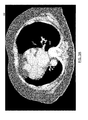
- FIGS. 3A and 3B illustrate a source image 300 and a merged image 310 , respectively, as may be employed by embodiments of the present invention as part of an improved image processing and visualization operation.
- the source image 300 is a medical image, such as a CT scan image, that includes a view of a portion of a patient's thoracic cavity.
- the source image 300 in this example includes several different anatomical elements, including the patient's soft tissue 302 (e.g., skin and muscle), the patient's lungs 304 , the patient's heart 306 , and the patient's bone 308 (e.g., spine and rib cage).
- the present brightness and contrast settings applied across the image do not allow for proper visualization of certain portions of the patient's anatomy.
- the brightness and contrast settings for the image result in an inability to discern detail within the patient's lungs 304 .
- embodiments of the present invention also function with source images that do not have brightness/contrast settings applied as part of a visualization. In such scenarios, embodiments may interact directly with raw image data to identify anatomical elements as described herein.
- An image analysis element such as the image analysis element 206 described with respect to FIG. 2 or the image analysis circuitry 110 described with respect to FIG. 1 may serve to identify regions of the image corresponding to patient anatomical elements and the particular anatomical elements displayed therein.
- Image configuration settings may be selectively applied to regions of the image corresponding to the particular anatomical elements
- FIG. 3B illustrates an example of such a merged image 310 that incorporates multiple regions having different configuration settings.
- the merged image 310 illustrates the same anatomical elements as depicted in the source image 302 .
- regions of the image corresponding to these anatomical elements are more readily visible due to the application of appropriate configuration settings (e.g., brightness and contrast) to regions of the image.
- appropriate configuration settings e.g., brightness and contrast
- fine detail on the patient's lungs 314 can be readily viewed within the merged image due to different brightness and contrast settings being applied than in the source image.
- An advantage of the merged image is readily discernable in that, while the detail of the lung region 314 is visible due to increased brightness and contrast settings in that region, detail of the bone and spine region 318 is also visible due to lower brightness and contrast settings being applied to that region.
- FIG. 4 is a flow diagram depicting an exemplary process 400 for implementing an image processing technique as described above with respect to FIGS. 2-3B in accordance with embodiments of the present invention.
- These processes may be employed by an apparatus, such as the apparatus 100 described above, to generate a merged image from a source image by identifying anatomical elements within the source image and applying configuration settings to regions within the image corresponding to those anatomical elements.
- the process describes algorithms that are implemented via hardware or software executing on hardware components of an apparatus to implement these tasks and other tasks related to implementation of improved image processing techniques. These algorithms may serve as means for implementing these tasks and other functions as described above and herein.
- a source image is received.
- the source image may be in any suitable format for viewing, such as through the use of a PACS workstation.
- the image may, for example, be a DICOM image.
- the image may be stored in an archive or electronic health records system, received directly from a medical imaging system (e.g., directly from a capturing device), over a network, as an email attachment, or via any other process or mechanism.
- the image is processed to identify one or more anatomical elements within the image.
- Processing of the image in this manner includes the use of one or more algorithms for image analysis. These algorithms may, for example, utilize computer vision techniques to determine pixel regions of the source image that correspond to particular anatomical elements, and the type of anatomical elements depicted therein. These detected anatomical elements and the regions of the source image to which they correspond may be stored for later reference.
- a first set of configuration settings are identified for a region associated with a first anatomical element.
- the first set of configuration settings may be determined, for example, by performing a table lookup on a table of configuration settings indexed by anatomical element.
- a second set of configuration settings are identified for a region associated with a second anatomical element.
- the second set of configuration settings may be determined in a similar manner as the first set of configuration settings, such as by performing a similar table lookup.
- the configuration settings applied to later images in a series may be derived from selections made for images earlier in the series.
- image regions across images in a series may be mapped to one another such that adjustments to configuration settings in a first region in a first image may be mapped to a region of a second image when viewing the second image in a series.
- the first set of configuration settings are applied to the first region of the source image and the second set of configuration settings are applied to the second region of the source image to generate a merged image.
- the merged image may have a first region that corresponds to a set of pixels visualized using the first set of configuration settings (e.g., base pixel intensity values modified by a first brightness and contrast values) and a second region that corresponds to a set of pixels visualized using the second set of configuration settings (e.g., base pixel values modified by the second brightness and contrast values).
- the merged image is stored for later retrieval, viewing, or the like.
- Some embodiments may also store information that defines the different regions of the merged image and the configuration settings used for visualization of each of the regions. Storage of this additional data may enable certain additional use cases. For example, some embodiments may provide an interface that allows a clinician to select a particular region via a user interface. Selection of that region may cause the configuration settings associated with that region to be applied across the entire image.
- each element of the flowcharts, and combinations of elements in the flowcharts may be implemented by various means, such as hardware, firmware, processor, circuitry, and/or other devices associated with execution of software including one or more computer program instructions.
- one or more of the procedures described above may be embodied by computer program instructions.
- the computer program instructions which embody the procedures described above may be stored by a memory 104 of an apparatus employing an embodiment of the present invention and executed by a processor 102 of the apparatus.
- any such computer program instructions may be loaded onto a computer or other programmable apparatus (e.g., hardware) to produce a machine, such that the resulting computer or other programmable apparatus implements the functions specified in the flowchart blocks.
- These computer program instructions may also be stored in a computer-readable memory that may direct a computer or other programmable apparatus to function in a particular manner, such that the instructions stored in the computer-readable memory produce an article of manufacture the execution of which implements the function specified in the flowchart blocks.
- the computer program instructions may also be loaded onto a computer or other programmable apparatus to cause a series of operations to be performed on the computer or other programmable apparatus to produce a computer-implemented process such that the instructions which execute on the computer or other programmable apparatus provide operations for implementing the functions specified in the flowchart blocks.
- blocks of the flowchart support combinations of means for performing the specified functions and combinations of operations. It will also be understood that one or more blocks of the flowchart, and combinations of blocks in the flowchart, can be implemented by special purpose hardware-based computer systems which perform the specified functions, or combinations of special purpose hardware and computer instructions.
- certain ones of the operations above may be modified or further amplified. Furthermore, in some embodiments, additional optional operations may be included. Modifications, additions, or amplifications to the operations above may be performed in any order and in any combination.
Landscapes
- Health & Medical Sciences (AREA)
- Engineering & Computer Science (AREA)
- Life Sciences & Earth Sciences (AREA)
- Medical Informatics (AREA)
- Physics & Mathematics (AREA)
- Nuclear Medicine, Radiotherapy & Molecular Imaging (AREA)
- Radiology & Medical Imaging (AREA)
- Public Health (AREA)
- General Health & Medical Sciences (AREA)
- Computer Vision & Pattern Recognition (AREA)
- Molecular Biology (AREA)
- Veterinary Medicine (AREA)
- Animal Behavior & Ethology (AREA)
- Surgery (AREA)
- Biophysics (AREA)
- Pathology (AREA)
- Biomedical Technology (AREA)
- Heart & Thoracic Surgery (AREA)
- Physiology (AREA)
- High Energy & Nuclear Physics (AREA)
- Optics & Photonics (AREA)
- General Physics & Mathematics (AREA)
- Theoretical Computer Science (AREA)
- Primary Health Care (AREA)
- Epidemiology (AREA)
- Image Processing (AREA)
Abstract
Description
Claims (16)
Priority Applications (1)
| Application Number | Priority Date | Filing Date | Title |
|---|---|---|---|
| US15/085,526 US10074198B2 (en) | 2016-03-30 | 2016-03-30 | Methods and apparatuses for image processing and display |
Applications Claiming Priority (1)
| Application Number | Priority Date | Filing Date | Title |
|---|---|---|---|
| US15/085,526 US10074198B2 (en) | 2016-03-30 | 2016-03-30 | Methods and apparatuses for image processing and display |
Publications (2)
| Publication Number | Publication Date |
|---|---|
| US20170287174A1 US20170287174A1 (en) | 2017-10-05 |
| US10074198B2 true US10074198B2 (en) | 2018-09-11 |
Family
ID=59961114
Family Applications (1)
| Application Number | Title | Priority Date | Filing Date |
|---|---|---|---|
| US15/085,526 Active 2036-07-09 US10074198B2 (en) | 2016-03-30 | 2016-03-30 | Methods and apparatuses for image processing and display |
Country Status (1)
| Country | Link |
|---|---|
| US (1) | US10074198B2 (en) |
Families Citing this family (2)
| Publication number | Priority date | Publication date | Assignee | Title |
|---|---|---|---|---|
| US10453237B2 (en) * | 2017-12-21 | 2019-10-22 | International Business Machines Corporation | Automatic viewport releveling |
| US11506739B2 (en) * | 2019-09-17 | 2022-11-22 | GE Precision Healthcare LLC | Systems and methods for generating localizer scan settings from calibration images |
Citations (3)
| Publication number | Priority date | Publication date | Assignee | Title |
|---|---|---|---|---|
| US20050031202A1 (en) * | 2003-02-28 | 2005-02-10 | Vittorio Accomazzi | Image region segmentation system and method |
| US20120197619A1 (en) * | 2011-01-27 | 2012-08-02 | Einav Namer Yelin | System and method for generating a patient-specific digital image-based model of an anatomical structure |
| US20130121549A1 (en) * | 2010-07-30 | 2013-05-16 | Koninklijke Philips Electronics N.V. | Organ-specific enhancement filter for robust segmentation of medical images |
-
2016
- 2016-03-30 US US15/085,526 patent/US10074198B2/en active Active
Patent Citations (3)
| Publication number | Priority date | Publication date | Assignee | Title |
|---|---|---|---|---|
| US20050031202A1 (en) * | 2003-02-28 | 2005-02-10 | Vittorio Accomazzi | Image region segmentation system and method |
| US20130121549A1 (en) * | 2010-07-30 | 2013-05-16 | Koninklijke Philips Electronics N.V. | Organ-specific enhancement filter for robust segmentation of medical images |
| US20120197619A1 (en) * | 2011-01-27 | 2012-08-02 | Einav Namer Yelin | System and method for generating a patient-specific digital image-based model of an anatomical structure |
Also Published As
| Publication number | Publication date |
|---|---|
| US20170287174A1 (en) | 2017-10-05 |
Similar Documents
| Publication | Publication Date | Title |
|---|---|---|
| US10129553B2 (en) | Dynamic digital image compression based on digital image characteristics | |
| US10127662B1 (en) | Systems and user interfaces for automated generation of matching 2D series of medical images and efficient annotation of matching 2D medical images | |
| US9704242B2 (en) | Dynamic image processing apparatus and computer-readable recording medium for providing diagnosis support | |
| US10722210B2 (en) | Method for memorable image generation for anonymized three-dimensional medical image workflows | |
| US9646393B2 (en) | Clinically driven image fusion | |
| JP7187244B2 (en) | Medical image processing device, medical image processing system and medical image processing program | |
| JP6448356B2 (en) | Image processing apparatus, image processing method, image processing system, and program | |
| US10185805B2 (en) | Medical image processing apparatus and method | |
| CN104637024A (en) | Medical image processing device and medical image processing method | |
| CN105144241A (en) | Image quality index and/or imaging parameter recommendation based thereon | |
| CN107633478B (en) | Image processing apparatus, image processing method, and computer readable medium | |
| EP3273409A1 (en) | Image processing apparatus and image processing method | |
| JP2017534316A (en) | Image report annotation identification | |
| US20160292844A1 (en) | Medical image registration apparatus, medical image registration method, and medical image registration program | |
| JP6995535B2 (en) | Image processing equipment, image processing methods and programs | |
| US20160225181A1 (en) | Method and apparatus for displaying medical image | |
| CN111063424A (en) | Intervertebral disc data processing method and device, electronic equipment and storage medium | |
| WO2019146358A1 (en) | Learning system, method, and program | |
| US9933849B2 (en) | Method and computing device for window leveling based upon a gaze location | |
| WO2024102765A1 (en) | Registration based medical image analysis | |
| US10074198B2 (en) | Methods and apparatuses for image processing and display | |
| JP6564075B2 (en) | Selection of transfer function for displaying medical images | |
| US12374444B2 (en) | Creating a synthetic medical image | |
| JP2021182403A (en) | Converter, method for conversion, and program | |
| JP2018033698A (en) | Image display device, image display method, and program |
Legal Events
| Date | Code | Title | Description |
|---|---|---|---|
| AS | Assignment |
Owner name: MCKESSON CORPORATION, CALIFORNIA Free format text: ASSIGNMENT OF ASSIGNORS INTEREST;ASSIGNOR:MUSLIH, FAISAL;REEL/FRAME:038141/0648 Effective date: 20160330 |
|
| AS | Assignment |
Owner name: MCKESSON FINANCIAL HOLDINGS, BERMUDA Free format text: ASSIGNMENT OF ASSIGNORS INTEREST;ASSIGNOR:MCKESSON CORPORATION;REEL/FRAME:039887/0935 Effective date: 20160830 |
|
| AS | Assignment |
Owner name: MCKESSON FINANCIAL HOLDINGS UNLIMITED COMPANY, BERMUDA Free format text: CHANGE OF NAME;ASSIGNOR:MCKESSON FINANCIAL HOLDINGS;REEL/FRAME:041329/0879 Effective date: 20161130 Owner name: MCKESSON FINANCIAL HOLDINGS UNLIMITED COMPANY, BER Free format text: CHANGE OF NAME;ASSIGNOR:MCKESSON FINANCIAL HOLDINGS;REEL/FRAME:041329/0879 Effective date: 20161130 |
|
| AS | Assignment |
Owner name: MCKESSON CORPORATION, CALIFORNIA Free format text: ASSIGNMENT OF ASSIGNORS INTEREST;ASSIGNOR:MCKESSON FINANCIAL HOLDINGS UNLIMITED COMPANY;REEL/FRAME:041355/0408 Effective date: 20161219 |
|
| AS | Assignment |
Owner name: BANK OF AMERICA, N.A., AS COLLATERAL AGENT, NORTH CAROLINA Free format text: SECURITY AGREEMENT;ASSIGNORS:CHANGE HEALTHCARE HOLDINGS, LLC;CHANGE HEALTHCARE, INC.;CHANGE HEALTHCARE HOLDINGS, INC.;AND OTHERS;REEL/FRAME:041858/0482 Effective date: 20170301 Owner name: BANK OF AMERICA, N.A., AS COLLATERAL AGENT, NORTH Free format text: SECURITY AGREEMENT;ASSIGNORS:CHANGE HEALTHCARE HOLDINGS, LLC;CHANGE HEALTHCARE, INC.;CHANGE HEALTHCARE HOLDINGS, INC.;AND OTHERS;REEL/FRAME:041858/0482 Effective date: 20170301 |
|
| AS | Assignment |
Owner name: PF2 IP LLC, CALIFORNIA Free format text: ASSIGNMENT OF ASSIGNORS INTEREST;ASSIGNOR:MCKESSON CORPORATION;REEL/FRAME:041938/0501 Effective date: 20170301 |
|
| AS | Assignment |
Owner name: CHANGE HEALTHCARE LLC, CALIFORNIA Free format text: ASSIGNMENT OF ASSIGNORS INTEREST;ASSIGNOR:PF2 IP LLC;REEL/FRAME:041966/0356 Effective date: 20170301 |
|
| AS | Assignment |
Owner name: CHANGE HEALTHCARE LLC, GEORGIA Free format text: CHANGE OF ADDRESS;ASSIGNOR:CHANGE HEALTHCARE LLC;REEL/FRAME:042082/0061 Effective date: 20170323 |
|
| AS | Assignment |
Owner name: CHANGE HEALTHCARE HOLDINGS, LLC, TENNESSEE Free format text: ASSIGNMENT OF ASSIGNORS INTEREST;ASSIGNOR:CHANGE HEALTHCARE LLC;REEL/FRAME:046449/0899 Effective date: 20180414 |
|
| STCF | Information on status: patent grant |
Free format text: PATENTED CASE |
|
| MAFP | Maintenance fee payment |
Free format text: PAYMENT OF MAINTENANCE FEE, 4TH YEAR, LARGE ENTITY (ORIGINAL EVENT CODE: M1551); ENTITY STATUS OF PATENT OWNER: LARGE ENTITY Year of fee payment: 4 |
|
| AS | Assignment |
Owner name: CHANGE HEALTHCARE HOLDINGS, LLC, MINNESOTA Free format text: RELEASE BY SECURED PARTY;ASSIGNOR:BANK OF AMERICA, N.A.;REEL/FRAME:061620/0054 Effective date: 20221003 Owner name: CHANGE HEALTHCARE TECHNOLOGIES, LLC (FORMERLY KNOWN AS MCKESSON TECHNOLOGIES LLC), MINNESOTA Free format text: RELEASE BY SECURED PARTY;ASSIGNOR:BANK OF AMERICA, N.A.;REEL/FRAME:061620/0054 Effective date: 20221003 Owner name: CHANGE HEALTHCARE HOLDINGS, INC., MINNESOTA Free format text: RELEASE BY SECURED PARTY;ASSIGNOR:BANK OF AMERICA, N.A.;REEL/FRAME:061620/0054 Effective date: 20221003 Owner name: CHANGE HEALTHCARE OPERATIONS, LLC, MINNESOTA Free format text: RELEASE BY SECURED PARTY;ASSIGNOR:BANK OF AMERICA, N.A.;REEL/FRAME:061620/0054 Effective date: 20221003 Owner name: CHANGE HEALTHCARE PERFORMANCE, INC. (FORMERLY KNOWN AS CHANGE HEALTHCARE, INC.), MINNESOTA Free format text: RELEASE BY SECURED PARTY;ASSIGNOR:BANK OF AMERICA, N.A.;REEL/FRAME:061620/0054 Effective date: 20221003 Owner name: CHANGE HEALTHCARE SOLUTIONS, LLC, MINNESOTA Free format text: RELEASE BY SECURED PARTY;ASSIGNOR:BANK OF AMERICA, N.A.;REEL/FRAME:061620/0054 Effective date: 20221003 Owner name: CHANGE HEALTHCARE RESOURCES, LLC (FORMERLY KNOWN AS ALTEGRA HEALTH OPERATING COMPANY LLC), MINNESOTA Free format text: RELEASE BY SECURED PARTY;ASSIGNOR:BANK OF AMERICA, N.A.;REEL/FRAME:061620/0054 Effective date: 20221003 |
|
| MAFP | Maintenance fee payment |
Free format text: PAYMENT OF MAINTENANCE FEE, 8TH YEAR, LARGE ENTITY (ORIGINAL EVENT CODE: M1552); ENTITY STATUS OF PATENT OWNER: LARGE ENTITY Year of fee payment: 8 |