US10073319B2 - QAM vector signal generation by external modulator - Google Patents
QAM vector signal generation by external modulator Download PDFInfo
- Publication number
- US10073319B2 US10073319B2 US15/146,787 US201615146787A US10073319B2 US 10073319 B2 US10073319 B2 US 10073319B2 US 201615146787 A US201615146787 A US 201615146787A US 10073319 B2 US10073319 B2 US 10073319B2
- Authority
- US
- United States
- Prior art keywords
- optical
- amplitude
- signal
- component signals
- electro
- Prior art date
- Legal status (The legal status is an assumption and is not a legal conclusion. Google has not performed a legal analysis and makes no representation as to the accuracy of the status listed.)
- Expired - Fee Related
Links
- 230000007274 generation of a signal involved in cell-cell signaling Effects 0.000 title description 24
- 230000003287 optical effect Effects 0.000 claims description 138
- 238000000034 method Methods 0.000 claims description 55
- 230000010287 polarization Effects 0.000 claims description 41
- 230000005540 biological transmission Effects 0.000 claims description 37
- 238000001514 detection method Methods 0.000 claims description 26
- 238000006243 chemical reaction Methods 0.000 claims description 25
- 238000004891 communication Methods 0.000 claims description 18
- 230000006870 function Effects 0.000 claims description 11
- 230000009977 dual effect Effects 0.000 claims description 6
- 230000000116 mitigating effect Effects 0.000 claims 3
- 238000001228 spectrum Methods 0.000 description 19
- 238000012545 processing Methods 0.000 description 11
- 239000000835 fiber Substances 0.000 description 10
- 238000004590 computer program Methods 0.000 description 9
- 238000003780 insertion Methods 0.000 description 7
- 230000037431 insertion Effects 0.000 description 7
- 239000013307 optical fiber Substances 0.000 description 6
- 238000005070 sampling Methods 0.000 description 6
- 230000035945 sensitivity Effects 0.000 description 6
- 238000004422 calculation algorithm Methods 0.000 description 4
- 230000001427 coherent effect Effects 0.000 description 4
- 239000006185 dispersion Substances 0.000 description 4
- 230000003595 spectral effect Effects 0.000 description 4
- 238000012360 testing method Methods 0.000 description 4
- 230000008901 benefit Effects 0.000 description 3
- 238000002474 experimental method Methods 0.000 description 3
- 238000013507 mapping Methods 0.000 description 3
- 230000008569 process Effects 0.000 description 3
- 230000001629 suppression Effects 0.000 description 3
- 238000010420 art technique Methods 0.000 description 2
- 238000010009 beating Methods 0.000 description 2
- 239000000969 carrier Substances 0.000 description 2
- 238000012937 correction Methods 0.000 description 2
- 238000005516 engineering process Methods 0.000 description 2
- 238000000605 extraction Methods 0.000 description 2
- 238000005259 measurement Methods 0.000 description 2
- 239000000203 mixture Substances 0.000 description 2
- 230000000644 propagated effect Effects 0.000 description 2
- 238000011160 research Methods 0.000 description 2
- 238000013515 script Methods 0.000 description 2
- 239000004065 semiconductor Substances 0.000 description 2
- 230000003044 adaptive effect Effects 0.000 description 1
- 230000033590 base-excision repair Effects 0.000 description 1
- 230000015556 catabolic process Effects 0.000 description 1
- 230000008859 change Effects 0.000 description 1
- 239000013256 coordination polymer Substances 0.000 description 1
- 238000006731 degradation reaction Methods 0.000 description 1
- 238000010586 diagram Methods 0.000 description 1
- -1 e.g. Substances 0.000 description 1
- 230000000694 effects Effects 0.000 description 1
- 238000001914 filtration Methods 0.000 description 1
- 239000003365 glass fiber Substances 0.000 description 1
- 238000012986 modification Methods 0.000 description 1
- 230000004048 modification Effects 0.000 description 1
- 239000013308 plastic optical fiber Substances 0.000 description 1
- 230000008054 signal transmission Effects 0.000 description 1
- 239000000758 substrate Substances 0.000 description 1
- 238000012546 transfer Methods 0.000 description 1
Images


Classifications
-
- G—PHYSICS
- G02—OPTICS
- G02F—OPTICAL DEVICES OR ARRANGEMENTS FOR THE CONTROL OF LIGHT BY MODIFICATION OF THE OPTICAL PROPERTIES OF THE MEDIA OF THE ELEMENTS INVOLVED THEREIN; NON-LINEAR OPTICS; FREQUENCY-CHANGING OF LIGHT; OPTICAL LOGIC ELEMENTS; OPTICAL ANALOGUE/DIGITAL CONVERTERS
- G02F1/00—Devices or arrangements for the control of the intensity, colour, phase, polarisation or direction of light arriving from an independent light source, e.g. switching, gating or modulating; Non-linear optics
- G02F1/01—Devices or arrangements for the control of the intensity, colour, phase, polarisation or direction of light arriving from an independent light source, e.g. switching, gating or modulating; Non-linear optics for the control of the intensity, phase, polarisation or colour
- G02F1/21—Devices or arrangements for the control of the intensity, colour, phase, polarisation or direction of light arriving from an independent light source, e.g. switching, gating or modulating; Non-linear optics for the control of the intensity, phase, polarisation or colour by interference
- G02F1/225—Devices or arrangements for the control of the intensity, colour, phase, polarisation or direction of light arriving from an independent light source, e.g. switching, gating or modulating; Non-linear optics for the control of the intensity, phase, polarisation or colour by interference in an optical waveguide structure
- G02F1/2255—Devices or arrangements for the control of the intensity, colour, phase, polarisation or direction of light arriving from an independent light source, e.g. switching, gating or modulating; Non-linear optics for the control of the intensity, phase, polarisation or colour by interference in an optical waveguide structure controlled by a high-frequency electromagnetic component in an electric waveguide structure
-
- H—ELECTRICITY
- H04—ELECTRIC COMMUNICATION TECHNIQUE
- H04B—TRANSMISSION
- H04B10/00—Transmission systems employing electromagnetic waves other than radio-waves, e.g. infrared, visible or ultraviolet light, or employing corpuscular radiation, e.g. quantum communication
- H04B10/50—Transmitters
- H04B10/516—Details of coding or modulation
- H04B10/54—Intensity modulation
- H04B10/541—Digital intensity or amplitude modulation
-
- G—PHYSICS
- G02—OPTICS
- G02F—OPTICAL DEVICES OR ARRANGEMENTS FOR THE CONTROL OF LIGHT BY MODIFICATION OF THE OPTICAL PROPERTIES OF THE MEDIA OF THE ELEMENTS INVOLVED THEREIN; NON-LINEAR OPTICS; FREQUENCY-CHANGING OF LIGHT; OPTICAL LOGIC ELEMENTS; OPTICAL ANALOGUE/DIGITAL CONVERTERS
- G02F1/00—Devices or arrangements for the control of the intensity, colour, phase, polarisation or direction of light arriving from an independent light source, e.g. switching, gating or modulating; Non-linear optics
- G02F1/01—Devices or arrangements for the control of the intensity, colour, phase, polarisation or direction of light arriving from an independent light source, e.g. switching, gating or modulating; Non-linear optics for the control of the intensity, phase, polarisation or colour
- G02F1/21—Devices or arrangements for the control of the intensity, colour, phase, polarisation or direction of light arriving from an independent light source, e.g. switching, gating or modulating; Non-linear optics for the control of the intensity, phase, polarisation or colour by interference
- G02F1/212—Mach-Zehnder type
-
- G02F2001/212—
Definitions
- This patent document relates to digital communication, and, in one aspect, optical communication systems.
- the present document discloses, among other things, techniques for generating modulated optical signals in which photonic frequency multiplexing is achieved by using a single external modulator to process a QAM (Quadrature Amplitude Modulation) vector signal in which high order QAM constellations are used.
- QAM Quadrature Amplitude Modulation
- a method of optical communication implemented at a transmitter in an optical communication network includes modulating information bits to be transferred using a multi-amplitude amplitude modulation scheme to produce modulated electrical in-phase and quadrature component signals, precoding the in-phase and quadrature component signals to mitigate distortions in a subsequence electrical to optical conversion stage, wherein the precoding modifies amplitudes of the component signals and phases of the component signals, and converting the precoded component signals using a single electro-optical modulator into a radio frequency (RF) optical signal comprising two component optical signals at two different subcarrier frequencies and with a suppressed carrier signal.
- RF radio frequency
- an optical transmission apparatus includes a modulation circuit that modulates information bits to be transferred using a multi-amplitude amplitude modulation scheme to produce modulated electrical in-phase and quadrature component signals, a precoder that precodes the in-phase and quadrature component signals to mitigate distortions in a subsequence electrical to optical conversion stage, wherein the precoding modifies amplitudes of the component signals and phases of the component signals, and an electro-optical modulation stage that converts the precoded component signals using a single electro-optical modulator into a radio frequency (RF) optical signal comprising two component optical signals at two different subcarrier frequencies and with a suppressed carrier signal.
- RF radio frequency
- FIG. 1 shows an example optical communication network.
- FIG. 2 shows an example optical signal transmission method
- FIG. 3 shows an example optical communication receiver apparatus.
- FIGS. 4A-4B show an example of ( 4 A) principle of photonic vector signal generation at RF bands, and ( 4 B) vector-modulated precoded RF signal generation (MZM: Mach-Zehnder modulator, PD: photodiode).
- MZM Mach-Zehnder modulator
- PD photodiode
- FIGS. 5A-5B show an example of transmitter spectra ( 5 A) before and ( 5 B) after up-conversion.
- FIG. 6 shows original and precoded constellations for QPSK/8QAM/16QAM vector signals at the transmitter.
- FIGS. 7A-7C show an experimental setup.
- FIG. 7A shows output electrical waveform (50 ps/div) of AWG.
- FIG. 7B shows output optical spectra (0.02-nm resolution) of MZM.
- FIG. 7C shows an experimental arrangement that includes ECL: external cavity laser, MZM: Mach-Zehnder modulator, AWG: arbitrary waveform generator, EA: electrical amplifier, EDFA: erbium-doped fiber amplifier, PD: photodiode, OSC: oscilloscope.
- FIG. 8 shows received RF spectra and constellations for QPSK/8QAM/16QAM vector signals at the receiver.
- FIG. 9 shows measured BER versus the launched optical power into PD for 1-Gbaud QPSK/8QAM/16QAM vector signals.
- FIGS. 10A-10E show an experimental setup. Transmitter QPSK constellations ( FIG. 10A ) before and ( FIG. 10B ) after phase precoding are shown.
- FIG. 10C shows 6-GHz precoded vector signal spectrum.
- FIG. 10D shows output electrical waveform (25 ps/div) of AWG.
- FIG. 10E shows an experimental setup.
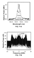
- FIGS. 11A-11B show ( FIG. 11A ) output optical spectrum (0.02-nm resolution) of the MZM, and ( FIG. 11B ) received 12-GHz vector signal spectrum.
- FIG. 12A shows measured BER versus the launched optical power into PD. Received ( FIG. 12B ) X- and ( FIG. 12C ) Y-polarization QPSK constellations are shown.
- FIG. 13 shows the principle of an example of 16QAM vector signal generation, using OCS intensity modulation and direct detection.
- FIGS. 14A-14E show an experimental setup. Transmitter constellations after ( FIG. 14A ) 16QAM mapping, ( FIG. 14B ) amplitude precoding, and ( FIG. 14C ) phase precoding.
- FIG. 14D shows 12-GHz precoded vector signal spectrum.
- FIG. 14E shows the experimental setup.
- FIGS. 16A-16D show BER versus the launched optical power into PD.
- optical communication data is transmitted over optical carriers, e.g., glass or plastic optical fibers by modulating using a variety of different techniques. Some techniques implement data modulation in the electrical domain, e.g., by processing electronic signals. Alternatively or in addition, data modulation can also be achieved in the optical domain, e.g., using photonic signal processing.
- FIG. 1 depicts an optical communication system 700 in which the presently disclosed technology can be embodied.
- One or more optical transmitters 702 are communicatively coupled via an optical network 704 with one or more optical receivers 706 .
- the optical network 704 may comprise optical fibers that extend in length from several hundred feet (e.g., last mile drop) to several thousands of kilometers (long haul networks).
- the transmitted optical signals may go through intermediate optical equipment such as amplifiers, repeaters, switch, etc., which are not shown in FIG. 1 for clarity.
- photonic QAM vector signal generation at microwave/millimeter-wave (mm-wave) bands is enabled by a single Mach-Zehnder modulator (MZM) or a phase modulator and a phase-precoding technique, which can realize adaptive photonic frequency multiplication, such as doubling ( ⁇ 2), quadrupling ( ⁇ 4), sextupling ( ⁇ 6) and octupling ( ⁇ 8), of the precoded microwave vector signal used for the drive of the single MZM or optical phase modulator.
- MZM Mach-Zehnder modulator
- phase modulator phase modulator
- phase-precoding technique which can realize adaptive photonic frequency multiplication, such as doubling ( ⁇ 2), quadrupling ( ⁇ 4), sextupling ( ⁇ 6) and octupling ( ⁇ 8), of the precoded microwave vector signal used for the drive of the single MZM or optical phase modulator.
- two optical carriers are modulated with two independent baseband data streams I and Q.
- the two optical signals can either be of the same source divided into two streams, or two different lasers, and the data modulation can be either direct current modulation of the lasers such as distributed feedback lasers (DFB) or external modulation using electro-optical modulators like Mach-Zehnder modulators (MZM).
- DFB distributed feedback lasers
- MZM Mach-Zehnder modulators
- headers are used for clarity of explanation are not intended to limit scope of the techniques to the header-captioned category only.
- RoF radio-over-fiber
- I in-phase
- Q quadrature
- the technique of external intensity modulation makes use of the beating of the sidebands generated by external intensity modulator driven by a radio-frequency (RF) signal, and can provide RoF systems with very stable RF carrier, the frequency of which only depends on the driving RF signal. Moreover, external intensity modulation combined with photonic frequency multiplication can realize high-frequency RF signal generation with the reduced bandwidth requirement for both optical and electrical components at the transmitter end.
- One prior art implementation used photonic vector signal generation at RF bands employing dual-parallel Mach-Zehnder modulator (MZM)-based photonic frequency quadrupling and precoding techniques. Relative to one intensity modulator, a dual-parallel MZM is more expensive and also more complicated to control.
- the generated vector signal is constant-amplitude quadrature-phase-shift-keying (QPSK) modulated, and no higher-order multi-amplitude modulation, such as 8-ary quadrature-amplitude-modulation (8QAM) and 16-ary quadrature-amplitude-modulation (16QAM), is considered in that work.
- QPSK quadrature-phase-shift-keying
- the MZM used for OCS modulation is driven by a 6-GHz precoded RF signal carrying 1-Gbaud QPSK/8QAM/16QAM transmitter data.
- some embodiments include the generation and reception of higher-order 8QAM and 16QAM vector signal by one external modulator at RF bands.
- FIG. 4A shows the schematic diagram of example photonic multi-amplitude (e.g., constellation symbols having different amplitude levels, e.g., 8 or higher) QAM vector signal generation at RF bands, using OCS modulation enabled by a single MZM.
- the continuous wave (CW) output, at frequency f c from a laser, is modulated by an RF carrier at frequency f s , which carries a multi-amplitude QAM data and drives the MZM.
- E RF ( t ) K 2 ( t )sin [2 ⁇ f s t + ⁇ ( t )].
- K 1 is constant and denotes the amplitude of the CW output at frequency f c .
- K 2 and ⁇ denote the amplitude and phase of the driving RF signal at frequency f s , respectively.
- K 2 is invariant with time when the transmitter data adopts constant-amplitude vector modulation, such as QPSK, and has several different values when the transmitter data adopts multi-amplitude vector modulation, such as 8QAM and 16QAM.
- K data and ⁇ data denote the amplitude and phase of the original transmitter data, respectively. Therefore, the amplitude and phase of the driving RF signal needs to be precoded at the transmitter end.
- the obtained values of K 2 and ⁇ by resolving Eq. (5) are just the precoded amplitude and phase which can be assigned to the driving RF signal.
- 4B shows the generation procedure of driving precoded RF signal at frequency f s carrying multi-amplitude QAM data, which can be implemented by MATLAB programming.
- PRBS pseudo random binary sequence
- the transmitter data adopts constant-amplitude vector modulation, such as QPSK, only phase precoding is needed.
- multi-amplitude vector modulation such as 8QAM and 16QAM, both phase and amplitude precoding are required.
- a 6-GHz precoded RF signal carrying 1-Gbaud vector-modulated transmitter data is generated by MATLAB programming (for testing) or could be actual user data during operation, and then uploaded into an arbitrary waveform generator (AWG) with 64-GSa/s sampling rate to drive the MZM biased at its minimum transmission point.
- the transmitter data can be QPSK, 8QAM or 16QAM modulated.
- the phase of the 6-GHz precoded RF signal is 1 ⁇ 2 of that of the regular QPSK/8QAM/16QAM symbol, while its amplitude depends on the amplitude of the regular QPSK/8QAM/16QAM symbol and the ratio of V drive to V ⁇ .
- FIG. 6 the calculated original constellations as well as the calculated constellations after only phase precoding, after only amplitude precoding and after both amplitude and phase precoding for the 1-Gbaud QPSK/8QAM/16QAM signals, respectively.
- the order of amplitude precoding and phase precoding can be exchanged, and the ratio of V drive to V ⁇ is set at 3 for the MATLAB-based amplitude precoding.
- FIGS. 5A and 5B show the transmitter spectra before and after 6-GHz up-conversion for the QPSK cases, and both the 8QAM and 16QAM cases have quite similar transmitter spectra, which are not shown in this document.
- FIGS. 7A-7C show the experimental setup for multi-amplitude QAM vector signal generation at 12 GHz adopting MZM-based OCS modulation and precoding techniques.
- the CW output from an external cavity laser (ECL) is modulated by the aforementioned 6-GHz precoded RF signal via a MZM.
- the 6-GHz precoded RF signal carries 2 15 QAM symbols and is boosted by an electrical amplifier (EA) to ⁇ 20 dBm to drive the MZM.
- EA electrical amplifier
- the MZM has a 3-dB bandwidth of ⁇ 36 GHz, 2.8-V half-wave voltage (V ⁇ ) at 1 GHz and 5-dB insertion loss.
- the MZM is biased at its minimum transmission point to realize OCS modulation.
- FIG. 7A gives the output electrical waveform (50 ps/div) of the AWG
- FIG. 7B gives the output optical spectrum (0.02-nm resolution) of the MZM, showing that two first-order optical subcarriers are generated with 12-GHz frequency spacing after OCS modulation. These two generated first-order optical subcarriers have the same amplitude but carry opposite phase information.
- the cases of 1-Gbaud 8QAM and 16QAM signals have quite similar electrical waveform and optical spectrum, which are not shown in this document.
- the 12-GHz QAM modulated optical RF signal is converted by a PD into a 12-GHz QAM modulated electrical RF signal, which is then captured by a digital oscilloscope (OSC) with 40-GSa/s sampling rate and 16-GHz electrical bandwidth.
- the QAM modulated transmitter data can be recovered from the 12-GHz electrical RF signal after offline digital signal processing (DSP), which includes IF down conversion, constant modulus algorithm (CMA) equalization for QPSK modulation or cascaded multi-modulus algorithm (CMMA) equalization for 8QAM/16QAM modulation, frequency offset estimation (FOE), and carrier phase estimation (CPE).
- DSP digital signal processing
- CMA constant modulus algorithm
- CMMA cascaded multi-modulus algorithm
- 8QAM/16QAM modulation frequency offset estimation
- CPE carrier phase estimation
- FIG. 8 gives the received 12-GHz RF spectra and constellations for the 1-Gbaud QPSK/8QAM/16QAM vector signals, respectively.
- the launched optical power into the PD is ⁇ 10, ⁇ 8, and ⁇ 2 dBm for the 1-Gbaud QPSK/8QAM/16QAM vector signals, respectively.
- the BERs are all zero for these three cases.
- the constellations from left to right in Table II correspond to those before clock extraction, after clock extraction, after CMA/CMMA equalization, after FOE and after CPE, respectively.
- FIG. 9 shows the measured bit-error-ratio (BER) performance versus the launched optical power into PD for the 1-Gbaud QPSK/8QAM/16QAM vector signals, respectively.
- the BER can reach the hard-decision forward-error-correction (HD-FEC) threshold of 3.8 ⁇ 10 ⁇ 3 for all three cases.
- HD-FEC hard-decision forward-error-correction
- the OSNR requirement for 8QAM and 16QAM is 5-dB and 11-dB higher than that for QPSK, respectively. It is because higher-order modulation formats require higher receiver sensitivity.
- the phase of the precoded RF signal is 1 ⁇ 2 of that of the regular QPSK/8QAM/16QAM symbol, while its amplitude depends on the amplitude of the regular QPSK/8QAM/16QAM symbol and the ratio of driving voltage to half-wave voltage of the MZM.
- IM-DD intensity modulation and direction detection
- DSP digital signal processing
- Some prior art techniques use a relatively simple method to generate PDM-16QAM vector signal based on directly modulated laser and direct detection.
- this method is polarization sensitive, and a polarization tracking system is needed at the receiver to realize polarization de-multiplexing.
- the inventors have previously disclosed QPSK and 8QAM modulated vector signal generation at W-band based on IM-DD enabled photonic frequency octupling and precoding techniques.
- those embodiments adopt only one optical polarization.
- This document discloses polarization-division-multiplexing quadrature-phase-shift-keying (PDM-QPSK) modulated vector signal generation adopting MZM-based optical-carrier-suppression (OCS) intensity modulation and direct detection.
- the MZM is driven by a 6-GHz precoded vector signal carrying 2-Gbaud QPSK transmitter data, and biased at its minimum transmission point to realize OCS modulation.
- the phase of the 6-GHz precoded vector signal is 1 ⁇ 2 of that of the regular QPSK symbol.
- PBS polarization beam splitter
- the bit-error rate (BER) for the 2-Gbaud PDM-QPSK modulated vector signal can reach the hard-decision forward-error-correction (HD-FEC) threshold of 3.8 ⁇ 10 ⁇ 3 after 80-km single-mode fiber-28 (SMF-28) transmission in the presence of optical dispersion compensation, and 80-km SMF-28 transmission causes no power penalty.
- HD-FEC hard-decision forward-error-correction
- FIGS. 10A-10E show the experimental setup for PDM-QPSK modulated vector signal generation adopting MZM-based OCS intensity modulation and direct detection.
- a precoded vector signal at 6 GHz, carrying 2- or 4-Gbaud QPSK data is generated by MATLAB programming. That is, a pseudo random binary sequence (PRBS), with a length of 2 10 , is first QPSK mapped, then phase-precoded, and finally up-converted into 6-GHz RF band by simultaneous cosine and sine functions.
- PRBS pseudo random binary sequence
- FIGS. 10A and 10B show the calculated constellations after QPSK mapping and phase precoding, respectively. We can see that the precoded phase is 1 ⁇ 2 of that of the regular QPSK symbol.
- FIG. 10C gives the calculated 6-GHz precoded vector signal spectrum after up-conversion. Then, the generated 6-GHz precoded vector signal by MATLAB programming is uploaded into an arbitrary waveform generator (AWG) with 64-GSa/s sampling rate and 13-GHz electrical bandwidth to implement digital-to-analog conversion (DAC).
- FIG. 10D gives the output electrical waveform (25 ps/div) of the AWG. Note that FIGS. 10A-10D are all calculated or measured at 2 Gbaud.
- the 6-GHz precoded vector signal is used to modulate the continuous-wave (CW) output from an external cavity laser (ECL) via a MZM.
- the MZM has a 3-dB bandwidth of ⁇ 36 GHz, 2.8-V half-wave voltage (V T ) at 1 GHz and 5-dB insertion loss.
- the MZM is biased at its minimum transmission point to realize OCS modulation.
- FIG. 11A gives the output optical spectrum (0.02-nm resolution) of the MZM at 2 Gbaud. We can see that two first-order optical subcarriers are generated with 12-GHz frequency spacing after OCS modulation.
- Polarization multiplexing is further implemented by a polarization multiplexer, which includes a polarization-maintaining optical coupler (PM-OC) to split the signal into two components, a variable optical delay line to provide a delay of 90 symbols, a variable optical attenuator (VOA) to balance the power of the two components and a polarization beam combiner (PBC) to recombine the two components.
- PM-OC polarization-maintaining optical coupler
- VOA variable optical attenuator
- PBC polarization beam combiner
- the optical signal with 0-dBm launched power is first sent into a span of dispersion-compensating fiber (DCF) in cascade with an erbium-doped fiber amplifier (EDFA), and then a span of 80-km SMF-28 in cascade with an EDFA.
- the DCF with 6-dB insertion loss, is used to implement optical full-dispersion compensation for 80-km SMF-28.
- the SMF-28 has 18-dB average loss and 17-ps/km/nm CD at 1550 nm.
- a VOA is added to adjust the optical power for BER measurement.
- a PBS is first used to implement optical polarization diversity of the received optical signal. Then, the obtained X- and Y-polarization optical components are up-converted by two parallel photo detectors (PDs) into two 12-GHz electrical RF signals, which are simultaneously captured by two analog-to-digital-conversion (ADC) channels of a four-channel digital oscilloscope (OSC).
- the PD has 15-GHz optical bandwidth.
- Each ADC channel of the digital OSC has 40-GSa/s sampling rate and 16-GHz electrical bandwidth.
- the doubling of the driving frequency of the MZM also leads to the doubling of the driving phase of the MZM at the same time.
- the two 12-GHz electrical RF signals directly attained after PD conversion can display regular QPSK modulation.
- the polarization of the light in front of the PBS in FIG. 10E is arbitrary due to the fiber transmission.
- the X- or Y-polarization component at the output port of the PBS contains a mix of the data which is simultaneously encoded on the X- and Y-polarization at the transmitter.
- the transmitter QPSK data can be recovered from the two 12-GHz electrical RF signals after offline digital signal processing (DSP), which includes intermediate-frequency (IF) down conversion, constant modulus algorithm (CMA) equalization, frequency offset estimation, carrier phase estimation, differential decoding and BER counting.
- DSP digital signal processing
- IF intermediate-frequency
- CMA constant modulus algorithm
- FIG. 12A shows the measured BER versus the launched optical power into PD for four different cases, i.e., 2-Gbaud BTB SP-QPSK, 2-Gbaud BTB PDM-QPSK, 2-Gbaud PDM-QPSK after 80-km SMF-28 transmission and 4-Gbaud BTB PDM-QPSK, respectively.
- 80-km SMF-28 transmission causes no power penalty for the 2-Gbaud PDM-QPSK case.
- the 2-Gbaud PDM-QPSK case has a ⁇ 3-dB power penalty compared to the 2-Gbaud BTB SP-QPSK case, which is mainly because of the adoption of the additional optical polarization diversity for the 2-Gbaud PDM-QPSK case.
- FIGS. 12B and 12C show the recovered error-free X- and Y-polarization QPSK constellations for the 2-Gbaud PDM-QPSK case after 80-km SMF-28 transmission.
- the corresponding launched optical power into PD is ⁇ 12 dBm.
- the MZM is driven by a 6-GHz precoded vector signal carrying 2-Gbaud QPSK transmitter data, and biased at its minimum transmission point to realize OCS modulation.
- the phase of the 6-GHz precoded vector signal is 1 ⁇ 2 of that of the regular QPSK symbol.
- the BER for the 2-Gbaud PDM-QPSK modulated vector signal can reach the HD-FEC threshold of 3.8 ⁇ 10 ⁇ 3 after 80-km SMF-28 transmission in the presence of optical dispersion compensation.
- IM-DD intensity modulation and direction detection
- DSP digital signal processing
- the optical polarization multiplexing technique is a practical solution for the future spectrally-efficient high-speed optical transmission to double the capacity of a fiber link.
- the commonly used method for PDM-16QAM vector signal generation is based on I/Q modulation and coherent detection, which is very complicated and expensive for short reach optical fiber systems.
- Some prior art techniques use a relatively simple method to generate PDM-16QAM vector signal based on directly modulated laser and direct detection. However, this method is polarization sensitive, and a polarization tracking system is needed at the receiver to realize polarization de-multiplexing.
- Up to 64-Gb/s PDM-16QAM vector signal is generated and detected after 2-km single-mode fiber-28 (SMF-28) or 20-km large-effective-area fiber (LEAF) transmission with a BER less than the HD-FEC threshold of 3.8 ⁇ 10 ⁇ 3 .
- SMF-28 2-km single-mode fiber-28
- LEAF 20-km large-effective-area fiber
- FIG. 13 shows an example of 16QAM vector signal generation, using OCS intensity modulation and direct detection.
- the continuous wave (CW) output, at frequency f c , from a laser, is modulated by an RF carrier at frequency f s , which carries a precoded 16QAM data and drives the MZM.
- E RF ( t ) K 2 ( t )sin [2 ⁇ f s t + ⁇ ( t )].
- K 1 is constant and denotes the amplitude of the CW output at frequency f c .
- K 2 and ⁇ denote the amplitude and phase of the driving RF signal at frequency f s , respectively.
- K 2 has three different values corresponding to the three different amplitudes of the precoded 16QAM data.
- J n is the Bessel function of the first kind and order n.
- ⁇ is equal to ⁇ V drive K 2 (t)/V ⁇
- V drive and V ⁇ denote driving voltage and half-wave voltage of the MZM, respectively.
- FIGS. 14A-14E show the experimental setup for up to 64-Gb/s PDM-16QAM vector signal generation and detection adopting MZM-based OCS intensity modulation and direct detection.
- a precoded vector signal at 12 GHz carrying 8-Gbaud 16QAM data
- MATLAB programming that is, a PRBS, with a length of 2 11 , is first 16QAM mapped, then both amplitude- and phase-precoded, and finally up-converted into 12-GHz RF band by simultaneous cosine and sine functions.
- FIGS. 14A, 14B and 14C show the calculated constellations after 16QAM mapping, amplitude precoding and phase precoding, respectively.
- FIG. 14B is jointly determined by the amplitude of FIG. 14A and the ratio of driving voltage to half-wave voltage of the adopted MZM in our experiment, while the phase of FIG. 14C is precoded as 1 ⁇ 2 of that of FIG. 14A to overcome the phase doubling effect accompanying frequency doubling after square-law PD detection.
- FIG. 14D gives the calculated 12-GHz precoded vector signal spectrum after up-conversion. Then, the generated 12-GHz precoded vector signal by MATLAB programming is uploaded into an arbitrary waveform generator (AWG) with 64-GSa/s sampling rate and 13-GHz electrical bandwidth to implement digital-to-analog conversion (DAC).
- AMG arbitrary waveform generator
- the 12-GHz precoded vector signal is used to modulate the CW output from an external cavity laser (ECL) via a MZM.
- EA electrical amplifier
- the EA SHF 107 CP
- the MZM has a 3-dB bandwidth of ⁇ 36 GHz, 2.8-V half-wave voltage (V ⁇ ) at 1 GHz and 5-dB insertion loss.
- the MZM is biased at its minimum transmission point to realize OCS modulation.
- FIG. 15 shows the output optical spectrum (0.02-nm resolution) of the MZM.
- a polarization multiplexer which includes a polarization-maintaining optical coupler (PM-OC) to split the signal into two components, a variable optical delay line to provide a delay of 90 symbols, a variable optical attenuator (VOA) to balance the power of the two components and a polarization beam combiner (PBC) to recombine the two components.
- PM-OC polarization-maintaining optical coupler
- VOA variable optical attenuator
- PBC polarization beam combiner
- the generated signal is sent into 2-km SMF-28 or 20-km LEAF.
- the SMF-28 has 2-dB insertion loss and 17-ps/km/nm chromatic dispersion (CD) at 1550 nm.
- the LEAF has 5-dB insertion loss and ⁇ 5-ps/km/nm CD at 1550 nm.
- a VOA is added to adjust the optical power for BER measurement.
- a PBS is used to implement optical polarization diversity of the received optical signal.
- the obtained X- and Y-polarization optical components are up-converted by two parallel PDs into two 24-GHz electrical RF signals, which are simultaneously captured by two analog-to-digital-conversion (ADC) channels of a four-channel digital storage oscilloscope (OSC).
- the PD has 15-GHz optical bandwidth (3 dB).
- Each ADC channel of the digital OSC has 160-GSa/s sampling rate and 65-GHz electrical bandwidth.
- the two up-converted 24-GHz electrical RF signals can display regular 16QAM modulation.
- the transmitter 16QAM data can be recovered from the two captured 24-GHz electrical RF signals after offline DSP, which includes IF down conversion, CMMA equalization, frequency offset estimation, carrier phase estimation, differential decoding and BER counting.
- FIGS. 16A-16D show the measured BER versus the launched optical power into PD for 8-Gbaud PDM-16QAM vector signal in the cases of BTB, 2-km SMF-28 transmission and 20-km LEAF transmission, respectively.
- 2-km SMF-28 transmission causes no power penalty
- 20-km LEAF transmission causes ⁇ 1-dB power penalty at the BER of 3.8 ⁇ 10 ⁇ 3 .
- the BER can reach 3.8 ⁇ 10 ⁇ 3 for all the three different cases.
- 16B-16D respectively show the captured 24-GHz X-polarization IF signal, the recovered X-polarization 16QAM constellation, and the recovered Y-polarization 16QAM constellation for 8-Gbaud BTB PDM-16QAM vector signal, with a BER of 3.6 ⁇ 10 ⁇ 4 and ⁇ 8.8-dBm launched power into PD.
- PDM-16QAM vector signal adopting MZM-based OCS intensity modulation and direct detection as well as transmitter-based precoding techniques.
- the MZM is driven by a 12-GHz precoded vector signal carrying 8-Gbaud 16QAM transmitter data, and biased at its minimum transmission point to realize OCS modulation.
- the phase of the precoded vector signal is 1 ⁇ 2 of that of the regular 16QAM symbol, while its amplitude is jointly determined by the amplitude of the regular 16QAM symbol and the ratio of driving voltage to half-wave voltage of the MZM.
- 64-Gb/s PDM-16QAM vector signal is generated and detected after 2-km SMF-28 or 20-km LEAF transmission with a BER under 3.8 ⁇ 10 ⁇ 3 .
- FIG. 2 shows an example flowchart for a method 200 for generating an optical signal.
- the method 200 includes, at 202 , modulating information bits to be transferred using a multi-amplitude amplitude modulation scheme to produce modulated electrical in-phase and quadrature component signals.
- modulating information bits to be transferred using a multi-amplitude amplitude modulation scheme to produce modulated electrical in-phase and quadrature component signals.
- QAM signals with 8 or greater constellations symbols may be used.
- the method 200 includes, at 204 , precoding the in-phase and quadrature component signals to mitigate distortions in a subsequence electrical to optical conversion stage, wherein the precoding modifies amplitudes of the component signals and phases of the component signals.
- the distortion may be modeled as a Bessel function and the precoding may be used to mitigate the distortion by precoding using an inverse function.
- the method 200 includes, at 206 , converting the precoded component signals using a single electro-optical modulator into a radio frequency (RF) optical signal comprising two component optical signals at two different subcarrier frequencies and with a suppressed carrier signal.
- RF radio frequency
- the electro-optical modulator is of a Mach-Zehnder modulator (MZM) type.
- MZM Mach-Zehnder modulator
- the electro-optical modulator is an external electro-optical modulator.
- the precoder may perform operations such as sample filtering and/or scaling on a sample by sample basis.
- the apparatus 300 includes a module 306 (e.g., an electro-optical modulation stage) for converting the precoded component signals using a single electro-optical modulator into a radio frequency (RF) optical signal comprising two component optical signals at two different subcarrier frequencies and with a suppressed carrier signal.
- RF radio frequency
- a method of receiving a single polarization or dual polarization optical vector signal at an optical receiver includes performing direct detection of the optical signal to generate sampled digital data in electrical domain and demodulating the sampled digital data to recover information bits used to generate the optical signal using a technique recited in any of the techniques described with respect to method 200 .
- the operation of direct detection uses two photon detectors after a polarization beam splitter when the optical signal is dual polarization optical vector signal.
- the disclosed and other embodiments and the functional operations and modules described in this document can be implemented in digital electronic circuitry, or in computer software, firmware, or hardware, including the structures disclosed in this document and their structural equivalents, or in combinations of one or more of them.
- the disclosed and other embodiments can be implemented as one or more computer program products, i.e., one or more modules of computer program instructions encoded on a computer readable medium for execution by, or to control the operation of, data processing apparatus.
- the computer readable medium can be a machine-readable storage device, a machine-readable storage substrate, a memory device, a composition of matter effecting a machine-readable propagated signal, or a combination of one or more them.
- a computer program (also known as a program, software, software application, script, or code) can be written in any form of programming language, including compiled or interpreted languages, and it can be deployed in any form, including as a stand alone program or as a module, component, subroutine, or other unit suitable for use in a computing environment.
- a computer program does not necessarily correspond to a file in a file system.
- a program can be stored in a portion of a file that holds other programs or data (e.g., one or more scripts stored in a markup language document), in a single file dedicated to the program in question, or in multiple coordinated files (e.g., files that store one or more modules, sub programs, or portions of code).
- a computer program can be deployed to be executed on one computer or on multiple computers that are located at one site or distributed across multiple sites and interconnected by a communication network.
- the processes and logic flows described in this document can be performed by one or more programmable processors executing one or more computer programs to perform functions by operating on input data and generating output.
- the processes and logic flows can also be performed by, and apparatus can also be implemented as, special purpose logic circuitry, e.g., an FPGA (field programmable gate array) or an ASIC (application specific integrated circuit).
- processors suitable for the execution of a computer program include, by way of example, both general and special purpose microprocessors, and any one or more processors of any kind of digital computer.
- a processor will receive instructions and data from a read only memory or a random access memory or both.
- the essential elements of a computer are a processor for performing instructions and one or more memory devices for storing instructions and data.
- a computer will also include, or be operatively coupled to receive data from or transfer data to, or both, one or more mass storage devices for storing data, e.g., magnetic, magneto optical disks, or optical disks.
- mass storage devices for storing data, e.g., magnetic, magneto optical disks, or optical disks.
- a computer need not have such devices.
- Computer readable media suitable for storing computer program instructions and data include all forms of non volatile memory, media and memory devices, including by way of example semiconductor memory devices, e.g., EPROM, EEPROM, and flash memory devices; magnetic disks, e.g., internal hard disks or removable disks; magneto optical disks; and CD ROM and DVD-ROM disks.
- semiconductor memory devices e.g., EPROM, EEPROM, and flash memory devices
- magnetic disks e.g., internal hard disks or removable disks
- magneto optical disks e.g., CD ROM and DVD-ROM disks.
- the processor and the memory can be supplemented by, or incorporated in, special purpose logic circuitry.
Landscapes
- Physics & Mathematics (AREA)
- Electromagnetism (AREA)
- Nonlinear Science (AREA)
- Engineering & Computer Science (AREA)
- Computer Networks & Wireless Communication (AREA)
- Signal Processing (AREA)
- General Physics & Mathematics (AREA)
- Optics & Photonics (AREA)
- Optical Communication System (AREA)
Abstract
Description
E CW(t)=K 1exp(j2πf c t). Eq. (1)
E RF(t)=K 2(t)sin [2πf s t+φ(t)]. Eq. (2)
where K1 is constant and denotes the amplitude of the CW output at frequency fc. K2 and φ denote the amplitude and phase of the driving RF signal at frequency fs, respectively. K2 is invariant with time when the transmitter data adopts constant-amplitude vector modulation, such as QPSK, and has several different values when the transmitter data adopts multi-amplitude vector modulation, such as 8QAM and 16QAM. Thus, when the MZM is biased at its minimum transmission point to realize OCS modulation, its output can be expressed as
E MZM(t)≈2jK 1 {J −1(κ)exp[j2π(f c −f s)t−jφ(t)]+J +1(κ)exp[j2π(f c +f s)t+jφ(t)]}. Eq. (3)
where Jn is the Bessel function of the first kind and order n. K is equal to πVdriveK2O/Vπ, while Vdrive and Vπ denote driving voltage and half-wave voltage of the MZM, respectively. We can see from Eq. (3) that two first-order subcarriers spaced by 2fs are generated by the MZM biased at its minimum transmission point, as shown by the inset of
i RF(t)=½RJ 1 2(κ)cos [2π·2f s t+2φ(t)]. Eq. (4)
where R denotes the PD sensitivity. We can see from Eq. (4) that the frequency 2fs of the obtained RF signal is double of the driving RF signal (fs).
K data =J 1 2(πK 2 V drive /V π);φdata=2φ. Eq. (5)
where Kdata and φdata denote the amplitude and phase of the original transmitter data, respectively. Therefore, the amplitude and phase of the driving RF signal needs to be precoded at the transmitter end. For a known multi-amplitude QAM transmitter data, the obtained values of K2 and φ by resolving Eq. (5) are just the precoded amplitude and phase which can be assigned to the driving RF signal.
E CW(t)=K 1exp(j2πf c t). Eq. (6)
E RF(t)=K 2(t)sin [2πf s t+φ(t)]. Eq. (7)
where K1 is constant and denotes the amplitude of the CW output at frequency fc. K2 and φ denote the amplitude and phase of the driving RF signal at frequency fs, respectively. K2 has three different values corresponding to the three different amplitudes of the precoded 16QAM data. Thus, when the MZM is biased at its minimum transmission point to realize OCS modulation, its output can be expressed as
E MZM(t)≈2jK 1 {J −1(κ)exp[j2π(f c −f s)t−jφ(t)]+J +1(κ)exp[j2π(f c +f s)t+jφ(t)]}. Eq. (8)
where Jn is the Bessel function of the first kind and order n. κ is equal to πVdriveK2(t)/Vπ, while Vdrive and Vπ denote driving voltage and half-wave voltage of the MZM, respectively. We can see from Eq. (8) that two first-order subcarriers spaced by 2fs are generated by the MZM, as shown by the inset of
i RF(t)=½RJ 1 2(κ)cos [2π·2f s t+2φ(t)]. Eq. (9)
where R denotes PD sensitivity. We can see from Eq. (9) that the frequency 2fs of the obtained RF signal is double of the driving RF signal (fs). Therefore, we can realize photonic frequency doubling of the driving RF signal based on our proposed scheme, which, in the meantime, can reduce the bandwidth requirement for photonic and electronic components at the transmitter end. However, it is realized that in our proposed scheme, after square-law PD conversion, frequency doubling also simultaneously leads to phase doubling. Moreover, the amplitude information of the driving RF signal is carried by the term of the square of J1(κ), which depends on the ratio of Vdrive to Vπ. In order to directly attain the amplitude information and phase information of the transmitter 16QAM data after PD conversion, the amplitude K2 and phase φ of the driving RF signal should satisfy
K 16QAM =J 1 2(πK 2 V drive /V π);φ16QAM=2φ. Eq. (10)
where K16QAM and φ16QAM denote the amplitude and phase of the regular 16QAM symbol, respectively. That is, the obtained values of K2 and φ by resolving Eq. (10) are just the precoded amplitude and phase which can be assigned to the driving RF signal.
Claims (19)
Priority Applications (1)
| Application Number | Priority Date | Filing Date | Title |
|---|---|---|---|
| US15/146,787 US10073319B2 (en) | 2015-05-04 | 2016-05-04 | QAM vector signal generation by external modulator |
Applications Claiming Priority (2)
| Application Number | Priority Date | Filing Date | Title |
|---|---|---|---|
| US201562156777P | 2015-05-04 | 2015-05-04 | |
| US15/146,787 US10073319B2 (en) | 2015-05-04 | 2016-05-04 | QAM vector signal generation by external modulator |
Publications (2)
| Publication Number | Publication Date |
|---|---|
| US20160329967A1 US20160329967A1 (en) | 2016-11-10 |
| US10073319B2 true US10073319B2 (en) | 2018-09-11 |
Family
ID=57223018
Family Applications (1)
| Application Number | Title | Priority Date | Filing Date |
|---|---|---|---|
| US15/146,787 Expired - Fee Related US10073319B2 (en) | 2015-05-04 | 2016-05-04 | QAM vector signal generation by external modulator |
Country Status (1)
| Country | Link |
|---|---|
| US (1) | US10073319B2 (en) |
Cited By (1)
| Publication number | Priority date | Publication date | Assignee | Title |
|---|---|---|---|---|
| US10461972B2 (en) * | 2017-10-30 | 2019-10-29 | Zte Corporation | Using multi-level pulse amplitude modulation with probabilistic shaping |
Families Citing this family (18)
| Publication number | Priority date | Publication date | Assignee | Title |
|---|---|---|---|---|
| JP6661913B2 (en) * | 2015-07-28 | 2020-03-11 | 富士通オプティカルコンポーネンツ株式会社 | Optical module and optical transmitter using the same |
| CN106877934B (en) * | 2017-01-07 | 2020-05-12 | 复旦大学 | Carrier suppression mode radio-on-fiber vector wave system based on phase factor optimization |
| CN106877935B (en) * | 2017-01-09 | 2020-04-07 | 复旦大学 | Phase precoding method for constellation point distribution optimization and vector millimeter wave signal generation system |
| CN106850068B (en) * | 2017-01-24 | 2019-03-29 | 西安电子科技大学 | A method for improving the dynamic range of microwave photonic links using parallel dual parallel Marzen modulators and balanced detectors |
| US10129054B2 (en) * | 2017-02-10 | 2018-11-13 | Futurewei Technologies, Inc. | Training sequences with enhanced IQ imbalance tolerances for training-aided frequency domain equalization |
| US11334807B1 (en) | 2017-06-23 | 2022-05-17 | Virginia Tech Intellectual Properties, Inc. | Learning approximate estimation networks for communication channel state information |
| US20190319712A1 (en) * | 2018-04-14 | 2019-10-17 | Zte Corporation | Amplitude coherent detection for pulse amplitude modulation signals |
| CN110350966B (en) * | 2019-06-26 | 2021-09-07 | 西南交通大学 | Device and method for measuring the angle of arrival of broadband microwave signal based on photonic technology |
| CN111464240B (en) * | 2020-03-29 | 2023-01-06 | 复旦大学 | Vector radio frequency signal generation system based on polarization multiplexing intensity modulator |
| CN111698036B (en) * | 2020-06-08 | 2021-06-08 | 西安电子科技大学 | Frequency estimation method of multi-microwave signal based on microwave photons |
| CN111982167B (en) * | 2020-07-22 | 2021-06-22 | 北京邮电大学 | A device and method for suppressing nonlinear damage in RoF system |
| CN114448518B (en) * | 2020-11-04 | 2024-01-30 | 西安电子科技大学 | Method for coherently detecting optical carrier radio frequency link with low complexity |
| CN113472445B (en) * | 2021-06-25 | 2022-07-05 | 西北工业大学 | Dual-band RoF system based on PDM-DPMZM and adjusting method |
| CN113572527B (en) * | 2021-06-29 | 2023-10-31 | 新疆大学 | Heterogeneous optical beam visible light communication physical layer security pattern comprehensive system and method |
| EP4465540A4 (en) * | 2022-03-07 | 2025-06-25 | Samsung Electronics Co., Ltd | ELECTRONIC DEVICE FOR CONTROLLING A WIRELESS TRANSMISSION AND OPERATING METHOD THEREFOR |
| CN115085819B (en) * | 2022-07-26 | 2022-11-15 | 陕西浩兴坤达新能源科技有限公司 | A method and system for information transmission of natural electromagnetic pulse vector signal energy spectrum |
| CN115664530A (en) * | 2022-10-24 | 2023-01-31 | 北京印刷学院 | Asymmetric non-precoding vector millimeter wave signal generation method |
| CN116015467B (en) * | 2022-12-15 | 2025-11-25 | 复旦大学 | ODL-based M2-QAM Quadruple Frequency Millimeter Wave Signal Generation and Transmission System |
Citations (5)
| Publication number | Priority date | Publication date | Assignee | Title |
|---|---|---|---|---|
| US20040141222A1 (en) * | 2002-11-01 | 2004-07-22 | Communications Res. Lab., Ind. Admin. Inst. | Optical phase multi-level modulation method and apparatus, and error control method |
| US20070165566A1 (en) * | 2005-12-09 | 2007-07-19 | Samsung Electronics Co., Ltd. | Wireless communication method and system for communicating via multiple information streams |
| US20100003933A1 (en) * | 2005-08-01 | 2010-01-07 | National Institute Of Advanced Industrial Science And Technology | Signal transmission apparatus and signal transmission method |
| US20110158654A1 (en) * | 2008-06-30 | 2011-06-30 | Xinliang Zhang | Differential quadrature phase shift keying system, method, and device |
| US20160315733A1 (en) * | 2013-12-27 | 2016-10-27 | Panasonic Intellectual Property Corporation Of America | Transmission method, reception method, transmitter, and receiver |
-
2016
- 2016-05-04 US US15/146,787 patent/US10073319B2/en not_active Expired - Fee Related
Patent Citations (5)
| Publication number | Priority date | Publication date | Assignee | Title |
|---|---|---|---|---|
| US20040141222A1 (en) * | 2002-11-01 | 2004-07-22 | Communications Res. Lab., Ind. Admin. Inst. | Optical phase multi-level modulation method and apparatus, and error control method |
| US20100003933A1 (en) * | 2005-08-01 | 2010-01-07 | National Institute Of Advanced Industrial Science And Technology | Signal transmission apparatus and signal transmission method |
| US20070165566A1 (en) * | 2005-12-09 | 2007-07-19 | Samsung Electronics Co., Ltd. | Wireless communication method and system for communicating via multiple information streams |
| US20110158654A1 (en) * | 2008-06-30 | 2011-06-30 | Xinliang Zhang | Differential quadrature phase shift keying system, method, and device |
| US20160315733A1 (en) * | 2013-12-27 | 2016-10-27 | Panasonic Intellectual Property Corporation Of America | Transmission method, reception method, transmitter, and receiver |
Non-Patent Citations (24)
Cited By (1)
| Publication number | Priority date | Publication date | Assignee | Title |
|---|---|---|---|---|
| US10461972B2 (en) * | 2017-10-30 | 2019-10-29 | Zte Corporation | Using multi-level pulse amplitude modulation with probabilistic shaping |
Also Published As
| Publication number | Publication date |
|---|---|
| US20160329967A1 (en) | 2016-11-10 |
Similar Documents
| Publication | Publication Date | Title |
|---|---|---|
| US10073319B2 (en) | QAM vector signal generation by external modulator | |
| Li et al. | 120 Gb/s wireless terahertz-wave signal delivery by 375 GHz-500 GHz multi-carrier in a 2× 2 MIMO system | |
| US10177850B2 (en) | Dual polarization vector signal generation and detection | |
| Li et al. | QAM vector signal generation by optical carrier suppression and precoding techniques | |
| US9906305B2 (en) | Quadrature amplitude modulation (QAM) vector signal generation by external modulator | |
| US10044444B2 (en) | Photonic vector signal generation without precoding | |
| US10122466B2 (en) | Photonic vector signal generation using heterodyne beating | |
| Li et al. | W-band PDM-QPSK vector signal generation by MZM-based photonic frequency octupling and precoding | |
| US10164711B2 (en) | Optical mm-wave signal generation using a single IQ modulator | |
| US20090214224A1 (en) | Method and apparatus for coherent analog rf photonic transmission | |
| Zhao et al. | 16QAM vector millimeter-wave signal generation based on phase modulator with photonic frequency doubling and precoding | |
| Yu et al. | Digital Signal Processing in High-Speed Optical Fiber Communication Principle and Application | |
| Xiao et al. | OFDM vector signal generation based on optical carrier suppression | |
| US20200112384A1 (en) | Optical fiber wireless integration system using dual polarization antenna | |
| Li et al. | Millimeter-wave vector signal generation based on a bi-directional use of a polarization modulator in a Sagnac loop | |
| Zhang et al. | Full-duplex fiber-wireless link with 40 Gbit/s 16-QAM signals for alternative wired and wireless accesses based on homodyne/heterodyne coherent detection | |
| Kakati et al. | Performance of DSP-assisted gray-coded DP-16-QAM Nyquist-DWDM super-channel transceiver for high-speed long-haul optical interconnects | |
| Li et al. | PDM-QPSK vector signal generation by MZM-based optical carrier suppression and direct detection | |
| Wang et al. | A scheme to generate 16QAM-OFDM vector mm-wave signal based on a single MZM without optical filter and precoding | |
| Li et al. | Bidirectional long-reach PON using Kramers-Kronig-based receiver for Rayleigh Backscattering noise and SSBI interference elimination | |
| Yu et al. | Single-carrier advanced modulation formats | |
| Deng et al. | Experimental demonstration of nonlinearity and phase noise tolerant 16-QAM OFDM W-band (75–110 GHz) signal over fiber system | |
| Li et al. | Flexible photonic generation of frequency multiplication millimeter-wave vector signal based on dynamic pre-coding algorithm with dispersion compensation | |
| Chen et al. | PDM-16QAM vector signal generation and detection based on intensity modulation and direct detection | |
| Liu et al. | Photonics aided vector millimeter-wave signal generation without DAC at W-band |
Legal Events
| Date | Code | Title | Description |
|---|---|---|---|
| AS | Assignment |
Owner name: ZTE CORPORATION, CHINA Free format text: ASSIGNMENT OF ASSIGNORS INTEREST;ASSIGNORS:YU, JIANJUN;LI, XINYING;REEL/FRAME:039215/0311 Effective date: 20160527 |
|
| STCF | Information on status: patent grant |
Free format text: PATENTED CASE |
|
| FEPP | Fee payment procedure |
Free format text: MAINTENANCE FEE REMINDER MAILED (ORIGINAL EVENT CODE: REM.); ENTITY STATUS OF PATENT OWNER: LARGE ENTITY |
|
| LAPS | Lapse for failure to pay maintenance fees |
Free format text: PATENT EXPIRED FOR FAILURE TO PAY MAINTENANCE FEES (ORIGINAL EVENT CODE: EXP.); ENTITY STATUS OF PATENT OWNER: LARGE ENTITY |
|
| STCH | Information on status: patent discontinuation |
Free format text: PATENT EXPIRED DUE TO NONPAYMENT OF MAINTENANCE FEES UNDER 37 CFR 1.362 |
|
| FP | Lapsed due to failure to pay maintenance fee |
Effective date: 20220911 |