US10072900B2 - Heat exchanger distributor with intersecting streams - Google Patents
Heat exchanger distributor with intersecting streams Download PDFInfo
- Publication number
- US10072900B2 US10072900B2 US14/487,244 US201414487244A US10072900B2 US 10072900 B2 US10072900 B2 US 10072900B2 US 201414487244 A US201414487244 A US 201414487244A US 10072900 B2 US10072900 B2 US 10072900B2
- Authority
- US
- United States
- Prior art keywords
- opening
- heat exchanger
- distributor
- wall
- refrigerant
- Prior art date
- Legal status (The legal status is an assumption and is not a legal conclusion. Google has not performed a legal analysis and makes no representation as to the accuracy of the status listed.)
- Expired - Fee Related, expires
Links
Images


Classifications
-
- F—MECHANICAL ENGINEERING; LIGHTING; HEATING; WEAPONS; BLASTING
- F28—HEAT EXCHANGE IN GENERAL
- F28F—DETAILS OF HEAT-EXCHANGE AND HEAT-TRANSFER APPARATUS, OF GENERAL APPLICATION
- F28F9/00—Casings; Header boxes; Auxiliary supports for elements; Auxiliary members within casings
- F28F9/02—Header boxes; End plates
- F28F9/026—Header boxes; End plates with static flow control means, e.g. with means for uniformly distributing heat exchange media into conduits
- F28F9/027—Header boxes; End plates with static flow control means, e.g. with means for uniformly distributing heat exchange media into conduits in the form of distribution pipes
- F28F9/0273—Header boxes; End plates with static flow control means, e.g. with means for uniformly distributing heat exchange media into conduits in the form of distribution pipes with multiple holes
-
- B—PERFORMING OPERATIONS; TRANSPORTING
- B60—VEHICLES IN GENERAL
- B60H—ARRANGEMENTS OF HEATING, COOLING, VENTILATING OR OTHER AIR-TREATING DEVICES SPECIALLY ADAPTED FOR PASSENGER OR GOODS SPACES OF VEHICLES
- B60H1/00—Heating, cooling or ventilating devices
- B60H1/00321—Heat exchangers for air-conditioning devices
- B60H1/00328—Heat exchangers for air-conditioning devices of the liquid-air type
-
- F—MECHANICAL ENGINEERING; LIGHTING; HEATING; WEAPONS; BLASTING
- F28—HEAT EXCHANGE IN GENERAL
- F28D—HEAT-EXCHANGE APPARATUS, NOT PROVIDED FOR IN ANOTHER SUBCLASS, IN WHICH THE HEAT-EXCHANGE MEDIA DO NOT COME INTO DIRECT CONTACT
- F28D21/00—Heat-exchange apparatus not covered by any of the groups F28D1/00 - F28D20/00
- F28D2021/0019—Other heat exchangers for particular applications; Heat exchange systems not otherwise provided for
- F28D2021/008—Other heat exchangers for particular applications; Heat exchange systems not otherwise provided for for vehicles
- F28D2021/0085—Evaporators
-
- F—MECHANICAL ENGINEERING; LIGHTING; HEATING; WEAPONS; BLASTING
- F28—HEAT EXCHANGE IN GENERAL
- F28F—DETAILS OF HEAT-EXCHANGE AND HEAT-TRANSFER APPARATUS, OF GENERAL APPLICATION
- F28F2265/00—Safety or protection arrangements; Arrangements for preventing malfunction
- F28F2265/28—Safety or protection arrangements; Arrangements for preventing malfunction for preventing noise
Definitions
- This disclosure generally relates to a heat exchanger, and more particularly relates to a distributor configured to emit refrigerant in various directions so streams or jets of refrigerant cross or substantially intersect each other to reduce impingement noise.
- a distributor tube that improves the distribution of refrigerant with a header or manifold of a heat exchanger, and reduces the fluid (refrigerant) impingement energy on the interior structure of the header.
- the distributor is configured to emit intersecting jets of refrigerant to reduce the resulting momentum of the refrigerant impacting the inner surface of the header and thereby spread the energy over a wider area. This is achieved by creating a series of holes in the distributor that are angled in such a manner that the resultant jets of refrigerant will intersect each other upon exiting the distributor.
- a heat exchanger in accordance with one embodiment, includes a header, a plurality of tubes, and a distributor.
- the header is configured to define an inlet for the heat exchanger.
- the tubes extend away from and are fluidicly coupled to the header.
- the distributor is located within the header and is configured to distribute refrigerant flowing along a longitudinal axis from the inlet to the tubes via a plurality of openings defined by the distributor through a wall of the distributor.
- the openings include a first opening configured to direct refrigerant in a first direction, and a second opening configured to direct refrigerant in a second direction. The first direction and the second direction are selected such that refrigerant emitted from the first opening and the second opening substantially intersect each other.
- a distributor for a heat exchanger is provided.
- the distributor is located within a header of the heat exchanger and configured to distribute refrigerant flowing along a longitudinal axis from an inlet of the heat exchanger to tubes of the heat exchanger via a plurality of openings defined by the distributor through a wall of the distributor.
- the distributor includes a first opening and a second opening.
- the first opening is configured to direct refrigerant in a first direction.
- the second opening is configured to direct refrigerant in a second direction.
- the first direction and the second direction are selected such that refrigerant emitted from the first opening and the second opening substantially intersect each other.
- FIG. 1 is a cut-away side view of a heat exchanger equipped with a distributor in accordance with one embodiment
- FIGS. 2A and 2B are, respectively, a top view and sectional side view of a distributor for the heat exchanger of FIG. 1 in accordance with one embodiment
- FIGS. 3A and 3B are, respectively, a top view and sectional side view of a distributor for the heat exchanger of FIG. 1 in accordance with one embodiment
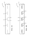
- FIGS. 4A and 4B are top views of, respectively, a partially formed and fully formed distributor for the heat exchanger of FIG. 1 in accordance with one embodiment
- FIGS. 5A, 5B, and 5C are, respectively, a top view, a side view and a sectional end view of a distributor for the heat exchanger of FIG. 4B ;
- FIGS. 6A and 6B are, respectively, a top view and sectional side view of a distributor for the heat exchanger of FIG. 1 in accordance with one embodiment.
- FIG. 1 illustrates a non-limiting example of a heat exchanger 10 .
- the examples presented herein are generally directed to an evaporator used in a vehicle air-conditioning system. However, it is contemplated that the teachings presented herein to reduce impingent noise and more uniformly distribute coolant or refrigerant are applicable to other types of heat exchangers.
- the heat exchanger 10 includes a header 20 (a.k.a. manifold) configured to define an inlet 12 for the heat exchanger 10 . While not shown, it is contemplated that the inlet 12 may include a flange or pressure regulator, as will be recognized by those in the art.
- the heat exchanger 10 also includes a plurality of tubes 14 extending away from and fluidicly coupled to the header 20 . Typically, other ends (not shown) of the tubes 14 are coupled to another header (not shown), as will be recognized by those in the art. In this example, refrigerant 16 is illustrated as flowing upward from the distributor tube.
- the velocity of the refrigerant emitted from the openings of the distributor causes it to contact the inner surface of the upper portion off the header and then flow to the bottom of the header, and enter the refrigerant tubes.
- the flow may be directed straight upwards or it may also be directed some angle from vertical. These angles include 45 degrees in the positive and negative directions from vertical.
- the heat exchanger 10 includes a distributor 22 located within the header 20 .
- the header 20 is configured to distribute refrigerant 16 flowing along a longitudinal axis 18 from the inlet 12 to the tubes 14 via a plurality of openings 24 defined by the distributor 22 through a wall 26 of the distributor 22 .
- the openings 24 include a first opening 30 configured to direct refrigerant in a first direction 32 , and a second opening 34 configured to direct refrigerant in a second direction 36 , wherein the first direction 32 and the second direction 36 are selected such that refrigerant 16 emitted from the first opening 30 and the second opening 34 substantially intersect.
- substantially intersect means that streams or jets of refrigerant are aimed by the first opening 30 and the second opening 34 such a majority, at least 75% for example, of refrigerant emitted from the first opening 30 crosses paths with a majority of refrigerant emitted from the second opening 34 before the refrigerant emitted by either opening impinges on an inner surface 28 of the header.
- the refrigerant 16 from adjacent openings collide and thereby dissipate kinetic energy. It has been observed that by crossing or intersecting the streams or jet of refrigerant emitted by adjacent openings, the jet impingement energy on the manifold is reduced.
- the openings 24 may be configured to emit a ‘pencil stream’ or relatively focused jet of refrigerant, or a relatively distributed pattern such as a conical or fan pattern.
- the degree of noise reduction is particularly evident when the pencil stream from one opening is aimed to intersect or cross paths with the pencil stream from another opening. However, noise reduction is still realized if the pattern of refrigerant emitted by an opening is less focused (i.e. more spread out) as compared to the pencil stream.
- the first direction 32 and the second direction 36 may be selected such that refrigerant emitted from the first opening 30 and the second opening 34 substantially intersect a location characterized by a radial distance 38 away from the distributor.
- the radial distance 38 is preferably selected so the streams from the openings cross or intersect well before they impinge on the inner surface 28 so the noise reduction benefits of intersecting the streams are well realized.
- the configuration of the distributor is not limited to a tubular shape.
- the distributor may be formed by rolling sheet metal into a tube shape and forming a weld seam parallel to the longitudinal axis 18 . As will become apparent in the further description of the distributor that follows, this process may be advantageous so the openings 24 can be partially or fully formed prior to rolling the sheet metal into a tubular shape.
- the distributor 22 may start out more like a pipe or other closed shape, and have the openings 24 formed by, for example, drilling the openings 24 into the pipe and through the wall 26 .
- FIGS. 2A and 2B illustrate a non-limiting example of a portion of the distributor 22 .
- the openings 24 are similar to what would be provided by drilling. That is, the openings 24 are round and oriented at some angle relative to the longitudinal axis 18 .
- the first opening 30 may be generally characterized by a first drilled passageway 40 through the wall 26 , wherein a first angle 42 of the first drilled passageway 40 determines the first direction 32 .
- the second opening 34 may be generally characterized by a second drilled passageway 44 through the wall 26 at a second angle 46 .
- the second angle may be characterized as complementary to the first angle relative to the longitudinal axis 18 .
- complementary means that the magnitudes of the first angle 42 and the second angle 46 are equal, or as equal as is possible with typical manufacturing processes. While the openings 24 in this example are characterized as being drilled, it is contemplated that similar openings could be formed by broaching, punching, or piercing; and so may be a shape other than round, as will be recognized by those in the art.
- FIGS. 3A and 3B illustrate a non-limiting example of a portion of the distributor 22 that includes a third opening 50 configured to direct refrigerant in a third direction 52 .
- the first opening 30 , the second opening 34 , and the third opening 50 are arranged to form a triangle as can be seen. Accordingly, the first direction 32 , the second direction 36 , and the third direction 52 are selected such that refrigerant 16 emitted from the first opening 30 , the second opening 34 , and the third opening 50 all substantially intersect before impinging on the inner surface 28 ( FIG. 1 ) of the header 20 .
- FIGS. 4A, 4B, 5A, 5B, and 5C illustrate a non-limiting example of a portion of the distributor 22 where the openings 24 are formed by first cutting, broaching, stamping, or otherwise machining the slots 54 into the material used to form the distributor 22 .
- the slots 54 may be formed prior to rolling sheet metal into the desired shape for the distributor 22 , or the slots 54 may be formed into shaped material such as a pipe used to fabricate the distributor 22 .
- the surface viewed in FIGS. 4A and 4B is preferably curved so a subsequent processing step can be used to collapse or pinch the slot 54 and thereby form the first opening 30 and the second opening 34 illustrated in FIG. 5A .
- the first opening 30 and the second opening 34 are formed from a slot 54 defined by the distributor 22 through the wall 26 .
- the first opening 30 may be characterized as proximate to a first end 56 of the slot 54
- the second opening 34 may be characterized as proximate to a second end 58 of the slot 54 .
- the first opening 30 is segregated from the second opening 34 when the wall 26 proximate to the slot 54 is deformed as illustrated in FIGS. 5A-5C .
- the distributor 22 may be deformed as illustrated by supporting the distributor 22 in a cradle like tool and pressing a suitably shaped tool to pinch the edges of the slot 54 together and thereby segregate the first opening 30 from the second opening 34 .
- FIGS. 6A and 6B illustrate a non-limiting example of a portion of the distributor 22 where the first opening 30 is defined by a first tab 60 formed from the wall 26 .
- the first tab 60 is preferably formed in the material used for the distributor 22 while the material still in a flat state, i.e. prior to rolling into a tubular shape. However, it is recognized that machining processes are available to form the first tab 60 into a preformed tubular shape.
- the first tab 60 is oriented in a first orientation and the second opening 34 is defined by a second tab 62 formed from the wall 26 and oriented in a second orientation complementary (e.g. opposite) to the first orientation relative to the longitudinal axis 18 . That is, the first tab 60 and the second tab 62 are oriented so the first direction 32 and the second direction 36 are selected such that refrigerant 16 emitted from the first opening 30 and the second opening 34 substantially intersect.
- a heat exchanger 10 and a distributor 22 for the heat exchanger 10 are provided.
- the momentum of the jet or stream of refrigerant is reduced from the openings 24 .
- the impingement energy of the refrigerant 16 impinging on the header 20 is reduced. This provides for reduced noise and better atomized spray to enhance refrigerant distribution in the heat exchanger 10 .
Landscapes
- Engineering & Computer Science (AREA)
- Physics & Mathematics (AREA)
- Thermal Sciences (AREA)
- Mechanical Engineering (AREA)
- General Engineering & Computer Science (AREA)
- Details Of Heat-Exchange And Heat-Transfer (AREA)
Abstract
Description
Claims (11)
Priority Applications (2)
| Application Number | Priority Date | Filing Date | Title |
|---|---|---|---|
| US14/487,244 US10072900B2 (en) | 2014-09-16 | 2014-09-16 | Heat exchanger distributor with intersecting streams |
| EP15181525.5A EP2998137A1 (en) | 2014-09-16 | 2015-08-19 | Heat exchanger distributor with intersecting streams |
Applications Claiming Priority (1)
| Application Number | Priority Date | Filing Date | Title |
|---|---|---|---|
| US14/487,244 US10072900B2 (en) | 2014-09-16 | 2014-09-16 | Heat exchanger distributor with intersecting streams |
Publications (2)
| Publication Number | Publication Date |
|---|---|
| US20160076822A1 US20160076822A1 (en) | 2016-03-17 |
| US10072900B2 true US10072900B2 (en) | 2018-09-11 |
Family
ID=54011552
Family Applications (1)
| Application Number | Title | Priority Date | Filing Date |
|---|---|---|---|
| US14/487,244 Expired - Fee Related US10072900B2 (en) | 2014-09-16 | 2014-09-16 | Heat exchanger distributor with intersecting streams |
Country Status (2)
| Country | Link |
|---|---|
| US (1) | US10072900B2 (en) |
| EP (1) | EP2998137A1 (en) |
Cited By (2)
| Publication number | Priority date | Publication date | Assignee | Title |
|---|---|---|---|---|
| US20220316804A1 (en) * | 2019-02-04 | 2022-10-06 | Mitsubishi Electric Corporation | Heat exchanger and air-conditioning apparatus including the same |
| EP4513122A4 (en) * | 2022-04-20 | 2025-06-04 | Mitsubishi Electric Corporation | HEAT EXCHANGER AND AIR CONDITIONING DEVICE |
Families Citing this family (11)
| Publication number | Priority date | Publication date | Assignee | Title |
|---|---|---|---|---|
| US20160061497A1 (en) * | 2013-11-01 | 2016-03-03 | Delphi Technologies, Inc. | Two-pass evaporator |
| US10197312B2 (en) * | 2014-08-26 | 2019-02-05 | Mahle International Gmbh | Heat exchanger with reduced length distributor tube |
| CN106568242A (en) * | 2016-11-02 | 2017-04-19 | 西安交通大学 | Liquid film distributor for multi-row horizontal pipe bundles |
| FR3059413A1 (en) * | 2016-11-30 | 2018-06-01 | Valeo Systemes Thermiques | HEAT EXCHANGER COMPRISING A REFRIGERANT FLUID CIRCUIT |
| FR3059404B1 (en) | 2016-11-30 | 2019-09-13 | Valeo Systemes Thermiques | DEVICE FOR DISPENSING A REFRIGERANT FLUID INSIDE A COLLECTOR BOX OF A HEAT EXCHANGER FOR AN AIR CONDITIONING INSTALLATION OF A VEHICLE |
| EP3438596B1 (en) * | 2017-08-01 | 2020-04-08 | Provides Metalmeccanica S.r.l. | Improved fluid distributor |
| CN107490213A (en) * | 2017-08-01 | 2017-12-19 | 南京创维家用电器有限公司 | A kind of cooling heat exchange device and its refrigerator |
| CN107985010A (en) * | 2017-11-30 | 2018-05-04 | 博耐尔汽车电气系统有限公司 | A kind of automobile air-conditioning pipe path built-in muffler |
| CN110319716B (en) * | 2019-05-16 | 2024-03-01 | 北京市京科伦冷冻设备有限公司 | Flash evaporation type closed heat exchanger |
| CN112013710A (en) * | 2019-05-31 | 2020-12-01 | 浙江三花智能控制股份有限公司 | Distribution pipe and heat exchanger |
| JP7142806B1 (en) * | 2021-10-15 | 2022-09-27 | 三菱電機株式会社 | Distributors, heat exchangers and heat pump devices |
Citations (35)
| Publication number | Priority date | Publication date | Assignee | Title |
|---|---|---|---|---|
| US1966572A (en) * | 1932-07-29 | 1934-07-17 | Colt S Mfg Co | Jet device for washing machines |
| US3466980A (en) * | 1966-02-09 | 1969-09-16 | Windmoeller & Hoelscher | Process and apparatus for manufacturing crossed-bottom sacks from plastics material sheeting |
| US3818984A (en) * | 1972-01-31 | 1974-06-25 | Nippon Denso Co | Heat exchanger |
| US3976128A (en) * | 1975-06-12 | 1976-08-24 | Ford Motor Company | Plate and fin heat exchanger |
| US5419391A (en) * | 1991-04-05 | 1995-05-30 | Westinghouse Electric Corporation | Steam generator with axial flow preheater |
| US5987893A (en) * | 1997-08-02 | 1999-11-23 | Curamik Electronics Gmbh | Heat exchanger arrangement and cooling system with at least one such heat exchanger arrangement |
| JP2000292077A (en) | 1999-02-03 | 2000-10-20 | Nippon Soken Inc | Heat exchanger |
| US6158503A (en) * | 1997-11-10 | 2000-12-12 | Valeo Thermique Moteur | Air conditioning condenser having a fluid tank with interchangeable cartridge |
| US6367265B1 (en) * | 1999-06-28 | 2002-04-09 | Kabushiki Kaisha Kobe Seiko Sho. | Vaporizer for a low temperature liquid |
| US20030010483A1 (en) * | 2001-07-13 | 2003-01-16 | Yasuo Ikezaki | Plate type heat exchanger |
| US6729386B1 (en) * | 2001-01-22 | 2004-05-04 | Stanley H. Sather | Pulp drier coil with improved header |
| US20060070401A1 (en) * | 2004-10-01 | 2006-04-06 | Advanced Heat Transfer, Llc | Refrigerant distribution device and method |
| US20070039724A1 (en) * | 2005-08-18 | 2007-02-22 | Trumbower Michael W | Evaporating heat exchanger |
| US20080092587A1 (en) * | 2005-02-02 | 2008-04-24 | Carrier Corporation | Heat Exchanger with Fluid Expansion in Header |
| US20080289806A1 (en) * | 2005-02-02 | 2008-11-27 | Carrier Corporation | Heat Exchanger with Perforated Plate in Header |
| WO2009139998A2 (en) | 2008-05-16 | 2009-11-19 | Carrier Corporation | Microchannel heat exchanger with enhanced refrigerant distribution |
| US20100282454A1 (en) * | 2006-11-13 | 2010-11-11 | Carrier Corporation | Minichannel heat exchanger header insert for distribution |
| US20110017438A1 (en) * | 2009-07-23 | 2011-01-27 | Danfoss Sanhua (Hangzhou) Micro Channel Heat Exchanger Co., Ltd. | Multi-channel heat exchanger with improved uniformity of refrigerant fluid distribution |
| US20110127023A1 (en) * | 2008-07-10 | 2011-06-02 | Taras Michael F | Design characteristics for heat exchangers distribution insert |
| US20110203780A1 (en) * | 2010-02-22 | 2011-08-25 | Danfoss Sanhua (Hangzhou) Micro Channel Heat Exchanger Co., Ltd. | Heat exchanger |
| US20110290465A1 (en) * | 2010-06-01 | 2011-12-01 | Delphi Technologies, Inc. | Orientation insensitive refrigerant distributor tube |
| WO2013054540A1 (en) * | 2011-10-14 | 2013-04-18 | パナソニック株式会社 | Finned tube heat exchanger |
| US20130199764A1 (en) * | 2010-09-13 | 2013-08-08 | Danfoss A/S | Refrigerant guiding pipe and heat exchanger having refrigerant guiding pipe |
| US8522449B2 (en) * | 2007-12-19 | 2013-09-03 | Altentech Power Inc. | Dryer for fuel material |
| US20130248158A1 (en) * | 2010-12-08 | 2013-09-26 | Qiang Gao | Method for manufacturing refrigerant guide tube of heat exchanger, refrigerant guide tube manufactured using the method and heat exchanger with the refrigerant guide tube |
| JP2013221681A (en) * | 2012-04-16 | 2013-10-28 | Panasonic Corp | Fin tube heat exchanger |
| JP2013221680A (en) * | 2012-04-16 | 2013-10-28 | Panasonic Corp | Fin tube heat exchanger |
| US20140102673A1 (en) * | 2012-10-11 | 2014-04-17 | Carrier Corporation | Heat transfer enhancement for a condensing furnace |
| WO2015027681A1 (en) | 2013-08-27 | 2015-03-05 | 杭州三花微通道换热器有限公司 | Refrigerant allocation component, collecting pipe assembly, and heat exchanger |
| US9027676B2 (en) * | 2011-07-19 | 2015-05-12 | Kobelco Construction Machinery Co., Ltd. | Construction machine |
| US9234604B2 (en) * | 2011-12-06 | 2016-01-12 | Hyundai Motor Company | Heat exchanger for vehicle |
| US20160061497A1 (en) * | 2013-11-01 | 2016-03-03 | Delphi Technologies, Inc. | Two-pass evaporator |
| US20160169596A1 (en) * | 2013-05-22 | 2016-06-16 | Daikin Industries, Ltd. | Heat exchanger |
| US20160298887A1 (en) * | 2013-08-12 | 2016-10-13 | Carrier Corporation | Heat exchanger and flow distributor |
| US9528778B2 (en) * | 2010-09-13 | 2016-12-27 | Sanhua (Hangzhou) Micro Channel Heat Exchanger Co., Ltd. | Refrigerant guiding pipe and heat exchanger having refrigerant guiding pipe |
Family Cites Families (3)
| Publication number | Priority date | Publication date | Assignee | Title |
|---|---|---|---|---|
| CN101487669B (en) * | 2008-01-17 | 2012-08-22 | 开利公司 | Heat exchanger comprising multi-pipe distributer |
| KR101372096B1 (en) * | 2011-11-18 | 2014-03-07 | 엘지전자 주식회사 | A heat exchanger |
| EP2948725B1 (en) * | 2013-01-24 | 2016-08-17 | Alcoil USA LLC | Heat exchanger |
-
2014
- 2014-09-16 US US14/487,244 patent/US10072900B2/en not_active Expired - Fee Related
-
2015
- 2015-08-19 EP EP15181525.5A patent/EP2998137A1/en not_active Withdrawn
Patent Citations (37)
| Publication number | Priority date | Publication date | Assignee | Title |
|---|---|---|---|---|
| US1966572A (en) * | 1932-07-29 | 1934-07-17 | Colt S Mfg Co | Jet device for washing machines |
| US3466980A (en) * | 1966-02-09 | 1969-09-16 | Windmoeller & Hoelscher | Process and apparatus for manufacturing crossed-bottom sacks from plastics material sheeting |
| US3818984A (en) * | 1972-01-31 | 1974-06-25 | Nippon Denso Co | Heat exchanger |
| US3976128A (en) * | 1975-06-12 | 1976-08-24 | Ford Motor Company | Plate and fin heat exchanger |
| US5419391A (en) * | 1991-04-05 | 1995-05-30 | Westinghouse Electric Corporation | Steam generator with axial flow preheater |
| US5987893A (en) * | 1997-08-02 | 1999-11-23 | Curamik Electronics Gmbh | Heat exchanger arrangement and cooling system with at least one such heat exchanger arrangement |
| US6158503A (en) * | 1997-11-10 | 2000-12-12 | Valeo Thermique Moteur | Air conditioning condenser having a fluid tank with interchangeable cartridge |
| JP2000292077A (en) | 1999-02-03 | 2000-10-20 | Nippon Soken Inc | Heat exchanger |
| US6367265B1 (en) * | 1999-06-28 | 2002-04-09 | Kabushiki Kaisha Kobe Seiko Sho. | Vaporizer for a low temperature liquid |
| US6729386B1 (en) * | 2001-01-22 | 2004-05-04 | Stanley H. Sather | Pulp drier coil with improved header |
| US20030010483A1 (en) * | 2001-07-13 | 2003-01-16 | Yasuo Ikezaki | Plate type heat exchanger |
| US20060070401A1 (en) * | 2004-10-01 | 2006-04-06 | Advanced Heat Transfer, Llc | Refrigerant distribution device and method |
| US20080092587A1 (en) * | 2005-02-02 | 2008-04-24 | Carrier Corporation | Heat Exchanger with Fluid Expansion in Header |
| US20080289806A1 (en) * | 2005-02-02 | 2008-11-27 | Carrier Corporation | Heat Exchanger with Perforated Plate in Header |
| US20070039724A1 (en) * | 2005-08-18 | 2007-02-22 | Trumbower Michael W | Evaporating heat exchanger |
| US20100282454A1 (en) * | 2006-11-13 | 2010-11-11 | Carrier Corporation | Minichannel heat exchanger header insert for distribution |
| US8522449B2 (en) * | 2007-12-19 | 2013-09-03 | Altentech Power Inc. | Dryer for fuel material |
| WO2009139998A2 (en) | 2008-05-16 | 2009-11-19 | Carrier Corporation | Microchannel heat exchanger with enhanced refrigerant distribution |
| US20110127023A1 (en) * | 2008-07-10 | 2011-06-02 | Taras Michael F | Design characteristics for heat exchangers distribution insert |
| US20110017438A1 (en) * | 2009-07-23 | 2011-01-27 | Danfoss Sanhua (Hangzhou) Micro Channel Heat Exchanger Co., Ltd. | Multi-channel heat exchanger with improved uniformity of refrigerant fluid distribution |
| US20110203780A1 (en) * | 2010-02-22 | 2011-08-25 | Danfoss Sanhua (Hangzhou) Micro Channel Heat Exchanger Co., Ltd. | Heat exchanger |
| US20110290465A1 (en) * | 2010-06-01 | 2011-12-01 | Delphi Technologies, Inc. | Orientation insensitive refrigerant distributor tube |
| US20130199764A1 (en) * | 2010-09-13 | 2013-08-08 | Danfoss A/S | Refrigerant guiding pipe and heat exchanger having refrigerant guiding pipe |
| US9528778B2 (en) * | 2010-09-13 | 2016-12-27 | Sanhua (Hangzhou) Micro Channel Heat Exchanger Co., Ltd. | Refrigerant guiding pipe and heat exchanger having refrigerant guiding pipe |
| US20130248158A1 (en) * | 2010-12-08 | 2013-09-26 | Qiang Gao | Method for manufacturing refrigerant guide tube of heat exchanger, refrigerant guide tube manufactured using the method and heat exchanger with the refrigerant guide tube |
| US9027676B2 (en) * | 2011-07-19 | 2015-05-12 | Kobelco Construction Machinery Co., Ltd. | Construction machine |
| JPWO2013054540A1 (en) * | 2011-10-14 | 2015-03-30 | パナソニックIpマネジメント株式会社 | Finned tube heat exchanger |
| WO2013054540A1 (en) * | 2011-10-14 | 2013-04-18 | パナソニック株式会社 | Finned tube heat exchanger |
| US9234604B2 (en) * | 2011-12-06 | 2016-01-12 | Hyundai Motor Company | Heat exchanger for vehicle |
| JP2013221680A (en) * | 2012-04-16 | 2013-10-28 | Panasonic Corp | Fin tube heat exchanger |
| JP2013221681A (en) * | 2012-04-16 | 2013-10-28 | Panasonic Corp | Fin tube heat exchanger |
| US20140102673A1 (en) * | 2012-10-11 | 2014-04-17 | Carrier Corporation | Heat transfer enhancement for a condensing furnace |
| US20160169596A1 (en) * | 2013-05-22 | 2016-06-16 | Daikin Industries, Ltd. | Heat exchanger |
| US20160298887A1 (en) * | 2013-08-12 | 2016-10-13 | Carrier Corporation | Heat exchanger and flow distributor |
| WO2015027681A1 (en) | 2013-08-27 | 2015-03-05 | 杭州三花微通道换热器有限公司 | Refrigerant allocation component, collecting pipe assembly, and heat exchanger |
| US20160209091A1 (en) * | 2013-08-27 | 2016-07-21 | Sanhua (Hangzhou) Micro Channel Heat Exchanger Co. Ltd. | Refrigerant distributing component, header assembly, and heat exchanger |
| US20160061497A1 (en) * | 2013-11-01 | 2016-03-03 | Delphi Technologies, Inc. | Two-pass evaporator |
Cited By (3)
| Publication number | Priority date | Publication date | Assignee | Title |
|---|---|---|---|---|
| US20220316804A1 (en) * | 2019-02-04 | 2022-10-06 | Mitsubishi Electric Corporation | Heat exchanger and air-conditioning apparatus including the same |
| US12044480B2 (en) * | 2019-02-04 | 2024-07-23 | Mitsubishi Electric Corporation | Heat exchanger and air-conditioning apparatus including the same |
| EP4513122A4 (en) * | 2022-04-20 | 2025-06-04 | Mitsubishi Electric Corporation | HEAT EXCHANGER AND AIR CONDITIONING DEVICE |
Also Published As
| Publication number | Publication date |
|---|---|
| US20160076822A1 (en) | 2016-03-17 |
| EP2998137A1 (en) | 2016-03-23 |
Similar Documents
| Publication | Publication Date | Title |
|---|---|---|
| US10072900B2 (en) | Heat exchanger distributor with intersecting streams | |
| EP2362176B1 (en) | Micro-channel heat exchanger with adjustable distribution pipe | |
| US10126066B2 (en) | Side mounted refrigerant distributor in a flooded evaporator and side mounted inlet pipe to the distributor | |
| US20230332783A1 (en) | Steam dispersion system | |
| EP3098386B1 (en) | Impingement sleeve and method of forming an impingement sleeve | |
| JP2011169496A (en) | Refrigerant distributor | |
| US11892206B2 (en) | Heat exchanger and refrigeration cycle apparatus | |
| EP3314189B1 (en) | Microtube heat exchanger | |
| US20100003019A1 (en) | Humidifier Unit | |
| JP2015092120A (en) | Condenser | |
| KR20220101401A (en) | Fin tube heat exchanger | |
| US20190017752A1 (en) | Folded conduit for heat exchanger applications | |
| CN112543842B (en) | Steam bypass inlet | |
| JP6152755B2 (en) | Loop heat pipe | |
| CN204115315U (en) | Refrigerant distributor and HVAC system | |
| US8782896B2 (en) | Method for the manufacture of an ejector nozzle tube | |
| JP6094646B2 (en) | Refrigeration unit heat source unit | |
| JP2017040459A (en) | Heat source unit of refrigeration device | |
| US11747064B2 (en) | Integrated oil separator with flow management | |
| US12140326B2 (en) | Heat exchanger and air conditioner including the same | |
| JP2006231145A (en) | Temperature reduction tower for exhaust gas treatment | |
| WO2021006826A1 (en) | Production of multi-directional lower connection apparatus from full material by cold forging method for radiant panel heating systems | |
| JP2015127596A (en) | Air conditioner outdoor unit | |
| JP2006071173A (en) | Evaporator | |
| JP7079478B2 (en) | Double tube heat exchanger |
Legal Events
| Date | Code | Title | Description |
|---|---|---|---|
| AS | Assignment |
Owner name: DELPHI TECHNOLOGIES, INC., MICHIGAN Free format text: ASSIGNMENT OF ASSIGNORS INTEREST;ASSIGNORS:PETTITT, EDWARD D.;KOWSKY, CARRIE M.;REEL/FRAME:033838/0716 Effective date: 20140828 |
|
| AS | Assignment |
Owner name: MAHLE INTERNATIONAL GMBH, GERMANY Free format text: ASSIGNMENT OF ASSIGNORS INTEREST;ASSIGNOR:DELPHI TECHNOLOGIES, INC.;REEL/FRAME:037640/0036 Effective date: 20150701 |
|
| STCF | Information on status: patent grant |
Free format text: PATENTED CASE |
|
| FEPP | Fee payment procedure |
Free format text: MAINTENANCE FEE REMINDER MAILED (ORIGINAL EVENT CODE: REM.); ENTITY STATUS OF PATENT OWNER: LARGE ENTITY |
|
| LAPS | Lapse for failure to pay maintenance fees |
Free format text: PATENT EXPIRED FOR FAILURE TO PAY MAINTENANCE FEES (ORIGINAL EVENT CODE: EXP.); ENTITY STATUS OF PATENT OWNER: LARGE ENTITY |
|
| STCH | Information on status: patent discontinuation |
Free format text: PATENT EXPIRED DUE TO NONPAYMENT OF MAINTENANCE FEES UNDER 37 CFR 1.362 |
|
| FP | Lapsed due to failure to pay maintenance fee |
Effective date: 20220911 |