US10072781B2 - Crimpable separable tubing clamp - Google Patents
Crimpable separable tubing clamp Download PDFInfo
- Publication number
- US10072781B2 US10072781B2 US14/222,382 US201414222382A US10072781B2 US 10072781 B2 US10072781 B2 US 10072781B2 US 201414222382 A US201414222382 A US 201414222382A US 10072781 B2 US10072781 B2 US 10072781B2
- Authority
- US
- United States
- Prior art keywords
- band portion
- crimpable
- pair
- compression clamp
- outer band
- Prior art date
- Legal status (The legal status is an assumption and is not a legal conclusion. Google has not performed a legal analysis and makes no representation as to the accuracy of the status listed.)
- Active, expires
Links
- 230000006835 compression Effects 0.000 claims abstract description 52
- 238000007906 compression Methods 0.000 claims abstract description 52
- 239000000725 suspension Substances 0.000 claims description 8
- 230000003014 reinforcing effect Effects 0.000 claims description 5
- 210000002445 nipple Anatomy 0.000 description 4
- 238000002788 crimping Methods 0.000 description 3
- 238000010276 construction Methods 0.000 description 2
- 239000000463 material Substances 0.000 description 2
- 238000000034 method Methods 0.000 description 2
- 230000008602 contraction Effects 0.000 description 1
- 238000004519 manufacturing process Methods 0.000 description 1
- 238000012986 modification Methods 0.000 description 1
- 230000004048 modification Effects 0.000 description 1
- 238000005457 optimization Methods 0.000 description 1
- 238000007789 sealing Methods 0.000 description 1
- 238000000926 separation method Methods 0.000 description 1
- 238000006467 substitution reaction Methods 0.000 description 1
- 230000007704 transition Effects 0.000 description 1
Images


Classifications
-
- F—MECHANICAL ENGINEERING; LIGHTING; HEATING; WEAPONS; BLASTING
- F16—ENGINEERING ELEMENTS AND UNITS; GENERAL MEASURES FOR PRODUCING AND MAINTAINING EFFECTIVE FUNCTIONING OF MACHINES OR INSTALLATIONS; THERMAL INSULATION IN GENERAL
- F16L—PIPES; JOINTS OR FITTINGS FOR PIPES; SUPPORTS FOR PIPES, CABLES OR PROTECTIVE TUBING; MEANS FOR THERMAL INSULATION IN GENERAL
- F16L33/00—Arrangements for connecting hoses to rigid members; Rigid hose-connectors, i.e. single members engaging both hoses
- F16L33/02—Hose-clips
- F16L33/025—Hose-clips tightened by deforming radially extending loops or folds
-
- Y—GENERAL TAGGING OF NEW TECHNOLOGICAL DEVELOPMENTS; GENERAL TAGGING OF CROSS-SECTIONAL TECHNOLOGIES SPANNING OVER SEVERAL SECTIONS OF THE IPC; TECHNICAL SUBJECTS COVERED BY FORMER USPC CROSS-REFERENCE ART COLLECTIONS [XRACs] AND DIGESTS
- Y10—TECHNICAL SUBJECTS COVERED BY FORMER USPC
- Y10T—TECHNICAL SUBJECTS COVERED BY FORMER US CLASSIFICATION
- Y10T24/00—Buckles, buttons, clasps, etc.
- Y10T24/14—Bale and package ties, hose clamps
- Y10T24/1457—Metal bands
- Y10T24/1478—Circumferentially swagged band clamp
Definitions
- a THIRD EXAMPLE as shown in FIG. 1, U.S. Pat. No. 4,299,012, Issued on Nov. 10, 1981, to Oetiker teaches a hose clamp 10 that includes a narrow tongue-like extension 12 at the end of the full-width inner band portion 14 adapted to engage through a through opening 16 that commences in the outer band portion 18 at the beginning of a step-like portion 20.
- a typical “Oetiker” ear generally designated by reference numeral 22, which consists of two parallel outwardly extending leg portions 24 and 26 interconnected by a bridging portion 28 and provided with a reinforcing groove 30.
- the mechanical connection consists of a so-called guide or suspension hook 32 and of two cold-deformed, deep-drawn support hooks 34 adapted to engage in through apertures 36 in the outer band portion 18.
- U.S. Pat. No. 4,315,348, Issued on Feb. 16, 1982, to Oetiker teaches a clamp structure with a clamping band and with at least one plastically deformable so-called “Oetiker” ear to be contracted to tighten the clamp structure about the object to be fastened, to assure a substantially smooth, gap-free transition in the circumferential direction within the area of overlap, for example, of an inner and outer band portion in the area of mechanical interlock or of an insert member and corresponding parts of the clamping band, a tongue portion is provided at each free end of the inner part which is adapted to engage in a corresponding aperture in the respective outer part when the ear is contracted.
- a SIXTH EXAMPLE U.S. Pat. No. 4,583,773, Issued on Apr. 22, 1986, to Janssen, et al. teaches a releasable tubular clamp for connecting cylindrical or profile tubes.
- a longitudinally running longitudinal rib open towards the interior is provided which prior to clamping exhibits a U-shaped (ear-shaped) cross section and whose legs after clamping abut in parts whereby the clamping jacket in an adjoining area exhibits a cross section deviating from a circular contour.
- a SEVENTH EXAMPLE U.S. Pat. No. 4,948,178, Issued on Aug. 14, 1990, to Sauer teaches a hose fitting wherein the free end of a nipple or pipe is sealingly held in one end portion of a hose by a sleeve having a tubular body with a single axially parallel slot and one or more bridges extending across the slot at the exterior of the tubular body.
- the latter has depressions that extend toward the nipple or pipe to urge the end portion of the hose into sealing engagement with the nipple or pipe.
- the sleeve can be detached from the end portion of the hose by partially or fully destroying, by deforming, or by removing the bridge or bridges so that the slot can be widened prior to separation of the sleeve from the hose.
- a TENTH EXAMPLE U.S. Patent Office Document No. 2008/0012303, Published on Jan. 17, 2008, to Poll, et al. teaches a one-piece unitary compression clamp for securing a pipe or tube on a fitting.
- the clamp may include at least one inward deformation that provides an interference fit between the clamp and the pipe or tube. Consequently, the clamp cannot fall off the pipe or tube before being permanently crimped, and the fitting is prevented from falling out of the tube.
- the clamp includes an ear for crimping the clamp to the tube, and a tongue within the clamp and overlying the mouth of the ear to provide uniform compression around the entire tube.
- the clamp includes stop tabs that hold the pipe at a stand-off from the end of the clamp.
- Axial compression of a first split driver and a second split driver against the ends of the grounding clamp facilitates electrical contact between the outer shell and the conductive bonding contact and between the conductive bonding contact and the outer conductive portion of the coaxial cable. Furthermore, an associated method for maintaining ground continuity is also taught.
- STILL ANOTHER OBJECT of the present invention is to provide a crimpable separable tubing clamp that is simple to use.
- FIG. 3 is a diagrammatic perspective view showing the crimpable separable tubing clamp being assembled placed at an appropriate pipe joint;
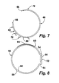
- FIG. 7 is a plan view taken in the direction of arrow 7 of just an inner component shown in FIG. 6 ;
- FIG. 8 is a plan view taken in the direction of arrow 8 of just an outer component shown in FIG. 6 ;
- the configuration of the crimpable compression clamp 40 can best be seen in FIGS. 2, 6, 7, 8, and 9 , and as such, will be discussed with reference thereto.
- the outer band portion 48 further has an Oetiker ear 52 .
- the outer band portion 48 further has a step-like portion 60 .
- the outer band portion 48 further has a through opening 64 .
- Each pair of support hooks 68 of the inner band portion 46 releasably engage in an associated pair of through apertures 62 of the outer band portion 48 .
Landscapes
- Engineering & Computer Science (AREA)
- General Engineering & Computer Science (AREA)
- Mechanical Engineering (AREA)
- Clamps And Clips (AREA)
Abstract
A crimpable compression clamp that secures a tube onto a fitting and is able to be installed and removed without having to separate the tube and the fitting from each other. The crimpable compression clamp includes an inner band portion and an outer band portion. The inner band portion is detachably attached in the outer band portion so as to allow the crimpable compression clamp to be installed and removed without having to separate the tube and the fitting from each other by merely separating the outer band portion and the inner band portion from each other.
Description
Field of the Invention
The present invention relates to a clamp, and more particularly, a crimpable separable tubing clamp.
Description of the Prior Art
Numerous innovations for clamps have been provided in the prior art that will be described. Even though these innovations may be suitable for the specific individual purposes to which they address, however, they differ from the present invention.
A FIRST EXAMPLE, U.S. Pat. No. 3,789,463, Issued on Feb. 5, 1974, to Oetiker teaches a bridging member for bridging the gap formed in the circumferential band portion of a hose clamp provided with an outwardly extending fold adapted to be contracted, whereby the bridging member includes relatively thin material and includes a base portion adapted to abut against the radially inner surface of the band and side walls extending substantially at right angle to the base portion and provided with inwardly directed projections near the outer ends which can snap-in behind the outer surface of the band and thereby hold the bridging member in the assembled condition.
A SECOND EXAMPLE, U.S. Pat. No. 3,869,944, Issued on Mar. 11, 1975, to Detiker teaches a clamp for clamping a hose onto a nipple by way of an open band adapted to locked, with apparatus for the contraction of the ends of the band. To that end the band is provided with perforation apertures in the upper band end and with barbs in the lower band end which engage in the perforation apertures when the band is placed about the hose. Perforation apertures are also provided in the lower band end while a slot is provided in the upper band end within the area of the second-mentioned perforation apertures. The boundary wall of the slot is thereby provided within the area of its surface pointing away from the upper band end with an upset portion extending upwardly, i.e., outwardly.
A THIRD EXAMPLE, as shown in FIG. 1, U.S. Pat. No. 4,299,012, Issued on Nov. 10, 1981, to Oetiker teaches a hose clamp 10 that includes a narrow tongue-like extension 12 at the end of the full-width inner band portion 14 adapted to engage through a through opening 16 that commences in the outer band portion 18 at the beginning of a step-like portion 20. In addition to a typical “Oetiker” ear generally designated by reference numeral 22, which consists of two parallel outwardly extending leg portions 24 and 26 interconnected by a bridging portion 28 and provided with a reinforcing groove 30. The mechanical connection consists of a so-called guide or suspension hook 32 and of two cold-deformed, deep-drawn support hooks 34 adapted to engage in through apertures 36 in the outer band portion 18.
A FOURTH EXAMPLE, U.S. Pat. No. 4,315,348, Issued on Feb. 16, 1982, to Oetiker teaches a clamp structure with a clamping band and with at least one plastically deformable so-called “Oetiker” ear to be contracted to tighten the clamp structure about the object to be fastened, to assure a substantially smooth, gap-free transition in the circumferential direction within the area of overlap, for example, of an inner and outer band portion in the area of mechanical interlock or of an insert member and corresponding parts of the clamping band, a tongue portion is provided at each free end of the inner part which is adapted to engage in a corresponding aperture in the respective outer part when the ear is contracted.
A FIFTH EXAMPLE, U.S. Pat. No. 4,451,955, Issued on Jun. 5, 1984, to Kern, et al. teaches a crimp-type hose clamp wherein the ends of the clamp are joined in a double-layered top portion of the hat section of the clamp.
A SIXTH EXAMPLE, U.S. Pat. No. 4,583,773, Issued on Apr. 22, 1986, to Janssen, et al. teaches a releasable tubular clamp for connecting cylindrical or profile tubes. In order to provide a releasable tubular clamp for interconnecting cylindrical or profile tubes wherein the press force is increased and after assembly a greater degree of compactness and stiffness is present, a longitudinally running longitudinal rib open towards the interior is provided which prior to clamping exhibits a U-shaped (ear-shaped) cross section and whose legs after clamping abut in parts whereby the clamping jacket in an adjoining area exhibits a cross section deviating from a circular contour.
A SEVENTH EXAMPLE, U.S. Pat. No. 4,948,178, Issued on Aug. 14, 1990, to Sauer teaches a hose fitting wherein the free end of a nipple or pipe is sealingly held in one end portion of a hose by a sleeve having a tubular body with a single axially parallel slot and one or more bridges extending across the slot at the exterior of the tubular body. The latter has depressions that extend toward the nipple or pipe to urge the end portion of the hose into sealing engagement with the nipple or pipe. The sleeve can be detached from the end portion of the hose by partially or fully destroying, by deforming, or by removing the bridge or bridges so that the slot can be widened prior to separation of the sleeve from the hose.
AN EIGHTH EXAMPLE, U.S. Pat. No. 6,240,603, Issued on Jun. 5, 2001, to Craig, Jr. teaches a clamp made from clamping band material in which optimization for the length of the necessary blank is realized in dependence on the length of the bridging portion of a so-called “Oetiker” ear whereby this bridging portion length is used to determine the length of the overlapped full-band-width inner clamping band portion as well as the location of the beginning of the step-like portion and the length of the tongue-like extension at the end of the full-band-width inner clamping band portion.
A NINTH EXAMPLE, U.S. Pat. No. 7,360,800, Issued on Apr. 22, 2008, to Poll, et al. teaches a one-piece unitary compression clamp for securing a pipe or tube on a fitting. The clamp may include at least one inward deformation that provides an interference fit between the clamp and the pipe or tube. Consequently, the clamp cannot fall off the pipe or tube before being permanently crimped, and the fitting is prevented from falling out of the tube. In a second embodiment, the clamp includes an ear for crimping the clamp to the tube, and a tongue within the clamp and overlying the mouth of the ear to provide uniform compression around the entire tube.
A TENTH EXAMPLE, U.S. Patent Office Document No. 2008/0012303, Published on Jan. 17, 2008, to Poll, et al. teaches a one-piece unitary compression clamp for securing a pipe or tube on a fitting. The clamp may include at least one inward deformation that provides an interference fit between the clamp and the pipe or tube. Consequently, the clamp cannot fall off the pipe or tube before being permanently crimped, and the fitting is prevented from falling out of the tube. In a second embodiment, the clamp includes an ear for crimping the clamp to the tube, and a tongue within the clamp and overlying the mouth of the ear to provide uniform compression around the entire tube. In a third embodiment, the clamp includes stop tabs that hold the pipe at a stand-off from the end of the clamp.
AN ELEVENTH EXAMPLE, U.S. Patent Office Document No. 2012/0246920, Published on Oct. 4, 2012, to Montena teaches a grounding clamp positioned on a coaxial cable at a location other than an end of the coaxial cable. The grounding clamp includes an outer shell formed by the unity of a first split shell portion and a second split shell portion. The outer shell has a radial relationship with an elastomeric sleeve. The elastomeric sleeve is radially disposed over a conductive bonding contact. The conductive bonding contact is radially disposed over an outer conductive portion of the coaxial cable. Axial compression of a first split driver and a second split driver against the ends of the grounding clamp facilitates electrical contact between the outer shell and the conductive bonding contact and between the conductive bonding contact and the outer conductive portion of the coaxial cable. Furthermore, an associated method for maintaining ground continuity is also taught.
It is apparent now that numerous innovations for clamps have been provided in the prior art that adequate for various purposes. Furthermore, even though these innovations may be suitable for the specific individual purposes to which they address, accordingly, they would not be suitable for the purposes of the present invention as heretofore described.
AN OBJECT of the present invention is to provide a crimpable separable tubing clamp that avoids the disadvantages of the prior art.
ANOTHER OBJECT of the present invention is to provide a crimpable separable tubing clamp that is simple and inexpensive to manufacture.
STILL ANOTHER OBJECT of the present invention is to provide a crimpable separable tubing clamp that is simple to use.
BRIEFLY STATED, STILL YET ANOTHER OBJECT of the present invention is to provide a crimpable compression clamp that secures a tube onto a fitting and is able to be installed and removed without having to separate the tube and the fitting from each other. The crimpable compression clamp includes an inner band portion and an outer band portion. The inner band portion is detachably attached in the outer band portion so as to allow the crimpable compression clamp to be installed and removed without having to separate the tube and the fitting from each other by merely separating the outer band portion and the inner band portion from each other.
The novel features which are considered characteristic of the present invention are set forth in the appended claims. The invention itself, however, both as to its construction and its method of operation, together with additional objects and advantages thereof, will be best understood from the following description of the specific embodiments when read and understood in connection with the accompanying drawing.
The figures of the drawings are briefly described as follows:
- 10 hose clamp
- 12 tongue-like extension of
inner band portion 14 - 14 inner band portion
- 16 through opening of
outer band portion 18 - 18 outer band portion
- 20 step-like portion of
outer band portion 18 - 22 “Oetiker” ear
- 24 outwardly extending leg portion of “Oetiker”
ear 22 - 26 other outwardly extending leg portion of “Oetiker”
ear 22 - 28 bridging portion of “Oetiker”
ear 22 - 30 reinforcing through groove of bridging
portion 28 of “Oetiker”ear 22 - 32 guide or suspension hook of
inner band portion 14 - 34 two cold-deformed, deep-drawn support hooks of
inner band portion 14 - 36 through apertures of
outer band portion 18
- 40 crimpable compression clamp of embodiments of present invention for securing
tube 42 onto fitting 44 and for being able to be installed and removed without having to separatetube 42 and fitting 44 from each other - 42 tube
- 44 fitting
- 46 inner band portion
- 48 outer band portion
- 50 pair of free ends of
outer band portion 48 - 52 Oetiker ear of
outer band portion 48 - 54 pair of parallel outwardly extending leg portions of
Oetiker ear 52 ofouter band portion 48 - 56 bridge portion of
Oetiker ear 52 ofouter band portion 48 - 58 reinforcing through groove of
bridge portion 56 ofOetiker ear 52 ofouter band portion 48 - 60 step-like portion of
outer band portion 48 - 62 pair of three through apertures of
outer band portion 48 - 64 through opening of
outer band portion 48 - 66 pair of free ends of
inner band portion 46 - 68 two pair of support hooks of
inner band portion 46 - 70 tongue extension of
inner band portion 46 - 72 pair of guide or suspension hooks of
inner band portion 46
Referring now to the figures, in which like numerals indicate like parts, and particularly to FIGS. 3, 4, and 5 , the crimpable compression clamp of the embodiments of the present invention is shown generally at 40 for securing a tube 42 onto a fitting 44 and for being able to be installed and removed without having to separate the tube 42 and the fitting 44 from each other.
The configuration of the crimpable compression clamp 40 can best be seen in FIGS. 2, 6, 7, 8, and 9 , and as such, will be discussed with reference thereto.
The crimpable compression clamp 40 comprises an inner band portion 46 and an outer band portion 48. The inner band portion 46 is detachably attached in the outer band portion 48 for allowing the crimpable compression clamp 40 to be installed and removed without having to separate the tube 42 and the fitting 44 from each other by merely separating the outer band portion 48 and the inner band portion 46 from each other.
The outer band portion 48 is separate and distinct from the inner band portion 46 for allowing the crimpable compression clamp 40 to be installed and removed without having to separate the tube 42 and the fitting 44 from each other by merely separating the outer band portion 48 and the inner band portion 46 from each other.
The outer band portion 48 is generally circular, and has a pair of free ends 50.
The outer band portion 48 further has an Oetiker ear 52.
The Oetiker ear 52 of the outer band portion 48 has a pair of parallel outwardly extending leg portions 54 connected to each other by a bridge portion 56.
The bridge portion 56 of the Oetiker ear 52 of the outer band portion 48 has a reinforcing through groove 58.
The outer band portion 48 further has a step-like portion 60.
The outer band portion 48 further has a pair of three through apertures 62.
The outer band portion 48 further has a through opening 64.
The pair of free ends 50 of the outer band portion 48 are adjacent to each other and slightly spaced-apart from each other.
The step-like portion 60 of the outer band portion 48 is disposed to one side of the Oetiker ear 52 of the outer band portion 48.
Each pair of three through apertures 62 of the outer band portion 48 are disposed adjacent to an associated free end 50 of the outer band portion 48.
The through opening 64 of the outer band portion 48 is slender and elongated, and originates at the step-like portion 60 of the outer band portion 48.
The inner band portion 46 sits coaxially in the outer band portion 48.
The inner band portion 46 is generally circular, and has a pair of free ends 66.
The inner band portion 46 further has two pair of support hooks 68.
The two pair of support hooks 68 of the inner band portion 46 are two pair of cold-deformed and deep drawn support hooks.
The two pair of support hooks 68 of the inner band portion 46 are disposed adjacent one free end 66 of the inner band portion 46.
Each pair of support hooks 68 of the inner band portion 46 releasably engage in an associated pair of through apertures 62 of the outer band portion 48.
The inner band portion 46 further has a tongue extension 70.
The tongue extension 70 of the inner band portion 46 extends to the other free end 66 of the inner band portion 46.
The tongue extension 70 of the inner band portion 46 rides releasably in the through opening 64 of the outer band portion 48.
The pair of free ends 66 of the inner band portion 46 are spaced-apart from each other and face each other.
The two pair of support hooks 68 of the inner band portion 46 are disposed adjacent to one free end 66 of the inner band portion 46.
The tongue extension 70 of the inner band portion 46 is slender and elongated.
The inner band portion 46 further has a pair of guide/suspension hooks 72.
The pair of guide/suspension hooks 72 of the inner band portion 46 are disposed between the two pair of support hooks 68 of the inner band portion 46, and releasably engage in an associated pair of through apertures 62 of the outer band portion 48 that straddle the pair of free ends 50 of the outer band portion 48, and in so doing, maintains the outer band portion 48 around the inner band portion 46.
It will be understood that each of the elements described above, or two or more together, may also find a useful application in other types of constructions differing from the types described above.
While the invention has been illustrated and described as embodiments of a crimpable separable tubing clamp, accordingly it is not limited to the details shown, since it will be understood that various omissions, modifications, substitutions and changes in the forms and details of the device illustrated and its operation can be made by those skilled in the art without departing in any way from the spirit of the present invention.
Without further analysis, the foregoing will so fully reveal the gist of the present invention that others can, by applying current knowledge, readily adapt it for various applications without omitting features that, from the standpoint of prior art, fairly constitute characteristics of the generic or specific aspects of this invention.
Claims (35)
1. A crimpable compression clamp for securing a tube onto a fitting and for being able to be installed without having to separate the tube and the fitting from each other, comprising:
a) an inner band portion having a pair of free ends such that there is a space therebetween; and
b) an outer band portion having a pair of free ends such that there is a space therebetween,
wherein one of said inner band portion and said outer band portion has at least two apertures, and the other has at least two hooks that can be aligned with said apertures when assembled so as to retain said portions together such that said inner band portion is detachably attached in said outer band portion,
wherein said outer band portion substantially encompasses said pair of free ends of said inner band portion,
wherein said outer band portion has an Oetiker ear, and
wherein said outer band portion has a step-like portion.
2. The crimpable compression clamp of claim 1 , wherein said outer band portion is separate and distinct from said inner band portion.
3. The crimpable compression clamp of claim 1 , wherein said outer band portion is generally circular.
4. The crimpable compression clamp of claim 1 , wherein said Oetiker ear of said outer band portion has a pair of parallel outwardly extending leg portions and a bridge portion,
wherein said pair of parallel outwardly extending leg portions are connected to each other by said bridge portion.
5. The crimpable compression clamp of claim 1 , wherein said bridge portion of said Oetiker ear of said outer band portion has a reinforcing through groove.
6. The crimpable compression clamp of claim 1 , wherein said outer band portion has a pair of three through apertures.
7. The crimpable compression clamp of claim 6 , wherein said outer band portion has a through opening.
8. The crimpable compression clamp of claim 1 , wherein said pair of free ends of said outer band portion are adjacent to each other.
9. The crimpable compression clamp of claim 1 , wherein said pair of free ends of said outer band portion are slightly spaced-apart from each other.
10. The crimpable compression clamp of claim 1 , wherein said step-like portion of said outer band portion is disposed to one side of said Oetiker ear of said outer band portion.
11. The crimpable compression clamp of claim 6 , wherein each pair of three through apertures of said outer band portion are disposed adjacent to an associated free end of said outer band portion.
12. The crimpable compression clamp of claim 7 , wherein said through opening of said outer band portion is slender.
13. The crimpable compression clamp of claim 7 , wherein said through opening of said outer band portion is elongated.
14. The crimpable compression clamp of claim 7 , wherein said through opening of said outer band portion originates at said step-like portion of said outer band portion.
15. The crimpable compression clamp of claim 1 , wherein said inner band portion sits coaxially in said outer band portion.
16. The crimpable compression clamp of claim 1 , wherein said inner band portion is generally circular.
17. The crimpable compression clamp of claim 7 , wherein said inner band portion has two pair of support hooks.
18. The crimpable compression clamp of claim 17 , wherein said two pair of support hooks of said inner band portion are two pair of cold-deformed and deep drawn support hooks.
19. The crimpable compression clamp of claim 17 , wherein said two pair of support hooks of said inner band portion are disposed adjacent one free end of said inner band portion.
20. The crimpable compression clamp of claim 17 , wherein each pair of support hooks of said inner band portion releasably engage in an associated pair of through apertures of said outer band portion.
21. The crimpable compression clamp of claim 19 , wherein said inner band portion has a tongue extension.
22. The crimpable compression clamp of claim 21 , wherein said tongue extension of said inner band portion extends to the other free end of said inner band portion.
23. The crimpable compression clamp of claim 21 , wherein said tongue extension of said inner band portion rides releasably in said through opening of said outer band portion.
24. The crimpable compression clamp of claim 7 , wherein said pair of free ends of said inner band portion are spaced-apart from each other.
25. The crimpable compression clamp of claim 7 , wherein said pair of free ends of said inner band portion face each other.
26. The crimpable compression clamp of claim 17 , wherein each pair of support hooks of said inner band portion are disposed adjacent to one free end of said inner band portion.
27. The crimpable compression clamp of claim 21 , wherein said tongue extension of said inner band portion is slender.
28. The crimpable compression clamp of claim 21 , wherein said tongue extension of said inner band portion is elongated.
29. A crimpable compression clamp for securing a tube onto a fitting and for being able to be installed without having to separate the tube and the fitting from each other, comprising:
a) an inner band portion; and
b) an outer band portion,
wherein said inner band portion is detachably attached in said outer band portion,
wherein said outer band portion has a pair of free ends, an Oetiker ear, a step-like portion, a pair of three through apertures, and a through opening, and
wherein said inner band portion has a pair of free ends, two pair of support hooks, and a pair of guide/suspension hooks.
30. The crimpable compression clamp of claim 29 , wherein said pair of guide/suspension hooks of said inner band portion are disposed between said two pair of support hooks of said inner band portion.
31. The crimpable compression clamp of claim 29 , wherein said pair of guide/suspension hooks of said inner band portion releasably engage in an associated pair of through apertures of said outer band portion that straddle said pair of free ends of said outer band portion, and in doing so, maintains said outer band portion around said inner band portion.
32. The crimpable compression clamp of claim 1 , wherein one of said at least two hooks and said at least two apertures are on each side of the space between said pair of free ends of the outer band portion.
33. A crimpable compression clamp for securing a tube onto a fitting and for being able to be installed without having to separate the tube and the fitting from each other, comprising:
a) an inner band portion having an inner surface, an outer surface, and a pair of free ends; and
b) an outer band portion having an inner surface, an outer surface, and a pair of free ends,
wherein said inner band portion is detachably attached in said outer band portion such that all of said outer surface of said inner band portion is in contact with said inner surface of said outer band portion except for a portion of said outer surface of said inner band portion which corresponds to a space between the pair of free ends of the outer band portion.
34. The crimpable compression clamp of claim 33 , wherein said pair of free ends of said outer band portion is in contact with said outer surface of said inner band portion.
35. The crimpable compression clamp of claim 33 , wherein said pair of free ends of said inner band portion is in contact with said inner surface of said outer band portion.
Priority Applications (4)
| Application Number | Priority Date | Filing Date | Title |
|---|---|---|---|
| US14/222,382 US10072781B2 (en) | 2014-03-21 | 2014-03-21 | Crimpable separable tubing clamp |
| PCT/US2015/019906 WO2015142581A2 (en) | 2014-03-21 | 2015-03-11 | Crimpable separable tubing clamp |
| CA2980532A CA2980532A1 (en) | 2014-03-21 | 2015-03-11 | Crimpable separable tubing clamp |
| GB1617747.9A GB2539848A (en) | 2014-03-21 | 2015-03-11 | Crimpable separable tubing clamp |
Applications Claiming Priority (1)
| Application Number | Priority Date | Filing Date | Title |
|---|---|---|---|
| US14/222,382 US10072781B2 (en) | 2014-03-21 | 2014-03-21 | Crimpable separable tubing clamp |
Publications (2)
| Publication Number | Publication Date |
|---|---|
| US20150267848A1 US20150267848A1 (en) | 2015-09-24 |
| US10072781B2 true US10072781B2 (en) | 2018-09-11 |
Family
ID=54141714
Family Applications (1)
| Application Number | Title | Priority Date | Filing Date |
|---|---|---|---|
| US14/222,382 Active 2034-07-04 US10072781B2 (en) | 2014-03-21 | 2014-03-21 | Crimpable separable tubing clamp |
Country Status (4)
| Country | Link |
|---|---|
| US (1) | US10072781B2 (en) |
| CA (1) | CA2980532A1 (en) |
| GB (1) | GB2539848A (en) |
| WO (1) | WO2015142581A2 (en) |
Families Citing this family (5)
| Publication number | Priority date | Publication date | Assignee | Title |
|---|---|---|---|---|
| CN105659018B (en) * | 2013-08-20 | 2019-03-26 | 欧梯克瑞士公司 | hose clamp |
| WO2018082763A1 (en) * | 2016-11-02 | 2018-05-11 | Oetiker Schweiz Ag | Band clamp |
| CN108061206B (en) * | 2017-12-20 | 2019-05-21 | 乐清市东博机电有限公司 | Position mistake proofing clip |
| EP3550291A1 (en) * | 2018-04-05 | 2019-10-09 | Georg Fischer Rohrleitungssysteme AG | Fastening device for measuring devices on pipes |
| US20230313927A1 (en) * | 2022-04-04 | 2023-10-05 | Oetiker Schweiz Ag | Visual and tactile indicator |
Citations (15)
| Publication number | Priority date | Publication date | Assignee | Title |
|---|---|---|---|---|
| US3789463A (en) | 1971-11-19 | 1974-02-05 | Oetiker Hans | Bridging member for hose clamps |
| US3869944A (en) | 1972-04-11 | 1975-03-11 | Hans Detiker | Open clamp with means for closing the band ends |
| US4315348A (en) | 1979-05-08 | 1982-02-16 | Hans Oetiker | Mechanical lock for clamps |
| US4451955A (en) | 1982-05-19 | 1984-06-05 | Parker-Hannifin Corporation | Crimp-type clamp |
| US4583773A (en) | 1982-06-29 | 1986-04-22 | Manfred Janssen | Releasable tubular clamps for the connection of cylindrical or profiled tubes |
| US4948178A (en) | 1988-06-30 | 1990-08-14 | Rasmussen Gmbh | Hose fitting with deformable sleeve |
| US4998326A (en) | 1989-12-06 | 1991-03-12 | Hans Oetiker Ag Maschioen- Und Apparatefabrik | Balanced clamp structure |
| US5070579A (en) | 1989-11-20 | 1991-12-10 | Toshihide Hirabayashi | Clamping band |
| US5326325A (en) * | 1992-12-09 | 1994-07-05 | Hans Oetiker Ag Maschinen- Und Apparatefabrik | Clamp structure for balancing rotating members |
| US6240603B1 (en) | 2000-05-31 | 2001-06-05 | Paul M. Craig, Jr. | Hose clamp with stepless internal clamping surface and method of making the same |
| US7093326B2 (en) | 2001-03-26 | 2006-08-22 | Hans Oetiker Ag Maschinen- Und Apparatefabrik | Tube clamp |
| US7178204B2 (en) * | 2005-01-27 | 2007-02-20 | Epicor Industries, Inc. | Hose clamp and spring liner |
| US20080012303A1 (en) | 2004-01-23 | 2008-01-17 | Trans-Matic Mfg. Co., Incorporated | Compression clamp |
| US7360800B2 (en) | 2004-01-23 | 2008-04-22 | Trans-Matic Mfg. Co., Inc. | Compression clamp |
| US20120246920A1 (en) | 2011-03-31 | 2012-10-04 | John Mezzalingua Associates, Inc. | Split compression mid-span ground clamp |
-
2014
- 2014-03-21 US US14/222,382 patent/US10072781B2/en active Active
-
2015
- 2015-03-11 GB GB1617747.9A patent/GB2539848A/en not_active Withdrawn
- 2015-03-11 WO PCT/US2015/019906 patent/WO2015142581A2/en not_active Ceased
- 2015-03-11 CA CA2980532A patent/CA2980532A1/en not_active Abandoned
Patent Citations (15)
| Publication number | Priority date | Publication date | Assignee | Title |
|---|---|---|---|---|
| US3789463A (en) | 1971-11-19 | 1974-02-05 | Oetiker Hans | Bridging member for hose clamps |
| US3869944A (en) | 1972-04-11 | 1975-03-11 | Hans Detiker | Open clamp with means for closing the band ends |
| US4315348A (en) | 1979-05-08 | 1982-02-16 | Hans Oetiker | Mechanical lock for clamps |
| US4451955A (en) | 1982-05-19 | 1984-06-05 | Parker-Hannifin Corporation | Crimp-type clamp |
| US4583773A (en) | 1982-06-29 | 1986-04-22 | Manfred Janssen | Releasable tubular clamps for the connection of cylindrical or profiled tubes |
| US4948178A (en) | 1988-06-30 | 1990-08-14 | Rasmussen Gmbh | Hose fitting with deformable sleeve |
| US5070579A (en) | 1989-11-20 | 1991-12-10 | Toshihide Hirabayashi | Clamping band |
| US4998326A (en) | 1989-12-06 | 1991-03-12 | Hans Oetiker Ag Maschioen- Und Apparatefabrik | Balanced clamp structure |
| US5326325A (en) * | 1992-12-09 | 1994-07-05 | Hans Oetiker Ag Maschinen- Und Apparatefabrik | Clamp structure for balancing rotating members |
| US6240603B1 (en) | 2000-05-31 | 2001-06-05 | Paul M. Craig, Jr. | Hose clamp with stepless internal clamping surface and method of making the same |
| US7093326B2 (en) | 2001-03-26 | 2006-08-22 | Hans Oetiker Ag Maschinen- Und Apparatefabrik | Tube clamp |
| US20080012303A1 (en) | 2004-01-23 | 2008-01-17 | Trans-Matic Mfg. Co., Incorporated | Compression clamp |
| US7360800B2 (en) | 2004-01-23 | 2008-04-22 | Trans-Matic Mfg. Co., Inc. | Compression clamp |
| US7178204B2 (en) * | 2005-01-27 | 2007-02-20 | Epicor Industries, Inc. | Hose clamp and spring liner |
| US20120246920A1 (en) | 2011-03-31 | 2012-10-04 | John Mezzalingua Associates, Inc. | Split compression mid-span ground clamp |
Non-Patent Citations (1)
| Title |
|---|
| USPTO as International Search Authority, International Search Report for International Application No. PCT/US2015/019906. |
Also Published As
| Publication number | Publication date |
|---|---|
| WO2015142581A3 (en) | 2015-11-19 |
| GB201617747D0 (en) | 2016-12-07 |
| CA2980532A1 (en) | 2015-09-24 |
| WO2015142581A2 (en) | 2015-09-24 |
| GB2539848A (en) | 2016-12-28 |
| US20150267848A1 (en) | 2015-09-24 |
Similar Documents
| Publication | Publication Date | Title |
|---|---|---|
| US10072781B2 (en) | Crimpable separable tubing clamp | |
| US20230246429A1 (en) | Press fitting for electrical conduit | |
| CN110552633B (en) | Threaded connection | |
| CN104819352B (en) | The circumferential connector uniformly fastened | |
| US20190128460A1 (en) | Low peak insertion tube end form | |
| US10619769B2 (en) | Fluid connector with pre-positioned crimping collar | |
| JP6399633B2 (en) | Hose coupling sleeve, hose coupling and hose coupling structure | |
| KR101114497B1 (en) | Combination structure of multi-socket pipe and drain horse | |
| CN103635734B (en) | Hose couplings, especially for hydraulic high-pressure lines of separation systems | |
| US7699357B2 (en) | Coupling for tubes | |
| US4238132A (en) | Connector | |
| KR200434256Y1 (en) | High Pressure Hose End Connection | |
| US11796097B2 (en) | Coupling part for a hose coupling | |
| JP6935270B2 (en) | Clamp | |
| US1616847A (en) | Ground clamp | |
| US1547208A (en) | Hose clamp | |
| JP6349233B2 (en) | How to put a spring on a fitting with a jig and hose | |
| JP6074710B2 (en) | Ground wire fitting | |
| CN108174609A (en) | " rapid assembly connector for being used for pneumatic system " | |
| JP4277303B2 (en) | Connection member for fluid pipe connection | |
| JP6498428B2 (en) | Joint connection structure | |
| JP3700153B2 (en) | Press member for fluid pipe connection | |
| KR200194721Y1 (en) | Pipe joint | |
| JP4487117B2 (en) | Clamping method for hose fittings | |
| EP0013622A1 (en) | End fitting assembly for a conduit |
Legal Events
| Date | Code | Title | Description |
|---|---|---|---|
| AS | Assignment |
Owner name: CIMINO, TODD G., NEW YORK Free format text: ASSIGNMENT OF UNDIVIDED 50% INTEREST;ASSIGNOR:ZAHARIS, MARK J.;REEL/FRAME:037509/0001 Effective date: 20160102 |
|
| STCF | Information on status: patent grant |
Free format text: PATENTED CASE |
|
| MAFP | Maintenance fee payment |
Free format text: PAYMENT OF MAINTENANCE FEE, 4TH YEAR, MICRO ENTITY (ORIGINAL EVENT CODE: M3551); ENTITY STATUS OF PATENT OWNER: MICROENTITY Year of fee payment: 4 |