US10071601B2 - Pneumatic tire having a zigzag center main groove and shoulder oblique grooves - Google Patents
Pneumatic tire having a zigzag center main groove and shoulder oblique grooves Download PDFInfo
- Publication number
- US10071601B2 US10071601B2 US14/920,372 US201514920372A US10071601B2 US 10071601 B2 US10071601 B2 US 10071601B2 US 201514920372 A US201514920372 A US 201514920372A US 10071601 B2 US10071601 B2 US 10071601B2
- Authority
- US
- United States
- Prior art keywords
- groove
- shoulder
- oblique grooves
- crown
- grooves
- Prior art date
- Legal status (The legal status is an assumption and is not a legal conclusion. Google has not performed a legal analysis and makes no representation as to the accuracy of the status listed.)
- Active, expires
Links
Images


Classifications
-
- B—PERFORMING OPERATIONS; TRANSPORTING
- B60—VEHICLES IN GENERAL
- B60C—VEHICLE TYRES; TYRE INFLATION; TYRE CHANGING; CONNECTING VALVES TO INFLATABLE ELASTIC BODIES IN GENERAL; DEVICES OR ARRANGEMENTS RELATED TO TYRES
- B60C11/00—Tyre tread bands; Tread patterns; Anti-skid inserts
- B60C11/03—Tread patterns
- B60C11/12—Tread patterns characterised by the use of narrow slits or incisions, e.g. sipes
- B60C11/1236—Tread patterns characterised by the use of narrow slits or incisions, e.g. sipes with special arrangements in the tread pattern
-
- B—PERFORMING OPERATIONS; TRANSPORTING
- B60—VEHICLES IN GENERAL
- B60C—VEHICLE TYRES; TYRE INFLATION; TYRE CHANGING; CONNECTING VALVES TO INFLATABLE ELASTIC BODIES IN GENERAL; DEVICES OR ARRANGEMENTS RELATED TO TYRES
- B60C11/00—Tyre tread bands; Tread patterns; Anti-skid inserts
- B60C11/03—Tread patterns
- B60C11/0306—Patterns comprising block rows or discontinuous ribs
-
- B—PERFORMING OPERATIONS; TRANSPORTING
- B60—VEHICLES IN GENERAL
- B60C—VEHICLE TYRES; TYRE INFLATION; TYRE CHANGING; CONNECTING VALVES TO INFLATABLE ELASTIC BODIES IN GENERAL; DEVICES OR ARRANGEMENTS RELATED TO TYRES
- B60C11/00—Tyre tread bands; Tread patterns; Anti-skid inserts
- B60C11/03—Tread patterns
- B60C11/13—Tread patterns characterised by the groove cross-section, e.g. for buttressing or preventing stone-trapping
-
- B—PERFORMING OPERATIONS; TRANSPORTING
- B60—VEHICLES IN GENERAL
- B60C—VEHICLE TYRES; TYRE INFLATION; TYRE CHANGING; CONNECTING VALVES TO INFLATABLE ELASTIC BODIES IN GENERAL; DEVICES OR ARRANGEMENTS RELATED TO TYRES
- B60C11/00—Tyre tread bands; Tread patterns; Anti-skid inserts
- B60C11/03—Tread patterns
- B60C2011/0337—Tread patterns characterised by particular design features of the pattern
- B60C2011/0339—Grooves
- B60C2011/0341—Circumferential grooves
- B60C2011/0344—Circumferential grooves provided at the equatorial plane
-
- B—PERFORMING OPERATIONS; TRANSPORTING
- B60—VEHICLES IN GENERAL
- B60C—VEHICLE TYRES; TYRE INFLATION; TYRE CHANGING; CONNECTING VALVES TO INFLATABLE ELASTIC BODIES IN GENERAL; DEVICES OR ARRANGEMENTS RELATED TO TYRES
- B60C11/00—Tyre tread bands; Tread patterns; Anti-skid inserts
- B60C11/03—Tread patterns
- B60C2011/0337—Tread patterns characterised by particular design features of the pattern
- B60C2011/0339—Grooves
- B60C2011/0341—Circumferential grooves
- B60C2011/0346—Circumferential grooves with zigzag shape
-
- B—PERFORMING OPERATIONS; TRANSPORTING
- B60—VEHICLES IN GENERAL
- B60C—VEHICLE TYRES; TYRE INFLATION; TYRE CHANGING; CONNECTING VALVES TO INFLATABLE ELASTIC BODIES IN GENERAL; DEVICES OR ARRANGEMENTS RELATED TO TYRES
- B60C11/00—Tyre tread bands; Tread patterns; Anti-skid inserts
- B60C11/03—Tread patterns
- B60C2011/0337—Tread patterns characterised by particular design features of the pattern
- B60C2011/0339—Grooves
- B60C2011/0341—Circumferential grooves
- B60C2011/0348—Narrow grooves, i.e. having a width of less than 4 mm
-
- B—PERFORMING OPERATIONS; TRANSPORTING
- B60—VEHICLES IN GENERAL
- B60C—VEHICLE TYRES; TYRE INFLATION; TYRE CHANGING; CONNECTING VALVES TO INFLATABLE ELASTIC BODIES IN GENERAL; DEVICES OR ARRANGEMENTS RELATED TO TYRES
- B60C11/00—Tyre tread bands; Tread patterns; Anti-skid inserts
- B60C11/03—Tread patterns
- B60C2011/0337—Tread patterns characterised by particular design features of the pattern
- B60C2011/0339—Grooves
- B60C2011/0358—Lateral grooves, i.e. having an angle of 45 to 90 degees to the equatorial plane
- B60C2011/0372—Lateral grooves, i.e. having an angle of 45 to 90 degees to the equatorial plane with particular inclination angles
-
- B—PERFORMING OPERATIONS; TRANSPORTING
- B60—VEHICLES IN GENERAL
- B60C—VEHICLE TYRES; TYRE INFLATION; TYRE CHANGING; CONNECTING VALVES TO INFLATABLE ELASTIC BODIES IN GENERAL; DEVICES OR ARRANGEMENTS RELATED TO TYRES
- B60C11/00—Tyre tread bands; Tread patterns; Anti-skid inserts
- B60C11/03—Tread patterns
- B60C2011/0337—Tread patterns characterised by particular design features of the pattern
- B60C2011/0339—Grooves
- B60C2011/0374—Slant grooves, i.e. having an angle of about 5 to 35 degrees to the equatorial plane
-
- B—PERFORMING OPERATIONS; TRANSPORTING
- B60—VEHICLES IN GENERAL
- B60C—VEHICLE TYRES; TYRE INFLATION; TYRE CHANGING; CONNECTING VALVES TO INFLATABLE ELASTIC BODIES IN GENERAL; DEVICES OR ARRANGEMENTS RELATED TO TYRES
- B60C11/00—Tyre tread bands; Tread patterns; Anti-skid inserts
- B60C11/03—Tread patterns
- B60C2011/0337—Tread patterns characterised by particular design features of the pattern
- B60C2011/0386—Continuous ribs
- B60C2011/0393—Narrow ribs, i.e. having a rib width of less than 8 mm
- B60C2011/0395—Narrow ribs, i.e. having a rib width of less than 8 mm for linking shoulder blocks
-
- B—PERFORMING OPERATIONS; TRANSPORTING
- B60—VEHICLES IN GENERAL
- B60C—VEHICLE TYRES; TYRE INFLATION; TYRE CHANGING; CONNECTING VALVES TO INFLATABLE ELASTIC BODIES IN GENERAL; DEVICES OR ARRANGEMENTS RELATED TO TYRES
- B60C11/00—Tyre tread bands; Tread patterns; Anti-skid inserts
- B60C11/03—Tread patterns
- B60C11/12—Tread patterns characterised by the use of narrow slits or incisions, e.g. sipes
- B60C11/1204—Tread patterns characterised by the use of narrow slits or incisions, e.g. sipes with special shape of the sipe
- B60C2011/1213—Tread patterns characterised by the use of narrow slits or incisions, e.g. sipes with special shape of the sipe sinusoidal or zigzag at the tread surface
-
- B—PERFORMING OPERATIONS; TRANSPORTING
- B60—VEHICLES IN GENERAL
- B60C—VEHICLE TYRES; TYRE INFLATION; TYRE CHANGING; CONNECTING VALVES TO INFLATABLE ELASTIC BODIES IN GENERAL; DEVICES OR ARRANGEMENTS RELATED TO TYRES
- B60C11/00—Tyre tread bands; Tread patterns; Anti-skid inserts
- B60C11/03—Tread patterns
- B60C11/12—Tread patterns characterised by the use of narrow slits or incisions, e.g. sipes
- B60C11/1236—Tread patterns characterised by the use of narrow slits or incisions, e.g. sipes with special arrangements in the tread pattern
- B60C2011/1254—Tread patterns characterised by the use of narrow slits or incisions, e.g. sipes with special arrangements in the tread pattern with closed sipe, i.e. not extending to a groove
Definitions
- the present invention relates to a pneumatic tire, more particularly to a tread pattern capable of improving the lateral grip performance on snow covered roads.
- Japanese Patent Application Publication No. 2013-189128 discloses a pneumatic tire provided in the tread portion with: two shoulder circumferential main grooves; a center circumferential main groove disposed therebetween; a middle circumferential sub groove disposed between the center circumferential main groove and each shoulder circumferential main groove; axially inner crown lateral grooves disposed in a part between the center circumferential main groove and each of the middle circumferential sub grooves to divide this part into axially inner crown blocks; axially outer crown lateral grooves disposed in a part between each of the shoulder circumferential main grooves and the adjacent middle circumferential sub groove to divide this part into axially outer crown blocks; and shoulder lateral grooves disposed in a part between each of the shoulder circumferential main grooves and the tread edge to divide this part into shoulder blocks.
- each shoulder circumferential main groove On both sides of each shoulder circumferential main groove, the axially outer open ends of the axially outer crown lateral grooves are respectively aligned with the axially inner open ends of the shoulder lateral grooves.
- crisscross compacted snow is formed in the shoulder circumferential main groove, the axially outer crown lateral groove and the shoulder lateral groove.
- Such compacted snow provides a sharing force and helps to improve the snow performance of the tire.
- the crisscross compacted snow is difficult to provide a large sharing force against a lateral force generated for example during cornering for the following reasons.
- the axially outer open end of the axially outer crown lateral groove faces the axially inner open end of the shoulder lateral groove, the axially outer end of the compacted snow in the axially outer crown lateral groove and the axially inner end of the compacted snow in the shoulder lateral groove are not supported by groove walls and they support each other. Therefore, although the sharing force in the tire axial direction, of the compacted snow in the shoulder circumferential main groove makes a contribution to the sharing force against the lateral force during cornering, the sharing force in the tire axial direction, of the compacted snow in the axially outer crown lateral groove, and the sharing force in the tire axial direction, of the compacted snow in the shoulder lateral groove can not make a contribution thereto. As a result, it is difficult for the compacted snow to generate large lateral grip force, and the tire can not exert sufficient cornering performance on snow covered roads. Thus, there is room for improvement in the cornering performance on snow covered roads.
- an object of the present invention to provide a pneumatic tire in which, by increasing the lateral grip force on snow covered road surface, the cornering performance is improved.
- a pneumatic tire comprises a tread portion provided with
- crown oblique grooves extending from one of the shoulder circumferential main grooves to the other while inclining with respect to the tire axial direction to one direction same as that of the axially outer shoulder oblique grooves, wherein
- the imaginary extensions of the axially inner shoulder oblique grooves are shifted in the tire circumferential direction from openings of the axially outer shoulder oblique grooves at the circumferential narrow groove so that the imaginary extensions do not overlap with the openings in the tire circumferential direction at the circumferential narrow groove,
- the angle ⁇ a of the axially outer shoulder oblique grooves with respect to the tire axial direction is 15 to 30 degrees
- the angle ⁇ b of the axially inner shoulder oblique grooves with respect to the tire axial direction is 15 to 30 degrees
- the angle ⁇ c of the crown oblique grooves with respect to the tire axial direction is 15 to 35 degrees.
- the crown land region is provided with sipes inclined with respect to the tire axial direction to one direction opposite to that of the crown oblique grooves.
- the crown land region is provided with a center circumferential main groove extending circumferentially of the tire to axially divide each of the crown oblique grooves into two lateral groove parts,
- the center circumferential main groove is a zigzag groove composed of alternate lateral groove segments and longitudinal groove segments,
- the lateral groove segments having lateral groove walls extending at an angle ⁇ of not more than 5 degrees with respect to the tire axial direction
- the longitudinal groove segments having longitudinal groove walls extending at an angle ⁇ of not less than 60 degrees with respect to the tire axial direction
- each crown oblique groove is respectively connected to the axial ends of one of the lateral groove segments, whereby the crown oblique groove extends from one of the shoulder circumferential main grooves to the other through the lateral groove segment.
- the lateral groove walls has a length L 1 in the tire axial direction of 2% to 10% of the tread width TW.
- the ratio W 2 /W 1 of the groove width W 2 of the lateral groove segments to the groove width W 1 of the longitudinal groove segments is 0.8 to 2.0.
- the longitudinal groove segments are inclined with respect to the tire axial direction to one direction same as that of the crown oblique grooves.
- each of the shoulder circumferential main grooves is a straight groove.
- the crown land region is divided into crown blocks in two rows by the center circumferential main groove and the crown oblique grooves, and
- the crown blocks are each provided with sipes inclined with respect to the tire axial direction to one direction opposite to that of the crown oblique grooves.
- the angle ⁇ of the longitudinal groove walls is not less than 75 degrees
- the angle ⁇ c of the crown oblique grooves with respect to the tire axial direction is 15 to 35 degrees.
- the axially inner end of compacted snow in the axially outer shoulder oblique groove is pressed against and supported by the axially inner sidewall of the circumferential narrow groove.
- Both ends of compacted snow in the crown oblique groove are pressed against and supported by the axially outer sidewalls of the shoulder circumferential main grooves.
- the compacted snow in the above-mentioned oblique grooves can exert increased sharing force in the tire axial direction, and the lateral grip force of the tire is increased to improve the cornering performance on snowy roads.
- the tread pattern rigidity becomes even, and it becomes possible to increase the lateral grip force without largely deteriorating the wear resistance of the tread portion.
- the tread width TW is the width measured under a normally inflated unloaded condition of the tire, as the axial distance between the tread edges Te.
- the tread edges Te are the axial outermost edges of the ground contacting patch of the tire which occurs under a normally inflated loaded condition when the camber angle of the tire is zero.
- the normally inflated unloaded condition is such that the tire is mounted on a standard wheel rim and inflate to a standard pressure but loaded with no tire load.
- the normally inflated loaded condition is such that the tire is mounted on the standard wheel rim and inflated to the standard pressure and loaded with the standard tire load.
- the standard wheel rim is a wheel rim officially approved or recommended for the tire by standards organizations, i.e. JATMA (Japan and Asia), T&RA (North America), ETRTO (Europe), TRAA (Australia),STRO (Scandinavia), ALAPA (Latin America), ITTAC (India) and the like which are effective in the area where the tire is manufactured, sold or used.
- the standard pressure and the standard tire load are the maximum air pressure and the maximum tire load for the tire specified by the same organization in the Air-pressure/Maximum-load Table or similar list.
- the standard wheel rim is the “standard rim” specified in JATMA, the “Measuring Rim” in ETRTO, the “Design Rim” in TRA or the like.
- the standard pressure is the “maximum air pressure” in JATMA, the “Inflation Pressure” in ETRTO, the maximum pressure given in the “Tire Load Limits at Various Cold Inflation Pressures” table in TRA or the like.
- the standard load is the “maximum load capacity” in JATMA, the “Load Capacity” in ETRTO, the maximum value given in the above-mentioned table in TRA or the like.
- FIG. 1 is a developed partial view of the tread portion of a pneumatic tire as an embodiment of the present invention.
- FIG. 2 is a developed partial view showing the crown land region thereof.
- FIG. 3 is a diagram for explaining the operation and effect of the center circumferential main groove.
- FIG. 4 shows another example of the center circumferential main groove.
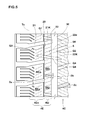
- FIG. 5 is a developed partial view showing the shoulder land region of the tread portion shown in FIG. 1 .
- FIG. 6 is a diagram for explaining the operation and effect of the axially inner and outer shoulder oblique grooves and the crown oblique grooves.
- FIG. 7(A) is a cross sectional view taken along line A-A in FIG. 1 .
- FIG. 7(B) is a cross sectional view taken along line B-B in FIG. 1 .
- pneumatic tire 1 is provided in the tread portion 2 with circumferential main grooves 3 extending circumferentially of the tire and including a pair of axially outermost shoulder circumferential main grooves 3 E.
- the tread portion 2 is axially divided into a crown land region 4 C between the shoulder circumferential main grooves 3 E, and a pair of shoulder land regions 4 E between the shoulder circumferential main grooves 3 E and the tread edges Te.
- main groove means a relatively wide groove having a width of not less than 3.0 mm.
- a groove having a width of less than 3.0 mm is called “narrow groove”.
- a groove having a width of less than 2.0 mm (inclusive of a cut having substantially no groove width) is called “sipe”.
- the crown land region 4 C is provided with crown oblique grooves 8 extending from one of the shoulder circumferential main grooves 3 E to the other, while inclining with respect to the tire axial direction.
- Each of the shoulder land regions 4 E is provided with
- the shoulder land region 4 E is axially divided into an axial inner part 4 Ei and an axially outer part 4 Eo.
- the axially inner part 4 Ei is circumferentially divided by the axially inner shoulder oblique grooves 22 into a plurality of axially inner shoulder blocks BEi.
- the axially outer part 4 Eo is circumferentially divided by the axially outer shoulder oblique grooves 21 into a plurality of axially outer shoulder blocks BEo.
- the axially outer shoulder oblique grooves 21 are inclined with respect to the tire axial direction to one direction same as that of the crown oblique grooves 8 .
- the axially inner shoulder oblique grooves 22 are inclined with respect to the tire axial direction to one direction opposite to that of the axially outer shoulder oblique grooves 21 .
- the axially inner ends 22 e of the axially inner shoulder oblique grooves 22 are terminated within the crown land region 4 C.
- the axially outer shoulder oblique grooves 21 and the axially inner shoulder oblique grooves 22 extend straight along the respective entire lengths.
- imaginary axially inward extensions 21 K of the axially outer shoulder oblique grooves 21 are shifted in the tire circumferential direction from the openings Q 1 of the axially inner shoulder oblique grooves 22 at the circumferential narrow groove 20 not to overlap with the openings Q 1 .
- imaginary axially inward extensions 22 K of the axially inner shoulder oblique grooves 22 are shifted in the tire circumferential direction from the openings Q 2 of the crown oblique grooves 8 at the shoulder circumferential main groove 3 E not to overlap with the openings Q 2
- imaginary axially outward extensions 22 K of the axially inner shoulder oblique grooves 22 are shifted in the tire circumferential direction from the openings Q 3 of the axially outer shoulder oblique grooves 21 at the circumferential narrow groove 20 not to overlap with the openings Q 3 .
- an axially inner end of the compacted snow Va in the axially outer shoulder oblique groove 21 on one side of the tire equator (on the left side in the figure) is pressed against and supported by the axial inner groove wall of the circumferential narrow groove 20 ;
- an axially end of the compacted snow Vb in the axially inner shoulder oblique groove 22 on one side of the tire equator (on the left side in the figure) is pressed against and supported by the crown land region 4 c ;
- the axially outer shoulder oblique grooves 21 are inclined oppositely to the axially inner shoulder oblique grooves 22 which are inclined oppositely to the crown oblique grooves 8 .
- the axially adjacent oblique lateral grooves are inclined oppositely to each other.
- the tread pattern rigidity becomes hard to be biased, and it becomes possible to increase the lateral grip force without largely deteriorating the wear resistance.
- the angle ⁇ a of the axially outer shoulder oblique grooves 21 with respect to the tire axial direction is preferably set in a range of 15 to 30 degrees
- the angle ⁇ b of the axially inner shoulder oblique grooves 22 with respect to the tire axial direction is preferably set in a range of 15 to 30 degrees
- the angle ⁇ c of the crown oblique grooves 8 with respect to the tire axial direction is preferably set in a range of 15 to 35 degrees.
- angles ⁇ a to ⁇ c become less than the respective lower limits, then the lateral grip force during cornering is decreased, and the effect to improve the cornering performance on snowy roads is decreased.
- angles ⁇ a to ⁇ c become more than the respective upper limits, then although the lateral grip force is increased, as the tread pattern rigidity is biased, the uneven wear resistance is liable to decrease.
- the depth D 3 of the circumferential main grooves 3 is not less than 6.5 mm, preferably not less than 7.5 mm, but not more than 13.0 mm, preferably not more than 12.5 mm.
- all of the circumferential main grooves 3 have the same depth D 3 .
- the depth D 8 of the crown oblique grooves 8 is less than the depth D 3 .
- the depth D 8 is set in a range of 60% to 80% of the depth D 3 .
- Each of the crown oblique grooves 8 may be provided with a tie bar 12 rising from the groove bottom and connecting between the circumferentially adjacent crown blocks to increase the rigidity of the crown blocks.
- the depths D 21 and D 22 of axially outer and inner shoulder oblique grooves 21 and 22 are less than the depth D 3 .
- the depths D 21 and D 22 are set in a range of the 60% to 80% of the depth D 3 .
- Each of the axially outer shoulder oblique grooves 21 may be provided with a tie bar 24 similar to the tie bar 12 .
- Each of the axially inner shoulder oblique grooves 22 may be provided with a tie bar 25 similar to the tie bar 12 .
- the depth D 20 of the circumferential narrow grooves 20 is preferably less than the depth D 3 and less than the depths D 21 and D 22 .
- the crown land region 4 C is provided with a center circumferential main groove 3 C extending circumferentially of the tire.
- the crown land region 4 C is axially divided into two parts 4 CA and 4 CA each of which is circumferentially divided into crown blocks BC in a circumferential row.
- crown oblique grooves 8 are each axially divided into two lateral groove parts 8 A and 8 A.
- the lateral groove parts 8 A of the crown oblique grooves 8 extend straight along the respective entire lengths.
- each crown oblique groove 8 is two axially outward extensions from the respective lateral groove parts 8 A.
- the center circumferential main groove 3 C is a saw-tooth like zigzag groove made up of alternate lateral groove segments 5 and longitudinal groove segments 6 .
- the lateral groove segments 5 extend substantially parallel with the tire axial direction.
- the longitudinal groove segments 6 extend at a small angle with respect to the tire circumferential direction.
- the lateral groove segments 5 are distinguished from the longitudinal groove segments 6 as shown in FIG. 2 by dark and light gray.
- the zigzag amplitude center line of the center circumferential main groove 3 C coincides with the tire equator Co. But, it may be possible that the zigzag amplitude center line does not coincide with the tire equator Co, or the center circumferential main groove 3 C is separated from the tire equator Co.
- the opposite groove walls 5 S of the lateral groove segment 5 extend at an angle ⁇ of not more than 5 degrees with respect to the tire axial direction.
- the opposite groove walls 6 S of the longitudinal groove segment 6 (hereinafter, the “longitudinal groove walls” 6 S) extend at an angle ⁇ of not less than 60 degrees with respect to the tire axial direction.
- One lateral groove segment 5 and one longitudinal groove segment 6 as one unit PC are repeated circumferentially of the tire.
- each of the lateral groove segments 5 are connected to the axially inner ends of two of the lateral groove parts 8 A disposed on both sides thereof.
- the crown land region 4 C is such a region where the ground contacting pressure is relatively high and whose ground contacting length in the tire circumferential direction is relatively long. Accordingly, its effect on the snow performance is large.
- the saw-tooth like center circumferential main groove 3 C and the crown oblique grooves 8 are disposed in this region in order to maximally derive the undermentioned effects, and thereby to further improve the snow performance.
- the center circumferential main groove 3 C can most effectively contribute to the traction performance in relation to the zigzag amplitude.
- both ends of the lateral groove segment 5 are connected to the lateral groove parts 8 A, the compression force F is transmitted to snow in the lateral groove parts 8 A through the snow in the lateral groove segment 5 .
- the snow in the longitudinal groove segment 6 , the snow in the lateral groove segment 5 , and the snow in the lateral groove parts 8 A are compacted and form a substantially T-shaped hard compacted snow together.
- Such compacted snow therefore can exert large sharing force in both of the tire circumferential direction and the tire axial direction, and the grip performance on snowy roads is improved.
- the length L 1 in the tire axial direction of the lateral groove walls 5 S as shown in FIG. 2 is in a range of from 2% to 10% of the tread width TW. If the length L 1 is less than 2% of the tread width TW, the lateral groove wall 5 S can not stop the snow in the longitudinal groove segment 6 , and the compression force F is reduced or not generated, and accordingly, the hard compacted snow can not be formed. Even if the length L 1 is increased over 10% of the tread width TW, a further increase in the sharing force of the compacted snow can not be obtained.
- the rigidity of the crown blocks BC is decreased disadvantageously for the wear resistance and the uneven wear resistance because the zigzag amplitude increases with the increase in the length L 1 , and as a result, a maximum WB 1 of the axial width of the crown block BC is increased and a minimum WB 2 thereof is decreased. Namely, the rigidity of the crown block BC becomes more uneven. Thus, the wear resistance and the uneven wear resistance are deteriorated.
- the length L 1 is not less than 4%, but not more than 8% of the tread width TW. From a point of view of the wear resistance and the uneven wear resistance, it is desirable that the angle ⁇ of the longitudinal groove walls 6 S is not less than 75 degrees.
- the length L 1 is preferably not less than the width W 6 in the tire axial direction of the longitudinal groove segment 6 .
- the ratio W 2 /W 1 of the groove width W 2 of the lateral groove segment 5 to the groove width W 1 of the longitudinal groove segment 6 is set in a range of from 0.8 to 2.0.
- the groove width W 1 is the distance between the lateral groove walls 5 S of the lateral groove segment 5 measured perpendicularly to the groove's length direction.
- the groove width W 2 is the distance between the longitudinal groove walls 6 S of the longitudinal groove segment 6 measured perpendicularly to the groove's length direction.
- the center circumferential main groove 3 C may be provided with a chamfer 11 in each external corner P formed between the lateral groove wall 5 S and the longitudinal groove wall 6 S.
- the length L 1 of the lateral groove wall 5 S is defined by the length of the lateral groove wall 5 S excluding the chamfer 11 .
- the lateral groove parts 8 A are inclined with respect to the tire axial direction to one direction same as that of the longitudinal groove segments 6 .
- the lateral groove parts 8 A and the longitudinal groove segments 6 in this example are inclined upward to the right.
- the crown blocks BC are provided with sipes 10 .
- the sipes 10 are inclined with respect to the tire axial direction to one direction opposite to that of the lateral groove parts 8 A.
- the sipes 10 in this example are inclined downward to the right whereas the lateral groove parts 8 A are inclined upward to the right.
- the tire were tested for the snow performance and wear resistance as follows.
- test tires were mounted on all of the four wheels of a medium-sized van (Engine displacement 2800 cc, front tire pressure 390 kPa, rear tire pressure 350 kPa, load 50% of maximum load), and a test driver evaluated the lateral grip force during running on a snow covered road surface of a tire test course.
- the results are indicated in Table 1 by an index based on Comparative example tire Ref.1 being 100, wherein the larger the index number, the higher the lateral grip force, namely, the better the cornering performance on snow.
- the test driver evaluated the steering stability during running on a wet road surface of the tire test course.
- the results are indicated in Table 2 by an index based on Comparative example tire Ref.A1 being 100, wherein the larger the index number, the better the wet performance.
Landscapes
- Engineering & Computer Science (AREA)
- Mechanical Engineering (AREA)
- Tires In General (AREA)
Abstract
Description
Such compacted snow provides a sharing force and helps to improve the snow performance of the tire.
But, in the case of the disclosed tire, the crisscross compacted snow is difficult to provide a large sharing force against a lateral force generated for example during cornering for the following reasons.
Since the axially outer open end of the axially outer crown lateral groove faces the axially inner open end of the shoulder lateral groove, the axially outer end of the compacted snow in the axially outer crown lateral groove and the axially inner end of the compacted snow in the shoulder lateral groove are not supported by groove walls and they support each other.
Therefore, although the sharing force in the tire axial direction, of the compacted snow in the shoulder circumferential main groove makes a contribution to the sharing force against the lateral force during cornering, the sharing force in the tire axial direction, of the compacted snow in the axially outer crown lateral groove, and the sharing force in the tire axial direction, of the compacted snow in the shoulder lateral groove can not make a contribution thereto.
As a result, it is difficult for the compacted snow to generate large lateral grip force, and the tire can not exert sufficient cornering performance on snow covered roads.
Thus, there is room for improvement in the cornering performance on snow covered roads.
imaginary axially
Furthermore, imaginary axially
Therefore, during cornering on snowy road, for example as shown in
Even if the length L1 is increased over 10% of the tread width TW, a further increase in the sharing force of the compacted snow can not be obtained.
In addition, the rigidity of the crown blocks BC is decreased disadvantageously for the wear resistance and the uneven wear resistance because the zigzag amplitude increases with the increase in the length L1, and as a result, a maximum WB1 of the axial width of the crown block BC is increased and a minimum WB2 thereof is decreased. Namely, the rigidity of the crown block BC becomes more uneven. Thus, the wear resistance and the uneven wear resistance are deteriorated.
In this example, the shoulder circumferential
Thereby, the drainage and the self ejection of snow are improved. Further, the straight running stability is improved during running on snowy roads.
| TABLE 1 | ||||||||||||
| Tire | Ref. 1 | Ref. 2 | Ref. 3 | Ref. 4 | Ex. 1 | Ex. 2 | Ex. 3 | Ex. 4 | Ex. 5 | Ex. 6 | Ex. 7 | Ex. 8 |
| axially outer shoulder oblique grooves | ||||||||||||
| angle θa (deg.) *1 | +15 | +25 | +25 | +25 | +5 | +15 | +25 | +30 | +35 | +25 | +25 | +25 |
| axially inner shoulder oblique grooves | ||||||||||||
| angle θb (deg.) *1 | +15 | −25 | −25 | −25 | −25 | −25 | −25 | −25 | −25 | −5 | −15 | −25 |
| crown oblique grooves | ||||||||||||
| angle θc (deg.) *1 | +15 | +30 | +30 | +30 | +30 | +30 | +30 | +30 | +30 | +30 | +30 | +30 |
| (O)verlap or (N)ot | ||||||||||||
| imaginary extension 21K & opening Q1 | N | O | N | N | N | N | N | N | N | N | N | N |
| imaginary extension 22K & opening Q3 | N | N | O | N | N | N | N | N | N | N | N | N |
| imaginary extension 8K & opening Q4 | N | N | N | O | N | N | N | N | N | N | N | N |
| center sipes' inclining direction *2 | opposite |
| center circumferential main groove | ||||||||||||
| lateral groove segment angle α (deg.) | 0 | 0 | 0 | 0 | 0 | 0 | 0 | 0 | 0 | 0 | 0 | 0 |
| longitudinal groove segment angle β (deg.) | 78 | 78 | 78 | 78 | 78 | 78 | 78 | 78 | 78 | 78 | 78 | 78 |
| cornering performance on snow | 100 | 95 | 98 | 95 | 110 | 120 | 130 | 120 | 120 | 110 | 120 | 130 |
| wear resistance | 100 | 100 | 100 | 100 | 100 | 100 | 100 | 100 | 90 | 100 | 100 | 100 |
| Total | 200 | 195 | 198 | 195 | 210 | 220 | 230 | 220 | 210 | 210 | 220 | 230 |
| Tire | Ex. 9 | Ex. 10 | Ex. 11 | Ex. 12 | Ex. 13 | Ex. 14 | Ex. 15 | Ex. 16 | Ex. 17 | Ex. 18 | Ex. 19 |
| axially outer shoulder oblique grooves | |||||||||||
| angle θa (deg.) *1 | +25 | +25 | +25 | +25 | +25 | +25 | +25 | +25 | +25 | +25 | +25 |
| axially inner shoulder oblique grooves | |||||||||||
| angle θb (deg.) *1 | −30 | −35 | −25 | −25 | −25 | −25 | −25 | −25 | −25 | −25 | −25 |
| crown oblique grooves | |||||||||||
| angle θc (deg.) *1 | +30 | +30 | +5 | +15 | +25 | +30 | +35 | +25 | +30 | +30 | +30 |
| (O)verlap or (N)ot | |||||||||||
| imaginary extension 21K & opening Q1 | N | N | N | N | N | N | N | N | N | N | N |
| imaginary extension 22K & opening Q3 | N | N | N | N | N | N | N | N | N | N | N |
| imaginary extension 8K & opening Q4 | N | N | N | N | N | N | N | N | N | N | N |
| center sipes' inclining direction *2 | opposite | same | opposite | opposite |
| center circumferential main groove | |||||||||||
| lateral groove segment angle α (deg.) | 0 | 0 | 0 | 0 | 0 | 0 | 0 | 0 | 0 | 5 | 0 |
| longitudinal groove segment angle β (deg.) | 78 | 78 | 78 | 78 | 78 | 78 | 78 | 78 | 78 | 78 | 60 |
| cornering performance on snow | 120 | 120 | 110 | 120 | 130 | 125 | 120 | 120 | 125 | 125 | 120 |
| wear resistance | 100 | 90 | 100 | 100 | 100 | 100 | 100 | 90 | 100 | 100 | 100 |
| Total | 220 | 210 | 210 | 220 | 230 | 225 | 220 | 210 | 225 | 225 | 220 |
| *1 + (plus sign): inclined upward to the right | |||||||||||
| − (minus sign): inclined downward to the right | |||||||||||
| *2 “opposite”: inclined to the opposite direction to the crown oblique grooves | |||||||||||
| “same”: inclined to the same direction as the crown oblique grooves | |||||||||||
| TABLE 2 | ||||||||
| Tire | Ref. A1 | Ex. A1 | Ex. A2 | Ex. A3 | Ref. A2 | Ex. A4 | Ref. A3 | Ex. A5 |
| center circumferential main groove | ||||||||
| lateral groove segment angle α (deg.) | 0 | 0 | 0 | 0 | 0 | 5 | 10 | 0 |
| longitudinal groove segment angle β (deg.) | 78 | 78 | 78 | 78 | 78 | 78 | 78 | 78 |
| length ratio L1/TW(%) | 1 | 2 | 4 | 10 | 15 | 4 | 4 | 4 |
| groove width ratio W2/ |
1 | 1 | 1 | 1 | 1 | 1 | 1 | 0.5 |
| inclination | ||||||||
| crown oblique grooves and longitudinal groove segments | same | same | same | same | same | same | same | same |
| crown oblique grooves and sipes | opposite | opposite | opposite | opposite | opposite | opposite | opposite | opposite |
| crown oblique groove angle θc (deg.) | 30 | 30 | 30 | 30 | 30 | 30 | 30 | 30 |
| snow performance | 100 | 108 | 115 | 120 | 110 | 110 | 102 | 108 |
| wet performance | 100 | 100 | 98 | 95 | 86 | 100 | 95 | 94 |
| total | 200 | 208 | 213 | 215 | 196 | 210 | 197 | 202 |
| Tire | Ex. A6 | Ex. A7 | Ex. A8 | Ex. A9 | Ex. A10 | Ex. A11 | Ex. A12 | Ex. A13 |
| center circumferential main groove | ||||||||
| lateral groove segment angle α (deg.) | 0 | 0 | 0 | 0 | 0 | 0 | 0 | 0 |
| longitudinal groove segment angle β (deg.) | 78 | 78 | 78 | 78 | 60 | 78 | 78 | 78 |
| length ratio L1/TW(%) | 4 | 4 | 4 | 4 | 4 | 4 | 4 | 4 |
| groove width ratio W2/W1 | 0.8 | 2 | 2.5 | 1 | 1 | 1 | 1 | 1 |
| inclination | ||||||||
| crown oblique grooves and longitudinal groove segments | same | same | same | opposite | same | same | same | same |
| crown oblique grooves and sipes | opposite | opposite | opposite | opposite | same | opposite | opposite | opposite |
| crown oblique groove angle θc (deg.) | 30 | 30 | 30 | 30 | 30 | 30 | 15 | 35 |
| snow performance | 110 | 110 | 105 | 115 | 112 | 110 | 115 | 110 |
| wet performance | 98 | 102 | 105 | 95 | 98 | 98 | 92 | 98 |
| total | 208 | 212 | 210 | 210 | 210 | 208 | 207 | 208 |
-
- 1 pneumatic tire
- 2 tread portion
- 3C center circumferential main groove
- 3E shoulder circumferential main groove
- 4C crown land region
- 4E shoulder land region
- 5 lateral groove segment
- 5S lateral groove wall
- 6 longitudinal groove segment
- 6S longitudinal groove wall
- 8 crown oblique groove
- 8K imaginary extension
- 10 sipe
- 20 circumferential narrow groove
- 21 axially outer shoulder oblique groove
- 22 e inner end
- 22 axially inner shoulder oblique groove
- 21K imaginary extension
- 22K imaginary extension
- BC crown block
- Co tire equator
- Q1, Q2, Q3, Q4 opening
Claims (15)
Applications Claiming Priority (4)
| Application Number | Priority Date | Filing Date | Title |
|---|---|---|---|
| JP2014-226298 | 2014-11-06 | ||
| JP2014226298A JP6235985B2 (en) | 2014-11-06 | 2014-11-06 | Pneumatic tire |
| JP2014-235823 | 2014-11-20 | ||
| JP2014235823A JP6130822B2 (en) | 2014-11-20 | 2014-11-20 | Pneumatic tire |
Publications (2)
| Publication Number | Publication Date |
|---|---|
| US20160129732A1 US20160129732A1 (en) | 2016-05-12 |
| US10071601B2 true US10071601B2 (en) | 2018-09-11 |
Family
ID=54360065
Family Applications (1)
| Application Number | Title | Priority Date | Filing Date |
|---|---|---|---|
| US14/920,372 Active 2036-05-13 US10071601B2 (en) | 2014-11-06 | 2015-10-22 | Pneumatic tire having a zigzag center main groove and shoulder oblique grooves |
Country Status (3)
| Country | Link |
|---|---|
| US (1) | US10071601B2 (en) |
| EP (1) | EP3017963B1 (en) |
| CN (1) | CN105584298B (en) |
Families Citing this family (6)
| Publication number | Priority date | Publication date | Assignee | Title |
|---|---|---|---|---|
| JP6772599B2 (en) * | 2016-07-01 | 2020-10-21 | 住友ゴム工業株式会社 | Pneumatic tires |
| CN107685600B (en) * | 2016-08-03 | 2020-09-08 | 横滨橡胶株式会社 | Pneumatic tire |
| EP3378678B1 (en) * | 2017-03-24 | 2021-01-20 | Sumitomo Rubber Industries, Ltd. | Tire |
| JP6904029B2 (en) * | 2017-04-11 | 2021-07-14 | 住友ゴム工業株式会社 | tire |
| JP7056333B2 (en) * | 2018-04-06 | 2022-04-19 | 住友ゴム工業株式会社 | tire |
| JP7459675B2 (en) * | 2020-06-16 | 2024-04-02 | 住友ゴム工業株式会社 | tire |
Citations (13)
| Publication number | Priority date | Publication date | Assignee | Title |
|---|---|---|---|---|
| US4461334A (en) * | 1982-07-21 | 1984-07-24 | Bridgestone Tire Company Limited | Heavy duty pneumatic tires |
| US5343914A (en) * | 1989-10-02 | 1994-09-06 | Sumitomo Rubber Industries Limited | All season pneumatic tire |
| JPH0958220A (en) * | 1995-08-29 | 1997-03-04 | Bridgestone Corp | Pneumatic tire with block pattern |
| US20030192634A1 (en) | 2001-08-22 | 2003-10-16 | Hidehiko Hino | Tire used in winter |
| EP1707405A1 (en) | 2004-01-13 | 2006-10-04 | Bridgestone Corporation | Pneumatic tire |
| JP2007118704A (en) | 2005-10-26 | 2007-05-17 | Bridgestone Corp | Pneumatic tire |
| JP2009190677A (en) | 2008-02-18 | 2009-08-27 | Sumitomo Rubber Ind Ltd | Pneumatic tire |
| US20110259494A1 (en) * | 2010-04-27 | 2011-10-27 | Keizo Shibano | Heavy duty tire |
| WO2013080944A1 (en) * | 2011-11-29 | 2013-06-06 | 住友ゴム工業株式会社 | Heavy duty tire |
| US20130192731A1 (en) * | 2012-01-26 | 2013-08-01 | Sumitomo Rubber Industries, Ltd. | Pneumatic tire |
| JP2013189128A (en) | 2012-03-14 | 2013-09-26 | Sumitomo Rubber Ind Ltd | Pneumatic tire |
| EP2821256A1 (en) | 2013-07-03 | 2015-01-07 | Sumitomo Rubber Industries, Ltd. | Pneumatic tire |
| US20150251500A1 (en) * | 2012-11-19 | 2015-09-10 | Continental Reifen Deutschland Gmbh | Pneumatic vehicle tire |
-
2015
- 2015-10-22 EP EP15191054.4A patent/EP3017963B1/en active Active
- 2015-10-22 US US14/920,372 patent/US10071601B2/en active Active
- 2015-11-05 CN CN201510745626.XA patent/CN105584298B/en active Active
Patent Citations (15)
| Publication number | Priority date | Publication date | Assignee | Title |
|---|---|---|---|---|
| US4461334A (en) * | 1982-07-21 | 1984-07-24 | Bridgestone Tire Company Limited | Heavy duty pneumatic tires |
| US5343914A (en) * | 1989-10-02 | 1994-09-06 | Sumitomo Rubber Industries Limited | All season pneumatic tire |
| JPH0958220A (en) * | 1995-08-29 | 1997-03-04 | Bridgestone Corp | Pneumatic tire with block pattern |
| US20030192634A1 (en) | 2001-08-22 | 2003-10-16 | Hidehiko Hino | Tire used in winter |
| US7137424B2 (en) * | 2001-08-22 | 2006-11-21 | Sumitomo Rubber Industries, Ltd. | Tire used in winter having pair of rib portions and central vertical groove with saw-tooth shape |
| EP1707405A1 (en) | 2004-01-13 | 2006-10-04 | Bridgestone Corporation | Pneumatic tire |
| JP2007118704A (en) | 2005-10-26 | 2007-05-17 | Bridgestone Corp | Pneumatic tire |
| JP2009190677A (en) | 2008-02-18 | 2009-08-27 | Sumitomo Rubber Ind Ltd | Pneumatic tire |
| US20110259494A1 (en) * | 2010-04-27 | 2011-10-27 | Keizo Shibano | Heavy duty tire |
| WO2013080944A1 (en) * | 2011-11-29 | 2013-06-06 | 住友ゴム工業株式会社 | Heavy duty tire |
| US20140332133A1 (en) * | 2011-11-29 | 2014-11-13 | Sumitomo Rubber Industries, Ltd. | Heavy duty tire |
| US20130192731A1 (en) * | 2012-01-26 | 2013-08-01 | Sumitomo Rubber Industries, Ltd. | Pneumatic tire |
| JP2013189128A (en) | 2012-03-14 | 2013-09-26 | Sumitomo Rubber Ind Ltd | Pneumatic tire |
| US20150251500A1 (en) * | 2012-11-19 | 2015-09-10 | Continental Reifen Deutschland Gmbh | Pneumatic vehicle tire |
| EP2821256A1 (en) | 2013-07-03 | 2015-01-07 | Sumitomo Rubber Industries, Ltd. | Pneumatic tire |
Non-Patent Citations (2)
| Title |
|---|
| Extended European Search Report, dated Mar. 30, 2016, for European Application No. 15191054.4. |
| Suretsutohoo Aaron, JP 09058220, Mar. 4, 1997, machine translation. * |
Also Published As
| Publication number | Publication date |
|---|---|
| EP3017963A1 (en) | 2016-05-11 |
| US20160129732A1 (en) | 2016-05-12 |
| EP3017963B1 (en) | 2019-05-29 |
| CN105584298A (en) | 2016-05-18 |
| CN105584298B (en) | 2019-10-15 |
Similar Documents
| Publication | Publication Date | Title |
|---|---|---|
| US10266012B2 (en) | Pneumatic tire | |
| US9434215B2 (en) | Pneumatic tire | |
| US10391819B2 (en) | Pneumatic tire | |
| US10105993B2 (en) | Pneumatic tire | |
| US10391821B2 (en) | Pneumatic tire | |
| US10322608B2 (en) | Tire | |
| US10093134B2 (en) | Pneumatic tire | |
| US10703145B2 (en) | Pneumatic tire | |
| US10363780B2 (en) | Pneumatic tire | |
| US10792957B2 (en) | Pneumatic tire | |
| US9757991B2 (en) | Pneumatic tire | |
| US10124628B2 (en) | Heavy duty pneumatic tire | |
| US20160288580A1 (en) | Pneumatic tire | |
| US11179972B2 (en) | Tire | |
| US10864776B2 (en) | Pneumatic tire | |
| US20160089939A1 (en) | Pneumatic tire | |
| US10071601B2 (en) | Pneumatic tire having a zigzag center main groove and shoulder oblique grooves | |
| CN109927488A (en) | tire | |
| US11046122B2 (en) | Tire | |
| US10596855B2 (en) | Tire | |
| US10744822B2 (en) | Heavy duty tire | |
| US10442248B2 (en) | Tire | |
| US11772428B2 (en) | Tire | |
| US10821780B2 (en) | Tire | |
| US10232669B2 (en) | Heavy duty pneumatic tire |
Legal Events
| Date | Code | Title | Description |
|---|---|---|---|
| AS | Assignment |
Owner name: SUMITOMO RUBBER INDUSTRIES, LTD., JAPAN Free format text: ASSIGNMENT OF ASSIGNORS INTEREST;ASSIGNORS:KUROSAWA, DAI;SATO, TAKUYA;REEL/FRAME:036864/0428 Effective date: 20151007 |
|
| STCF | Information on status: patent grant |
Free format text: PATENTED CASE |
|
| MAFP | Maintenance fee payment |
Free format text: PAYMENT OF MAINTENANCE FEE, 4TH YEAR, LARGE ENTITY (ORIGINAL EVENT CODE: M1551); ENTITY STATUS OF PATENT OWNER: LARGE ENTITY Year of fee payment: 4 |
|
| MAFP | Maintenance fee payment |
Free format text: PAYMENT OF MAINTENANCE FEE, 8TH YEAR, LARGE ENTITY (ORIGINAL EVENT CODE: M1552); ENTITY STATUS OF PATENT OWNER: LARGE ENTITY Year of fee payment: 8 |