US10071545B2 - Systems for additively manufacturing composite parts - Google Patents
Systems for additively manufacturing composite parts Download PDFInfo
- Publication number
- US10071545B2 US10071545B2 US15/087,882 US201615087882A US10071545B2 US 10071545 B2 US10071545 B2 US 10071545B2 US 201615087882 A US201615087882 A US 201615087882A US 10071545 B2 US10071545 B2 US 10071545B2
- Authority
- US
- United States
- Prior art keywords
- housing
- flexible line
- continuous flexible
- nozzle
- human user
- Prior art date
- Legal status (The legal status is an assumption and is not a legal conclusion. Google has not performed a legal analysis and makes no representation as to the accuracy of the status listed.)
- Active, expires
Links
Images


Classifications
-
- B—PERFORMING OPERATIONS; TRANSPORTING
- B33—ADDITIVE MANUFACTURING TECHNOLOGY
- B33Y—ADDITIVE MANUFACTURING, i.e. MANUFACTURING OF THREE-DIMENSIONAL [3D] OBJECTS BY ADDITIVE DEPOSITION, ADDITIVE AGGLOMERATION OR ADDITIVE LAYERING, e.g. BY 3D PRINTING, STEREOLITHOGRAPHY OR SELECTIVE LASER SINTERING
- B33Y70/00—Materials specially adapted for additive manufacturing
-
- B—PERFORMING OPERATIONS; TRANSPORTING
- B05—SPRAYING OR ATOMISING IN GENERAL; APPLYING FLUENT MATERIALS TO SURFACES, IN GENERAL
- B05D—PROCESSES FOR APPLYING FLUENT MATERIALS TO SURFACES, IN GENERAL
- B05D1/00—Processes for applying liquids or other fluent materials
- B05D1/26—Processes for applying liquids or other fluent materials performed by applying the liquid or other fluent material from an outlet device in contact with, or almost in contact with, the surface
- B05D1/265—Extrusion coatings
-
- B—PERFORMING OPERATIONS; TRANSPORTING
- B05—SPRAYING OR ATOMISING IN GENERAL; APPLYING FLUENT MATERIALS TO SURFACES, IN GENERAL
- B05D—PROCESSES FOR APPLYING FLUENT MATERIALS TO SURFACES, IN GENERAL
- B05D1/00—Processes for applying liquids or other fluent materials
- B05D1/34—Applying different liquids or other fluent materials simultaneously
-
- B—PERFORMING OPERATIONS; TRANSPORTING
- B05—SPRAYING OR ATOMISING IN GENERAL; APPLYING FLUENT MATERIALS TO SURFACES, IN GENERAL
- B05D—PROCESSES FOR APPLYING FLUENT MATERIALS TO SURFACES, IN GENERAL
- B05D3/00—Pretreatment of surfaces to which liquids or other fluent materials are to be applied; After-treatment of applied coatings, e.g. intermediate treating of an applied coating preparatory to subsequent applications of liquids or other fluent materials
- B05D3/06—Pretreatment of surfaces to which liquids or other fluent materials are to be applied; After-treatment of applied coatings, e.g. intermediate treating of an applied coating preparatory to subsequent applications of liquids or other fluent materials by exposure to radiation
- B05D3/061—Pretreatment of surfaces to which liquids or other fluent materials are to be applied; After-treatment of applied coatings, e.g. intermediate treating of an applied coating preparatory to subsequent applications of liquids or other fluent materials by exposure to radiation using U.V.
- B05D3/065—After-treatment
- B05D3/067—Curing or cross-linking the coating
-
- B—PERFORMING OPERATIONS; TRANSPORTING
- B05—SPRAYING OR ATOMISING IN GENERAL; APPLYING FLUENT MATERIALS TO SURFACES, IN GENERAL
- B05D—PROCESSES FOR APPLYING FLUENT MATERIALS TO SURFACES, IN GENERAL
- B05D3/00—Pretreatment of surfaces to which liquids or other fluent materials are to be applied; After-treatment of applied coatings, e.g. intermediate treating of an applied coating preparatory to subsequent applications of liquids or other fluent materials
- B05D3/06—Pretreatment of surfaces to which liquids or other fluent materials are to be applied; After-treatment of applied coatings, e.g. intermediate treating of an applied coating preparatory to subsequent applications of liquids or other fluent materials by exposure to radiation
- B05D3/068—Pretreatment of surfaces to which liquids or other fluent materials are to be applied; After-treatment of applied coatings, e.g. intermediate treating of an applied coating preparatory to subsequent applications of liquids or other fluent materials by exposure to radiation using ionising radiations (gamma, X, electrons)
-
- B—PERFORMING OPERATIONS; TRANSPORTING
- B05—SPRAYING OR ATOMISING IN GENERAL; APPLYING FLUENT MATERIALS TO SURFACES, IN GENERAL
- B05D—PROCESSES FOR APPLYING FLUENT MATERIALS TO SURFACES, IN GENERAL
- B05D3/00—Pretreatment of surfaces to which liquids or other fluent materials are to be applied; After-treatment of applied coatings, e.g. intermediate treating of an applied coating preparatory to subsequent applications of liquids or other fluent materials
- B05D3/12—Pretreatment of surfaces to which liquids or other fluent materials are to be applied; After-treatment of applied coatings, e.g. intermediate treating of an applied coating preparatory to subsequent applications of liquids or other fluent materials by mechanical means
-
- B—PERFORMING OPERATIONS; TRANSPORTING
- B29—WORKING OF PLASTICS; WORKING OF SUBSTANCES IN A PLASTIC STATE IN GENERAL
- B29B—PREPARATION OR PRETREATMENT OF THE MATERIAL TO BE SHAPED; MAKING GRANULES OR PREFORMS; RECOVERY OF PLASTICS OR OTHER CONSTITUENTS OF WASTE MATERIAL CONTAINING PLASTICS
- B29B11/00—Making preforms
- B29B11/14—Making preforms characterised by structure or composition
- B29B11/16—Making preforms characterised by structure or composition comprising fillers or reinforcement
-
- B—PERFORMING OPERATIONS; TRANSPORTING
- B29—WORKING OF PLASTICS; WORKING OF SUBSTANCES IN A PLASTIC STATE IN GENERAL
- B29C—SHAPING OR JOINING OF PLASTICS; SHAPING OF MATERIAL IN A PLASTIC STATE, NOT OTHERWISE PROVIDED FOR; AFTER-TREATMENT OF THE SHAPED PRODUCTS, e.g. REPAIRING
- B29C35/00—Heating, cooling or curing, e.g. crosslinking or vulcanising; Apparatus therefor
- B29C35/16—Cooling
-
- B29C47/0002—
-
- B—PERFORMING OPERATIONS; TRANSPORTING
- B29—WORKING OF PLASTICS; WORKING OF SUBSTANCES IN A PLASTIC STATE IN GENERAL
- B29C—SHAPING OR JOINING OF PLASTICS; SHAPING OF MATERIAL IN A PLASTIC STATE, NOT OTHERWISE PROVIDED FOR; AFTER-TREATMENT OF THE SHAPED PRODUCTS, e.g. REPAIRING
- B29C48/00—Extrusion moulding, i.e. expressing the moulding material through a die or nozzle which imparts the desired form; Apparatus therefor
- B29C48/02—Small extruding apparatus, e.g. handheld, toy or laboratory extruders
-
- B—PERFORMING OPERATIONS; TRANSPORTING
- B29—WORKING OF PLASTICS; WORKING OF SUBSTANCES IN A PLASTIC STATE IN GENERAL
- B29C—SHAPING OR JOINING OF PLASTICS; SHAPING OF MATERIAL IN A PLASTIC STATE, NOT OTHERWISE PROVIDED FOR; AFTER-TREATMENT OF THE SHAPED PRODUCTS, e.g. REPAIRING
- B29C64/00—Additive manufacturing, i.e. manufacturing of three-dimensional [3D] objects by additive deposition, additive agglomeration or additive layering, e.g. by 3D printing, stereolithography or selective laser sintering
- B29C64/10—Processes of additive manufacturing
- B29C64/106—Processes of additive manufacturing using only liquids or viscous materials, e.g. depositing a continuous bead of viscous material
- B29C64/118—Processes of additive manufacturing using only liquids or viscous materials, e.g. depositing a continuous bead of viscous material using filamentary material being melted, e.g. fused deposition modelling [FDM]
-
- B—PERFORMING OPERATIONS; TRANSPORTING
- B29—WORKING OF PLASTICS; WORKING OF SUBSTANCES IN A PLASTIC STATE IN GENERAL
- B29C—SHAPING OR JOINING OF PLASTICS; SHAPING OF MATERIAL IN A PLASTIC STATE, NOT OTHERWISE PROVIDED FOR; AFTER-TREATMENT OF THE SHAPED PRODUCTS, e.g. REPAIRING
- B29C64/00—Additive manufacturing, i.e. manufacturing of three-dimensional [3D] objects by additive deposition, additive agglomeration or additive layering, e.g. by 3D printing, stereolithography or selective laser sintering
- B29C64/10—Processes of additive manufacturing
- B29C64/106—Processes of additive manufacturing using only liquids or viscous materials, e.g. depositing a continuous bead of viscous material
- B29C64/124—Processes of additive manufacturing using only liquids or viscous materials, e.g. depositing a continuous bead of viscous material using layers of liquid which are selectively solidified
- B29C64/129—Processes of additive manufacturing using only liquids or viscous materials, e.g. depositing a continuous bead of viscous material using layers of liquid which are selectively solidified characterised by the energy source therefor, e.g. by global irradiation combined with a mask
- B29C64/135—Processes of additive manufacturing using only liquids or viscous materials, e.g. depositing a continuous bead of viscous material using layers of liquid which are selectively solidified characterised by the energy source therefor, e.g. by global irradiation combined with a mask the energy source being concentrated, e.g. scanning lasers or focused light sources
-
- B—PERFORMING OPERATIONS; TRANSPORTING
- B29—WORKING OF PLASTICS; WORKING OF SUBSTANCES IN A PLASTIC STATE IN GENERAL
- B29C—SHAPING OR JOINING OF PLASTICS; SHAPING OF MATERIAL IN A PLASTIC STATE, NOT OTHERWISE PROVIDED FOR; AFTER-TREATMENT OF THE SHAPED PRODUCTS, e.g. REPAIRING
- B29C64/00—Additive manufacturing, i.e. manufacturing of three-dimensional [3D] objects by additive deposition, additive agglomeration or additive layering, e.g. by 3D printing, stereolithography or selective laser sintering
- B29C64/10—Processes of additive manufacturing
- B29C64/165—Processes of additive manufacturing using a combination of solid and fluid materials, e.g. a powder selectively bound by a liquid binder, catalyst, inhibitor or energy absorber
-
- B—PERFORMING OPERATIONS; TRANSPORTING
- B29—WORKING OF PLASTICS; WORKING OF SUBSTANCES IN A PLASTIC STATE IN GENERAL
- B29C—SHAPING OR JOINING OF PLASTICS; SHAPING OF MATERIAL IN A PLASTIC STATE, NOT OTHERWISE PROVIDED FOR; AFTER-TREATMENT OF THE SHAPED PRODUCTS, e.g. REPAIRING
- B29C64/00—Additive manufacturing, i.e. manufacturing of three-dimensional [3D] objects by additive deposition, additive agglomeration or additive layering, e.g. by 3D printing, stereolithography or selective laser sintering
- B29C64/20—Apparatus for additive manufacturing; Details thereof or accessories therefor
- B29C64/205—Means for applying layers
- B29C64/209—Heads; Nozzles
-
- B—PERFORMING OPERATIONS; TRANSPORTING
- B29—WORKING OF PLASTICS; WORKING OF SUBSTANCES IN A PLASTIC STATE IN GENERAL
- B29C—SHAPING OR JOINING OF PLASTICS; SHAPING OF MATERIAL IN A PLASTIC STATE, NOT OTHERWISE PROVIDED FOR; AFTER-TREATMENT OF THE SHAPED PRODUCTS, e.g. REPAIRING
- B29C64/00—Additive manufacturing, i.e. manufacturing of three-dimensional [3D] objects by additive deposition, additive agglomeration or additive layering, e.g. by 3D printing, stereolithography or selective laser sintering
- B29C64/30—Auxiliary operations or equipment
- B29C64/307—Handling of material to be used in additive manufacturing
- B29C64/314—Preparation
-
- B—PERFORMING OPERATIONS; TRANSPORTING
- B29—WORKING OF PLASTICS; WORKING OF SUBSTANCES IN A PLASTIC STATE IN GENERAL
- B29C—SHAPING OR JOINING OF PLASTICS; SHAPING OF MATERIAL IN A PLASTIC STATE, NOT OTHERWISE PROVIDED FOR; AFTER-TREATMENT OF THE SHAPED PRODUCTS, e.g. REPAIRING
- B29C64/00—Additive manufacturing, i.e. manufacturing of three-dimensional [3D] objects by additive deposition, additive agglomeration or additive layering, e.g. by 3D printing, stereolithography or selective laser sintering
- B29C64/30—Auxiliary operations or equipment
- B29C64/307—Handling of material to be used in additive manufacturing
- B29C64/321—Feeding
-
- B—PERFORMING OPERATIONS; TRANSPORTING
- B29—WORKING OF PLASTICS; WORKING OF SUBSTANCES IN A PLASTIC STATE IN GENERAL
- B29C—SHAPING OR JOINING OF PLASTICS; SHAPING OF MATERIAL IN A PLASTIC STATE, NOT OTHERWISE PROVIDED FOR; AFTER-TREATMENT OF THE SHAPED PRODUCTS, e.g. REPAIRING
- B29C64/00—Additive manufacturing, i.e. manufacturing of three-dimensional [3D] objects by additive deposition, additive agglomeration or additive layering, e.g. by 3D printing, stereolithography or selective laser sintering
- B29C64/30—Auxiliary operations or equipment
- B29C64/386—Data acquisition or data processing for additive manufacturing
- B29C64/393—Data acquisition or data processing for additive manufacturing for controlling or regulating additive manufacturing processes
-
- B—PERFORMING OPERATIONS; TRANSPORTING
- B29—WORKING OF PLASTICS; WORKING OF SUBSTANCES IN A PLASTIC STATE IN GENERAL
- B29C—SHAPING OR JOINING OF PLASTICS; SHAPING OF MATERIAL IN A PLASTIC STATE, NOT OTHERWISE PROVIDED FOR; AFTER-TREATMENT OF THE SHAPED PRODUCTS, e.g. REPAIRING
- B29C64/00—Additive manufacturing, i.e. manufacturing of three-dimensional [3D] objects by additive deposition, additive agglomeration or additive layering, e.g. by 3D printing, stereolithography or selective laser sintering
- B29C64/40—Structures for supporting 3D objects during manufacture and intended to be sacrificed after completion thereof
-
- B—PERFORMING OPERATIONS; TRANSPORTING
- B29—WORKING OF PLASTICS; WORKING OF SUBSTANCES IN A PLASTIC STATE IN GENERAL
- B29C—SHAPING OR JOINING OF PLASTICS; SHAPING OF MATERIAL IN A PLASTIC STATE, NOT OTHERWISE PROVIDED FOR; AFTER-TREATMENT OF THE SHAPED PRODUCTS, e.g. REPAIRING
- B29C69/00—Combinations of shaping techniques not provided for in a single one of main groups B29C39/00 - B29C67/00, e.g. associations of moulding and joining techniques; Apparatus therefore
- B29C69/001—Combinations of shaping techniques not provided for in a single one of main groups B29C39/00 - B29C67/00, e.g. associations of moulding and joining techniques; Apparatus therefore a shaping technique combined with cutting, e.g. in parts or slices combined with rearranging and joining the cut parts
-
- B—PERFORMING OPERATIONS; TRANSPORTING
- B29—WORKING OF PLASTICS; WORKING OF SUBSTANCES IN A PLASTIC STATE IN GENERAL
- B29C—SHAPING OR JOINING OF PLASTICS; SHAPING OF MATERIAL IN A PLASTIC STATE, NOT OTHERWISE PROVIDED FOR; AFTER-TREATMENT OF THE SHAPED PRODUCTS, e.g. REPAIRING
- B29C70/00—Shaping composites, i.e. plastics material comprising reinforcements, fillers or preformed parts, e.g. inserts
- B29C70/04—Shaping composites, i.e. plastics material comprising reinforcements, fillers or preformed parts, e.g. inserts comprising reinforcements only, e.g. self-reinforcing plastics
- B29C70/06—Fibrous reinforcements only
- B29C70/10—Fibrous reinforcements only characterised by the structure of fibrous reinforcements, e.g. hollow fibres
- B29C70/16—Fibrous reinforcements only characterised by the structure of fibrous reinforcements, e.g. hollow fibres using fibres of substantial or continuous length
-
- B—PERFORMING OPERATIONS; TRANSPORTING
- B29—WORKING OF PLASTICS; WORKING OF SUBSTANCES IN A PLASTIC STATE IN GENERAL
- B29C—SHAPING OR JOINING OF PLASTICS; SHAPING OF MATERIAL IN A PLASTIC STATE, NOT OTHERWISE PROVIDED FOR; AFTER-TREATMENT OF THE SHAPED PRODUCTS, e.g. REPAIRING
- B29C70/00—Shaping composites, i.e. plastics material comprising reinforcements, fillers or preformed parts, e.g. inserts
- B29C70/04—Shaping composites, i.e. plastics material comprising reinforcements, fillers or preformed parts, e.g. inserts comprising reinforcements only, e.g. self-reinforcing plastics
- B29C70/28—Shaping operations therefor
- B29C70/30—Shaping by lay-up, i.e. applying fibres, tape or broadsheet on a mould, former or core; Shaping by spray-up, i.e. spraying of fibres on a mould, former or core
- B29C70/38—Automated lay-up, e.g. using robots, laying filaments according to predetermined patterns
-
- B—PERFORMING OPERATIONS; TRANSPORTING
- B29—WORKING OF PLASTICS; WORKING OF SUBSTANCES IN A PLASTIC STATE IN GENERAL
- B29C—SHAPING OR JOINING OF PLASTICS; SHAPING OF MATERIAL IN A PLASTIC STATE, NOT OTHERWISE PROVIDED FOR; AFTER-TREATMENT OF THE SHAPED PRODUCTS, e.g. REPAIRING
- B29C70/00—Shaping composites, i.e. plastics material comprising reinforcements, fillers or preformed parts, e.g. inserts
- B29C70/04—Shaping composites, i.e. plastics material comprising reinforcements, fillers or preformed parts, e.g. inserts comprising reinforcements only, e.g. self-reinforcing plastics
- B29C70/28—Shaping operations therefor
- B29C70/54—Component parts, details or accessories; Auxiliary operations, e.g. feeding or storage of prepregs or SMC after impregnation or during ageing
- B29C70/545—Perforating, cutting or machining during or after moulding
-
- B—PERFORMING OPERATIONS; TRANSPORTING
- B33—ADDITIVE MANUFACTURING TECHNOLOGY
- B33Y—ADDITIVE MANUFACTURING, i.e. MANUFACTURING OF THREE-DIMENSIONAL [3D] OBJECTS BY ADDITIVE DEPOSITION, ADDITIVE AGGLOMERATION OR ADDITIVE LAYERING, e.g. BY 3D PRINTING, STEREOLITHOGRAPHY OR SELECTIVE LASER SINTERING
- B33Y70/00—Materials specially adapted for additive manufacturing
- B33Y70/10—Composites of different types of material, e.g. mixtures of ceramics and polymers or mixtures of metals and biomaterials
-
- C—CHEMISTRY; METALLURGY
- C09—DYES; PAINTS; POLISHES; NATURAL RESINS; ADHESIVES; COMPOSITIONS NOT OTHERWISE PROVIDED FOR; APPLICATIONS OF MATERIALS NOT OTHERWISE PROVIDED FOR
- C09D—COATING COMPOSITIONS, e.g. PAINTS, VARNISHES OR LACQUERS; FILLING PASTES; CHEMICAL PAINT OR INK REMOVERS; INKS; CORRECTING FLUIDS; WOODSTAINS; PASTES OR SOLIDS FOR COLOURING OR PRINTING; USE OF MATERIALS THEREFOR
- C09D201/00—Coating compositions based on unspecified macromolecular compounds
-
- C—CHEMISTRY; METALLURGY
- C09—DYES; PAINTS; POLISHES; NATURAL RESINS; ADHESIVES; COMPOSITIONS NOT OTHERWISE PROVIDED FOR; APPLICATIONS OF MATERIALS NOT OTHERWISE PROVIDED FOR
- C09D—COATING COMPOSITIONS, e.g. PAINTS, VARNISHES OR LACQUERS; FILLING PASTES; CHEMICAL PAINT OR INK REMOVERS; INKS; CORRECTING FLUIDS; WOODSTAINS; PASTES OR SOLIDS FOR COLOURING OR PRINTING; USE OF MATERIALS THEREFOR
- C09D5/00—Coating compositions, e.g. paints, varnishes or lacquers, characterised by their physical nature or the effects produced; Filling pastes
-
- B—PERFORMING OPERATIONS; TRANSPORTING
- B29—WORKING OF PLASTICS; WORKING OF SUBSTANCES IN A PLASTIC STATE IN GENERAL
- B29C—SHAPING OR JOINING OF PLASTICS; SHAPING OF MATERIAL IN A PLASTIC STATE, NOT OTHERWISE PROVIDED FOR; AFTER-TREATMENT OF THE SHAPED PRODUCTS, e.g. REPAIRING
- B29C35/00—Heating, cooling or curing, e.g. crosslinking or vulcanising; Apparatus therefor
- B29C35/02—Heating or curing, e.g. crosslinking or vulcanizing during moulding, e.g. in a mould
- B29C35/08—Heating or curing, e.g. crosslinking or vulcanizing during moulding, e.g. in a mould by wave energy or particle radiation
- B29C35/0805—Heating or curing, e.g. crosslinking or vulcanizing during moulding, e.g. in a mould by wave energy or particle radiation using electromagnetic radiation
- B29C2035/0822—Heating or curing, e.g. crosslinking or vulcanizing during moulding, e.g. in a mould by wave energy or particle radiation using electromagnetic radiation using IR radiation
-
- B—PERFORMING OPERATIONS; TRANSPORTING
- B29—WORKING OF PLASTICS; WORKING OF SUBSTANCES IN A PLASTIC STATE IN GENERAL
- B29C—SHAPING OR JOINING OF PLASTICS; SHAPING OF MATERIAL IN A PLASTIC STATE, NOT OTHERWISE PROVIDED FOR; AFTER-TREATMENT OF THE SHAPED PRODUCTS, e.g. REPAIRING
- B29C35/00—Heating, cooling or curing, e.g. crosslinking or vulcanising; Apparatus therefor
- B29C35/02—Heating or curing, e.g. crosslinking or vulcanizing during moulding, e.g. in a mould
- B29C35/08—Heating or curing, e.g. crosslinking or vulcanizing during moulding, e.g. in a mould by wave energy or particle radiation
- B29C35/0805—Heating or curing, e.g. crosslinking or vulcanizing during moulding, e.g. in a mould by wave energy or particle radiation using electromagnetic radiation
- B29C2035/0827—Heating or curing, e.g. crosslinking or vulcanizing during moulding, e.g. in a mould by wave energy or particle radiation using electromagnetic radiation using UV radiation
-
- B—PERFORMING OPERATIONS; TRANSPORTING
- B29—WORKING OF PLASTICS; WORKING OF SUBSTANCES IN A PLASTIC STATE IN GENERAL
- B29C—SHAPING OR JOINING OF PLASTICS; SHAPING OF MATERIAL IN A PLASTIC STATE, NOT OTHERWISE PROVIDED FOR; AFTER-TREATMENT OF THE SHAPED PRODUCTS, e.g. REPAIRING
- B29C35/00—Heating, cooling or curing, e.g. crosslinking or vulcanising; Apparatus therefor
- B29C35/02—Heating or curing, e.g. crosslinking or vulcanizing during moulding, e.g. in a mould
- B29C35/08—Heating or curing, e.g. crosslinking or vulcanizing during moulding, e.g. in a mould by wave energy or particle radiation
- B29C35/0805—Heating or curing, e.g. crosslinking or vulcanizing during moulding, e.g. in a mould by wave energy or particle radiation using electromagnetic radiation
- B29C2035/0833—Heating or curing, e.g. crosslinking or vulcanizing during moulding, e.g. in a mould by wave energy or particle radiation using electromagnetic radiation using actinic light
-
- B—PERFORMING OPERATIONS; TRANSPORTING
- B29—WORKING OF PLASTICS; WORKING OF SUBSTANCES IN A PLASTIC STATE IN GENERAL
- B29C—SHAPING OR JOINING OF PLASTICS; SHAPING OF MATERIAL IN A PLASTIC STATE, NOT OTHERWISE PROVIDED FOR; AFTER-TREATMENT OF THE SHAPED PRODUCTS, e.g. REPAIRING
- B29C35/00—Heating, cooling or curing, e.g. crosslinking or vulcanising; Apparatus therefor
- B29C35/02—Heating or curing, e.g. crosslinking or vulcanizing during moulding, e.g. in a mould
- B29C35/08—Heating or curing, e.g. crosslinking or vulcanizing during moulding, e.g. in a mould by wave energy or particle radiation
- B29C35/0805—Heating or curing, e.g. crosslinking or vulcanizing during moulding, e.g. in a mould by wave energy or particle radiation using electromagnetic radiation
- B29C2035/0838—Heating or curing, e.g. crosslinking or vulcanizing during moulding, e.g. in a mould by wave energy or particle radiation using electromagnetic radiation using laser
-
- B—PERFORMING OPERATIONS; TRANSPORTING
- B29—WORKING OF PLASTICS; WORKING OF SUBSTANCES IN A PLASTIC STATE IN GENERAL
- B29C—SHAPING OR JOINING OF PLASTICS; SHAPING OF MATERIAL IN A PLASTIC STATE, NOT OTHERWISE PROVIDED FOR; AFTER-TREATMENT OF THE SHAPED PRODUCTS, e.g. REPAIRING
- B29C35/00—Heating, cooling or curing, e.g. crosslinking or vulcanising; Apparatus therefor
- B29C35/02—Heating or curing, e.g. crosslinking or vulcanizing during moulding, e.g. in a mould
- B29C35/08—Heating or curing, e.g. crosslinking or vulcanizing during moulding, e.g. in a mould by wave energy or particle radiation
- B29C35/0805—Heating or curing, e.g. crosslinking or vulcanizing during moulding, e.g. in a mould by wave energy or particle radiation using electromagnetic radiation
- B29C2035/0844—Heating or curing, e.g. crosslinking or vulcanizing during moulding, e.g. in a mould by wave energy or particle radiation using electromagnetic radiation using X-ray
-
- B—PERFORMING OPERATIONS; TRANSPORTING
- B29—WORKING OF PLASTICS; WORKING OF SUBSTANCES IN A PLASTIC STATE IN GENERAL
- B29C—SHAPING OR JOINING OF PLASTICS; SHAPING OF MATERIAL IN A PLASTIC STATE, NOT OTHERWISE PROVIDED FOR; AFTER-TREATMENT OF THE SHAPED PRODUCTS, e.g. REPAIRING
- B29C35/00—Heating, cooling or curing, e.g. crosslinking or vulcanising; Apparatus therefor
- B29C35/02—Heating or curing, e.g. crosslinking or vulcanizing during moulding, e.g. in a mould
- B29C35/08—Heating or curing, e.g. crosslinking or vulcanizing during moulding, e.g. in a mould by wave energy or particle radiation
- B29C35/0805—Heating or curing, e.g. crosslinking or vulcanizing during moulding, e.g. in a mould by wave energy or particle radiation using electromagnetic radiation
-
- B—PERFORMING OPERATIONS; TRANSPORTING
- B29—WORKING OF PLASTICS; WORKING OF SUBSTANCES IN A PLASTIC STATE IN GENERAL
- B29C—SHAPING OR JOINING OF PLASTICS; SHAPING OF MATERIAL IN A PLASTIC STATE, NOT OTHERWISE PROVIDED FOR; AFTER-TREATMENT OF THE SHAPED PRODUCTS, e.g. REPAIRING
- B29C64/00—Additive manufacturing, i.e. manufacturing of three-dimensional [3D] objects by additive deposition, additive agglomeration or additive layering, e.g. by 3D printing, stereolithography or selective laser sintering
- B29C64/20—Apparatus for additive manufacturing; Details thereof or accessories therefor
- B29C64/25—Housings, e.g. machine housings
-
- B—PERFORMING OPERATIONS; TRANSPORTING
- B29—WORKING OF PLASTICS; WORKING OF SUBSTANCES IN A PLASTIC STATE IN GENERAL
- B29K—INDEXING SCHEME ASSOCIATED WITH SUBCLASSES B29B, B29C OR B29D, RELATING TO MOULDING MATERIALS OR TO MATERIALS FOR MOULDS, REINFORCEMENTS, FILLERS OR PREFORMED PARTS, e.g. INSERTS
- B29K2063/00—Use of EP, i.e. epoxy resins or derivatives thereof, as moulding material
-
- B—PERFORMING OPERATIONS; TRANSPORTING
- B29—WORKING OF PLASTICS; WORKING OF SUBSTANCES IN A PLASTIC STATE IN GENERAL
- B29K—INDEXING SCHEME ASSOCIATED WITH SUBCLASSES B29B, B29C OR B29D, RELATING TO MOULDING MATERIALS OR TO MATERIALS FOR MOULDS, REINFORCEMENTS, FILLERS OR PREFORMED PARTS, e.g. INSERTS
- B29K2101/00—Use of unspecified macromolecular compounds as moulding material
- B29K2101/10—Thermosetting resins
-
- B—PERFORMING OPERATIONS; TRANSPORTING
- B29—WORKING OF PLASTICS; WORKING OF SUBSTANCES IN A PLASTIC STATE IN GENERAL
- B29K—INDEXING SCHEME ASSOCIATED WITH SUBCLASSES B29B, B29C OR B29D, RELATING TO MOULDING MATERIALS OR TO MATERIALS FOR MOULDS, REINFORCEMENTS, FILLERS OR PREFORMED PARTS, e.g. INSERTS
- B29K2105/00—Condition, form or state of moulded material or of the material to be shaped
- B29K2105/0058—Liquid or visquous
-
- B—PERFORMING OPERATIONS; TRANSPORTING
- B29—WORKING OF PLASTICS; WORKING OF SUBSTANCES IN A PLASTIC STATE IN GENERAL
- B29K—INDEXING SCHEME ASSOCIATED WITH SUBCLASSES B29B, B29C OR B29D, RELATING TO MOULDING MATERIALS OR TO MATERIALS FOR MOULDS, REINFORCEMENTS, FILLERS OR PREFORMED PARTS, e.g. INSERTS
- B29K2105/00—Condition, form or state of moulded material or of the material to be shaped
- B29K2105/06—Condition, form or state of moulded material or of the material to be shaped containing reinforcements, fillers or inserts
- B29K2105/08—Condition, form or state of moulded material or of the material to be shaped containing reinforcements, fillers or inserts of continuous length, e.g. cords, rovings, mats, fabrics, strands or yarns
- B29K2105/0872—Prepregs
-
- B—PERFORMING OPERATIONS; TRANSPORTING
- B29—WORKING OF PLASTICS; WORKING OF SUBSTANCES IN A PLASTIC STATE IN GENERAL
- B29K—INDEXING SCHEME ASSOCIATED WITH SUBCLASSES B29B, B29C OR B29D, RELATING TO MOULDING MATERIALS OR TO MATERIALS FOR MOULDS, REINFORCEMENTS, FILLERS OR PREFORMED PARTS, e.g. INSERTS
- B29K2105/00—Condition, form or state of moulded material or of the material to be shaped
- B29K2105/06—Condition, form or state of moulded material or of the material to be shaped containing reinforcements, fillers or inserts
- B29K2105/08—Condition, form or state of moulded material or of the material to be shaped containing reinforcements, fillers or inserts of continuous length, e.g. cords, rovings, mats, fabrics, strands or yarns
- B29K2105/10—Cords, strands or rovings, e.g. oriented cords, strands or rovings
- B29K2105/101—Oriented
-
- B—PERFORMING OPERATIONS; TRANSPORTING
- B29—WORKING OF PLASTICS; WORKING OF SUBSTANCES IN A PLASTIC STATE IN GENERAL
- B29K—INDEXING SCHEME ASSOCIATED WITH SUBCLASSES B29B, B29C OR B29D, RELATING TO MOULDING MATERIALS OR TO MATERIALS FOR MOULDS, REINFORCEMENTS, FILLERS OR PREFORMED PARTS, e.g. INSERTS
- B29K2105/00—Condition, form or state of moulded material or of the material to be shaped
- B29K2105/06—Condition, form or state of moulded material or of the material to be shaped containing reinforcements, fillers or inserts
- B29K2105/12—Condition, form or state of moulded material or of the material to be shaped containing reinforcements, fillers or inserts of short lengths, e.g. chopped filaments, staple fibres or bristles
-
- B—PERFORMING OPERATIONS; TRANSPORTING
- B29—WORKING OF PLASTICS; WORKING OF SUBSTANCES IN A PLASTIC STATE IN GENERAL
- B29K—INDEXING SCHEME ASSOCIATED WITH SUBCLASSES B29B, B29C OR B29D, RELATING TO MOULDING MATERIALS OR TO MATERIALS FOR MOULDS, REINFORCEMENTS, FILLERS OR PREFORMED PARTS, e.g. INSERTS
- B29K2105/00—Condition, form or state of moulded material or of the material to be shaped
- B29K2105/25—Solid
- B29K2105/253—Preform
-
- B—PERFORMING OPERATIONS; TRANSPORTING
- B29—WORKING OF PLASTICS; WORKING OF SUBSTANCES IN A PLASTIC STATE IN GENERAL
- B29K—INDEXING SCHEME ASSOCIATED WITH SUBCLASSES B29B, B29C OR B29D, RELATING TO MOULDING MATERIALS OR TO MATERIALS FOR MOULDS, REINFORCEMENTS, FILLERS OR PREFORMED PARTS, e.g. INSERTS
- B29K2995/00—Properties of moulding materials, reinforcements, fillers, preformed parts or moulds
- B29K2995/0037—Other properties
- B29K2995/005—Oriented
-
- B—PERFORMING OPERATIONS; TRANSPORTING
- B29—WORKING OF PLASTICS; WORKING OF SUBSTANCES IN A PLASTIC STATE IN GENERAL
- B29L—INDEXING SCHEME ASSOCIATED WITH SUBCLASS B29C, RELATING TO PARTICULAR ARTICLES
- B29L2031/00—Other particular articles
-
- B—PERFORMING OPERATIONS; TRANSPORTING
- B29—WORKING OF PLASTICS; WORKING OF SUBSTANCES IN A PLASTIC STATE IN GENERAL
- B29L—INDEXING SCHEME ASSOCIATED WITH SUBCLASS B29C, RELATING TO PARTICULAR ARTICLES
- B29L2031/00—Other particular articles
- B29L2031/30—Vehicles, e.g. ships or aircraft, or body parts thereof
- B29L2031/3076—Aircrafts
-
- B—PERFORMING OPERATIONS; TRANSPORTING
- B33—ADDITIVE MANUFACTURING TECHNOLOGY
- B33Y—ADDITIVE MANUFACTURING, i.e. MANUFACTURING OF THREE-DIMENSIONAL [3D] OBJECTS BY ADDITIVE DEPOSITION, ADDITIVE AGGLOMERATION OR ADDITIVE LAYERING, e.g. BY 3D PRINTING, STEREOLITHOGRAPHY OR SELECTIVE LASER SINTERING
- B33Y10/00—Processes of additive manufacturing
-
- B—PERFORMING OPERATIONS; TRANSPORTING
- B33—ADDITIVE MANUFACTURING TECHNOLOGY
- B33Y—ADDITIVE MANUFACTURING, i.e. MANUFACTURING OF THREE-DIMENSIONAL [3D] OBJECTS BY ADDITIVE DEPOSITION, ADDITIVE AGGLOMERATION OR ADDITIVE LAYERING, e.g. BY 3D PRINTING, STEREOLITHOGRAPHY OR SELECTIVE LASER SINTERING
- B33Y30/00—Apparatus for additive manufacturing; Details thereof or accessories therefor
-
- B—PERFORMING OPERATIONS; TRANSPORTING
- B33—ADDITIVE MANUFACTURING TECHNOLOGY
- B33Y—ADDITIVE MANUFACTURING, i.e. MANUFACTURING OF THREE-DIMENSIONAL [3D] OBJECTS BY ADDITIVE DEPOSITION, ADDITIVE AGGLOMERATION OR ADDITIVE LAYERING, e.g. BY 3D PRINTING, STEREOLITHOGRAPHY OR SELECTIVE LASER SINTERING
- B33Y40/00—Auxiliary operations or equipment, e.g. for material handling
-
- B—PERFORMING OPERATIONS; TRANSPORTING
- B33—ADDITIVE MANUFACTURING TECHNOLOGY
- B33Y—ADDITIVE MANUFACTURING, i.e. MANUFACTURING OF THREE-DIMENSIONAL [3D] OBJECTS BY ADDITIVE DEPOSITION, ADDITIVE AGGLOMERATION OR ADDITIVE LAYERING, e.g. BY 3D PRINTING, STEREOLITHOGRAPHY OR SELECTIVE LASER SINTERING
- B33Y50/00—Data acquisition or data processing for additive manufacturing
- B33Y50/02—Data acquisition or data processing for additive manufacturing for controlling or regulating additive manufacturing processes
Definitions
- manufacturing of typical composite parts relies on sequential layering of multiple plies of composite material, with each ply containing, e.g., unidirectional reinforcement fibers or randomly oriented chopped fibers.
- Parts manufactured in this manner must have laminar construction, which undesirably increases the weight of the finished part, since not all of the reinforcement fibers are oriented along the direction(s) of the force(s) to be applied to the parts.
- limitations inherent to laminar techniques of manufacturing composites are not conducive to implementation of many types of advanced structural designs.
- the system comprises a housing and a nozzle.
- the nozzle is supported by the housing.
- the nozzle comprises an outlet, sized to dispense a continuous flexible line.
- the continuous flexible line comprises a non-resin component and a photopolymer-resin component.
- the system also comprises a feed mechanism, supported within the housing. The feed mechanism is configured to push the continuous flexible line out of the outlet of the nozzle.
- the system further comprises a light source, supported by the housing. The light source is configured to deliver a light beam to the continuous flexible line after the continuous flexible line exits the outlet of the nozzle to at least partially cure the photopolymer-resin component of the continuous flexible line.
- FIG. 1 is a block diagram of a system for additively manufacturing a composite part, according to one or more examples of the present disclosure
- FIG. 2 is a perspective view of the system of FIG. 1 , according to one or more examples of the present disclosure
- FIG. 3 is a perspective view of a portion of the system of FIG. 1 , according to one or more examples of the present disclosure
- FIG. 4 is an exploded view of the system of FIG. 1 , according to one or more examples of the present disclosure
- FIG. 5 is a cut-away perspective view of a portion of the system of FIG. 1 , according to one or more examples of the present disclosure
- FIG. 6 is a cut-away perspective view of a portion of the system of FIG. 1 , according to one or more examples of the present disclosure
- FIG. 7 is a perspective view of a portion of the system of FIG. 1 , according to one or more examples of the present disclosure
- FIG. 8 is a block diagram representing aircraft production and service methodologies.
- FIG. 9 is a schematic illustration of an aircraft.
- solid lines, if any, connecting various elements and/or components may represent mechanical, electrical, fluid, optical, electromagnetic and other couplings and/or combinations thereof.
- “coupled” means associated directly as well as indirectly.
- a member A may be directly associated with a member B, or may be indirectly associated therewith, e.g., via another member C. It will be understood that not all relationships among the various disclosed elements are necessarily represented. Accordingly, couplings other than those depicted in the block diagrams may also exist.
- Dashed lines, if any, connecting blocks designating the various elements and/or components represent couplings similar in function and purpose to those represented by solid lines; however, couplings represented by the dashed lines may either be selectively provided or may relate to alternative examples of the present disclosure.
- elements and/or components, if any, represented with dashed lines indicate alternative examples of the present disclosure.
- One or more elements shown in solid and/or dashed lines may be omitted from a particular example without departing from the scope of the present disclosure.
- Environmental elements, if any, are represented with dotted lines. Virtual (imaginary) elements may also be shown for clarity.
- FIGS. 8 and 9 referred to above, the blocks may represent operations and/or portions thereof and lines connecting the various blocks do not imply any particular order or dependency of the operations or portions thereof. Blocks represented by dashed lines indicate alternative operations and/or portions thereof. Dashed lines, if any, connecting the various blocks represent alternative dependencies of the operations or portions thereof. It will be understood that not all dependencies among the various disclosed operations are necessarily represented.
- FIGS. 8 and 9 and the accompanying disclosure describing the operations of the method(s) set forth herein should not be interpreted as necessarily determining a sequence in which the operations are to be performed. Rather, although one illustrative order is indicated, it is to be understood that the sequence of the operations may be modified when appropriate. Accordingly, certain operations may be performed in a different order or simultaneously. Additionally, those skilled in the art will appreciate that not all operations described need be performed.
- first,” “second,” etc. are used herein merely as labels, and are not intended to impose ordinal, positional, or hierarchical requirements on the items to which these terms refer. Moreover, reference to, e.g., a “second” item does not require or preclude the existence of, e.g., a “first” or lower-numbered item, and/or, e.g., a “third” or higher-numbered item.
- a system, apparatus, structure, article, element, component, or hardware “configured to” perform a specified function is indeed capable of performing the specified function without any alteration, rather than merely having potential to perform the specified function after further modification.
- the system, apparatus, structure, article, element, component, or hardware “configured to” perform a specified function is specifically selected, created, implemented, utilized, programmed, and/or designed for the purpose of performing the specified function.
- “configured to” denotes existing characteristics of a system, apparatus, structure, article, element, component, or hardware which enable the system, apparatus, structure, article, element, component, or hardware to perform the specified function without further modification.
- a system, apparatus, structure, article, element, component, or hardware described as being “configured to” perform a particular function may additionally or alternatively be described as being “adapted to” and/or as being “operative to” perform that function.
- System 100 for additively manufacturing composite part 102 is disclosed.
- System 100 comprises housing 104 and nozzle 107 .
- Nozzle 107 is supported by housing 104 .
- Nozzle 107 comprises outlet 110 , sized to dispense continuous flexible line 112 .
- Continuous flexible line 112 comprises non-resin component 114 and photopolymer-resin component 116 .
- System 100 also comprises feed mechanism 118 , supported within housing 104 . Feed mechanism 118 is configured to push continuous flexible line 112 out of outlet 110 of nozzle 107 .
- System 100 further comprises light source 120 , supported by housing 104 .
- Light source 120 is configured to deliver a light beam to continuous flexible line 112 after continuous flexible line 112 exits outlet 110 of nozzle 107 to at least partially cure photopolymer-resin component 116 of continuous flexible line 112 .
- System 100 therefore may be used to manufacture composite parts 102 from at least a photopolymer resin and a non-resin, with the photopolymer resin being a least partially cured while composite part 102 is being manufactured, or in situ, by light source 120 . Moreover, system 100 may be used to manufacture composite parts 102 with continuous flexible line 112 being oriented in desired and/or predetermined orientations throughout composite part 102 , such as to define desired properties of composite part 102 .
- housing 104 may be selectively moved through a predetermined pattern of movements while feed mechanism 118 pushes continuous flexible line 112 out of nozzle 107 and while light source 120 delivers a light beam to continuous flexible line 112 , to manufacture composite part 102 .
- system 100 additionally or alternatively may be described as 3-D printers.
- feed mechanism 118 is configured to push continuous flexible line 112 out of nozzle 107 .
- nozzle 107 which deposits continuous flexible line 112 along a print path, is positioned downstream of feed mechanism 118 with respect to a direction of movement of continuous flexible line 112 when composite part 102 is being manufactured by system 100 .
- continuous flexible line 112 is created by system 100 within nozzle 107 .
- feed mechanism 118 may therefore engage and push non-resin component 114 into nozzle 107 and thus operatively and indirectly push continuous flexible line 112 out of nozzle 107 .
- continuous flexible line 112 is premade, such as in a prepreg configuration. In such examples, feed mechanism 118 may therefore directly engage and push continuous flexible line 112 into, through, and out of nozzle 107 .
- a “continuous flexible line” is an elongate structure having a length significantly longer than a dimension (e.g., diameter or width) that is transverse, or perpendicular, to its length.
- continuous flexible line 112 may have a length that is at least 100, at least 1000, at least 10000, at least 100000, or at least 1000000 times greater than its diameter or width.
- a “photopolymer-resin component” is a resin material that is configured to be cured, or hardened, by selective application of light.
- photopolymer-resin component 116 may be configured to be at least partially cured, or hardened, when a light beam in the form of ultraviolet light, visible light, infrared light, and/or x-rays is delivered to continuous flexible line 112 by light source 120 .
- the light beam is schematically illustrated as being delivered to continuous flexible line 112 in a fan shape, or fan arrangement.
- a configuration of light source 120 may be beneficial to ensure that continuous flexible line 112 is adequately targeted by light source 120 .
- such an arrangement is not required and other configurations of light source 120 and the associated light beam may be used and implemented by system 100 .
- non-resin component 114 comprises one or more of a fiber, a carbon fiber, a glass fiber, a synthetic organic fiber, an aramid fiber, a natural fiber, a wood fiber, a boron fiber, a silicon-carbide fiber, an optical fiber, a fiber bundle, a fiber tow, a fiber weave, a wire, a metal wire, a conductive wire, or a wire bundle.
- a fiber or fibers in continuous flexible line 112 permits for selecting desired properties of composite part 102 .
- selection of specific materials of fibers and/or selection of specific configurations of fibers may permit for precise selection of desired properties of composite part 102 .
- Example properties of composite parts 102 include strength, stiffness, flexibility, ductility, hardness, electrical conductivity, thermal conductivity, etc.
- Non-resin component 114 is not limited to the identified examples, and other types of non-resin component 1114 may be used.
- continuous flexible line 112 comprises a prepreg composite material.
- continuous flexible line 112 comprises a prepreg composite material
- the component parts of continuous flexible line 112 namely non-resin component 114 and photopolymer-resin component 116
- the natural tackiness of the prepreg composite material may facilitate adhesion between layers being deposited by system 100 .
- a “prepreg composite material” is a composite material that includes a structural material, typically a fiber or fibers, impregnated with, or otherwise within, a partially cured matrix, or binding material—in this example, non-resin component 114 is in a matrix of partially cured photopolymer-resin component 116 .
- the binding material is partially cured, or pre-cured, so as to permit handling of the composite material and selective assembly thereof.
- Prepreg composite material is in contrast with wet-layup and other applications of composite materials where the binding material is applied in liquid form to the underlying structural material during a manufacturing process.
- continuous flexible line 112 may be manipulated by system 100 , such that photopolymer-resin component 116 and non-resin component 114 remain at least substantially together during manipulation by system 100 and ultimately during deposition along a print path.
- photopolymer-resin component 116 is a resin material that is configured to be further cured, or further hardened, by selective application of light.
- photopolymer-resin component 116 may be configured to be further cured, or further hardened, when a light beam in the form of ultraviolet light, visible light, infrared light, and/or x-rays is delivered to continuous flexible line 112 by light source 120 after having exited nozzle 107 .
- system 100 further comprises origin 124 of continuous flexible line 112 .
- origin 124 of continuous flexible line 112 characterizes example 4 of the present disclosure, wherein example 4 also includes the subject matter according to example 3, above.
- System 100 with origin 124 , includes the material itself that defines continuous flexible line 112 .
- origin 124 may provide one or more continuous flexible lines 112 , such as including a first continuous flexible line 112 with first desired properties and a second continuous flexible line 112 with second desired properties that are different from the first desired properties.
- different non-resin components 114 and/or different photopolymer-resin components 116 may be selected for desired properties of composite part 102 .
- Origin 124 may be opaque, such as to shield continuous flexible line 112 , and more specifically, photopolymer-resin component 116 , from light, while continuous flexible line 112 is within origin 124 .
- origin 124 is supported by housing 104 .
- the preceding subject matter of this paragraph characterizes example 5 of the present disclosure, wherein example 5 also includes the subject matter according to example 4, above.
- origin 124 moves with housing 104 as it is selectively moved to deposit continuous flexible line 112 along a print path. Accordingly, when compared to alternative versions of system 100 , in system 100 according to example 5, continuous flexible line 112 may be more easily pulled and pushed through housing 104 by feed mechanism 118 .
- origin 124 may be supported external of housing 104 , and in other examples origin 124 may be supported within housing 104 .
- origin 124 is separate from housing 104 .
- the preceding subject matter of this paragraph characterizes example 6 of the present disclosure, wherein example 6 also includes the subject matter according to example 4, above.
- housing 104 may be less bulky than in examples of system 100 where origin 124 is supported by housing 104 . Accordingly, housing 104 may be more easily manipulated by a user, for example. Additionally, origin 124 may be more easily swapped-out, replenished, or otherwise changed with a new continuous flexible line 112 .
- feed mechanism 118 is configured to pull continuous flexible line 112 from origin 124 .
- the preceding subject matter of this paragraph characterizes example 7 of the present disclosure, wherein example 7 also includes the subject matter according to any one of examples 4 to 6, above.
- Origin 124 therefore may be positioned upstream of feed mechanism 118 with respect to a direction of movement of continuous flexible line 112 when composite part 102 is being manufactured by system 100 . Accordingly, feed mechanism 118 may be less complex than in other systems, such as that require motorized spools.
- housing 104 comprises inlet 126 , sized to receive continuous flexible line 112 from origin 124 .
- inlet 126 sized to receive continuous flexible line 112 from origin 124 .
- Inlet 126 provides an entrance to housing 104 for continuous flexible line 112 .
- system 100 also comprises resin tank 128 , configured to hold a volume of photopolymer resin 130 .
- System 100 further comprises resin conduit 168 , extending from resin tank 128 to nozzle 107 .
- System 100 further comprises pump 132 , operatively coupled to resin conduit 168 .
- Pump 132 is configured to deliver photopolymer resin 130 from resin tank 128 to non-resin component 114 in nozzle 107 to create photopolymer-resin component 116 and continuous flexible line 112 as feed mechanism 118 pushes continuous flexible line 112 out of outlet 110 of nozzle 107 .
- System 100 is an example system 100 where continuous flexible line 112 is created by system 100 within nozzle 107 while composite part 102 is being manufactured. More specifically, photopolymer resin 130 is pumped from resin tank 128 to nozzle 107 , through which non-resin component 114 is being pushed by feed mechanism 118 . As non-resin component 114 is pushed through nozzle 107 , photopolymer resin 130 coats, or otherwise adheres to, non-resin component 114 to create photopolymer-resin component 116 and thus continuous flexible line 112 .
- resin tank 128 may be easily replenished and/or refilled or exchanged for a different photopolymer resin 130 , such as having different desired properties, while composite part 102 is being manufactured by system 100 .
- Resin tank 128 may include a vacuum valve to prevent damage to resin tank 128 as photopolymer resin 130 is depleted from resin tank 128 .
- example 10 of the present disclosure also includes the subject matter according to example 9, above.
- resin tank 128 By having resin tank 128 supported by housing 104 , resin tank 128 moves with housing 104 as it is selectively moved to deposit continuous flexible line 112 along a print path. In addition, such an example may make for a compact construction that is more easily manipulated without conduits extending to housing 104 from a remote location.
- resin tank 128 is separate from housing 104 .
- the preceding subject matter of this paragraph characterizes example 11 of the present disclosure, wherein example 11 also includes the subject matter according to example 9, above.
- housing 104 may be less bulky than in examples of system 100 where resin tank 128 is supported by housing 104 . Accordingly, housing 104 may be more easily manipulated by a user, for example. Additionally, resin tank 128 may be more easily replenished or otherwise changed with a new photopolymer resin 130 .
- nozzle 107 comprises convergent passage 134 , shaped to facilitate uniform application of photopolymer resin 130 to non-resin component 114 as continuous flexible line 112 exits outlet 110 of nozzle 107 .
- Convergent passage 134 therefore ensures that a uniform application of photopolymer resin 130 to non-resin component 114 is accomplished as non-resin component 114 is pushed through nozzle 107 by feed mechanism 118 and as continuous flexible line 112 is created within nozzle 107 .
- Such a uniform application of photopolymer resin 130 may be desirable to create a uniform application of photopolymer-resin component 116 on non-resin component 114 , as well as to prevent undesirable voids being formed in composite part 102 .
- convergent passage 134 is configured to facilitate penetration of photopolymer resin 130 into non-resin component 114 .
- non-resin component 114 comprises a bindle, a tow, or a weave of fibers, or otherwise includes fibers with voids or pockets that are desirably filled by photopolymer resin 130 when continuous flexible line 112 is being created.
- system 100 further comprises origin 154 of non-resin component 114 .
- origin 154 of non-resin component 114 characterizes example 14 of the present disclosure, wherein example 14 also includes the subject matter according to any one of examples 9 to 13, above.
- System 100 includes the material itself that defines non-resin component 114 .
- origin 154 may provide one or more non-resin components 114 , such as including a first non-resin component 114 with first desired properties and a second non-resin component 114 with second desired properties that are different from the first desired properties.
- non-resin component 114 may be selected for desired properties of composite part 102 .
- origin 154 is supported by housing 104 .
- housing 104 origin 154 is supported by housing 104 .
- the preceding subject matter of this paragraph characterizes example 15 of the present disclosure, wherein example 15 also includes the subject matter according to example 14, above.
- origin 154 moves with housing 104 as it is selectively moved to deposit continuous flexible line 112 along a print path. Accordingly, when compared to alternative versions of system 100 , in system 100 according to example 15, non-resin component 114 may be more easily pulled and pushed through housing 104 by feed mechanism 118 .
- origin 154 is separate from housing 104 .
- the preceding subject matter of this paragraph characterizes example 16 of the present disclosure, wherein example 16 also includes the subject matter according to example 14, above.
- housing 104 may be less bulky than in examples of system 100 where origin 154 is supported by housing 104 . Accordingly, housing 104 may be more easily manipulated by a user, for example. Additionally, origin 154 may be more easily swapped-out, replenished, or otherwise changed with a new non-resin component 114 .
- feed mechanism 118 is configured to pull non-resin component 114 from origin 154 .
- feed mechanism 118 is configured to pull non-resin component 114 from origin 154 .
- Origin 154 therefore may be positioned upstream of feed mechanism 118 with respect to a direction of movement of non-resin component 114 when composite part 102 is being manufactured by system 100 . Accordingly, feed mechanism 118 may be less complex than in other systems, such as that require motorized spools.
- housing 104 comprises inlet 126 , sized to receive non-resin component 114 from origin 154 .
- inlet 126 sized to receive non-resin component 114 from origin 154 .
- Inlet 126 provides an entrance to housing 104 for non-resin component 114 .
- system 100 further comprises pump adjustment mechanism 176 , supported by housing 104 , operatively coupled to pump 132 , and configured to selectively adjust a pump rate of pump 132 responsive to an external input.
- pump adjustment mechanism 176 supported by housing 104 , operatively coupled to pump 132 , and configured to selectively adjust a pump rate of pump 132 responsive to an external input.
- Pump adjustment mechanism 176 provides a way for a user to selectively adjust and select a desired flow rate of photopolymer resin 130 from resin tank 128 to nozzle 107 .
- the flow rate of photopolymer resin 130 may depend upon how fast housing 104 is being manipulated to deposit continuous flexible line 112 from nozzle 107 and thus upon how fast continuous flexible line 112 is being created during use of system 100 .
- Pump adjustment mechanism 176 may take any suitable form, including (but not limited to) one or more buttons, dials, switches, etc. that are configured to receive an external input from a user to adjust the pump rate of pump 132 .
- pump adjustment mechanism 176 may be continuously adjustable, such as via a potentiometer, and in other examples, pump adjustment mechanism 176 may have discrete settings, such as with two more set volumetric pump rates.
- an external input may be any input from outside of system 100 , such as by a user that physically presses a button, rotates a dial, switches a switch, etc. or by some automated mechanism associated with system 100 , such as by a software-operated mechanism, robot, or other machine.
- feed mechanism 118 comprises opposing rollers 136 , supported within housing 104 .
- Opposing rollers 136 are configured to engage opposite sides of non-resin component 114 .
- Feed mechanism 118 also comprises motor 138 , operatively coupled to at least one of opposing rollers 136 and configured to selectively rotate at least one of opposing rollers 136 to push continuous flexible line 112 out of outlet 110 of nozzle 107 .
- Feed mechanism 118 further comprises feed input mechanism 140 , supported by housing 104 and configured to selectively actuate motor 138 and pump 132 when feed input mechanism 140 receives an external input.
- Opposing rollers 136 therefore, when selectively rotated, act to frictionally engage non-resin component 114 , thereby feeding it between opposing rollers 136 and pushing it into nozzle 107 and ultimately through outlet 110 as part of continuous flexible line 112 .
- Motor 138 provides the motive force to opposing rollers 136
- feed input mechanism 140 selectively actuates motor 138 upon receipt of an external input.
- feed input mechanism 140 also selectively actuates pump 132 upon receipt of an external input. Accordingly, when feed input mechanism 140 is engaged, both non-resin component 114 and photopolymer resin 130 are fed into nozzle 107 , where they are combined to create continuous flexible line 112 .
- Feed input mechanism 140 may take any suitable form, including (but not limited to) one or more buttons, dials, switches, etc. that are configured to receive an external input from a user to selectively actuate at least motor 138 .
- feed input mechanism 140 may be continuously adjustable, such as via a potentiometer, to provide for variable motor speed, and in other examples, feed mechanism 140 may simply have a binary on/off configuration.
- feed mechanism 118 comprises opposing rollers 136 , supported within housing 104 .
- Opposing rollers 136 are configured to engage opposite sides of continuous flexible line 112 or non-resin component 114 .
- Feed mechanism 118 also comprises motor 138 , operatively coupled to at least one of opposing rollers 136 and configured to selectively rotate at least one of opposing rollers 136 to push continuous flexible line 112 out of outlet 110 of nozzle 107 .
- opposing rollers 136 when selectively rotated, act to frictionally engage continuous flexible line 112 or non-resin component 114 .
- motor 138 provides the motive force to opposing rollers 136 .
- opposing rollers 136 frictionally engage continuous flexible line 112 , since continuous flexible line 112 is in the form of a prepreg material.
- opposing rollers 136 frictionally engage non-resin component 114 , since continuous flexible line 112 is created in nozzle 107 downstream of feed mechanism 118 .
- feed mechanism 118 further comprises feed input mechanism 140 , supported by housing 104 .
- Feed input mechanism 140 is configured to selectively actuate motor 138 when feed input mechanism 140 receives an external input.
- feed input mechanism 140 selectively actuates motor 138 upon receipt of an external input.
- feed input mechanism 140 does not necessarily also selectively actuate pump 132 upon receipt of an external input.
- photopolymer-resin component 116 is already part of continuous flexible line 112 and there is no liquid photopolymer resin 130 to be pumped to nozzle 107 . That said, it is within the scope of example 22, such as when including the subject matter of example 9, that feed input mechanism 140 actuates both motor 138 and pump 132 .
- feed input mechanism 140 is further configured to selectively actuate light source 120 when feed input mechanism 140 receives an external input.
- light source 120 when feed input mechanism 140 is engaged to selectively deliver continuous flexible line 112 from nozzle 107 , light source 120 also is automatically actuated. As a result, a battery or other power support associated with light source 120 may be conserved without a user needing to separately and selectively actuate light source 120 .
- each of opposing rollers 136 comprises worm gear 170 .
- Feed mechanism 118 further comprises worm drive 172 , operatively coupled to motor 138 and meshed with each of worm gears 170 .
- worm gears 170 and worm drive 172 may provide for a compact volume of housing 104 and system 100 .
- feed mechanism 118 further comprises feed adjustment mechanism 174 , supported by housing 104 and configured to selectively adjust a rotational speed of motor 138 responsive to an external input.
- feed adjustment mechanism 174 supported by housing 104 and configured to selectively adjust a rotational speed of motor 138 responsive to an external input.
- Feed adjustment mechanism 174 provides a way for a user to selectively adjust and select a desired rotational speed of motor 138 and thus a desired feed rate of continuous flexible line 112 out of nozzle 107 .
- the feed rate of continuous flexible line 112 needs to match the speed at which housing 104 and nozzle 107 are being manipulated to deposit continuous flexible line 112 via nozzle 107 .
- By providing for selective adjustment of the feed rate it may be turned down when a more complex or more critical portion of composite part 102 is being formed, and it may be turned up when a less complex or less critical portion of composite part 102 is being formed, for example.
- Feed adjustment mechanism 174 may take any suitable form, including (but not limited to) one or more buttons, dials, switches, etc. that are configured to receive an external input from a user to adjust the rotational speed of motor 138 .
- feed adjustment mechanism 174 may be continuously adjustable, such as via a potentiometer, and in other examples, feed adjustment mechanism 174 may have discrete settings, such as with two more set rotational speeds for motor 138 .
- system 100 further comprises cutter 142 , supported by housing 104 and configured to selectively cut non-resin component 114 or continuous flexible line 112 adjacent to nozzle 107 .
- Cutter 142 comprises cutter input mechanism 146 , supported by housing 104 and configured to selectively cut non-resin component 114 or continuous flexible line 112 and to selectively stop motor 138 responsive to an external input.
- cutter 142 permits for the selective stopping and starting of delivery of continuous flexible line 112 via nozzle 107 . Moreover, by having cutter 142 configured to cut non-resin component 114 or continuous flexible line 112 adjacent to nozzle 107 , non-resin component 114 or continuous flexible line 112 may be cut prior to photopolymer-resin component 116 being cured by light source 120 , and while continuous flexible line 112 is not yet in contact with, and optionally compacted against, a prior deposited layer of continuous flexible line 112 . In other words, access to an entirety of the circumference of non-resin component 114 or continuous flexible line 112 by cutter 142 is permitted.
- cutter input mechanism 146 upon receipt of an external input, not only actuates cutter 142 , but also selectively stops motor 138 .
- cutter input mechanism 146 upon receipt of an external input, not only actuates cutter 142 , but also selectively stops motor 138 .
- a user selectively engages cutter input mechanism 146 to cut non-resin component 114 or continuous flexible line 112 , presumably the user is doing so because continuous flexible line 112 is desired to be terminated, such as at the end of a movement, to initiate deposition at a different location on composite part 102 , or for some other reason. Accordingly, it is desirable to simultaneously cease feeding of non-resin component 114 or continuous flexible line 112 out of nozzle 107 .
- cutter 142 is configured to selectively cut continuous flexible line 112 .
- cutter 142 may be configured to selectively cut only non-resin component 114 , such as when cutter 142 is positioned upstream of nozzle 107 , as continuous flexible line 112 is created within nozzle 107 .
- Cutter input mechanism 146 may take any suitable form, including (but not limited to) one or more buttons or switches that are configured to receive an external input from a user to selectively actuate at least cutter 142 .
- system 100 further comprises cutter 142 , supported by housing 104 and configured to selectively cut non-resin component 114 or continuous flexible line 112 adjacent to nozzle 107 .
- cutter 142 supported by housing 104 and configured to selectively cut non-resin component 114 or continuous flexible line 112 adjacent to nozzle 107 .
- cutter 142 permits for the selective stopping and starting of delivery of continuous flexible line 112 via nozzle 107 .
- non-resin component 114 or continuous flexible line 112 may be cut prior to photopolymer-resin component 116 being cured by light source 120 , and while continuous flexible line 112 is not yet in contact with, and optionally compacted against, a prior deposited layer of continuous flexible line 112 .
- access to an entirety of the circumference of non-resin component 114 or continuous flexible line 112 by cutter 142 is permitted.
- cutter 142 comprises cutter input mechanism 146 , supported by housing 104 and configured to selectively cut non-resin component 114 or continuous flexible line 112 responsive to an external input.
- cutter input mechanism 146 permits for the selective cutting of non-resin component 114 or continuous flexible line 112 at a desired moment in time.
- cutter 142 comprises at least one blade 144 , movable relative to housing 104 and positioned to selectively cut non-resin component 114 or continuous flexible line 112 .
- Inclusion of at least one blade 144 may provide for a cost-effective cutter 142 .
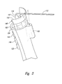
- system 100 further comprises skirt 148 , extending from housing 104 adjacent to nozzle 107 .
- Skirt 148 is configured to impart a compaction force against continuous flexible line 112 after continuous flexible line 112 exits outlet 110 of nozzle 107 responsive to application of a force toward skirt 148 .
- skirt 148 Responsive to an applied force, for example, via housing 104 , skirt 148 is used to impart a compaction force against continuous flexible line 112 after it exits nozzle 107 and is deposited against a surface or against a prior deposited layer of continuous flexible line 112 . Accordingly, adjacent layers of continuous flexible line 112 that have been deposited via nozzle 107 may be compacted together. By extending from housing 104 adjacent to nozzle 107 , skirt 148 is positioned to compact continuous flexible line 112 as it exits nozzle 107 . The applied force may be responsive to a user or a robot pushing on housing 104 toward skirt 148 and toward continuous flexible line 112 that has exited nozzle 107 .
- skirt 148 extends only partially circumferentially around nozzle 107 .
- a user may more easily view continuous flexible line 112 as it exits nozzle and thus more easily manipulate movement of nozzle 104 in a desired orientation and direction for deposition of continuous flexible line 112 .
- skirt 148 extends from the same side of housing 104 , on which light source 120 is positioned. Accordingly, skirt 148 and light source 120 are positioned on a side of housing that is intended to trail movement of housing 104 and nozzle 107 during deposition, compaction, and curing of continuous flexible line 112 .
- skirt 148 comprises viewing window 162 , configured to provide a line of sight through skirt 148 to nozzle 107 .
- Viewing window 162 provides a line of sight through skirt 148 to nozzle 107 , so that a user may more easily observe continuous flexible line 112 exiting nozzle 107 .
- Viewing window 162 may be formed from a transparent material.
- skirt 148 may define an open passage as viewing window 162 with no material being present within viewing window 162 .
- skirt 148 comprises a resilient material.
- skirt 148 may deform slightly responsive to a compaction force applied against continuous flexible line 112 . As a result, a user may more easily control a desired level of compaction and avoid unintended scraping of continuous flexible line, such as that may result in inadvertent removal of photopolymer-resin component 116 that may be caused by a more rigid construction of skirt 148 .
- Non-exhaustive examples of resilient materials from which skirt 148 may be constructed include rubbers and silicones.
- skirt 148 comprises rim 152 , which is textured to impart a texture to continuous flexible line 112 responsive to the compaction force and to relative movement between skirt 148 and continuous flexible line 112 .
- rim 152 which is textured to impart a texture to continuous flexible line 112 responsive to the compaction force and to relative movement between skirt 148 and continuous flexible line 112 .
- rim 152 When rim 152 is textured, rim 152 imparts a texture to continuous flexible line 112 when compacting continuous flexible line 112 , providing it with increased surface area for better adhesion of a subsequent layer of continuous flexible line 112 deposited against it.
- outlet 110 of the nozzle ( 107 ) is configured to impart a texture to continuous flexible line 112 as continuous flexible line 112 exits outlet 110 of nozzle 107 .
- continuous flexible line 112 By imparting a texture to continuous flexible line 112 as it exits nozzle 107 , a desired adhesion between layers of continuous flexible line 112 being deposited may be achieved. Moreover, a texture to an entirety of the circumference of continuous flexible line 112 results, thereby facilitating adhesion not only between vertically adjacent layers of continuous flexible line 112 , but also between laterally adjacent extensions of continuous flexible line 112 .
- light source 120 comprises light-source input mechanism 122 , supported by housing 104 and configured to selectively actuate the light beam responsive to an external input to selectively and at least partially cure photopolymer-resin component 116 of continuous flexible line 112 .
- the preceding subject matter of this paragraph characterizes example 36 of the present disclosure, wherein example 36 also includes the subject matter according to any one of examples 1 to 35, above.
- Light-source input mechanism 122 selectively actuates light source 120 so that the light beam will become incident upon continuous flexible line 112 after exiting nozzle 107 at thereby at least partially cure continuous flexible line 112 as composite part 102 is being manufactured.
- Light-source input mechanism 122 may take any suitable form, including (but not limited to) one or more buttons, dials, switches, etc. that are configured to receive an external input from a user to selectively actuate light source 120 .
- light source 120 comprises light frequency adjustment mechanism 178 , configured to selectively adjust a pulse frequency of light source 120 responsive to an external input.
- light frequency adjustment mechanism 178 configured to selectively adjust a pulse frequency of light source 120 responsive to an external input.
- Light frequency adjustment mechanism 178 provides a way for a user to selectively adjust and select a desired pulse frequency of light source 120 .
- different pulse frequencies may be desired to impart different levels of cure of continuous flexible line 112 and/or different types of photopolymer-resin components 116 may require different pulse frequencies for a desired amount of cure.
- Light frequency adjustment mechanism 178 may take any suitable form, including (but not limited to) one or more buttons, dials, switches, etc. that are configured to receive an external input from a user to adjust the pulse frequency of light source 120 .
- light frequency adjustment mechanism 178 may be continuously adjustable, such as via a potentiometer, and in other examples, light frequency adjustment mechanism 178 may have discrete settings, such as with two more set pulse frequency settings for light source 120 .
- light source 120 comprises light duration adjustment mechanism 180 , configured to selectively adjust a duration of light source 120 responsive to an external input.
- light duration adjustment mechanism 180 configured to selectively adjust a duration of light source 120 responsive to an external input.
- Light duration adjustment mechanism 180 provides a way for a user to selectively adjust and select a desired duration of light source 120 emitting the light beam.
- Light duration adjustment mechanism 180 may take any suitable form, including (but not limited to) one or more buttons, dials, switches, etc. that are configured to receive an external input from a user to adjust the duration of light source 120 emitting the light beam.
- light duration adjustment mechanism 180 may be continuously adjustable, such as via a potentiometer, and in other examples, light duration adjustment mechanism 180 may have discrete settings, such as with two more set durations of time for light source 120 to emit the light beam.
- system 100 further comprises one or more templates 156 , configured to be placed against surface 108 .
- Each template 156 comprises a boundary configured to define composite part 102 when continuous flexible line 112 is dispensed from nozzle 107 within the boundary.
- Templates 156 may provide an efficient way for a user to create a desired composite part 102 by providing a boundary within which continuous flexible line 112 may be easily deposited by system 100 .
- such templates may be used to create replacement parts in the field, such as to repair a damaged part of an apparatus, such as a vehicle, an aircraft, or any other apparatus requiring repair.
- one or more templates 156 correspond to one or more unique parts to be manufactured by system 100 .
- the preceding subject matter of this paragraph characterizes example 40 of the present disclosure, wherein example 40 also includes the subject matter according to example 39, above.
- various composite parts 102 may be easily manufactured with system 100 .
- housing 104 is sized to be held and manipulated by a human user.
- the preceding subject matter of this paragraph characterizes example 41 of the present disclosure, wherein example 41 also includes the subject matter according to any one of examples 1 to 40, above.
- housing 104 and system 100 may be easily transportable and used to manufacture composite parts 102 at any desired location, including in the field, such as to repair or replace a damaged part.
- housing 104 may be sized to be held and manipulated by a single hand of a human user. In some examples, housing 104 may be sized to be held and manipulated by both hands of a human user.
- housing 104 and/or system 100 may be sized and configured to be used as an end effector of a robot, such as a robotic arm.
- system 100 further comprises controller 160 and one or more of pump 132 , operatively coupled to resin tank 128 , and configured to deliver photopolymer resin 130 from resin tank 128 to non-resin component 114 to create photopolymer-resin component 116 as feed mechanism 118 pushes continuous flexible line 112 out of outlet 110 of nozzle 107 ; pump adjustment mechanism 176 , supported by housing 104 that is operatively coupled to pump 132 and is configured to selectively adjust a pump rate of pump 132 responsive to an external input; motor 138 , operatively coupled to roller 136 and configured to selectively rotate roller 136 to push continuous flexible line 112 out of outlet 110 of nozzle 107 ; feed input mechanism 140 , supported by housing 104 and configured to selectively actuate motor 138 when feed input mechanism 140 receives an external input; feed adjustment mechanism 174 , supported by housing 104 and configured to selectively adjust a rotational speed of motor 138 responsive to an external input; cutter 142 , supported by housing 104 , supported by housing 104
- Controller 160 is communicatively coupled to one or more of feed mechanism 118 , light source 120 , pump 132 , pump adjustment mechanism 176 , motor 138 , feed input mechanism 140 , feed adjustment mechanism 174 , cutter 142 , cutter input mechanism 146 , light-source input mechanism 122 , light frequency adjustment mechanism 178 , and light duration adjustment mechanism 180 .
- Controller 160 is programmed to selectively operate one or more of feed mechanism 118 , light source 120 , pump 132 , motor 138 , and cutter 142 .
- Controller 160 controls the operation of various component parts of system 100 .
- Controller 160 may include any suitable structure that may be adapted, configured, designed, constructed, and/or programmed to control the operation of at least a portion of system 100 .
- controller 160 may include and/or be an electronic controller, a dedicated controller, a special-purpose controller, a personal computer, a display device, a logic device, and/or a memory device.
- controller 160 may be programmed to perform one or more algorithms to automatically control the operation of system 100 .
- controller 160 may comprise an ARDUINOTM Pro Mini micro controller board with an ATmega328 micro controller.
- system 100 further comprises battery 164 , operatively coupled to one or more of controller 160 , feed mechanism 118 , light source 120 , pump 132 , pump adjustment mechanism 176 , motor 138 , feed input mechanism 140 , feed adjustment mechanism 174 , cutter 142 , cutter input mechanism 146 , light-source input mechanism 122 , light frequency adjustment mechanism 178 , and light duration adjustment mechanism 180 .
- controller 160 operatively coupled to one or more of controller 160 , feed mechanism 118 , light source 120 , pump 132 , pump adjustment mechanism 176 , motor 138 , feed input mechanism 140 , feed adjustment mechanism 174 , cutter 142 , cutter input mechanism 146 , light-source input mechanism 122 , light frequency adjustment mechanism 178 , and light duration adjustment mechanism 180 .
- Battery 164 provides power for various component parts of system 100 .
- system 100 further comprises line tube 166 , supported by housing 104 and configured to provide a path at least for non-resin component 114 to and from feed mechanism 118 and to nozzle 107 .
- line tube 166 supported by housing 104 and configured to provide a path at least for non-resin component 114 to and from feed mechanism 118 and to nozzle 107 .
- Line tube 166 provides a path for non-resin component 114 or continuous flexible line 112 to travel to and from feed mechanism 118 and to nozzle 107 .
- line tube 166 provides a path for continuous flexible line 112 .
- line tube 166 provides a path for non-resin component 114 .
- illustrative method 1100 may include specification and design (block 1104 ) of aircraft 1102 and material procurement (block 1106 ).
- material procurement block 1106
- component and subassembly manufacturing block 1108
- system integration block 1110
- aircraft 1102 may go through certification and delivery (block 1112 ) to be placed in service (block 1114 ).
- aircraft 1102 may be scheduled for routine maintenance and service (block 1116 ). Routine maintenance and service may include modification, reconfiguration, refurbishment, etc. of one or more systems of aircraft 1102 .
- a system integrator may include, without limitation, any number of aircraft manufacturers and major-system subcontractors; a third party may include, without limitation, any number of vendors, subcontractors, and suppliers; and an operator may be an airline, leasing company, military entity, service organization, and so on.
- aircraft 1102 produced by illustrative method 1100 may include airframe 1118 with a plurality of high-level systems 1120 and interior 1122 .
- high-level systems 1120 include one or more of propulsion system 1124 , electrical system 1126 , hydraulic system 1128 , and environmental system 1130 . Any number of other systems may be included.
- propulsion system 1124 the principles disclosed herein may be applied to other industries, such as the automotive industry. Accordingly, in addition to aircraft 1102 , the principles disclosed herein may apply to other vehicles, e.g., land vehicles, marine vehicles, space vehicles, etc.
- Apparatus(es) and method(s) shown or described herein may be employed during any one or more of the stages of the manufacturing and service method 1100 .
- components or subassemblies corresponding to component and subassembly manufacturing (block 1108 ) may be fabricated or manufactured in a manner similar to components or subassemblies produced while aircraft 1102 is in service (block 1114 ).
- one or more examples of the apparatus(es), method(s), or combination thereof may be utilized during production stages 1108 and 1110 , for example, by substantially expediting assembly of or reducing the cost of aircraft 1102 .
- one or more examples of the apparatus or method realizations, or a combination thereof may be utilized, for example and without limitation, while aircraft 1102 is in service (block 1114 ) and/or during maintenance and service (block 1116 ).
Landscapes
- Engineering & Computer Science (AREA)
- Chemical & Material Sciences (AREA)
- Materials Engineering (AREA)
- Mechanical Engineering (AREA)
- Physics & Mathematics (AREA)
- Manufacturing & Machinery (AREA)
- Optics & Photonics (AREA)
- Composite Materials (AREA)
- Health & Medical Sciences (AREA)
- Plasma & Fusion (AREA)
- Organic Chemistry (AREA)
- Life Sciences & Earth Sciences (AREA)
- Wood Science & Technology (AREA)
- Clinical Laboratory Science (AREA)
- Structural Engineering (AREA)
- Ceramic Engineering (AREA)
- Civil Engineering (AREA)
- Textile Engineering (AREA)
- Robotics (AREA)
- Oral & Maxillofacial Surgery (AREA)
- Toxicology (AREA)
- General Health & Medical Sciences (AREA)
- Thermal Sciences (AREA)
- Casting Or Compression Moulding Of Plastics Or The Like (AREA)
Abstract
Description
Claims (35)
Priority Applications (1)
| Application Number | Priority Date | Filing Date | Title |
|---|---|---|---|
| US15/087,882 US10071545B2 (en) | 2015-07-31 | 2016-03-31 | Systems for additively manufacturing composite parts |
Applications Claiming Priority (2)
| Application Number | Priority Date | Filing Date | Title |
|---|---|---|---|
| US201562199665P | 2015-07-31 | 2015-07-31 | |
| US15/087,882 US10071545B2 (en) | 2015-07-31 | 2016-03-31 | Systems for additively manufacturing composite parts |
Publications (2)
| Publication Number | Publication Date |
|---|---|
| US20170028640A1 US20170028640A1 (en) | 2017-02-02 |
| US10071545B2 true US10071545B2 (en) | 2018-09-11 |
Family
ID=57885857
Family Applications (14)
| Application Number | Title | Priority Date | Filing Date |
|---|---|---|---|
| US14/841,504 Active 2036-09-01 US10279580B2 (en) | 2015-07-31 | 2015-08-31 | Method for additively manufacturing composite parts |
| US14/841,472 Active 2036-08-20 US10131132B2 (en) | 2015-07-31 | 2015-08-31 | Methods for additively manufacturing composite parts |
| US14/841,524 Active 2036-11-08 US10166752B2 (en) | 2015-07-31 | 2015-08-31 | Methods for additively manufacturing composite parts |
| US14/841,500 Active 2036-06-16 US10112380B2 (en) | 2015-07-31 | 2015-08-31 | Methods for additively manufacturing composite parts |
| US14/920,779 Active 2036-10-09 US10189240B2 (en) | 2015-07-31 | 2015-10-22 | Methods for additively manufacturing composite parts |
| US14/920,767 Active 2036-09-23 US10166753B2 (en) | 2015-07-31 | 2015-10-22 | Systems and methods for additively manufacturing composite parts |
| US14/931,635 Active 2036-09-08 US10189241B2 (en) | 2015-07-31 | 2015-11-03 | Methods for additively manufacturing composite parts |
| US14/931,692 Active 2036-09-26 US10183478B2 (en) | 2015-07-31 | 2015-11-03 | Methods for additively manufacturing composite parts |
| US14/995,620 Active 2036-07-10 US10189242B2 (en) | 2015-07-31 | 2016-01-14 | Methods for additively manufacturing composite parts |
| US14/995,742 Active 2036-06-11 US10124570B2 (en) | 2015-07-31 | 2016-01-14 | Methods for additively manufacturing composite parts |
| US15/063,417 Active 2036-07-04 US10179446B2 (en) | 2015-07-31 | 2016-03-07 | Methods for additively manufacturing composite parts |
| US15/063,347 Active 2037-08-31 US10350878B2 (en) | 2015-07-31 | 2016-03-07 | Systems for additively manufacturing composite parts |
| US15/063,443 Active 2036-07-08 US10183479B2 (en) | 2015-07-31 | 2016-03-07 | Methods for additively manufacturing composite parts |
| US15/087,882 Active 2036-05-31 US10071545B2 (en) | 2015-07-31 | 2016-03-31 | Systems for additively manufacturing composite parts |
Family Applications Before (13)
| Application Number | Title | Priority Date | Filing Date |
|---|---|---|---|
| US14/841,504 Active 2036-09-01 US10279580B2 (en) | 2015-07-31 | 2015-08-31 | Method for additively manufacturing composite parts |
| US14/841,472 Active 2036-08-20 US10131132B2 (en) | 2015-07-31 | 2015-08-31 | Methods for additively manufacturing composite parts |
| US14/841,524 Active 2036-11-08 US10166752B2 (en) | 2015-07-31 | 2015-08-31 | Methods for additively manufacturing composite parts |
| US14/841,500 Active 2036-06-16 US10112380B2 (en) | 2015-07-31 | 2015-08-31 | Methods for additively manufacturing composite parts |
| US14/920,779 Active 2036-10-09 US10189240B2 (en) | 2015-07-31 | 2015-10-22 | Methods for additively manufacturing composite parts |
| US14/920,767 Active 2036-09-23 US10166753B2 (en) | 2015-07-31 | 2015-10-22 | Systems and methods for additively manufacturing composite parts |
| US14/931,635 Active 2036-09-08 US10189241B2 (en) | 2015-07-31 | 2015-11-03 | Methods for additively manufacturing composite parts |
| US14/931,692 Active 2036-09-26 US10183478B2 (en) | 2015-07-31 | 2015-11-03 | Methods for additively manufacturing composite parts |
| US14/995,620 Active 2036-07-10 US10189242B2 (en) | 2015-07-31 | 2016-01-14 | Methods for additively manufacturing composite parts |
| US14/995,742 Active 2036-06-11 US10124570B2 (en) | 2015-07-31 | 2016-01-14 | Methods for additively manufacturing composite parts |
| US15/063,417 Active 2036-07-04 US10179446B2 (en) | 2015-07-31 | 2016-03-07 | Methods for additively manufacturing composite parts |
| US15/063,347 Active 2037-08-31 US10350878B2 (en) | 2015-07-31 | 2016-03-07 | Systems for additively manufacturing composite parts |
| US15/063,443 Active 2036-07-08 US10183479B2 (en) | 2015-07-31 | 2016-03-07 | Methods for additively manufacturing composite parts |
Country Status (1)
| Country | Link |
|---|---|
| US (14) | US10279580B2 (en) |
Cited By (1)
| Publication number | Priority date | Publication date | Assignee | Title |
|---|---|---|---|---|
| US12030226B1 (en) | 2020-12-17 | 2024-07-09 | The Boeing Company | Apparatus and method for forming electromagnetic shielding material |
Families Citing this family (175)
| Publication number | Priority date | Publication date | Assignee | Title |
|---|---|---|---|---|
| US10653824B2 (en) | 2012-05-25 | 2020-05-19 | Lockheed Martin Corporation | Two-dimensional materials and uses thereof |
| US9511543B2 (en) | 2012-08-29 | 2016-12-06 | Cc3D Llc | Method and apparatus for continuous composite three-dimensional printing |
| US9572918B2 (en) | 2013-06-21 | 2017-02-21 | Lockheed Martin Corporation | Graphene-based filter for isolating a substance from blood |
| CN106029596A (en) | 2014-01-31 | 2016-10-12 | 洛克希德马丁公司 | Processes for forming composite structures with a two-dimensional material using a porous, non-sacrificial supporting layer |
| ES2770053T3 (en) | 2014-05-16 | 2020-06-30 | Divergent Tech Inc | Modular formed nodes for vehicle chassis and their methods of use |
| EP3925766B1 (en) | 2014-07-02 | 2023-11-08 | Divergent Technologies, Inc. | Tubular frame of vehicle |
| WO2017023377A1 (en) | 2015-08-06 | 2017-02-09 | Lockheed Martin Corporation | Nanoparticle modification and perforation of graphene |
| EP3341179A4 (en) * | 2015-08-25 | 2019-10-30 | University of South Carolina | INTEGRATED ROBOTIC 3D PRINTING SYSTEM FOR PRINTING FIBER REINFORCED PIECES |
| EP4137256A1 (en) | 2015-10-30 | 2023-02-22 | Seurat Technologies, Inc. | Additive manufacturing system and method |
| US10259209B2 (en) * | 2015-12-14 | 2019-04-16 | International Business Machines Corporation | Pulsed UV light nozzle for selective curing of 3D printed material |
| WO2017106965A1 (en) * | 2015-12-21 | 2017-06-29 | Ord Solutions Inc. | Method and apparatus for large format three-dimensional printing |
| US10611073B2 (en) | 2015-12-28 | 2020-04-07 | Thermwood Corporation | Machine and method for forming articles |
| WO2017180134A1 (en) | 2016-04-14 | 2017-10-19 | Lockheed Martin Corporation | Methods for in vivo and in vitro use of graphene and other two-dimensional materials |
| EP3442697A4 (en) | 2016-04-14 | 2020-03-18 | Lockheed Martin Corporation | Selective interfacial mitigation of graphene defects |
| US10232551B2 (en) * | 2016-04-15 | 2019-03-19 | Cc3D Llc | Head and system for continuously manufacturing composite hollow structure |
| KR20190006593A (en) | 2016-06-09 | 2019-01-18 | 디버전트 테크놀로지스, 인크. | Systems and methods for arc and node design and fabrication |
| US10543640B2 (en) | 2016-09-06 | 2020-01-28 | Continuous Composites Inc. | Additive manufacturing system having in-head fiber teasing |
| US10759113B2 (en) | 2016-09-06 | 2020-09-01 | Continuous Composites Inc. | Additive manufacturing system having trailing cure mechanism |
| US10216165B2 (en) | 2016-09-06 | 2019-02-26 | Cc3D Llc | Systems and methods for controlling additive manufacturing |
| US20180065317A1 (en) | 2016-09-06 | 2018-03-08 | Cc3D Llc | Additive manufacturing system having in-situ fiber splicing |
| US10625467B2 (en) | 2016-09-06 | 2020-04-21 | Continuous Composites Inc. | Additive manufacturing system having adjustable curing |
| US10717512B2 (en) | 2016-11-03 | 2020-07-21 | Continuous Composites Inc. | Composite vehicle body |
| US10953598B2 (en) | 2016-11-04 | 2021-03-23 | Continuous Composites Inc. | Additive manufacturing system having vibrating nozzle |
| US20210094230A9 (en) | 2016-11-04 | 2021-04-01 | Continuous Composites Inc. | System for additive manufacturing |
| US10576683B2 (en) * | 2017-01-16 | 2020-03-03 | The Boeing Company | Multi-part filaments for additive manufacturing and related systems and methods |
| US10857726B2 (en) | 2017-01-24 | 2020-12-08 | Continuous Composites Inc. | Additive manufacturing system implementing anchor curing |
| US10040240B1 (en) | 2017-01-24 | 2018-08-07 | Cc3D Llc | Additive manufacturing system having fiber-cutting mechanism |
| US11155005B2 (en) | 2017-02-10 | 2021-10-26 | Divergent Technologies, Inc. | 3D-printed tooling and methods for producing same |
| US10759090B2 (en) | 2017-02-10 | 2020-09-01 | Divergent Technologies, Inc. | Methods for producing panels using 3D-printed tooling shells |
| US20180229092A1 (en) | 2017-02-13 | 2018-08-16 | Cc3D Llc | Composite sporting equipment |
| US10798783B2 (en) | 2017-02-15 | 2020-10-06 | Continuous Composites Inc. | Additively manufactured composite heater |
| US10549477B2 (en) * | 2017-02-17 | 2020-02-04 | Thermwood Corporation | Methods and apparatus for controlling an applicator head during additive manufacturing |
| US10500785B2 (en) | 2017-02-17 | 2019-12-10 | Thermwood Corporation | Methods and apparatus for compensating for material distortion during additive manufacturing |
| US11117362B2 (en) | 2017-03-29 | 2021-09-14 | Tighitco, Inc. | 3D printed continuous fiber reinforced part |
| DE102017108720A1 (en) * | 2017-04-24 | 2018-10-25 | Dohle Extrusionstechnik Gmbh | extrusion device |
| US12251884B2 (en) | 2017-04-28 | 2025-03-18 | Divergent Technologies, Inc. | Support structures in additive manufacturing |
| US10898968B2 (en) | 2017-04-28 | 2021-01-26 | Divergent Technologies, Inc. | Scatter reduction in additive manufacturing |
| US20180319943A1 (en) * | 2017-05-08 | 2018-11-08 | Lockheed Martin Corporation | Porous membrane and membrane support with integrated high permeability barrier |
| US10703419B2 (en) | 2017-05-19 | 2020-07-07 | Divergent Technologies, Inc. | Apparatus and methods for joining panels |
| US11358337B2 (en) | 2017-05-24 | 2022-06-14 | Divergent Technologies, Inc. | Robotic assembly of transport structures using on-site additive manufacturing |
| US11123973B2 (en) | 2017-06-07 | 2021-09-21 | Divergent Technologies, Inc. | Interconnected deflectable panel and node |
| US10919230B2 (en) | 2017-06-09 | 2021-02-16 | Divergent Technologies, Inc. | Node with co-printed interconnect and methods for producing same |
| US10781846B2 (en) | 2017-06-19 | 2020-09-22 | Divergent Technologies, Inc. | 3-D-printed components including fasteners and methods for producing same |
| US10589463B2 (en) * | 2017-06-29 | 2020-03-17 | Continuous Composites Inc. | Print head for additive manufacturing system |
| US10814569B2 (en) | 2017-06-29 | 2020-10-27 | Continuous Composites Inc. | Method and material for additive manufacturing |
| US10994876B2 (en) | 2017-06-30 | 2021-05-04 | Divergent Technologies, Inc. | Automated wrapping of components in transport structures |
| US11022375B2 (en) | 2017-07-06 | 2021-06-01 | Divergent Technologies, Inc. | Apparatus and methods for additively manufacturing microtube heat exchangers |
| US10895315B2 (en) | 2017-07-07 | 2021-01-19 | Divergent Technologies, Inc. | Systems and methods for implementing node to node connections in mechanized assemblies |
| US10751800B2 (en) | 2017-07-25 | 2020-08-25 | Divergent Technologies, Inc. | Methods and apparatus for additively manufactured exoskeleton-based transport structures |
| US10940609B2 (en) | 2017-07-25 | 2021-03-09 | Divergent Technologies, Inc. | Methods and apparatus for additively manufactured endoskeleton-based transport structures |
| US10605285B2 (en) | 2017-08-08 | 2020-03-31 | Divergent Technologies, Inc. | Systems and methods for joining node and tube structures |
| US10357959B2 (en) | 2017-08-15 | 2019-07-23 | Divergent Technologies, Inc. | Methods and apparatus for additively manufactured identification features |
| US11306751B2 (en) | 2017-08-31 | 2022-04-19 | Divergent Technologies, Inc. | Apparatus and methods for connecting tubes in transport structures |
| US10960611B2 (en) | 2017-09-06 | 2021-03-30 | Divergent Technologies, Inc. | Methods and apparatuses for universal interface between parts in transport structures |
| US11292058B2 (en) | 2017-09-12 | 2022-04-05 | Divergent Technologies, Inc. | Apparatus and methods for optimization of powder removal features in additively manufactured components |
| US10612569B2 (en) | 2017-09-18 | 2020-04-07 | General Electric Company | Additively manufactured rotary actuator |
| US10982851B2 (en) | 2017-09-18 | 2021-04-20 | General Electric Company | Additively manufactured wall and floating ferrule having a frangible member between the floating ferrule and a build support arm |
| US10557555B2 (en) | 2017-09-18 | 2020-02-11 | General Electric Company | Additively manufactured valve assembly |
| US10766195B2 (en) * | 2017-10-05 | 2020-09-08 | The Boeing Company | Additive manufacturing fiber composites and related systems and methods |
| US10668816B2 (en) | 2017-10-11 | 2020-06-02 | Divergent Technologies, Inc. | Solar extended range electric vehicle with panel deployment and emitter tracking |
| US10814564B2 (en) | 2017-10-11 | 2020-10-27 | Divergent Technologies, Inc. | Composite material inlay in additively manufactured structures |
| US11564756B2 (en) * | 2017-10-30 | 2023-01-31 | Cilag Gmbh International | Method of hub communication with surgical instrument systems |
| US11786971B2 (en) | 2017-11-10 | 2023-10-17 | Divergent Technologies, Inc. | Structures and methods for high volume production of complex structures using interface nodes |
| US10319499B1 (en) | 2017-11-30 | 2019-06-11 | Cc3D Llc | System and method for additively manufacturing composite wiring harness |
| US10926599B2 (en) | 2017-12-01 | 2021-02-23 | Divergent Technologies, Inc. | Suspension systems using hydraulic dampers |
| US11110514B2 (en) | 2017-12-14 | 2021-09-07 | Divergent Technologies, Inc. | Apparatus and methods for connecting nodes to tubes in transport structures |
| US10131088B1 (en) | 2017-12-19 | 2018-11-20 | Cc3D Llc | Additive manufacturing method for discharging interlocking continuous reinforcement |
| US11085473B2 (en) | 2017-12-22 | 2021-08-10 | Divergent Technologies, Inc. | Methods and apparatus for forming node to panel joints |
| US11534828B2 (en) | 2017-12-27 | 2022-12-27 | Divergent Technologies, Inc. | Assembling structures comprising 3D printed components and standardized components utilizing adhesive circuits |
| US10919222B2 (en) | 2017-12-29 | 2021-02-16 | Continuous Composites Inc. | System and method for additively manufacturing functional elements into existing components |
| US20190202130A1 (en) * | 2017-12-29 | 2019-07-04 | Cc3D Llc | System and method for additively manufacturing functional elements into existing components |
| US10081129B1 (en) | 2017-12-29 | 2018-09-25 | Cc3D Llc | Additive manufacturing system implementing hardener pre-impregnation |
| US10759114B2 (en) | 2017-12-29 | 2020-09-01 | Continuous Composites Inc. | System and print head for continuously manufacturing composite structure |
| US11167495B2 (en) | 2017-12-29 | 2021-11-09 | Continuous Composites Inc. | System and method for additively manufacturing functional elements into existing components |
| US10857729B2 (en) | 2017-12-29 | 2020-12-08 | Continuous Composites Inc. | System and method for additively manufacturing functional elements into existing components |
| US11420262B2 (en) | 2018-01-31 | 2022-08-23 | Divergent Technologies, Inc. | Systems and methods for co-casting of additively manufactured interface nodes |
| US10751934B2 (en) | 2018-02-01 | 2020-08-25 | Divergent Technologies, Inc. | Apparatus and methods for additive manufacturing with variable extruder profiles |
| US11224943B2 (en) | 2018-03-07 | 2022-01-18 | Divergent Technologies, Inc. | Variable beam geometry laser-based powder bed fusion |
| US11267236B2 (en) | 2018-03-16 | 2022-03-08 | Divergent Technologies, Inc. | Single shear joint for node-to-node connections |
| US11254381B2 (en) | 2018-03-19 | 2022-02-22 | Divergent Technologies, Inc. | Manufacturing cell based vehicle manufacturing system and method |
| US11872689B2 (en) | 2018-03-19 | 2024-01-16 | Divergent Technologies, Inc. | End effector features for additively manufactured components |
| US11408216B2 (en) | 2018-03-20 | 2022-08-09 | Divergent Technologies, Inc. | Systems and methods for co-printed or concurrently assembled hinge structures |
| US11161300B2 (en) | 2018-04-11 | 2021-11-02 | Continuous Composites Inc. | System and print head for additive manufacturing system |
| US11110656B2 (en) | 2018-04-12 | 2021-09-07 | Continuous Composites Inc. | System for continuously manufacturing composite structure |
| US11130284B2 (en) | 2018-04-12 | 2021-09-28 | Continuous Composites Inc. | System and head for continuously manufacturing composite structure |
| US11613078B2 (en) | 2018-04-20 | 2023-03-28 | Divergent Technologies, Inc. | Apparatus and methods for additively manufacturing adhesive inlet and outlet ports |
| US11214317B2 (en) | 2018-04-24 | 2022-01-04 | Divergent Technologies, Inc. | Systems and methods for joining nodes and other structures |
| US10682821B2 (en) | 2018-05-01 | 2020-06-16 | Divergent Technologies, Inc. | Flexible tooling system and method for manufacturing of composite structures |
| US11020800B2 (en) | 2018-05-01 | 2021-06-01 | Divergent Technologies, Inc. | Apparatus and methods for sealing powder holes in additively manufactured parts |
| US11389816B2 (en) | 2018-05-09 | 2022-07-19 | Divergent Technologies, Inc. | Multi-circuit single port design in additively manufactured node |
| US10691104B2 (en) | 2018-05-16 | 2020-06-23 | Divergent Technologies, Inc. | Additively manufacturing structures for increased spray forming resolution or increased fatigue life |
| US11590727B2 (en) | 2018-05-21 | 2023-02-28 | Divergent Technologies, Inc. | Custom additively manufactured core structures |
| US11441586B2 (en) | 2018-05-25 | 2022-09-13 | Divergent Technologies, Inc. | Apparatus for injecting fluids in node based connections |
| US10618210B2 (en) * | 2018-05-30 | 2020-04-14 | Corning Incorporated | High capacity print station, method of making a polymer composite part, and polymer composite part |
| US11035511B2 (en) | 2018-06-05 | 2021-06-15 | Divergent Technologies, Inc. | Quick-change end effector |
| US11052603B2 (en) | 2018-06-07 | 2021-07-06 | Continuous Composites Inc. | Additive manufacturing system having stowable cutting mechanism |
| US11046415B1 (en) | 2018-06-20 | 2021-06-29 | United States of Americas as represented by the Secretary of the Air Force | Multi-material printed control surface |
| US11292056B2 (en) | 2018-07-06 | 2022-04-05 | Divergent Technologies, Inc. | Cold-spray nozzle |
| US11269311B2 (en) | 2018-07-26 | 2022-03-08 | Divergent Technologies, Inc. | Spray forming structural joints |
| US10787846B2 (en) | 2018-08-03 | 2020-09-29 | General Electric Company | Additively manufactured hinge assembly |
| US10836120B2 (en) | 2018-08-27 | 2020-11-17 | Divergent Technologies, Inc . | Hybrid composite structures with integrated 3-D printed elements |
| US11433557B2 (en) | 2018-08-28 | 2022-09-06 | Divergent Technologies, Inc. | Buffer block apparatuses and supporting apparatuses |
| US11826953B2 (en) | 2018-09-12 | 2023-11-28 | Divergent Technologies, Inc. | Surrogate supports in additive manufacturing |
| US20200086563A1 (en) * | 2018-09-13 | 2020-03-19 | Cc3D Llc | System and head for continuously manufacturing composite structure |
| US11235522B2 (en) | 2018-10-04 | 2022-02-01 | Continuous Composites Inc. | System for additively manufacturing composite structures |
| US11072371B2 (en) | 2018-10-05 | 2021-07-27 | Divergent Technologies, Inc. | Apparatus and methods for additively manufactured structures with augmented energy absorption properties |
| US11260582B2 (en) | 2018-10-16 | 2022-03-01 | Divergent Technologies, Inc. | Methods and apparatus for manufacturing optimized panels and other composite structures |
| US11511480B2 (en) | 2018-10-26 | 2022-11-29 | Continuous Composites Inc. | System for additive manufacturing |
| US12115583B2 (en) | 2018-11-08 | 2024-10-15 | Divergent Technologies, Inc. | Systems and methods for adhesive-based part retention features in additively manufactured structures |
| US12194536B2 (en) | 2018-11-13 | 2025-01-14 | Divergent Technologies, Inc. | 3-D printer with manifolds for gas exchange |
| US11358331B2 (en) | 2018-11-19 | 2022-06-14 | Continuous Composites Inc. | System and head for continuously manufacturing composite structure |
| US11420390B2 (en) | 2018-11-19 | 2022-08-23 | Continuous Composites Inc. | System for additively manufacturing composite structure |
| US11504912B2 (en) | 2018-11-20 | 2022-11-22 | Divergent Technologies, Inc. | Selective end effector modular attachment device |
| USD911222S1 (en) | 2018-11-21 | 2021-02-23 | Divergent Technologies, Inc. | Vehicle and/or replica |
| US11529741B2 (en) | 2018-12-17 | 2022-12-20 | Divergent Technologies, Inc. | System and method for positioning one or more robotic apparatuses |
| US11449021B2 (en) | 2018-12-17 | 2022-09-20 | Divergent Technologies, Inc. | Systems and methods for high accuracy fixtureless assembly |
| US10663110B1 (en) | 2018-12-17 | 2020-05-26 | Divergent Technologies, Inc. | Metrology apparatus to facilitate capture of metrology data |
| CN109605598B (en) * | 2018-12-20 | 2020-11-24 | 重庆七彩虹新材料技术有限公司 | Preparation process of powder coating |
| US11885000B2 (en) | 2018-12-21 | 2024-01-30 | Divergent Technologies, Inc. | In situ thermal treatment for PBF systems |
| US12378643B2 (en) | 2019-01-18 | 2025-08-05 | Divergent Technologies, Inc. | Aluminum alloys |
| US20200238603A1 (en) | 2019-01-25 | 2020-07-30 | Continuous Composites Inc. | System for additively manufacturing composite structure |
| KR20210127233A (en) * | 2019-02-20 | 2021-10-21 | 럭섹셀 홀딩 비.브이. | Optical article printing method |
| US11203240B2 (en) | 2019-04-19 | 2021-12-21 | Divergent Technologies, Inc. | Wishbone style control arm assemblies and methods for producing same |
| US20200376758A1 (en) | 2019-05-28 | 2020-12-03 | Continuous Composites Inc. | System for additively manufacturing composite structure |
| US12314031B1 (en) | 2019-06-27 | 2025-05-27 | Divergent Technologies, Inc. | Incorporating complex geometric features in additively manufactured parts |
| US11724456B2 (en) * | 2019-09-18 | 2023-08-15 | Mighty Buildings, Inc. | Optical curing system for 3D printing |
| US12280554B2 (en) | 2019-11-21 | 2025-04-22 | Divergent Technologies, Inc. | Fixtureless robotic assembly |
| US11465343B2 (en) * | 2019-12-17 | 2022-10-11 | Saudi Arabian Oil Company | Manufacturing continuous fiber reinforced thermoplastic components with layers of unidirectional tape |
| US11794402B2 (en) | 2019-12-18 | 2023-10-24 | Saudi Arabian Oil Company | Reducing manufacturing defects of a wound filament product |
| US11840022B2 (en) | 2019-12-30 | 2023-12-12 | Continuous Composites Inc. | System and method for additive manufacturing |
| US11912339B2 (en) | 2020-01-10 | 2024-02-27 | Divergent Technologies, Inc. | 3-D printed chassis structure with self-supporting ribs |
| US11590703B2 (en) | 2020-01-24 | 2023-02-28 | Divergent Technologies, Inc. | Infrared radiation sensing and beam control in electron beam additive manufacturing |
| US11479015B2 (en) | 2020-02-14 | 2022-10-25 | Divergent Technologies, Inc. | Custom formed panels for transport structures and methods for assembling same |
| US11884025B2 (en) | 2020-02-14 | 2024-01-30 | Divergent Technologies, Inc. | Three-dimensional printer and methods for assembling parts via integration of additive and conventional manufacturing operations |
| US12194674B2 (en) | 2020-02-14 | 2025-01-14 | Divergent Technologies, Inc. | Multi-material powder bed fusion 3-D printer |
| US12203397B2 (en) | 2020-02-18 | 2025-01-21 | Divergent Technologies, Inc. | Impact energy absorber with integrated engine exhaust noise muffler |
| US11904534B2 (en) | 2020-02-25 | 2024-02-20 | Continuous Composites Inc. | Additive manufacturing system |
| US11421577B2 (en) | 2020-02-25 | 2022-08-23 | Divergent Technologies, Inc. | Exhaust headers with integrated heat shielding and thermal syphoning |
| US11535322B2 (en) | 2020-02-25 | 2022-12-27 | Divergent Technologies, Inc. | Omni-positional adhesion device |
| US12337541B2 (en) | 2020-02-27 | 2025-06-24 | Divergent Technologies, Inc. | Powder bed fusion additive manufacturing system with desiccant positioned within hopper and ultrasonic transducer |
| US11413686B2 (en) | 2020-03-06 | 2022-08-16 | Divergent Technologies, Inc. | Methods and apparatuses for sealing mechanisms for realizing adhesive connections with additively manufactured components |
| WO2021252686A1 (en) | 2020-06-10 | 2021-12-16 | Divergent Technologies, Inc. | Adaptive production system |
| US11926100B2 (en) | 2020-06-23 | 2024-03-12 | Continuous Composites Inc. | Systems and methods for controlling additive manufacturing |
| US11850804B2 (en) | 2020-07-28 | 2023-12-26 | Divergent Technologies, Inc. | Radiation-enabled retention features for fixtureless assembly of node-based structures |
| US11806941B2 (en) | 2020-08-21 | 2023-11-07 | Divergent Technologies, Inc. | Mechanical part retention features for additively manufactured structures |
| US11697244B2 (en) | 2020-08-28 | 2023-07-11 | University Of South Carolina | In-line polymerization for customizable composite fiber manufacture in additive manufacturing |
| CN116457139A (en) | 2020-09-08 | 2023-07-18 | 戴弗根特技术有限公司 | Assembly sequence generation |
| US11465348B2 (en) | 2020-09-11 | 2022-10-11 | Continuous Composites Inc. | Print head for additive manufacturing system |
| WO2022066671A1 (en) | 2020-09-22 | 2022-03-31 | Divergent Technologies, Inc. | Methods and apparatuses for ball milling to produce powder for additive manufacturing |
| US12220819B2 (en) | 2020-10-21 | 2025-02-11 | Divergent Technologies, Inc. | 3-D printed metrology feature geometry and detection |
| US12162074B2 (en) | 2020-11-25 | 2024-12-10 | Lawrence Livermore National Security, Llc | System and method for large-area pulsed laser melting of metallic powder in a laser powder bed fusion application |
| US12311612B2 (en) | 2020-12-18 | 2025-05-27 | Divergent Technologies, Inc. | Direct inject joint architecture enabled by quick cure adhesive |
| US12083596B2 (en) | 2020-12-21 | 2024-09-10 | Divergent Technologies, Inc. | Thermal elements for disassembly of node-based adhesively bonded structures |
| US12226824B2 (en) | 2020-12-22 | 2025-02-18 | Divergent Technologies, Inc. | Three dimensional printer with configurable build plate for rapid powder removal |
| US11872626B2 (en) | 2020-12-24 | 2024-01-16 | Divergent Technologies, Inc. | Systems and methods for floating pin joint design |
| US11947335B2 (en) | 2020-12-30 | 2024-04-02 | Divergent Technologies, Inc. | Multi-component structure optimization for combining 3-D printed and commercially available parts |
| US11928966B2 (en) | 2021-01-13 | 2024-03-12 | Divergent Technologies, Inc. | Virtual railroad |
| US12459377B2 (en) | 2021-01-19 | 2025-11-04 | Divergent Technologies, Inc. | Energy unit cells for primary vehicle structure |
| US12249812B2 (en) | 2021-01-19 | 2025-03-11 | Divergent Technologies, Inc. | Bus bars for printed structural electric battery modules |
| CN116917129A (en) | 2021-03-09 | 2023-10-20 | 戴弗根特技术有限公司 | Rotary additive manufacturing systems and methods |
| IT202100006800A1 (en) * | 2021-03-22 | 2022-09-22 | Spherecube S R L | METHOD AND SYSTEM OF THREE-DIMENSIONAL PRINTING OF COMPOSITE MATERIALS |
| US11999104B2 (en) * | 2021-03-31 | 2024-06-04 | Mighty Buildings, Inc. | Three-dimensional printing head with adjustable printing angle |
| US12090551B2 (en) | 2021-04-23 | 2024-09-17 | Divergent Technologies, Inc. | Removal of supports, and other materials from surface, and within hollow 3D printed parts |
| US11926099B2 (en) | 2021-04-27 | 2024-03-12 | Continuous Composites Inc. | Additive manufacturing system |
| US12138772B2 (en) | 2021-04-30 | 2024-11-12 | Divergent Technologies, Inc. | Mobile parts table |
| CN117769486A (en) | 2021-05-24 | 2024-03-26 | 戴弗根特技术有限公司 | Robotic gripper equipment |
| WO2023278878A1 (en) | 2021-07-01 | 2023-01-05 | Divergent Technologies, Inc. | Al-mg-si based near-eutectic alloy composition for high strength and stiffness applications |
| US12583033B2 (en) | 2021-08-13 | 2026-03-24 | Divergent Technologies, Inc. | Integrating additively-manufactured components |
| US11865617B2 (en) | 2021-08-25 | 2024-01-09 | Divergent Technologies, Inc. | Methods and apparatuses for wide-spectrum consumption of output of atomization processes across multi-process and multi-scale additive manufacturing modalities |
| US20230073782A1 (en) * | 2021-09-04 | 2023-03-09 | Continuous Composites Inc. | Print head and method for additive manufacturing system |
| US20230118530A1 (en) | 2021-10-20 | 2023-04-20 | Continuous Composites Inc. | Systems and methods for additive manufacturing |
| EP4427324A4 (en) | 2021-11-02 | 2025-09-17 | Divergent Tech Inc | MOTOR NODES |
| WO2023147390A2 (en) | 2022-01-25 | 2023-08-03 | Divergent Technologies, Inc. | Measurement-based corrections for structure assembly |
| US12152629B2 (en) | 2022-01-25 | 2024-11-26 | Divergent Technologies, Inc. | Attachment structure having a connection member with multiple attachment features |
| US12600084B2 (en) | 2022-05-12 | 2026-04-14 | Continuous Composites Inc. | Additive manufacturing system |
Citations (67)
| Publication number | Priority date | Publication date | Assignee | Title |
|---|---|---|---|---|
| US3600272A (en) | 1968-08-29 | 1971-08-17 | Scott Paper Co | Polyethyleneimine cured epoxy-modified paper |
| US3813976A (en) | 1973-06-20 | 1974-06-04 | Guardian Industries | Photographic print cutter |
| US4154634A (en) | 1977-09-22 | 1979-05-15 | Plas/Steel Products, Inc. | Method for fabricating improved fiber reinforced plastic rods having a smooth surface |
| US4378343A (en) | 1979-09-25 | 1983-03-29 | Sumitomo Chemical Co., Ltd. | Process for producing carbon fiber tows |
| US4435246A (en) | 1982-10-04 | 1984-03-06 | Franchise Mailing Systems | Label dispensing and applying apparatus |
| US4943472A (en) | 1988-03-03 | 1990-07-24 | Basf Aktiengesellschaft | Improved preimpregnated material comprising a particulate thermosetting resin suitable for use in the formation of a substantially void-free fiber-reinforced composite article |
| US5204124A (en) | 1990-10-09 | 1993-04-20 | Stanley Secretan | Continuous extruded bead object fabrication apparatus |
| US5294461A (en) | 1989-01-30 | 1994-03-15 | Edison Polymer Innovation Corporation | Pultrusion process for preparing composites |
| US5340433A (en) | 1989-10-30 | 1994-08-23 | Stratasys, Inc. | Modeling apparatus for three-dimensional objects |
| US5398193A (en) | 1993-08-20 | 1995-03-14 | Deangelis; Alfredo O. | Method of three-dimensional rapid prototyping through controlled layerwise deposition/extraction and apparatus therefor |
| US5495328A (en) | 1988-04-18 | 1996-02-27 | 3D Systems, Inc. | Apparatus and method for calibrating and normalizing a stereolithographic apparatus |
| US5936861A (en) | 1997-08-15 | 1999-08-10 | Nanotek Instruments, Inc. | Apparatus and process for producing fiber reinforced composite objects |
| US6129872A (en) * | 1998-08-29 | 2000-10-10 | Jang; Justin | Process and apparatus for creating a colorful three-dimensional object |
| US6149856A (en) | 1998-11-13 | 2000-11-21 | Anvik Corporation | Ultraviolet-based, large-area scanning system for photothermal processing of composite structures |
| US6214279B1 (en) | 1999-10-02 | 2001-04-10 | Nanotek Instruments, Inc. | Apparatus and process for freeform fabrication of composite reinforcement preforms |
| US20030044593A1 (en) | 2001-01-02 | 2003-03-06 | Vaidyanathan K. Ranji | Continuous fiber reinforced composites and methods, apparatuses, and compositions for making the same |
| US6722872B1 (en) | 1999-06-23 | 2004-04-20 | Stratasys, Inc. | High temperature modeling apparatus |
| US20040119188A1 (en) | 2002-12-20 | 2004-06-24 | Lowe Kenneth A. | Impregnated fiber precursors and methods and systems for producing impregnated fibers and fabricating composite structures |
| US20050023719A1 (en) | 2003-07-28 | 2005-02-03 | Nielsen Jeffrey Allen | Separate solidification of build material and support material in solid freeform fabrication system |
| US20050038222A1 (en) | 2002-03-29 | 2005-02-17 | Joshi Ravi R. | Process for filament winding |
| US20050104241A1 (en) | 2000-01-18 | 2005-05-19 | Objet Geometried Ltd. | Apparatus and method for three dimensional model printing |
| US20050116391A1 (en) | 2003-09-15 | 2005-06-02 | Markus Lindemann | Apparatus and process for producing a three-dimensional shaped body |
| US20050248065A1 (en) | 2004-05-07 | 2005-11-10 | Koji Owada | 3D modeling device and 3D modeling method for supplying material with high precision |
| WO2006020685A2 (en) | 2004-08-11 | 2006-02-23 | Cornell Research Foundation, Inc. | Modular fabrication systems and methods |
| US7114943B1 (en) | 2005-05-11 | 2006-10-03 | 3D Systems, Inc. | Post processor for three-dimensional objects |
| US20070029030A1 (en) | 2005-08-04 | 2007-02-08 | The Boeing Company | Tow width adaptable placement head device and method |
| US20080213419A1 (en) | 2007-02-12 | 2008-09-04 | Stratasys, Inc. | Viscosity pump for extrusion-based deposition systems |
| US20080315462A1 (en) | 2007-06-25 | 2008-12-25 | General Electric Company | Systems and methods for monitoring a composite cure cycle |
| US20090095410A1 (en) | 2007-10-16 | 2009-04-16 | Ingersoll Machine Tools, Inc. | Fiber Placement Machine Platform System Having Interchangeable Head and Creel Assemblies |
| US20090130449A1 (en) | 2007-10-26 | 2009-05-21 | Envisiontec Gmbh | Process and freeform fabrication system for producing a three-dimensional object |
| US20090314391A1 (en) | 2008-06-24 | 2009-12-24 | Stratasys, Inc. | System and method for building three-dimensional objects with metal-based alloys |
| US20100024964A1 (en) | 2006-12-14 | 2010-02-04 | Ingram Jr William H | Method for minimizing fiber distortion during fabrication of one-piece composite barrel section |
| US20100084087A1 (en) * | 2006-11-20 | 2010-04-08 | The Boeing Company | Apparatus and method for composite material trim-on-the-fly |
| US20100190005A1 (en) | 2009-01-27 | 2010-07-29 | Sujith Nair | Multi-Layered Fiber |
| US20110147993A1 (en) | 2008-04-10 | 2011-06-23 | Objet Geometries Ltd. | System and method for three dimensional model printing |
| US20110300301A1 (en) | 2008-10-08 | 2011-12-08 | Gerard Franklyn Fernando | Resin applicator and method of using the same |
| WO2012039956A1 (en) | 2010-09-23 | 2012-03-29 | Saint-Gobain Adfors Canada, Ltd. | Reinforcing carbon fibers and material containing the fibers |
| WO2013086577A1 (en) | 2011-12-16 | 2013-06-20 | Erdman Alan | The person identified in box 2 has been recorded as applicant for us only and inventor for all designated states |
| US20140061974A1 (en) * | 2012-08-29 | 2014-03-06 | Kenneth Tyler | Method and apparatus for continuous composite three-dimensional printing |
| CN103817937A (en) * | 2014-02-19 | 2014-05-28 | 浙江大学宁波理工学院 | Peristaltic pump type 3D printing pen |
| US20140154347A1 (en) * | 2012-12-05 | 2014-06-05 | Wobble Works LLC | Hand-held three-dimensional drawing device |
| US8801990B2 (en) | 2010-09-17 | 2014-08-12 | Stratasys, Inc. | Method for building three-dimensional models in extrusion-based additive manufacturing systems using core-shell semi-crystalline consumable filaments |
| US20140265040A1 (en) | 2013-03-15 | 2014-09-18 | Stratasys, Inc. | Additive manufacturing system and method for printing three-dimensional parts using velocimetry |
| US20140263534A1 (en) | 2013-03-15 | 2014-09-18 | Elijah Post | Winchester print head |
| WO2014153535A2 (en) | 2013-03-22 | 2014-09-25 | Gregory Thomas Mark | Three dimensional printing |
| DE102013103973A1 (en) | 2013-04-19 | 2014-10-23 | Fit Fruth Innovative Technologien Gmbh | tool head |
| US20140328964A1 (en) | 2013-03-22 | 2014-11-06 | Markforged, Inc. | Three dimensional printing |
| US20140375794A1 (en) | 2013-06-25 | 2014-12-25 | The Boeing Company | Apparatuses and methods for accurate structure marking and marking-assisted structure locating |
| US8920697B2 (en) | 2010-09-17 | 2014-12-30 | Stratasys, Inc. | Method for building three-dimensional objects in extrusion-based additive manufacturing systems using core-shell consumable filaments |
| US20150008422A1 (en) | 2012-03-23 | 2015-01-08 | Lg Chem, Ltd. | Organic light emitting device |
| WO2015009938A1 (en) | 2013-07-17 | 2015-01-22 | Markforged, Inc. | Apparatus for fiber reinforced additive manufacturing |
| US20150037599A1 (en) | 2013-08-02 | 2015-02-05 | Rolls-Royce Plc | Method of manufacturing a component |
| US20150044377A1 (en) | 2011-04-29 | 2015-02-12 | Ticona Llc | Die with Flow Diffusing Gate Passage and Method for Impregnating Same Fiber Rovings |
| US20150048553A1 (en) * | 2013-07-24 | 2015-02-19 | The Boeing Company | Additive-manufacturing systems, apparatuses and methods |
| US20150140230A1 (en) * | 2012-07-16 | 2015-05-21 | Ex Scintilla Ltd. | Machine tool |
| US20150174824A1 (en) | 2013-12-19 | 2015-06-25 | Karl Joseph Gifford | Systems and methods for 3D printing with multiple exchangeable printheads |
| US20150217517A1 (en) | 2014-02-05 | 2015-08-06 | MetaMason, Inc. | Methods for additive manufacturing processes incorporating active deposition |
| US9149989B2 (en) | 2005-10-20 | 2015-10-06 | Bego Medical Gmbh | Particle size influencing layer-by-layer manufacturing method |
| US20150291833A1 (en) | 2014-04-14 | 2015-10-15 | Ut-Battelle, Llc | Reactive polymer fused deposition manufacturing |
| CN205130397U (en) * | 2015-07-24 | 2016-04-06 | 李海 | 3D printing pen |
| WO2016053681A1 (en) | 2014-09-29 | 2016-04-07 | Natural Machines, Inc. | Apparatus and method for heating and cooking food using laser beams and electromagnetic radiation |
| US20160136897A1 (en) * | 2014-11-14 | 2016-05-19 | Cole Nielsen-Cole | Additive manufacturing techniques and systems to form composite materials |
| US20160159009A1 (en) | 2014-12-05 | 2016-06-09 | Philip L. Canale | Combined thermal and uv/visible light curing stereolithography |
| WO2016125138A2 (en) | 2015-02-02 | 2016-08-11 | Massivit 3D Printing Technologies Ltd | A curing system for printing of 3d objects |
| WO2016139059A1 (en) | 2015-03-03 | 2016-09-09 | Philips Lighting Holding B.V. | Stitching by inserting curable compliant materials of parts produced via additive manufacturing techniques for improved mechanical properties |
| US20160303793A1 (en) | 2015-02-05 | 2016-10-20 | Carbon3D, Inc. | Method of additive manufacturing by fabrication through multiple zones |
| US20170129180A1 (en) * | 2014-06-09 | 2017-05-11 | Hybrid Manufacturing Technologies Limited | Material processing methods and related apparatus |
Family Cites Families (14)
| Publication number | Priority date | Publication date | Assignee | Title |
|---|---|---|---|---|
| US4988278A (en) * | 1988-01-14 | 1991-01-29 | Phillips Petroleum Company | Pultrusion apparatus including a molding die |
| US6395210B1 (en) | 1999-05-12 | 2002-05-28 | A&P Technology, Inc. | Pultrusion method and device for forming composites using pre-consolidated braids |
| US6574523B1 (en) | 2000-05-05 | 2003-06-03 | 3D Systems, Inc. | Selective control of mechanical properties in stereolithographic build style configuration |
| CN104780872B (en) | 2012-09-21 | 2017-04-05 | 康复米斯公司 | The method and system of the design and manufacture of optimization implant component is manufactured using free entity |
| US20140265000A1 (en) | 2013-03-14 | 2014-09-18 | Bayer Materialscience, Llc | Water-clear aliphatic polyurethane pultrusion formulations and processes |
| US9126367B1 (en) | 2013-03-22 | 2015-09-08 | Markforged, Inc. | Three dimensional printer for fiber reinforced composite filament fabrication |
| US9694544B2 (en) | 2013-03-22 | 2017-07-04 | Markforged, Inc. | Methods for fiber reinforced additive manufacturing |
| DE102013010397A1 (en) | 2013-04-16 | 2014-10-16 | Roland Schulze | AUTENVER- method (AUTOMATIC ENERGY MANAGEMENT and DISTRIBUTION) working as an interconnected system with an AUTENVER energy control unit, an AUTENVER energy meter and communication unit with input keypad and an AUTENVER energy switching unit, for smart power distribution with integration of power generators, for optimal utilization of power grids and possibility for Energy consumers, without supply contracts with various energy suppliers, to realize fast cost-effective access to energy supplies |
| JP6306907B2 (en) | 2014-03-14 | 2018-04-04 | 富士機械製造株式会社 | Manufacturing method and manufacturing apparatus for three-dimensional structure |
| US20170157845A1 (en) | 2014-06-16 | 2017-06-08 | Sabic Global Technologies B.V. | Method and apparatus for increasing bonding in material extrusion additive manufacturing |
| DE102015002967A1 (en) | 2015-03-07 | 2016-10-13 | Willi Viktor LAUER | 3D printing tool and 3D printing of bundles |
| WO2016149181A1 (en) | 2015-03-19 | 2016-09-22 | Board Of Regents, The University Of Texas System | Structurally integrating metal objects into additive manufactured structures |
| US10016932B2 (en) | 2015-05-13 | 2018-07-10 | The Boeing Company | Fiber placement system and method with modulated laser scan heating |
| US20170021566A1 (en) * | 2015-07-23 | 2017-01-26 | John F. Lund | Systems and methods for producing three-dimensional objects |
-
2015
- 2015-08-31 US US14/841,504 patent/US10279580B2/en active Active
- 2015-08-31 US US14/841,472 patent/US10131132B2/en active Active
- 2015-08-31 US US14/841,524 patent/US10166752B2/en active Active
- 2015-08-31 US US14/841,500 patent/US10112380B2/en active Active
- 2015-10-22 US US14/920,779 patent/US10189240B2/en active Active
- 2015-10-22 US US14/920,767 patent/US10166753B2/en active Active
- 2015-11-03 US US14/931,635 patent/US10189241B2/en active Active
- 2015-11-03 US US14/931,692 patent/US10183478B2/en active Active
-
2016
- 2016-01-14 US US14/995,620 patent/US10189242B2/en active Active
- 2016-01-14 US US14/995,742 patent/US10124570B2/en active Active
- 2016-03-07 US US15/063,417 patent/US10179446B2/en active Active
- 2016-03-07 US US15/063,347 patent/US10350878B2/en active Active
- 2016-03-07 US US15/063,443 patent/US10183479B2/en active Active
- 2016-03-31 US US15/087,882 patent/US10071545B2/en active Active
Patent Citations (70)
| Publication number | Priority date | Publication date | Assignee | Title |
|---|---|---|---|---|
| US3600272A (en) | 1968-08-29 | 1971-08-17 | Scott Paper Co | Polyethyleneimine cured epoxy-modified paper |
| US3813976A (en) | 1973-06-20 | 1974-06-04 | Guardian Industries | Photographic print cutter |
| US4154634A (en) | 1977-09-22 | 1979-05-15 | Plas/Steel Products, Inc. | Method for fabricating improved fiber reinforced plastic rods having a smooth surface |
| US4378343A (en) | 1979-09-25 | 1983-03-29 | Sumitomo Chemical Co., Ltd. | Process for producing carbon fiber tows |
| US4435246A (en) | 1982-10-04 | 1984-03-06 | Franchise Mailing Systems | Label dispensing and applying apparatus |
| US4943472A (en) | 1988-03-03 | 1990-07-24 | Basf Aktiengesellschaft | Improved preimpregnated material comprising a particulate thermosetting resin suitable for use in the formation of a substantially void-free fiber-reinforced composite article |
| US5495328A (en) | 1988-04-18 | 1996-02-27 | 3D Systems, Inc. | Apparatus and method for calibrating and normalizing a stereolithographic apparatus |
| US5294461A (en) | 1989-01-30 | 1994-03-15 | Edison Polymer Innovation Corporation | Pultrusion process for preparing composites |
| US5340433A (en) | 1989-10-30 | 1994-08-23 | Stratasys, Inc. | Modeling apparatus for three-dimensional objects |
| US5204124A (en) | 1990-10-09 | 1993-04-20 | Stanley Secretan | Continuous extruded bead object fabrication apparatus |
| US5398193A (en) | 1993-08-20 | 1995-03-14 | Deangelis; Alfredo O. | Method of three-dimensional rapid prototyping through controlled layerwise deposition/extraction and apparatus therefor |
| US5398193B1 (en) | 1993-08-20 | 1997-09-16 | Alfredo O Deangelis | Method of three-dimensional rapid prototyping through controlled layerwise deposition/extraction and apparatus therefor |
| US5936861A (en) | 1997-08-15 | 1999-08-10 | Nanotek Instruments, Inc. | Apparatus and process for producing fiber reinforced composite objects |
| US6129872A (en) * | 1998-08-29 | 2000-10-10 | Jang; Justin | Process and apparatus for creating a colorful three-dimensional object |
| US6149856A (en) | 1998-11-13 | 2000-11-21 | Anvik Corporation | Ultraviolet-based, large-area scanning system for photothermal processing of composite structures |
| US6722872B1 (en) | 1999-06-23 | 2004-04-20 | Stratasys, Inc. | High temperature modeling apparatus |
| US6214279B1 (en) | 1999-10-02 | 2001-04-10 | Nanotek Instruments, Inc. | Apparatus and process for freeform fabrication of composite reinforcement preforms |
| US20050104241A1 (en) | 2000-01-18 | 2005-05-19 | Objet Geometried Ltd. | Apparatus and method for three dimensional model printing |
| US20030044593A1 (en) | 2001-01-02 | 2003-03-06 | Vaidyanathan K. Ranji | Continuous fiber reinforced composites and methods, apparatuses, and compositions for making the same |
| US20050038222A1 (en) | 2002-03-29 | 2005-02-17 | Joshi Ravi R. | Process for filament winding |
| US20040119188A1 (en) | 2002-12-20 | 2004-06-24 | Lowe Kenneth A. | Impregnated fiber precursors and methods and systems for producing impregnated fibers and fabricating composite structures |
| US20050023719A1 (en) | 2003-07-28 | 2005-02-03 | Nielsen Jeffrey Allen | Separate solidification of build material and support material in solid freeform fabrication system |
| US20050116391A1 (en) | 2003-09-15 | 2005-06-02 | Markus Lindemann | Apparatus and process for producing a three-dimensional shaped body |
| US20050248065A1 (en) | 2004-05-07 | 2005-11-10 | Koji Owada | 3D modeling device and 3D modeling method for supplying material with high precision |
| WO2006020685A2 (en) | 2004-08-11 | 2006-02-23 | Cornell Research Foundation, Inc. | Modular fabrication systems and methods |
| US7114943B1 (en) | 2005-05-11 | 2006-10-03 | 3D Systems, Inc. | Post processor for three-dimensional objects |
| US20070029030A1 (en) | 2005-08-04 | 2007-02-08 | The Boeing Company | Tow width adaptable placement head device and method |
| US9149989B2 (en) | 2005-10-20 | 2015-10-06 | Bego Medical Gmbh | Particle size influencing layer-by-layer manufacturing method |
| US20100084087A1 (en) * | 2006-11-20 | 2010-04-08 | The Boeing Company | Apparatus and method for composite material trim-on-the-fly |
| US20100024964A1 (en) | 2006-12-14 | 2010-02-04 | Ingram Jr William H | Method for minimizing fiber distortion during fabrication of one-piece composite barrel section |
| US20080213419A1 (en) | 2007-02-12 | 2008-09-04 | Stratasys, Inc. | Viscosity pump for extrusion-based deposition systems |
| US20080315462A1 (en) | 2007-06-25 | 2008-12-25 | General Electric Company | Systems and methods for monitoring a composite cure cycle |
| US20090095410A1 (en) | 2007-10-16 | 2009-04-16 | Ingersoll Machine Tools, Inc. | Fiber Placement Machine Platform System Having Interchangeable Head and Creel Assemblies |
| US20090130449A1 (en) | 2007-10-26 | 2009-05-21 | Envisiontec Gmbh | Process and freeform fabrication system for producing a three-dimensional object |
| US20110147993A1 (en) | 2008-04-10 | 2011-06-23 | Objet Geometries Ltd. | System and method for three dimensional model printing |
| US20090314391A1 (en) | 2008-06-24 | 2009-12-24 | Stratasys, Inc. | System and method for building three-dimensional objects with metal-based alloys |
| US20110300301A1 (en) | 2008-10-08 | 2011-12-08 | Gerard Franklyn Fernando | Resin applicator and method of using the same |
| US20100190005A1 (en) | 2009-01-27 | 2010-07-29 | Sujith Nair | Multi-Layered Fiber |
| US8133537B2 (en) | 2009-01-27 | 2012-03-13 | Milliken & Company | Method of forming a multi-layered fiber |
| US8920697B2 (en) | 2010-09-17 | 2014-12-30 | Stratasys, Inc. | Method for building three-dimensional objects in extrusion-based additive manufacturing systems using core-shell consumable filaments |
| US8801990B2 (en) | 2010-09-17 | 2014-08-12 | Stratasys, Inc. | Method for building three-dimensional models in extrusion-based additive manufacturing systems using core-shell semi-crystalline consumable filaments |
| WO2012039956A1 (en) | 2010-09-23 | 2012-03-29 | Saint-Gobain Adfors Canada, Ltd. | Reinforcing carbon fibers and material containing the fibers |
| US20150044377A1 (en) | 2011-04-29 | 2015-02-12 | Ticona Llc | Die with Flow Diffusing Gate Passage and Method for Impregnating Same Fiber Rovings |
| WO2013086577A1 (en) | 2011-12-16 | 2013-06-20 | Erdman Alan | The person identified in box 2 has been recorded as applicant for us only and inventor for all designated states |
| US20150008422A1 (en) | 2012-03-23 | 2015-01-08 | Lg Chem, Ltd. | Organic light emitting device |
| US20150140230A1 (en) * | 2012-07-16 | 2015-05-21 | Ex Scintilla Ltd. | Machine tool |
| US20140061974A1 (en) * | 2012-08-29 | 2014-03-06 | Kenneth Tyler | Method and apparatus for continuous composite three-dimensional printing |
| US20140154347A1 (en) * | 2012-12-05 | 2014-06-05 | Wobble Works LLC | Hand-held three-dimensional drawing device |
| US20140265040A1 (en) | 2013-03-15 | 2014-09-18 | Stratasys, Inc. | Additive manufacturing system and method for printing three-dimensional parts using velocimetry |
| US20140263534A1 (en) | 2013-03-15 | 2014-09-18 | Elijah Post | Winchester print head |
| US20140328964A1 (en) | 2013-03-22 | 2014-11-06 | Markforged, Inc. | Three dimensional printing |
| US20140291886A1 (en) * | 2013-03-22 | 2014-10-02 | Gregory Thomas Mark | Three dimensional printing |
| WO2014153535A2 (en) | 2013-03-22 | 2014-09-25 | Gregory Thomas Mark | Three dimensional printing |
| DE102013103973A1 (en) | 2013-04-19 | 2014-10-23 | Fit Fruth Innovative Technologien Gmbh | tool head |
| US20140375794A1 (en) | 2013-06-25 | 2014-12-25 | The Boeing Company | Apparatuses and methods for accurate structure marking and marking-assisted structure locating |
| WO2015009938A1 (en) | 2013-07-17 | 2015-01-22 | Markforged, Inc. | Apparatus for fiber reinforced additive manufacturing |
| US20150048553A1 (en) * | 2013-07-24 | 2015-02-19 | The Boeing Company | Additive-manufacturing systems, apparatuses and methods |
| US20150037599A1 (en) | 2013-08-02 | 2015-02-05 | Rolls-Royce Plc | Method of manufacturing a component |
| US20150174824A1 (en) | 2013-12-19 | 2015-06-25 | Karl Joseph Gifford | Systems and methods for 3D printing with multiple exchangeable printheads |
| US20150217517A1 (en) | 2014-02-05 | 2015-08-06 | MetaMason, Inc. | Methods for additive manufacturing processes incorporating active deposition |
| CN103817937A (en) * | 2014-02-19 | 2014-05-28 | 浙江大学宁波理工学院 | Peristaltic pump type 3D printing pen |
| US20150291833A1 (en) | 2014-04-14 | 2015-10-15 | Ut-Battelle, Llc | Reactive polymer fused deposition manufacturing |
| US20170129180A1 (en) * | 2014-06-09 | 2017-05-11 | Hybrid Manufacturing Technologies Limited | Material processing methods and related apparatus |
| WO2016053681A1 (en) | 2014-09-29 | 2016-04-07 | Natural Machines, Inc. | Apparatus and method for heating and cooking food using laser beams and electromagnetic radiation |
| US20160136897A1 (en) * | 2014-11-14 | 2016-05-19 | Cole Nielsen-Cole | Additive manufacturing techniques and systems to form composite materials |
| US20160159009A1 (en) | 2014-12-05 | 2016-06-09 | Philip L. Canale | Combined thermal and uv/visible light curing stereolithography |
| WO2016125138A2 (en) | 2015-02-02 | 2016-08-11 | Massivit 3D Printing Technologies Ltd | A curing system for printing of 3d objects |
| US20160303793A1 (en) | 2015-02-05 | 2016-10-20 | Carbon3D, Inc. | Method of additive manufacturing by fabrication through multiple zones |
| WO2016139059A1 (en) | 2015-03-03 | 2016-09-09 | Philips Lighting Holding B.V. | Stitching by inserting curable compliant materials of parts produced via additive manufacturing techniques for improved mechanical properties |
| CN205130397U (en) * | 2015-07-24 | 2016-04-06 | 李海 | 3D printing pen |
Non-Patent Citations (22)
| Title |
|---|
| Farshidianfar et al., "Real-Time Control of Microstructure in Laser Assitive Manufacturing," International Journal of Advanced Manufacturing Technology (2016), vol. 82, pp. 1173-1186, published online Jul. 1, 2015. |
| Formlabs, Frequently Asked Questions (re the Form1+ SLA 3D Printer), downloaded from formlabs.com/support/faq/, Aug. 19, 2015. |
| Gupta et al., "Dual Curing of Carbon Fiber Reinforced Photoresins for Rapid Prototyping," Polymer Composites, vol. 23, No. 6, pp. 1162-1170, Dec. 2002. |
| Hu et al., "Sensing, Modeling and Control for Laser-Based Additive Manufacturing," International Journal of Machine Tools and Manufacture, No. 43, pp. 51-60, 2003. |
| Machine generated English translation of abstract for DE 201310103973 downloaded from Espacenet.com on Nov. 1, 2017. |
| Ogale et al., "3-Dimensional Composite Photolithography," Proceedings of the American Society for Composites, Eleventh Technical Conference, pp. 822-828, Oct. 7-9, 1996. |
| Ogale et al., "Fabrication of Fiber Reinforced Plates with Curvilinear Layout by 3-D Photolithography," 26th International SAMPE Technical Conference, vol. 26, pp. 54-61, Oct. 17-20, 1994. |
| Printout of online article, "Improving Additive Manufacturing (3D Printing) using Infrared Imaging," Aug. 10, 2016, from AZoM.com website, downloaded on Nov. 4, 2016. |
| Printout of online article, Jeff Sloan, "Arevo Labs launches 3D printing platform for composite parts fabrication," CompositesWorld website, Nov. 16, 2015, downloaded from compositesworld.com/products/arevo-labs- launches-3D-printing-platform-for-composite-parts-fabrication on Dec. 9, 2015. |
| Renault et al., "Photo Dynamic Mechanical Analysis for Cure Monitoring of Fiber Reinforced Photoresin Composites," Journal of Advanced Materials, vol. 29, No. 1, pp. 42-47, Oct. 12, 1996. |
| Screenshots of online article, Evan Milberg, "Arevo Labs Introduces First Robot-Based Platform for 3-D Printing Composite Parts," Composites Manufacturing Magazine website, Nov. 23, 2015, downloaded from compositesmanufacturingmagazine.com/2015/11/arevo-labs-introduces-first-robot-based-platform-for-3-d-printing-composite-parts/ on Jan. 12, 2016. |
| User Manual for 3Doodler 2.0, downloaded from the3doodler.com/manuals/, Aug. 19, 2015. |
| Website article "Automated Fiber Placement," downloaded from automateddynamics.com/article/thermoplastic-composite-basics/processing-methods/automated-fiber-placement, Aug. 19, 2015. |
| Website article "Carbon3D Introduces Breakthrough CLIP Technology for Layerless 3D Printing, 25-100x Faster," Mar. 17, 2015, downloaded from 3ders.org/articles/20150317-carbon3d-introduces-breakthrough-clip-technology-for-layerless-3d-printing.html, Aug. 19, 2015. |
| Website article "Carbon-Fiber Epoxy Honeycombs Mimic the Material Performance of Balsa Wood," Jun. 27, 2014, downloaded from redorbit.com/news/science/1113180114/carbon-fiber-epoxy-honeycombs-mimic-the-material-performance-of-balsa-wood/, Aug. 19, 2015. |
| Website screenshots showing "Fiber Composite 3D Printing (The Bug)," downloaded from instructables.com/id/Fiber-Composite-3D-Printing-The-Bug/?ALLSTEPS, Aug. 20, 2015. |
| Website screenshots showing "Fiber Composite 3D Printing," downloaded from makezine.com/2014/11/05/fiber-composite-3d-printing/, Jun. 2, 2015. |
| Website screenshots showing abstract of Debout et al., "Tool Path Smoothing of a Redundant Machine: Application to Automated Fiber Placement," Computer-Aided Design, vol. 43, Issue 2, pp. 122-132, Feb. 2011, downloaded from sciencedirect.com/science/article/pii/S0010448510001788, Aug. 19, 2015. |
| Website screenshots showing Krassenstein "Orbital Composites to Make 3D Printing 100 Times Faster Using Carbon Fiber, Fiber Optics, Injection & More," Apr. 28, 2015, downloaded from 3dprint.com/60662/orbital-composites/, Aug. 19, 2015. |
| Website screenshots showing Stratonics ThermaViz® Sensor Systems, from Stratonics.com website, downloaded on Nov. 4, 2016. |
| Website screenshots showing The Form 1+ SLA 3D Printer, downloaded from formlabs.com/products/form-1-plus/, Aug. 20, 2015. |
| Website screenshots showing The Mark One Composite 3D Printer, downloaded from markforged.com/mark-one/, Aug. 19, 2015. |
Cited By (1)
| Publication number | Priority date | Publication date | Assignee | Title |
|---|---|---|---|---|
| US12030226B1 (en) | 2020-12-17 | 2024-07-09 | The Boeing Company | Apparatus and method for forming electromagnetic shielding material |
Also Published As
| Publication number | Publication date |
|---|---|
| US10189242B2 (en) | 2019-01-29 |
| US10189241B2 (en) | 2019-01-29 |
| US20170028617A1 (en) | 2017-02-02 |
| US20170028627A1 (en) | 2017-02-02 |
| US10166753B2 (en) | 2019-01-01 |
| US10350878B2 (en) | 2019-07-16 |
| US10179446B2 (en) | 2019-01-15 |
| US20170028621A1 (en) | 2017-02-02 |
| US20170028639A1 (en) | 2017-02-02 |
| US20170028625A1 (en) | 2017-02-02 |
| US10112380B2 (en) | 2018-10-30 |
| US20170028636A1 (en) | 2017-02-02 |
| US20170028434A1 (en) | 2017-02-02 |
| US10183479B2 (en) | 2019-01-22 |
| US20170028620A1 (en) | 2017-02-02 |
| US20170028637A1 (en) | 2017-02-02 |
| US10131132B2 (en) | 2018-11-20 |
| US10124570B2 (en) | 2018-11-13 |
| US10189240B2 (en) | 2019-01-29 |
| US20170028634A1 (en) | 2017-02-02 |
| US10166752B2 (en) | 2019-01-01 |
| US20170028588A1 (en) | 2017-02-02 |
| US10183478B2 (en) | 2019-01-22 |
| US20170028619A1 (en) | 2017-02-02 |
| US20170028624A1 (en) | 2017-02-02 |
| US20170028640A1 (en) | 2017-02-02 |
| US10279580B2 (en) | 2019-05-07 |
Similar Documents
| Publication | Publication Date | Title |
|---|---|---|
| US10071545B2 (en) | Systems for additively manufacturing composite parts | |
| EP3124216B1 (en) | System for additively manufacturing composite parts | |
| EP3533593B1 (en) | Methods for additively manufacturing composite parts | |
| EP3124212B1 (en) | System for additively manufacturing composite parts | |
| JP6852995B2 (en) | Systems and methods for additional manufacturing of composite parts | |
| EP3424708B1 (en) | Additive manufacturing using a fiber-reinforced feedstock line | |
| JP2017077723A (en) | System and method for additive manufacturing of composite parts | |
| US20170028644A1 (en) | Systems and methods for additively manufacturing composite parts | |
| JP2019051699A (en) | System and method for additive manufacturing | |
| CA3002479A1 (en) | Systems and methods for additive manufacturing |
Legal Events
| Date | Code | Title | Description |
|---|---|---|---|
| AS | Assignment |
Owner name: THE BOEING COMPANY, ILLINOIS Free format text: ASSIGNMENT OF ASSIGNORS INTEREST;ASSIGNORS:EVANS, NICK S.;TORRES, FARAON;ZIEGLER, RYAN G.;AND OTHERS;SIGNING DATES FROM 20160330 TO 20160406;REEL/FRAME:038223/0559 |
|
| STCF | Information on status: patent grant |
Free format text: PATENTED CASE |
|
| MAFP | Maintenance fee payment |
Free format text: PAYMENT OF MAINTENANCE FEE, 4TH YEAR, LARGE ENTITY (ORIGINAL EVENT CODE: M1551); ENTITY STATUS OF PATENT OWNER: LARGE ENTITY Year of fee payment: 4 |
|
| MAFP | Maintenance fee payment |
Free format text: PAYMENT OF MAINTENANCE FEE, 8TH YEAR, LARGE ENTITY (ORIGINAL EVENT CODE: M1552); ENTITY STATUS OF PATENT OWNER: LARGE ENTITY Year of fee payment: 8 |