US10068035B2 - Control system design assist device, control system design assist program, control system design assist method, operation change amount calculation device and control device - Google Patents
Control system design assist device, control system design assist program, control system design assist method, operation change amount calculation device and control device Download PDFInfo
- Publication number
- US10068035B2 US10068035B2 US14/936,981 US201514936981A US10068035B2 US 10068035 B2 US10068035 B2 US 10068035B2 US 201514936981 A US201514936981 A US 201514936981A US 10068035 B2 US10068035 B2 US 10068035B2
- Authority
- US
- United States
- Prior art keywords
- control
- amount
- formula
- logical formula
- timings
- Prior art date
- Legal status (The legal status is an assumption and is not a legal conclusion. Google has not performed a legal analysis and makes no representation as to the accuracy of the status listed.)
- Active, expires
Links
Images


Classifications
-
- G06F17/50—
-
- G—PHYSICS
- G05—CONTROLLING; REGULATING
- G05B—CONTROL OR REGULATING SYSTEMS IN GENERAL; FUNCTIONAL ELEMENTS OF SUCH SYSTEMS; MONITORING OR TESTING ARRANGEMENTS FOR SUCH SYSTEMS OR ELEMENTS
- G05B11/00—Automatic controllers
- G05B11/01—Automatic controllers electric
- G05B11/36—Automatic controllers electric with provision for obtaining particular characteristics, e.g. proportional, integral, differential
- G05B11/42—Automatic controllers electric with provision for obtaining particular characteristics, e.g. proportional, integral, differential for obtaining a characteristic which is both proportional and time-dependent, e.g. P. I., P. I. D.
-
- G—PHYSICS
- G06—COMPUTING OR CALCULATING; COUNTING
- G06F—ELECTRIC DIGITAL DATA PROCESSING
- G06F17/00—Digital computing or data processing equipment or methods, specially adapted for specific functions
- G06F17/10—Complex mathematical operations
- G06F17/18—Complex mathematical operations for evaluating statistical data, e.g. average values, frequency distributions, probability functions, regression analysis
-
- G—PHYSICS
- G06—COMPUTING OR CALCULATING; COUNTING
- G06F—ELECTRIC DIGITAL DATA PROCESSING
- G06F30/00—Computer-aided design [CAD]
Definitions
- the present disclosure relates to a control system design assist device, a control system design assist program, a control system design assist method, an operation change amount calculation device and a control device.
- PID Proportional-Integral-Derivative
- This PID control system yields particularly good control performance in respect of control objects (plants) where the transfer function is expressed by integral elements, first-order delay elements, waste time elements, second-order delay elements, or the like.
- various methods for adjusting the PID parameters are known, such as a limit sensitivity method, CHR (Chien-Hrones-Reswick) method, or the like.
- the operation amount varies to a greater extent, the larger the difference between the target value and the control amount, and therefore if an inverse response occurs in which the control amount changes in the opposite direction to the target value, with change in the operation amount, then undershooting may occur, and the control system may become instable.
- Non-Patent Document 1 discloses a PID parameter adjustment method which is compatible with inverse response characteristics, by approximating a loop transfer function with an integral element (K/s), when the transfer function of the control object is expressed by a combination of waste time elements and first-order advance and delay elements.
- Non-Patent Document 2 or Non-Patent Document 3 disclose model prediction control in which optimization control is carried out by using a state space model and/or time response model of the control object, instead of PID control.
- Non-Patent Document 4 for example, in addition to disclosing standard model prediction control involving on-line execution of a numerical optimization algorithm, also discloses model prediction control in which on-line numerical optimization is made unnecessary by carrying out off-line calculation in advance.
- Patent Document 1 discloses a boiler drum level control device which carries out feed-forward compensation in order to cancel out inverse response in boiler level control.
- Patent Document 2 discloses a load control method for a waste-burning power generation plant, in which a combustion air volume is adjusted prior to load variation, and furthermore, inverse response in the event of an increase in the load is suppressed by adjusting the amount of introduced waste after a delay with respect to load variation.
- a system control problem, or the like is expressed as a first-order predicate logical formula, and system optimization is carried out by solving this formula (see, for example, Non-Patent Document 5). More specifically, a first-order predicate logical formula is obtained in which universal quantifiers ( ⁇ ) or existential quantifiers ( ⁇ ), which are known generally as quantifiers, are applied to a portion of the variables in a logical formula in which polynomial equations and/or inequalities are joined by connectives, such as logical product ( ⁇ ) or logical sum ( ⁇ ), and the like.
- Patent Document 3 discloses a control system analysis and design device which converts a control system to a first-order predicate logical formula and analyzes the control system on the basis of this first-order predicate logical formula after eliminating the variables to which a quantifier is attached.
- Patent Document 1 Japanese Patent Application Publication No. 2007-170814
- Patent Document 2 Japanese Patent Application Publication No. H11-201435
- Patent Document 3 Japanese Patent Application Publication No. H11-328239
- Non-Patent Document 1 T. Fujiwara, “Tuning Method “K/s” of PID Controller also Applicable to Inverse Response characteristics”, Transactions of the Institute of Systems, Control and Information Engineers, 1996, Vol. 9, No. 11, pp. 495-502
- Non-Patent Document 2 Jan M. Maciejowski (ed.), S. Adachi (trans.), M. Kanno (trans.), “Predictive Control with Constraints”, Tokyo Denki University Press, January 2005
- Non-Patent Document 3 Carlos E. Garcia, A. M. Morshedi, “Quadratic Programming Solution of Dynamic Matrix Control (QDMC),” Chemical Engineering Communications, Gordon and Breach Science Publishers S.A., Vol. 46, pp. 73-87, 1986
- Non-Patent Document 4 D. Takagi, N. Hara, K. Konishi, “Comparison of characteristics of model prediction control methods relating to linear systems”, Proceedings of 2013 National Conference of Institute of Electrical Engineers of Japan (Vol. 3), 2013, pp. 83-84
- Non-Patent Document 5 H. Anai, K. Yokoyama, “Algorithms of quantifier elimination and their applications: optimization by symbolic and algebraic methods”, University of Tokyo Press, August 2011, pp. 214-221
- Non-Patent Document 1 As described above, various countermeasures are implemented in respect of inverse response which is a problem in PID control.
- the inverse response countermeasures disclosed in Patent Document 1 and Patent Document 2 apply only to particular control objects and cannot be applied widely to the control of various systems.
- the method for adjusting PID parameters in Non-Patent Document 1 is applied only to simple cases where the transfer function of the control object is expressed by a combination of waste time elements and first-order advance and delay elements, and cannot be used for the control of more complex systems.
- Non-Patent Documents 2 and 3 yields high control performance, but requires high computing performance in order to carry out progressive on-line optimization, and therefore involves large implantation costs compared to general PID control. Furthermore, even if on-line calculation is carried out using control rules obtained in advance by off-line calculation, as in Non-Patent Document 4, the control rules become huge in size when the state space of the control object becomes large, and therefore high computing performance is required also.
- Non-Patent Document 5 and Patent Document 3 each disclose a design method for a control system using a first-order predicate logical formula, but this method does not take account of time response, such as inverse response, and cannot be used directly in the control of complex systems.
- the present disclosure which resolves the abovementioned problems is a control system design assist device which assists design of a control system that controls a controlling amount of a control object, to a target value
- the design assist device including: a response prediction formula generation unit which, on the basis of a response waveform of the control amount when an operation amount of the control object is changed, a sequence of control timings at which a target deviation, which is a differential between the target value and the control amount, is evaluated, and a sequence of operation timings at which the operation amount is changed, generates a response prediction formula predicting an amount of variation of the control amount from a first value at each control timing included in the sequence of control timings, by using an amount of change of the operation amount at each operation timing included in the sequence of operation timings; an evaluation formula generation unit which generates a first evaluation formula that expresses the target deviation at each of the control timings, as a logical formula, on the basis of the response prediction formula and a current value of the target deviation, and also generates a second evaluation formula
- FIG. 1 is a block diagram showing a configuration of a control system design assist device according to one embodiment of the present disclosure
- FIG. 2 is a block diagram showing a configuration of a control system design assist device which is constructed on a computer system
- FIG. 3 is a schematic drawing for describing relationships between a control amount Y, a control amount variation value y, an operation amount u, an operation change amount ⁇ u;
- FIG. 4 is a diagram illustrating one example of control specifications and a control response waveform stored in a storage unit 108 ;
- FIG. 5 is a diagram illustrating the operation of a response prediction formula generation unit 101 ;
- FIG. 6 is a diagram illustrating the operation of an evaluation formula generation unit 102 ;
- FIG. 7 is a diagram illustrating the operation of a first-order predicate logical formula conversion unit 103 ;
- FIG. 8 is a diagram illustrating the operation of a quantifier eliminating unit 104 ;
- FIG. 9 is a diagram showing one example of a graph displayed on a display unit 107 ;
- FIG. 10 is a diagram illustrating a further example of control specifications and a control response waveform stored in the storage unit 108 ;
- FIG. 11 is a diagram showing a further example of a graph displayed on the display unit 107 ;
- FIG. 12 is a diagram illustrating one example of control specifications and a control response waveform stored in the storage unit 108 ;
- FIG. 13 is a diagram illustrating the operation of the evaluation formula generation unit 102 ;
- FIG. 14 is a diagram showing one example of a graph displayed on the display unit 107 ;
- FIG. 15 is a diagram showing a further example of a graph displayed on the display unit 107 ;
- FIG. 16 is a diagram showing a range that can be adopted by an operation change amount ⁇ u 0 when the current value e 0 of a target deviation is fixed to a particular value;
- FIG. 17 is a diagram illustrating a further operation of the first-order predicate logical formula conversion unit 103 ;
- FIG. 18 is a diagram showing yet a further example of a graph displayed on the display unit 107 ;
- FIG. 19 is a block diagram showing a configuration of a control device provided with a control logical formula which is generated by the control system design assist device;
- FIG. 20 is a flowchart illustrating the operation of an operation change amount calculation unit 204 ;
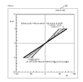
- FIG. 21 is a diagram showing one example of control logical formulas ⁇ 1 (e 0 , ⁇ u 0 ) and ⁇ 2 (e 0 , ⁇ u 0 ) which are created respectively in respect of control specifications 1 and 2 ;
- FIG. 22 is a diagram showing one example of the operation of a control device provided with a control logical formula ⁇ 1 (e 0 , ⁇ u 0 );
- FIG. 23 is a diagram showing one example of the operation of a control device provided with a control logical formula ⁇ 2 (e 0 , ⁇ u 0 );
- FIG. 24 is a block diagram showing a configuration of a control device provided with a control logical formula which is generated by the control system design assist device;
- FIG. 25 is a block diagram showing a configuration of a control device provided with a control logical formula which is generated by the control system design assist device.
- FIG. 26 is a block diagram showing a configuration of a control device provided with a control logical formula which is generated by the control system design assist device.
- control system design assist device according to one embodiment of the present disclosure is described with reference to FIG. 1 and FIG. 2 .
- FIG. 3 illustrates the relationship between a control amount, a control amount variation value, an operation amount and an operation change amount which are used in the following description.
- the control amount Y is the output of the control object, which is measured by a meter, such as a sensor, and is an amount that is controlled so as to become a set target value r (dash line).
- the operation amount u is the output of the controller, and is an amount of operation performed in order for the control amount Y to follow the target value r.
- the control system design assist device 1 shown in FIG. 1 is a device for assisting the design of a control system which controls a control amount Y of a control object, to a target value r, and is configured including a control logical formula generation unit 100 , a display unit 107 and a storage unit 108 .
- Control specifications and a control response waveform are stored in the storage unit 108 . Furthermore, the control specifications include the evaluation timing, the operation change amount upper and lower limits and the permitted target deviation.
- FIG. 4 shows one example of these control specifications and a control response waveform.
- the evaluation timings are made up of a sequence of control timings ti and a sequence of operation timings sj.
- the operation change amount upper and lower limits are constraint conditions for the operation change amount ⁇ u(sj) at each operation timing sj, and are expressed as in Formula (1) below.
- Lj and ⁇ Lj are the upper limit value and lower limit value of the operation change amount ⁇ u(sj) at each operation timing sj.
- the permitted target deviation is a constraint condition for the target deviation e(ti) at each control timing ti, and is expressed as shown in Formula (2) below.
- ai and ⁇ ai are the upper limit value and lower limit value of the ratio e(ti)/
- the upper limit value ai and the lower limit value ⁇ ai at each control timing ti are stored in the storage unit 108 .
- the control response waveform is a response waveform of the control amount Y when the operation amount u of the control object is changed.
- time series data of the control amount variation value y in other words, the response waveform after shaping the target value, which is input to the control object via a target value shaping filter, such as a reference governor.
- the control logical formula generation unit 100 is configured including a response prediction formula generation unit 101 , an evaluation formula generation unit 102 , a first-order predicate logical formula conversion unit 103 , and a quantifier eliminating unit 104 .
- a control response waveform and evaluation timing are input to the response prediction formula generation unit 101 , and the response prediction formula generation unit 101 outputs a response prediction formula.
- the response prediction formula, the operation change amount upper and lower limits, and the permitted target deviation are input to the evaluation formula generation unit 102 , and the evaluation formula generation unit 102 outputs an evaluation formula.
- the evaluation formula is input to the first-order predicate logical formula conversion unit 103 , and the first-order predicate logical formula conversion unit 103 outputs a first-order predicate logical formula.
- the first-order predicate logical formula is input to the quantifier eliminating unit 104 , and the quantifier eliminating unit 104 outputs a control logical formula.
- the control logical formula is input to the display unit 107 from the quantifier eliminating unit 104 of the control logical formula generation unit 100 .
- the display unit 107 then displays the control logical formula on a graph.
- the control system design assist device 1 shown in FIG. 1 can be constructed on a computer system such as that shown in FIG. 2 .
- the control system design assist device 1 shown in FIG. 2 is configured including a response prediction formula generation unit 101 , an evaluation formula generation unit 102 , a first-order predicate logical formula conversion unit 103 , a quantifier eliminating unit 104 , an input unit 106 , an output unit (display unit) 107 and a storage device 108 , which are interconnected with one another via a bus 109 .
- the functions of the control system design assist device 1 can be realized by a computer (control logical formula generation unit) 100 which is provided with the input unit 106 , the output unit 107 , the storage unit 108 and the bus 109 .
- control system design assist device according to a present embodiment is described with reference to FIG. 5 through FIG. 18 , as appropriate.
- the assistance in the design of a control system performed by the control system design assist device 1 involves: a response prediction formula generation process performed by the response prediction formula generation unit 101 , an evaluation formula generation process performed by the evaluation formula generation unit 102 , a first-order predicate logical formula conversion process performed by the first-order predicate logical formula conversion unit 103 , a quantifier elimination process performed by the quantifier eliminating unit 104 , and a display process performed by the display unit 107 .
- the functions of the control system design assist device 1 can be achieved by the computer 100 .
- the response prediction formula generation process, evaluation formula generation process, first-order predicate logical formula conversion process, quantifier elimination process and display process can be achieved by executing a control system design assist program in the computer 100 .
- the computer 100 may execute the control system design assist program by reading out a control system design assist program stored on a storage medium, such as a CD-ROM or DVD, etc. which is configured so as to be readable by the computer 100 , or may acquire the control system design assist program from another computer (not illustrated) which is connected communicably and execute the same.
- a response prediction formula is generated on the basis of a control response waveform and an evaluation timing (control timing ti; operation timing sj).
- a first evaluation formula Model a second evaluation formula Rst, and a third evaluation formula Obj, which correspond respectively to the response prediction formula, the operation change amount upper and lower limits, and the permitted target deviation, are generated on the basis thereof.
- the first evaluation formula Model is a formula which expresses the target deviation e(ti) at each control timing ti as a logical formula, and this logical formula expresses a prediction model for control. More specifically, the first evaluation formula Model is expressed as indicated in Formula (4) below, on the basis of the response prediction formula and the current value e 0 of the target deviation.
- the second evaluation formula Rst is a formula which expresses the operation change amount upper and lower limits which are expressed as indicated in Formula (1) above, as a logical formula, and this logical formula expresses a constraint condition for the operation change amount ⁇ u(sj) at each operation timing sj. More specifically, the second evaluation formula Rst is expressed as indicated in Formula (5) below.
- the third evaluation formula Obj is a formula which expresses the permitted target deviation that is expressed as indicated in Formula (2) above, as a logical formula, and this logical formula expresses a constraint condition for the target deviation e(ti) at each control timing ti. More specifically, the third evaluation formula Obj is expressed as indicated in Formula (6) below, by removing the absolute value terms in Formula (2).
- a logical product is obtained by joining the first evaluation formula Model, the second evaluation formula Rst, and the third evaluation formula Obj in use of the connective ( ), and converting the same to a first-order predicate logical formula by attaching a quantifier to a portion of the variables.
- a logical product is obtained by joining the first evaluation formula Model, the second evaluation formula Rst, and the third evaluation formula Obj in use of the connective ( ), and converting the same to a first-order predicate logical formula by attaching a quantifier to a portion of the variables.
- a formula which finds the logical product of the first to third evaluation formulas (Model Rst Obj) is converted into a (first) first-order predicate logical formula ⁇ in which the existential quantifier ( ⁇ ) is attached to the variables apart from the current value e 0 of the target deviation and the operation change amount ⁇ u(s 0 ) at the first operation timing s 0 .
- the first-order predicate logical formula ⁇ is expressed as indicated by Formula (7) below, by attaching the existential qualifier ( ⁇ ) to the variables ⁇ u(s 1 ), . . . , ⁇ u(sm), y(t 1 ), . . . , y(tn), e(t 1 ), . . . , e(tn), in the formula (Model ⁇ Rst ⁇ Obj).
- the variables to which the existential quantifier ( ⁇ ) has been attached in the first-order predicate logical formula ⁇ are eliminated to generate a logically equivalent control logical formula.
- a control logical formula ⁇ (e 0 , ⁇ u 0 ) indicating the relationship between the current value e 0 of the target deviation and the operation change amount ⁇ u 0 ⁇ u(s 0 ) at the operation timing s 0 is generated.
- a commonly known algorithm, such as the QE (Quantifier Elimination) algorithm in Non-Patent Document 5, for example, can be used for the quantifier elimination process.
- FIG. 9 shows an example of a graph which is displayed on the display unit 107 on the basis of the example of the control logical formula ⁇ (e 0 , ⁇ u 0 ) shown in FIG. 8 .
- a control logical formula of this kind can be created easily by using a computer, or the like, to select one point other than the point of origin contained in the region of the control logical formula ⁇ (e 0 , ⁇ u 0 ), and creating the control logical formula on the basis of a first-order function (straight line) passing through that point and the point of origin, and the constraint condition for the operation change amount ⁇ u 0 .
- FIG. 11 shows an example in which the region of the control logical formula which satisfies control specifications 1 and the region of the control logical formula which satisfies control specifications 2 are displayed on the same graph. When the control specifications 2 are satisfied, then the control specifications 1 are always satisfied as well, and therefore in FIG. 11 , the region of the control specifications 2 is a portion of the region of the control specifications 1 .
- control system design assist device 1 may generate control logical formulas using control specifications such as those shown in FIG. 12 , for example, (called control specifications 3 below), and may display these control logical formulas on the graph.
- the approach to the permitted target deviation is different to that in the control specifications 1 and/or the control specifications 2 . More specifically, in the case of the control specifications 1 and/or control specifications 2 , the permitted target deviation is defined on the basis of the absolute value
- the permitted target deviation is defined in such a manner that the value of the target deviation e(ti) at each control timing ti is made smaller, while still having a positive value.
- the permitted target deviation is defined in such a manner that the value of the target deviation e(ti) at each control timing ti is made smaller, while still having a negative value.
- the permitted target deviation in the control specifications 3 is expressed as indicated in Formulas (9) and (10) below, for example.
- e(ti) when the sign of e 0 is positive, then e(ti) can be limited to a positive region in the range where ⁇ ia , ⁇ ib , e 0 are positive, and when the sign of e 0 is negative, then e(ti) can be limited to a negative region in the range where ⁇ ia , ⁇ ib are positive and e 0 is negative.
- FIG. 13 shows the evaluation formula which is generated by the evaluation formula generation unit 102 when the control specifications 3 are used.
- the first evaluation formula Model and the second evaluation formula Rst are the same as the control specifications 1 and the control specifications 2 , but the third evaluation formula Obj is different.
- control specifications 3 when the control specifications 3 are used, the contents of the processing carried out by the first-order predicate logical formula conversion unit 103 and the quantifier eliminating unit 104 are similar to the control specifications 1 and/or the control specifications 2 .
- FIG. 14 shows a situation where the graph of the control logical formula ⁇ (e 0 , ⁇ u 0 ) of the control specifications 3 which is generated in this way is displayed by the display unit 107 .
- FIG. 15 shows an example in which the regions of the control logical formulas that satisfy the control specifications 1 , the control specifications 2 and the control specifications 3 are displayed on the same graph.
- the display unit 107 may further display a graph other than a control logical formula ⁇ (e 0 , ⁇ u 0 ) indicating the relationship between the current value e 0 of the target deviation and the operation change amount ⁇ u 0 .
- a control logical formula ⁇ (e 0 , ⁇ u 0 ) indicating the relationship between the current value e 0 of the target deviation and the operation change amount ⁇ u 0 .
- FIG. 16 through FIG. 18 show examples of a method wherein a logical formula ⁇ ′( ⁇ u 0 , ⁇ u 1 ) indicating a relationship between the operation change amount ⁇ u 0 at the operation timing s 0 and the operation change amount ⁇ u 1 ⁇ u(s 1 ) at the operation timing s 1 is generated and a graph thereof is used in designing a control system.
- FIG. 16 indicates that a range where the operation change amount ⁇ u 0 is MIN 0 ⁇ u 0 ⁇ MAX 0 can be obtained when the current value e 0 of the target deviation is fixed to a particular value (for example, 30), but does not indicate the relationship with other variables.
- a particular value for example, 30
- a logical formula ⁇ ′( ⁇ u 0 , ⁇ u 1 ) indicating the relationship between the operation change amount ⁇ u 0 and the operation change amount ⁇ u 1 is generated by a first-order predicate logical formula conversion process performed by the first-order predicate logical formula conversion unit 103 and a quantifier elimination process performed by the quantifier eliminating unit 104 .
- a formula deriving the logical product of the first to third evaluation formulas (Model ⁇ RSt ⁇ Obj) is converted to a (second) first-order predicate logical formula ⁇ ′, which is different to the (first) first-order predicate logical formula ⁇ .
- FIG. 18 shows a graph of the region where the logical formula ⁇ ′( ⁇ u 0 , ⁇ u 1 ) is established, which is displayed on the display unit 107 in addition to the graph of the control logical formula ⁇ (e 0 , ⁇ u 0 ).
- control device 2 which is provided with a control logical formula generated by the control system design assist device 1 will be described with reference to FIG. 19 .
- the control device 2 illustrated in FIG. 19 is a device for controlling a control amount Y of a control object 9 to a target value r, and is configured including a timer 201 , a measurement unit 202 , a target deviation calculation unit 203 , an operation change amount calculation unit 204 and an operation amount updating unit 205 .
- the timer 201 receives input of a control cycle Tc, and the measurement unit 202 and the operation change amount calculation unit 204 operate at each control cycle Tc, under the control of the timer 201 . Furthermore, the measurement unit 202 receives the input of the operation amount u and the control amount Y of the control object, and the measurement unit 202 outputs the measurement value (current value) u 0 of the operation amount and the measurement value (current value) Y 0 of the control amount. Moreover, the target deviation calculation unit 203 receives input of the measurement value Y 0 of the control amount and the target value r thereof, and the target deviation calculation unit 203 outputs the current value e 0 of the target deviation.
- the operation change amount calculation unit 204 is provided with a control logical formula ⁇ (e 0 , ⁇ u 0 ) generated by the control system design assist device 1 . Furthermore, the operation change amount calculation unit 204 receives input of the current value e 0 of the target deviation, and the operation change amount calculation unit 204 outputs the next operation change amount ⁇ u 0 (for operation timing s 0 ). The operation amount updating unit 205 receives input of the measurement value u 0 of the operation amount and the operation change amount ⁇ u 0 , and outputs an operation amount u.
- control device 2 is described with reference to FIG. 20 to FIG. 23 , as appropriate.
- the measurement unit 202 measures the operation amount u and the control amount Y, at each control cycle Tc, and outputs the respective measurement values u 0 and Y 0 . Furthermore, the target deviation calculation unit 203 subtracts the measurement value Y 0 of the control amount, from the target value r, and calculates the current value e 0 of the target deviation. Moreover, the operation change amount calculation unit 204 calculates the operation change amount ⁇ u 0 , on the basis of the control logical formula ⁇ (e 0 , ⁇ u 0 ) and the current value e 0 of the target deviation, at each control cycle Tc. FIG. 20 shows the operation of the operation change amount calculation unit 204 at each control cycle.
- the current value e 0 of the target deviation is acquired (S 1 ).
- the current value e 0 of the target deviation is substituted into the control logical formula ⁇ (e 0 , ⁇ u 0 ), and a logical formula ⁇ u( ⁇ u 0 ) relating only to the operation change amount ⁇ u 0 is generated (S 2 ).
- a candidate ⁇ u 0 * for the operation change amount that is established by the logical formula ⁇ u( ⁇ u 0 ) is searched for (S 3 ). For example, values are substituted into the logical formula ⁇ u( ⁇ u 0 ), while successively increasing or decreasing from a prescribed initial value, in prescribed steps, and are determined to be true or false, and the first value which is determined to be true is set as a candidate ⁇ u 0 * for the operation change amount. Furthermore, for instance, a candidate ⁇ u 0 * for the operation change amount may also be searched for by performing a binary search from a prescribed initial value.
- the operation amount updating unit 205 updates the operation amount u by adding the operation change amount ⁇ u 0 to the measurement value u 0 of the operation amount. In this way, an updated operation amount u is output at each control cycle Tc, on the basis of the control logical formula ⁇ (e 0 , ⁇ u 0 ), from the control device 2 .
- control logical formula ⁇ (e 0 , ⁇ u 0 ) instead of using the control logical formula ⁇ (e 0 , ⁇ u 0 ) directly, it is also possible to create and use a simpler control logical formula, in the plotted range of the region of the control logical formula ⁇ (e 0 , ⁇ u 0 ).
- FIG. 21 shows one example of a control logical formula including a first-order function passing through the point of origin and a constraint condition for the operation change amount ⁇ u 0 , which is newly created within the range of the region of the control logical formula that satisfies the respective control specifications, in respect of the abovementioned control specifications 1 and 2 .
- a control logical formula ⁇ 1 (e 0 , ⁇ u 0 ) which is indicated by Formula (11) below is created in respect of the control specifications 1.
- FIG. 22 and FIG. 23 respectively show concrete examples of the operation of a control device 2 which is provided with the control logical formula ⁇ 1 (e 0 , ⁇ u 0 ) and the control logical formula ⁇ 2 (e 0 , ⁇ u 0 ).
- the first equation in the logical formula ⁇ u 1 ( ⁇ u 0 ) is determined to be true within a range of error of ⁇ 0.2, in respect of the 0.1 step width.
- control logical formula that is generated by the control system design assist device 1 according to the present embodiment can be applied to control devices 2 of various configurations, such as those shown in FIG. 24 through FIG. 26 .
- control device 2 shown in FIG. 24 is an example of a case where a feed-forward controller 206 is provided in the control device 2 shown in FIG. 19 .
- the feed-forward controller 206 calculates and outputs a feed-forward correction amount of corresponding to the operation amount u, on the basis of the target value r.
- the operation amount u output from the control device 2 and the feed-forward correction amount uf are combined in the adder 207 and then input to the control object 9 .
- control device 2 shown in FIG. 25 is an example of a case where a filter circuit 208 is provided in the control device 2 shown in FIG. 19 .
- the filter circuit 208 applies a prescribed filtering process to the target value r input to the control device 2 so as to achieve a smooth amount of change per unit time (rate of change) (for example, a moving average of the target value r for a prescribed time period in the past is calculated), and inputs the result to the target deviation calculation unit 203 .
- a smooth amount of change per unit time for example, a moving average of the target value r for a prescribed time period in the past is calculated
- control device 2 shown in FIG. 26 is an example of a case where a Smith compensator 209 is provided in the control device 2 shown in FIG. 19 .
- the Smith compensator 209 is effective in improving control performance by returning the compensation amount to the control loop as positive feedback, and expelling waste time elements from the control loop when the control object 9 includes the elements of waste of time in operation, as described, for example, in Hashimoto, Hasebe, Kano, “Process Control Engineering”, Asakura Publishing Co., Ltd., 2002, p. 99.
- the target deviation calculation unit 203 Since the compensation amount calculated from the operation amount u by the Smith compensator 209 is provided as positive feedback, then when outputting the current value e 0 of the target deviation by subtracting the measurement value Y 0 of the control amount from the target value r, the target deviation calculation unit 203 also subtracts the compensation amount calculated by the Smith compensator 209 .
- control logical formula calculated by the control system design assist device 1 according to the present embodiment can be used in various control devices 2 . Therefore, it is also possible to control the control object 9 with greater accuracy, by using the abovementioned control logical formula in a control device 2 which is configured as appropriate in accordance with the characteristics of the control object 9 , for instance.
- a control device 2 which is configured as appropriate in accordance with the characteristics of the control object 9 may be, for example, a control device 2 which includes at least one of the abovementioned feed-forward controller 206 , filter circuit 208 and Smith compensator 209 , or the like.
- the logical product (Model ⁇ Rst ⁇ Obj) of the evaluation formulas Model, Rst, Obj generated from the control specifications and the control response waveform is converted into a (first) first-order predicate logical formula ⁇ , and a control logical formula ⁇ (e 0 , ⁇ u 0 ) indicating the relationship between the current value e 0 of the target deviation and the next operation change amount ⁇ u 0 is generated by a quantifier elimination process, and is displayed on a graph, thereby providing a visual depiction of the region of the (e 0 , ⁇ u 0 ) coordinates system which satisfies the control specifications.
- a designer can use this control logical formula ⁇ (e 0 , ⁇ u 0 ) to design a control system that improves control performance that takes account of time response, such as inverse response, and furthermore, a more simple (less expensive) control logical formula can be created and used within the plotted range of the region of the control logical formula ⁇ (e 0 , ⁇ u 0 ).
- control device 2 by calculating the operation change amount ⁇ u 0 on the basis of the control logical formula ⁇ (e 0 , ⁇ u 0 ) generated by the control system design assist device 1 and the current value e 0 of the target deviation, at each control cycle Tc, and outputting the updated operation amount u, it is possible to improve the control performance that takes account of time response, such as inverse response, and furthermore, by creating and using a more simple control logical formula within the plotted range of the region of the control logical formula ⁇ (e 0 , ⁇ u 0 ), it is possible to improve the control performance that takes account of time response, at lower cost.
- all units or components that perform calculation, control, computing and/or data processing functionalities may be implemented in the form of at least one hardware processor configured to perform these functionalities. That is, the performance of any one or more of the functionalities may be accomplished by a single hardware processor, or be divided, in any manner known to those skilled in the art, among multiple hardware processors.
Landscapes
- Engineering & Computer Science (AREA)
- Physics & Mathematics (AREA)
- General Physics & Mathematics (AREA)
- Theoretical Computer Science (AREA)
- Data Mining & Analysis (AREA)
- Pure & Applied Mathematics (AREA)
- Mathematical Physics (AREA)
- Mathematical Optimization (AREA)
- Mathematical Analysis (AREA)
- Computational Mathematics (AREA)
- General Engineering & Computer Science (AREA)
- Automation & Control Theory (AREA)
- Software Systems (AREA)
- Probability & Statistics with Applications (AREA)
- Evolutionary Biology (AREA)
- Bioinformatics & Computational Biology (AREA)
- Bioinformatics & Cheminformatics (AREA)
- Operations Research (AREA)
- Life Sciences & Earth Sciences (AREA)
- Algebra (AREA)
- Databases & Information Systems (AREA)
- Geometry (AREA)
- Evolutionary Computation (AREA)
- Computer Hardware Design (AREA)
- Feedback Control In General (AREA)
- Architecture (AREA)
Abstract
Description
−Lj≤Δu(sj)≤Lj (1)
−ai·|e0|≤e(ti)≤ai·|e0| (2)
αib e0≤e(ti)≤αia e0(e0≥0,αia≥αib≥0,i=1,2 . . . ) (9)
[Expression 10]
αia e0≤e(ti)≤αib e0(e0≤0,αia≥αib≥0,i=1,2 . . . ) (10)
ϕ1(e0,Δu0):=48Δu0−5e0=0
ϕ2(e0,Δu0):=15Δu0−e0=0
ϕu1(Δu0):=48Δu0−5=0
is derived, and since the candidate Δu0*=0.1 for the operation change amount by which the logical formula Δu1(Δu0) is established is found, then the operation change amount Δu0=Δu0*=0.1 is output. The first equation in the logical formula ϕu1(Δu0) is determined to be true within a range of error of ±0.2, in respect of the 0.1 step width. The updated operation amount u=u0+Δu0=0.1 is output at timing t=2. Thereafter, in a similar fashion, an updated operation amount u is output each time the control cycle Tc=6, and the control amount Y converges to the target value r.
- 1 control system design assist device
- 2 control device
- 9 control object
- 100 control logical formula generation unit (computer)
- 101 response prediction formula generation unit
- 102 evaluation formula generation unit
- 103 first-order predicate logical formula conversion unit
- 104 quantifier eliminating unit
- 106 input unit
- 107 display unit (output unit)
- 108 storage unit
- 109 bus
- 201 timer
- 202 measurement unit
- 203 target deviation calculation unit
- 204 operation change amount calculation unit
- 205 operation amount updating unit
- 206 feed-forward controller
- 207 adder
- 208 filter circuit
- 209 Smith compensator
- 300 storage medium
Claims (10)
Applications Claiming Priority (3)
| Application Number | Priority Date | Filing Date | Title |
|---|---|---|---|
| JP2013-218092 | 2013-10-21 | ||
| JP2013218092 | 2013-10-21 | ||
| PCT/JP2014/077221 WO2015060149A1 (en) | 2013-10-21 | 2014-10-10 | Control system design assist device, control system design assist program, control system design assist method, operation change amount calculation device, and control device |
Related Parent Applications (1)
| Application Number | Title | Priority Date | Filing Date |
|---|---|---|---|
| PCT/JP2014/077221 Continuation WO2015060149A1 (en) | 2013-10-21 | 2014-10-10 | Control system design assist device, control system design assist program, control system design assist method, operation change amount calculation device, and control device |
Publications (2)
| Publication Number | Publication Date |
|---|---|
| US20160063142A1 US20160063142A1 (en) | 2016-03-03 |
| US10068035B2 true US10068035B2 (en) | 2018-09-04 |
Family
ID=52992749
Family Applications (1)
| Application Number | Title | Priority Date | Filing Date |
|---|---|---|---|
| US14/936,981 Active 2036-03-28 US10068035B2 (en) | 2013-10-21 | 2015-11-10 | Control system design assist device, control system design assist program, control system design assist method, operation change amount calculation device and control device |
Country Status (4)
| Country | Link |
|---|---|
| US (1) | US10068035B2 (en) |
| EP (1) | EP3062175B1 (en) |
| JP (1) | JP5994947B2 (en) |
| WO (1) | WO2015060149A1 (en) |
Families Citing this family (6)
| Publication number | Priority date | Publication date | Assignee | Title |
|---|---|---|---|---|
| US11922314B1 (en) * | 2018-11-30 | 2024-03-05 | Ansys, Inc. | Systems and methods for building dynamic reduced order physical models |
| JP2020091611A (en) * | 2018-12-04 | 2020-06-11 | 富士通株式会社 | Action determination program, action determination method, and action determination device |
| JP7206874B2 (en) * | 2018-12-10 | 2023-01-18 | 富士電機株式会社 | Control device, control method and program |
| JP2020095586A (en) * | 2018-12-14 | 2020-06-18 | 富士通株式会社 | Reinforcement learning method and reinforcement learning program |
| US11741375B2 (en) | 2019-11-15 | 2023-08-29 | International Business Machines Corporation | Capturing the global structure of logical formulae with graph long short-term memory |
| JP6901037B1 (en) * | 2020-12-18 | 2021-07-14 | 富士電機株式会社 | Control devices, control methods and programs |
Citations (8)
| Publication number | Priority date | Publication date | Assignee | Title |
|---|---|---|---|---|
| US5347446A (en) | 1991-02-08 | 1994-09-13 | Kabushiki Kaisha Toshiba | Model predictive control apparatus |
| JPH0883104A (en) | 1994-09-12 | 1996-03-26 | Toshiba Corp | Plant control equipment |
| JPH11201435A (en) | 1998-01-19 | 1999-07-30 | Hitachi Ltd | Waste incineration power plant and its load control method |
| JPH11328239A (en) | 1998-05-13 | 1999-11-30 | Fujitsu Ltd | Control system analysis / design device and control system analysis / design processing method |
| US6081751A (en) * | 1997-12-19 | 2000-06-27 | National Instruments Corporation | System and method for closed loop autotuning of PID controllers |
| JP2004038618A (en) | 2002-07-04 | 2004-02-05 | Fujitsu Ltd | Pole layout analysis / design method for control system, pole layout analysis / design equipment, pole layout analysis / design program |
| US20060224255A1 (en) * | 2003-08-21 | 2006-10-05 | Masato Tanaka | Pid parameter adjustment device |
| JP2007170814A (en) | 2007-03-19 | 2007-07-05 | Meidensha Corp | Water level control device for boiler drum |
Family Cites Families (2)
| Publication number | Priority date | Publication date | Assignee | Title |
|---|---|---|---|---|
| DE3872213T2 (en) | 1988-02-05 | 1993-01-28 | Merrell Dow Pharma | 5-SUBSTITUTED ORNITHIN DERIVATIVES. |
| JP3135238B2 (en) | 1989-06-26 | 2001-02-13 | 株式会社ジェイ エス ピー | Olefin resin pre-expanded particles |
-
2014
- 2014-10-10 JP JP2015543797A patent/JP5994947B2/en active Active
- 2014-10-10 WO PCT/JP2014/077221 patent/WO2015060149A1/en not_active Ceased
- 2014-10-10 EP EP14856365.3A patent/EP3062175B1/en active Active
-
2015
- 2015-11-10 US US14/936,981 patent/US10068035B2/en active Active
Patent Citations (8)
| Publication number | Priority date | Publication date | Assignee | Title |
|---|---|---|---|---|
| US5347446A (en) | 1991-02-08 | 1994-09-13 | Kabushiki Kaisha Toshiba | Model predictive control apparatus |
| JPH0883104A (en) | 1994-09-12 | 1996-03-26 | Toshiba Corp | Plant control equipment |
| US6081751A (en) * | 1997-12-19 | 2000-06-27 | National Instruments Corporation | System and method for closed loop autotuning of PID controllers |
| JPH11201435A (en) | 1998-01-19 | 1999-07-30 | Hitachi Ltd | Waste incineration power plant and its load control method |
| JPH11328239A (en) | 1998-05-13 | 1999-11-30 | Fujitsu Ltd | Control system analysis / design device and control system analysis / design processing method |
| JP2004038618A (en) | 2002-07-04 | 2004-02-05 | Fujitsu Ltd | Pole layout analysis / design method for control system, pole layout analysis / design equipment, pole layout analysis / design program |
| US20060224255A1 (en) * | 2003-08-21 | 2006-10-05 | Masato Tanaka | Pid parameter adjustment device |
| JP2007170814A (en) | 2007-03-19 | 2007-07-05 | Meidensha Corp | Water level control device for boiler drum |
Non-Patent Citations (9)
| Title |
|---|
| C. C. Hang et al., "A Comparison of Two Design Methods for PID Controllers", Advances in Instrumentation and Control, vol. 48, Instrument Society of America, 1993, pp. 959-967. |
| C. Garcia et al. "Quadratic Programming Solution of Dynamic Matrix Control (DMC)", Chemical Engineering Communications, Gordon and Breach Science Publishers S.A., vol. 46, pp. 73-87, 1986. |
| C. Garcia et al. "Quadratic Programming Solution of Dynamic Matrix Control (QDMC)", Chemical Engineering Communications, Gordon and Breach Science Publishers S.A., vol. 46, pp. 73-87, 1986. |
| Extended European Search Report dated Apr. 10, 2017 in corresponding European Patent Application 14856365.3. |
| H. Anai, "Parametric Robust Control Toolbox by Quantifier Elimination", Journal of the Japan Society of Simulation Technology, Mar. 15, 2006, vol. 25, No. 1, pp. 53-61. |
| Hirokazu Anai et al., "Parametric Robust Control by Quantifier Elimination", Japan Society for Symbolic and Algebraic Computation vol. 10, No. 1, Aug. 1, 2003, pp. 41-51. |
| International Search Report dated Jan. 13, 2015, in corresponding International Application No. PCT/JP2014/077221. |
| T. Fujiwara, "Tuning Method "K/s" of PID Controller also Applicable to Inverse Response characteristics", 1996, vol. 9, No. 11, pp. 495-502. |
| Wang Zhenwei et al., "An intelligent modeling and analysis method of manufacturing process using the first-order predicate logic", Computers & Industrial Engineering, vol. 56, No. 4, Elsevier, May 1, 2009, pp. 1559-1565. |
Also Published As
| Publication number | Publication date |
|---|---|
| JPWO2015060149A1 (en) | 2017-03-09 |
| WO2015060149A1 (en) | 2015-04-30 |
| EP3062175A4 (en) | 2017-05-10 |
| JP5994947B2 (en) | 2016-09-21 |
| EP3062175A1 (en) | 2016-08-31 |
| EP3062175B1 (en) | 2018-09-05 |
| US20160063142A1 (en) | 2016-03-03 |
Similar Documents
| Publication | Publication Date | Title |
|---|---|---|
| US10068035B2 (en) | Control system design assist device, control system design assist program, control system design assist method, operation change amount calculation device and control device | |
| Wabersich et al. | Probabilistic model predictive safety certification for learning-based control | |
| Yang et al. | Advanced-multi-step nonlinear model predictive control | |
| Sandee et al. | Event-driven control as an opportunity in the multidisciplinary development of embedded controllers. | |
| JP6380552B2 (en) | Control device, program thereof, and plant control method | |
| US20150309486A1 (en) | Engineering Tool and Method for Parameterizing a Model-Based Predictive Controller | |
| Veselý et al. | Robust model predictive control design with input constraints | |
| Kungurtsev et al. | A predictor-corrector path-following algorithm for dual-degenerate parametric optimization problems | |
| WO2019176647A1 (en) | Continuous optimization problem global searching device and program | |
| Furtat | Adaptive predictor-free control of a plant with delayed input signal | |
| Leeman et al. | Fast system level synthesis: Robust model predictive control using Riccati recursions | |
| Paternain et al. | A prediction-correction method for model predictive control | |
| JP7077667B2 (en) | Control method, control device and program | |
| JP6222234B2 (en) | Control apparatus and control method | |
| Peccin et al. | Fast generalized predictive control based on accelerated dual gradient projection method | |
| JP7283095B2 (en) | Control device, control method and program | |
| JP2014191736A (en) | Control parameter determination device, method, and program, and controller, and optimization control system | |
| US9015095B2 (en) | Neural network designing method and digital-to-analog fitting method | |
| Rubagotti et al. | Stabilizing embedded MPC with computational complexity guarantees | |
| KR101593038B1 (en) | Method for predictive control using quadratic programming | |
| Aguiar et al. | An LMI-based global non-quadratic observer design via Takagi-Sugeno models and Levant's robust differentiators | |
| Tange et al. | Overshoot suppression control based on final tracking error estimation and quantifier elimination | |
| Nahri et al. | A comparative study on time-delay estimation for time-delay nonlinear system control. | |
| CN111694279A (en) | Multi-variable nonlinear system self-adaptive balanced multi-model decomposition and control method | |
| Cyrus et al. | A Revised Mehrotra Predictor-Corrector algorithm for Model Predictive Control |
Legal Events
| Date | Code | Title | Description |
|---|---|---|---|
| AS | Assignment |
Owner name: FUJI ELECTRIC CO., LTD., JAPAN Free format text: ASSIGNMENT OF ASSIGNORS INTEREST;ASSIGNOR:TANGE, YOSHIO;REEL/FRAME:037014/0970 Effective date: 20151020 |
|
| STCF | Information on status: patent grant |
Free format text: PATENTED CASE |
|
| CC | Certificate of correction | ||
| MAFP | Maintenance fee payment |
Free format text: PAYMENT OF MAINTENANCE FEE, 4TH YEAR, LARGE ENTITY (ORIGINAL EVENT CODE: M1551); ENTITY STATUS OF PATENT OWNER: LARGE ENTITY Year of fee payment: 4 |
|
| MAFP | Maintenance fee payment |
Free format text: PAYMENT OF MAINTENANCE FEE, 8TH YEAR, LARGE ENTITY (ORIGINAL EVENT CODE: M1552); ENTITY STATUS OF PATENT OWNER: LARGE ENTITY Year of fee payment: 8 |