US10067462B2 - Developer container, developer unit and image forming apparatus - Google Patents
Developer container, developer unit and image forming apparatus Download PDFInfo
- Publication number
- US10067462B2 US10067462B2 US15/464,132 US201715464132A US10067462B2 US 10067462 B2 US10067462 B2 US 10067462B2 US 201715464132 A US201715464132 A US 201715464132A US 10067462 B2 US10067462 B2 US 10067462B2
- Authority
- US
- United States
- Prior art keywords
- marker
- memory device
- image forming
- developer container
- holding member
- Prior art date
- Legal status (The legal status is an assumption and is not a legal conclusion. Google has not performed a legal analysis and makes no representation as to the accuracy of the status listed.)
- Active, expires
Links
Images


Classifications
-
- G—PHYSICS
- G03—PHOTOGRAPHY; CINEMATOGRAPHY; ANALOGOUS TECHNIQUES USING WAVES OTHER THAN OPTICAL WAVES; ELECTROGRAPHY; HOLOGRAPHY
- G03G—ELECTROGRAPHY; ELECTROPHOTOGRAPHY; MAGNETOGRAPHY
- G03G21/00—Arrangements not provided for by groups G03G13/00 - G03G19/00, e.g. cleaning, elimination of residual charge
- G03G21/16—Mechanical means for facilitating the maintenance of the apparatus, e.g. modular arrangements
- G03G21/1642—Mechanical means for facilitating the maintenance of the apparatus, e.g. modular arrangements for connecting the different parts of the apparatus
- G03G21/1652—Electrical connection means
-
- G—PHYSICS
- G03—PHOTOGRAPHY; CINEMATOGRAPHY; ANALOGOUS TECHNIQUES USING WAVES OTHER THAN OPTICAL WAVES; ELECTROGRAPHY; HOLOGRAPHY
- G03G—ELECTROGRAPHY; ELECTROPHOTOGRAPHY; MAGNETOGRAPHY
- G03G15/00—Apparatus for electrographic processes using a charge pattern
- G03G15/06—Apparatus for electrographic processes using a charge pattern for developing
- G03G15/08—Apparatus for electrographic processes using a charge pattern for developing using a solid developer, e.g. powder developer
- G03G15/0822—Arrangements for preparing, mixing, supplying or dispensing developer
- G03G15/0863—Arrangements for preparing, mixing, supplying or dispensing developer provided with identifying means or means for storing process- or use parameters, e.g. an electronic memory
-
- G—PHYSICS
- G03—PHOTOGRAPHY; CINEMATOGRAPHY; ANALOGOUS TECHNIQUES USING WAVES OTHER THAN OPTICAL WAVES; ELECTROGRAPHY; HOLOGRAPHY
- G03G—ELECTROGRAPHY; ELECTROPHOTOGRAPHY; MAGNETOGRAPHY
- G03G15/00—Apparatus for electrographic processes using a charge pattern
- G03G15/50—Machine control of apparatus for electrographic processes using a charge pattern, e.g. regulating differents parts of the machine, multimode copiers, microprocessor control
- G03G15/5066—Machine control of apparatus for electrographic processes using a charge pattern, e.g. regulating differents parts of the machine, multimode copiers, microprocessor control by using information from an external support, e.g. magnetic card
-
- G—PHYSICS
- G03—PHOTOGRAPHY; CINEMATOGRAPHY; ANALOGOUS TECHNIQUES USING WAVES OTHER THAN OPTICAL WAVES; ELECTROGRAPHY; HOLOGRAPHY
- G03G—ELECTROGRAPHY; ELECTROPHOTOGRAPHY; MAGNETOGRAPHY
- G03G21/00—Arrangements not provided for by groups G03G13/00 - G03G19/00, e.g. cleaning, elimination of residual charge
- G03G21/16—Mechanical means for facilitating the maintenance of the apparatus, e.g. modular arrangements
- G03G21/18—Mechanical means for facilitating the maintenance of the apparatus, e.g. modular arrangements using a processing cartridge, whereby the process cartridge comprises at least two image processing means in a single unit
- G03G21/1875—Mechanical means for facilitating the maintenance of the apparatus, e.g. modular arrangements using a processing cartridge, whereby the process cartridge comprises at least two image processing means in a single unit provided with identifying means or means for storing process- or use parameters, e.g. lifetime of the cartridge
- G03G21/1878—Electronically readable memory
- G03G21/1882—Electronically readable memory details of the communication with memory, e.g. wireless communication, protocols
- G03G21/1885—Electronically readable memory details of the communication with memory, e.g. wireless communication, protocols position of the memory; memory housings; electrodes
-
- G—PHYSICS
- G03—PHOTOGRAPHY; CINEMATOGRAPHY; ANALOGOUS TECHNIQUES USING WAVES OTHER THAN OPTICAL WAVES; ELECTROGRAPHY; HOLOGRAPHY
- G03G—ELECTROGRAPHY; ELECTROPHOTOGRAPHY; MAGNETOGRAPHY
- G03G21/00—Arrangements not provided for by groups G03G13/00 - G03G19/00, e.g. cleaning, elimination of residual charge
- G03G21/16—Mechanical means for facilitating the maintenance of the apparatus, e.g. modular arrangements
- G03G21/18—Mechanical means for facilitating the maintenance of the apparatus, e.g. modular arrangements using a processing cartridge, whereby the process cartridge comprises at least two image processing means in a single unit
- G03G21/1875—Mechanical means for facilitating the maintenance of the apparatus, e.g. modular arrangements using a processing cartridge, whereby the process cartridge comprises at least two image processing means in a single unit provided with identifying means or means for storing process- or use parameters, e.g. lifetime of the cartridge
- G03G21/1896—Mechanical means for facilitating the maintenance of the apparatus, e.g. modular arrangements using a processing cartridge, whereby the process cartridge comprises at least two image processing means in a single unit provided with identifying means or means for storing process- or use parameters, e.g. lifetime of the cartridge mechanical or optical identification means, e.g. protrusions, bar codes
-
- G—PHYSICS
- G03—PHOTOGRAPHY; CINEMATOGRAPHY; ANALOGOUS TECHNIQUES USING WAVES OTHER THAN OPTICAL WAVES; ELECTROGRAPHY; HOLOGRAPHY
- G03G—ELECTROGRAPHY; ELECTROPHOTOGRAPHY; MAGNETOGRAPHY
- G03G2215/00—Apparatus for electrophotographic processes
- G03G2215/01—Apparatus for electrophotographic processes for producing multicoloured copies
- G03G2215/0103—Plural electrographic recording members
- G03G2215/0119—Linear arrangement adjacent plural transfer points
- G03G2215/0138—Linear arrangement adjacent plural transfer points primary transfer to a recording medium carried by a transport belt
- G03G2215/0141—Linear arrangement adjacent plural transfer points primary transfer to a recording medium carried by a transport belt the linear arrangement being horizontal
-
- G—PHYSICS
- G03—PHOTOGRAPHY; CINEMATOGRAPHY; ANALOGOUS TECHNIQUES USING WAVES OTHER THAN OPTICAL WAVES; ELECTROGRAPHY; HOLOGRAPHY
- G03G—ELECTROGRAPHY; ELECTROPHOTOGRAPHY; MAGNETOGRAPHY
- G03G2215/00—Apparatus for electrophotographic processes
- G03G2215/06—Developing structures, details
- G03G2215/066—Toner cartridge or other attachable and detachable container for supplying developer material to replace the used material
- G03G2215/0695—Toner cartridge or other attachable and detachable container for supplying developer material to replace the used material using identification means or means for storing process or use parameters
- G03G2215/0697—Toner cartridge or other attachable and detachable container for supplying developer material to replace the used material using identification means or means for storing process or use parameters being an electronically readable memory
Definitions
- the present invention relates to a developer container, a development unit, an image carrier unit, an image forming unit, and an image forming apparatus.
- the applicant has already filed an application for a toner container in which a memory (information holding unit) is held by a frame and an image forming apparatus equipped with the container (for example, see Patent Document 1).
- the memory is configured to store information (e.g., color) on a toner to be accommodated in the toner container so that communication can be performed between the memory and, for example, a communication device provided in a main body of an image forming apparatus.
- Patent Doc. 1 JP Laid-Open Patent Publication 2007-199457
- a developer container includes a memory device with a first marker; and a main body with a second marker, the main body being configured to accommodate a developer.
- the memory device is attached to the main body such that both the first marker and the second marker are visually recognized.
- An image carrier unit includes a memory device with a first marker; a housing with a second marker, the housing being configured to accommodate an image carrier, a holding member that is configured to hold the memory device with respect to the housing such that both the first marker and the second marker are visually recognized.
- the memory device is to be held with respect to the housing or the main body such that both the first marker and the second marker are visually recognized. By visual inspection, the installation state of the memory device is easily determined.
- the developer container the developing unit, the image carrier unit, the image forming unit, and the image forming apparatus as an embodiment of the present disclosure, a user can easily confirm that the memory device is properly attached.
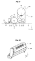
- FIG. 1 is a schematic diagram showing an overall configuration example of an image forming apparatus relating to one embodiment of the present invention.
- FIG. 2 is a schematic diagram showing an internal configuration of an image forming unit shown in FIG. 1 .
- FIG. 3A is a perspective view showing an external appearance of the image forming unit shown in FIG. 1 .
- FIG. 3B is an exploded perspective view showing an external appearance of the image forming unit shown in FIG. 1 .
- FIG. 4A is another perspective view showing an external appearance of the developer container shown in FIG. 1 .
- FIG. 4B is an enlarged exploded perspective view showing a main part of the developer container shown in FIG. 4A in an enlarged manner.
- FIG. 4C is a main part enlarged side view showing the main part of the developer container shown in FIG. 4A in an enlarged manner.
- FIG. 5A is a side view showing an external appearance of the developer container shown in FIG. 1 .
- FIG. 5B is a main part enlarged side view showing the main part of the developer container shown in FIG. 5A in an enlarged manner.
- FIG. 6A is a side view showing an external appearance of the developer container as a first modified example.
- FIG. 6B is a main part enlarged side view showing the main part of the developer container shown in FIG. 6A in an enlarged manner.
- FIG. 6C is another main part enlarged side view showing the main part of the developer container shown in FIG. 6A in an enlarged manner.
- FIG. 7A is a side view showing an external appearance of the developer container as a second modified example.
- FIG. 7B is a main part enlarged side view showing the main part of the developer container shown in FIG. 7A in an enlarged manner.
- FIG. 8A is a side view showing an external appearance of the developer container as a third modified example.
- FIG. 8B is a plan view showing a holding member as shown in FIG. 8A .
- FIG. 8C is a main part enlarged side view showing the main part of the developer container shown in FIG. 8A in an enlarged manner.
- FIG. 9A is a side view showing an external appearance of the developer container as a fourth modified example.
- FIG. 9B is a plan view showing a holding member shown in FIG. 9A .
- FIG. 9C is a main part enlarged side view showing a main part of the developer container shown in FIG. 9A in an enlarged manner.
- FIG. 9D is another main part enlarged side view showing the main part of the developer container shown in FIG. 9A in an enlarged manner.
- FIG. 10A is an exploded perspective view showing an external appearance of the developer container as a fifth modified example.
- FIG. 10B is a perspective view showing an external appearance of the developer container as a fifth modified example.
- FIG. 10C is a main part enlarged side view showing the main part of the developer container shown in FIG. 10A in an enlarged manner.
- FIG. 10D is a front view showing an external appearance of the developer container as shown in FIG. 10A .
- FIG. 11A is a perspective view showing an external appearance of a memory device to be attached to the developer container shown in FIG. 10A .
- FIG. 11B is a perspective view showing one example of a use state of the memory device shown in FIG. 11A .
- FIG. 12A is a front view showing an external appearance of a developer container as a sixth modified example.
- FIG. 12B is a front view showing an external appearance of the developer container as a sixth modified example.
- FIG. 13 is a front view showing an external appearance of the developer container as a seventh modified example.
- FIG. 14A is a side view showing an external appearance of the developer container as an eighth modified example.
- FIG. 14B is a main part enlarged side view showing the main part of the developer container shown in FIG. 14A in an enlarged manner.
- Embodiment (Image Forming Apparatus Equipped with Image Forming Unit Having Basic Configuration)
- FIG. 1 schematically shows an overall configuration example of an image forming apparatus according to one embodiment of the present invention.
- the image forming apparatus corresponds to one specific example of an “image forming apparatus” of the present invention, and is a printer for forming an image (e.g., color image) using an electrophotographic system on a medium PM as a print target, such as, e.g., a sheet and a film.
- the image forming apparatus is equipped with a medium supply part 1 , a carrying part 2 , an image forming part 3 , a transfer part 4 , a fuser part 5 , an ejection part 6 , and a control part 7 in the housing 100 .
- the control part 7 controls the operations of the medium supply part 1 , the carrying part 2 , image forming part 3 , the transfer part 4 , the fuser part 5 , and the ejection part 6 . Further, the control part 7 has a built-in communication part 71 , and the communication part 71 is configured to transmit and receive data to and from a memory device 11 (which will be described later) attached to the image forming part 3 .
- a path along which the medium PM is carried is referred to as a carrying path.
- a direction toward the medium supply part 1 or a position closer to the medium supply part 1 as viewed from an arbitrary constituent element is referred to as “upstream.”
- a direction opposite to the direction toward the medium supply part 1 or a position farther from the medium supply part 1 as viewed from an arbitrary constituent element is referred to as “downstream.”
- the direction along which the medium PM advances that is, a direction from the upstream side toward the downstream side
- a carrying direction F the direction along which the medium PM advances
- a direction parallel to the medium PM which is carried on the carrying path and orthogonal to the carrying direction F (e.g., X-axis direction of FIG. 1 ) is referred to as a width direction.
- the dimension in the carrying direction F is referred to as a length and the dimension in the width direction is referred to as a width.
- the medium supply part 1 is configured to supply a medium PM to the carrying part 2 one by one.
- the medium supply part 1 is provided with, for example, a cassette 1 A, a pickup roller 1 B, and a feed roller 1 C.
- the cassette 1 A a plurality of mediums PM are accommodated in a stacked manner.
- the cassette 1 A is, for example, detachably attached to the lower part of the image forming apparatus.
- the pickup roller 1 B and the feed roller 1 C function to sequentially feed the medium PM accommodated in the cassette 1 A to the carrying path leading to the carrying part 2 .
- the pickup roller 1 B and the feed roller 1 C operate so as to rotate in the direction in which the medium PM is fed toward the downstream side carrying part 2 while being controlled by the control part 7 .
- the pickup roller 1 B is arranged at a position at which the roller can come into contact with the upper surface of the uppermost medium PM.
- the feed roller 1 C is arranged on the downstream side of the pickup roller 1 B.
- the carrying part 2 is configured to carry the medium PM from the medium supply part 1 to the transfer part 4 while regulating the skew.
- the carrying part 2 for example, includes two registration roller pairs 2 A and 2 B.
- the image forming part 3 is configured to form a toner image IMG on the medium PM carried from the carrying part 2 (see later described FIG. 2 ).
- the image forming part 3 includes, for example, as shown in FIG. 1 , four image forming units 30 Y, 30 M, 30 C, and 30 K.
- the image forming units 30 Y, 30 M, 30 C, and 30 K form a toner image (images) IMG of each color using each of the corresponding toners T of each of the colors, that is, yellow toner, magenta toner, cyan toner, and black toner.
- the image forming units 30 are arranged in the order of, for example, the image forming unit 30 Y, the image forming unit 30 M, the image forming unit 30 C, the image forming unit 30 K along the carrying direction F.
- the four image forming units 30 Y, 30 M, 30 C, and 30 K are collectively referred to as an image forming unit 30 when they are not distinguished.
- FIG. 2 shows the internal configuration of the image forming unit 30 . Further, FIG. 2 also shows a constituent element (transfer roller 4 D), which is a part of the transfer part 4 .
- the main body part 30 A includes a housing 31 , a photosensitive drum 32 (or an image carrier) surrounded by the housing 31 , a charge roller 33 , a development roller 35 , a supply roller 36 , a cleaning blade 37 , a waste toner carrying spiral 38 , a doctor blade 39 , and an LED (Light Emitting Diode) head 34 provided in a manner such that it can expose the photosensitive drum 32 from the outside of the housing 31 .
- the toner cartridge 30 B includes a toner accommodation chamber 30 B 1 for accommodating a toner T. The details of the image forming unit 30 will be described later.
- Each of the image forming units 30 includes, as shown in FIG. 3A , for example, a main body part 30 A and a toner cartridge 30 B attached to the upper side of the main body part 30 A.
- the toner cartridge 30 B is, as shown in FIG. 3B , for example, separated from the main body part 30 A arranged below, and is constituted so as to be detachable from the main body part 30 A.
- FIG. 3A is a perspective view of the image forming unit 30 shown in an enlarged manner, and shows a state in which the toner cartridge 30 B is attached to the main body part 30 A.
- FIG. 3B is an exploded perspective view of the image forming unit 30 showing a state in which the toner cartridge 30 B is detached from the main body part 30 A.
- each image forming unit 30 is not limited to a configuration in which the main body part 30 A and the toner cartridge 30 B are detachable, and can be configured such that the main body part 30 A and the toner cartridge 30 B are integrated.
- the image forming units 30 correspond to one specific example of the “image forming unit” of the present invention and the toner T corresponds to one specific example of the “developer” of the present invention.
- the development roller 35 , the supply roller 36 , and the toner cartridge 30 B of the image forming unit 30 correspond to one specific example of a constituent element of the “development unit” of the present invention.
- the “development unit” is a development device for forming a developer image (toner image IMG) on the surface of the photosensitive drum 32 .
- the photosensitive drum 32 , the charge roller 33 , and the cleaning blade 37 of the image forming unit 30 correspond to one specific example of the constituent elements of the “image carrier unit” of the present invention.
- the “image carrier unit” carries a developer image (toner image IMG) on the surface of the photosensitive drum 32 and is also referred to as a drum unit.
- the transfer part 4 is also referred to as a transfer belt unit.
- the transfer part 4 includes a transfer belt 4 A, a drive roller 4 B for driving the transfer belt 4 A, an idler roller 4 C driven by the drive roller 4 B, and a transfer roller 4 D arranged so as to sandwich the transfer belt 4 A and face the photosensitive drum 32 .
- the drive roller 4 B and the idler roller 4 C each are an approximately cylindrical member rotatable about a rotational shaft extending in the width direction W.
- the transfer part 4 is a mechanism for carrying the medium PM carried from the carrying part 2 along the carrying direction F and sequentially transferring the toner image IMG formed by the image forming units 30 Y, 30 M, 30 C, and 30 K to the surface of the medium PM.
- the transfer belt 4 A is, for example, an endless elastic belt made of a resin material such as, e.g., a polyimide resin.
- the transfer belt 4 A is extended (stretched) by the drive roller 4 B and the idler roller 4 C.
- the drive roller 4 B is rotatably driven in the direction in which the medium PM is carried in the carrying direction F and rotates the transfer belt 4 A circularly while being controlled by the control part 7 .
- the drive roller 4 B is arranged on the upstream side of the image forming units 30 Y, 30 M, 30 C, and 30 K.
- the idler roller 4 C adjusts the tension applied to the transfer belt 4 A by bias force from a bias member.
- the idler roller 4 C is configured to rotate in the same direction as the drive roller 4 B and arranged on the downstream side of the image forming units 30 Y, 30 M, 30 C and 30 K.
- the transfer roller 4 D is a member for carrying the medium PM along the carrying direction F by rotating in the opposite direction of the photosensitive drum 32 and electrostatically transferring the toner image formed in the image forming units 30 Y, 30 M, 30 C, and 30 K to the medium PM.
- the transfer roller 4 D is constituted by, for example, a foaming semiconductive elastic rubber material.
- the fuser part 5 is a member for fusing the toner image on the medium PM by applying heat and pressure to the toner image transferred on the medium PM which has passed through the transfer part 4 .
- the fuser part 5 is configured so as to include, for example, an upper roller 5 A and a lower roller 5 B.
- the upper roller 5 A and the lower roller 5 B are each configured so as to include a heat source which is a heater, such as, e.g., a halogen lamp, inside, and function as heat application rollers for applying heat to the toner image on the medium PM.
- a heat source which is a heater, such as, e.g., a halogen lamp, inside, and function as heat application rollers for applying heat to the toner image on the medium PM.
- the upper roller 5 A rotates in the direction in which the medium PM is carried in the carrying direction F by being controlled by the control part 7 .
- the heat source of the upper roller 5 A and the lower roller 5 B receives the supply of a bias voltage controlled by the control part 7 and controls the surface temperatures of the upper roller 5 A and the lower roller 5 B.
- the lower roller 5 B is arranged so as to face the upper roller 5 A in a manner such that a press-contacted part is formed between the lower roller 5 B and the upper roller 5 A, and functions as a pressure application roller for applying a pressure to the toner image on the medium PM.
- the lower roller 5 B is preferably provided with a surface layer made of an elastic body material.
- the ejection part 6 ejects the medium PM on which a toner image was fused by the fuser part 5 to the outside.
- the ejection part 6 is provided with, for example, carrying rollers 6 A and 6 B.
- the carrying rollers 6 A and 6 B eject the medium PM to the outside via the carrying path, and for example, stock them on an external stacker 100 A.
- the carrying rollers 6 A and 6 B are configured to rotate in the direction in which the medium PM is carried in the carrying direction F by being controlled by a later explained control part 7 .
- the photosensitive drum 32 is a column-shaped member capable of holding an electrostatic latent image on the surface (surface layer portion) and configured using a photosensitive body (e.g., organic photosensitive body). Specifically, the photosensitive drum 32 is provided with a conductive supporting body and a photoreceptive layer (photoconductive layer) covering its outer periphery (surface).
- the conductive supporting body is constituted by, e.g., a metal pipe made of aluminum.
- the photoconductive layer has a structure in which, for example, a charge generation layer and a charge transportation layer are laminated in this order.
- the photosensitive drum 32 is configured to rotate in the direction in which the medium PM is carried in the carrying direction F (direction of the arrow R 32 ) at a predetermined peripheral speed by being controlled by the control part 7 .
- the charge roller 33 is a member (charge member) for charging the surface layer portion (photoreceptive layer) of the photosensitive drum 32 and arranged so as to be in contact with the surface of the photosensitive drum 32 .
- the charge roller 33 is provided with, for example, a metal shaft and a semiconductive rubber layer (e.g., a semiconductive epichlorohydrin rubber layer) covering the outer periphery (surface) of the metal shaft.
- the charge roller 33 is configured to rotate, for example, in the same direction of a rotational direction of the photosensitive drum 32 by being controlled by the control part 7 .
- the LED head 34 is an exposure device for forming an electrostatic latent image in the surface layer portion (photoreceptive layer) of the photosensitive drum 32 by exposing the surface layer portion (photoreceptive layer) of the photosensitive drum 32 .
- the LED head 34 is provided with a plurality of LED light emitting parts aligned in the widthwise direction with respect to the single photosensitive drum 32 .
- Each LED light emitting part is configured so as to include, for example, a light source such as a light emitting diode for emitting irradiation light and a lens array for forming an image on the surface of the photosensitive drum 32 using the irradiation light
- the development roller 35 is a member for holding the toner T to develop an electrostatic latent image to the surface and arranged so as to be in contact with the surface (peripheral surface) of the photosensitive drum 32 .
- the development roller 35 is provided with, for example, a metal shaft made of stainless steel and a semiconductive urethane rubber layer.
- the development roller 35 is configured to rotate in a direction opposite to the rotational direction of the photosensitive drum 32 (in the direction of the arrow R 35 ) at a predetermined peripheral speed by being controlled by the control part 7 .
- the supply roller 36 is a member (supply member) for supplying a toner T to the development roller 35 , and it is arranged so as to be in contact with the surface (peripheral surface) of the development roller 35 .
- the supply roller 36 is provided with, for example, a metal shaft made of stainless steel and a foaming silicone rubber layer covering the outer periphery (surface) of the metal shaft.
- the supply roller 36 is configured to rotate in a direction opposite to the rotational direction of the development roller 35 (in the direction of the arrow R 36 ) by being controlled by the control part.
- the cleaning blade 37 is for scraping off the toner T that remains on the surface of the photosensitive drum 32 .
- the cleaning blade 37 is made of, for example, a flexible rubber material or a plastic material.
- the waste toner carrying spiral 38 is a member arranged so that, for example, spiral-shaped blades are formed redially around the shaft and rotate in the direction of the arrow R 38 , for example, by being controlled by the control part.
- the waste toner carrying spiral 38 functions to carry the toner T scraped by the cleaning blade 37 in the +X direction by rotating.
- the doctor blade 39 is a member for regulating the adhesion amount of the toner T adhering to the surface of the development roller 35 .
- FIG. 4A is an exploded perspective view showing an external appearance of the image forming unit 30 shown in FIG. 3A as viewed from a direction different from FIG. 3A .
- FIG. 4B is an exploded perspective view showing a region IVB of the toner cartridge 30 B shown in FIG. 4A surrounded by a two-dotted chain line in an enlarged manner.
- FIG. 4C is a cross-sectional view showing the cross-section (Y-Z cross-section) of the toner cartridge 30 B in the arrow direction taken along the IVC-IVC line shown in FIG. 4A .
- FIG. 4A is an exploded perspective view showing an external appearance of the image forming unit 30 shown in FIG. 3A as viewed from a direction different from FIG. 3A .
- FIG. 4B is an exploded perspective view showing a region IVB of the toner cartridge 30 B shown in FIG. 4A surrounded by a two-dotted chain line in an enlarged manner.
- FIG. 4C is a cross-sectional view showing the cross-
- FIG. 5A is a side view showing an external appearance of the image forming unit 30 as shown FIG. 3A viewed from the side.
- FIG. 5B is a side view showing a region VB of the toner cartridge 30 B shown in FIG. 5A surrounded by a two-dotted chain line in an enlarged manner.
- the toner cartridge 30 B includes a memory device 11 as one specific example of the “memory device” of the present invention, a frame 12 as one specific example of the “accommodation member” of the present invention, and a cover 13 as one specific example of the “holding member” of the present invention. Further, for example, the frame 12 and the cover 13 as a unit correspond to one specific example of the “main body” of the present invention.
- the memory device 11 is a wireless type ROM (random access read only memory) having, e.g., a memory element and an antenna circuit, and has a flat-shaped external appearance.
- the memory device 11 is given a marker 11 M as one specific example of the “first marker” of the present invention.
- the memory device 11 as shown in FIG. 4C , for example, is accommodated in the recessed part 12 A of the frame 12 (which will be explained later) and sandwiched between the cover 13 and the recessed part 12 A.
- the frame 12 has a hollow configuration and a toner accommodation chamber 30 B 1 (see FIG. 2 ) for accommodating a toner T is provided therein.
- the toner accommodation chamber 30 B 1 the aforementioned toner T of each color before use is accommodated.
- a yellow toner is accommodated in the toner accommodation chamber 30 B 1 of the image forming unit 30 Y.
- a magenta toner is accommodated in the toner accommodation chamber 30 B 1 of the image forming unit 30 M
- a cyan toner is accommodated in the toner accommodation chamber 30 B 1 of the image forming unit 30 C
- a black toner is accommodated in the toner accommodation chamber 30 B 1 of the image forming unit 30 K.
- a recessed part 12 A to which the memory device 11 is attached, is provided on the external surface of the frame 12 .
- the memory device 11 is attached to the frame 12 by being moved in the direction of the arrow Ar 3 ( ⁇ X direction) and being inserted in the recessed part 12 A and detached from the recessed part 12 A of the frame 12 by being moved in the opposite direction (+X direction).
- a pair of holes 12 B 1 and 12 B 2 facing the +X direction is provided in the vicinity of the recessed part 12 A on the external surface of the frame 12 is given a marker 12 M as one specific example of the “second marker” of the present invention.
- the cover 13 is configured to removably hold the memory device 11 to the frame 12 .
- the cover 13 includes a plate part 13 A which sandwiches the memory device 11 between the frame 12 and the recessed part 12 A, and posts 13 B 1 and 13 B 2 protruding in the ⁇ X direction so as to face the holes 12 B 1 and 12 B 2 , for example.
- the posts 13 B 1 and 13 B 2 are configured to proceed in the direction of the arrow Ar 1 and Ar 2 and be inserted in the holes 12 B 1 and 12 B 2 .
- each of the posts 13 B 1 and 13 B 2 is made slightly larger than the inner diameter of each of the holes 12 B 1 and 12 B 2 , and the posts 13 B 1 and 13 B 2 are press-fitted into the holes 12 B 1 and 12 B 2 to fix the cover 13 to the frame 12 .
- the fixing method of the cover 13 to the frame 12 is not limited to the above, and any other methods, such as, e.g., welding, bonding, and fixing with adhesive tapes, can be used.
- FIG. 4C , FIG. 5A , and FIG. 5B show a state in which the memory device 11 is correctly attached to the frame 12 .
- the memory device 11 is attached to the frame 12 so that both the marker 11 M and the marker 12 M can be visually recognized from the outside.
- the portion that overlaps with at least the marker 11 M of the memory device 11 is constituted by a transparent material.
- the marker 11 M and the marker 12 M are positioned so as to be adjacent to each other in the Z-axis direction.
- the cover 13 is made entirely with a transparent material, and a state in which the memory device 11 (marker 11 M) can be seen through the transparent plate part 13 A is shown with dashed lines. Furthermore, in this embodiment, a case in which the dimension of the marker 11 M and the dimension of the marker 12 M are essentially the same is exemplified, but they can be different from each other.
- the toner image is transferred to the medium PM as follows.
- control part 7 When print image data and a print order are input into the control part 7 of the image forming apparatus in a startup state from an external device such as a PC, the control part 7 starts the print operation of the print image data according to the print order.
- the medium PM accommodated in the cassette 1 A is picked up one by one from the uppermost part by the pickup roller 1 B and fed to the carrying part 2 on the downstream side while the skew is being corrected by the feed roller 1 C.
- the medium PM is carried to the image forming part 3 by two registration roller pairs 2 A and 2 B.
- the toner image IMG is transferred to the medium PM in the following manner.
- the toner image IMG of each color is formed by the following electrophotographic process.
- the control part 7 introduces the toner T accommodated in the toner accommodation chamber 30 B 1 of the toner cartridge 30 B to the inside of the housing 31 of the main body part 30 A and rotates the photosensitive drum 32 in the arrow R 32 direction at a constant speed.
- the charge roller 33 , the development roller 35 , and the supply roller 36 also start the rotation operation in a predetermined direction.
- control part 7 applies a predetermined voltage to the charge roller 33 of each color to uniformly charge the surface of the photosensitive drums 32 of each color.
- control part 7 initiates the LED head 34 to irradiate light corresponding to the color component of the print image based on the image signal to the photosensitive drum 32 of each color and forms an electrostatic latent image to the surface of the photosensitive drum 32 of each color.
- the toner T is supplied to the development roller 35 via the supply roller 36 and carried to the surface of the development roller 35 .
- the development roller 35 makes the toner T attach to the electrostatic latent image formed on the photosensitive drum 32 to form a toner image IMG.
- a predetermined voltage is applied to a transfer roller 4 D in the transfer part 4 , and an electric field occurs between the photosensitive drum 32 and the transfer roller 4 D.
- a medium PM travels between the photosensitive drum 32 and the transfer roller 4 D, a toner image IMG formed on the photosensitive drum 32 is transferred to the medium PM.
- the toner image IMG on the medium PM is fused to the medium PM when heat and pressure is applied in the fuser part 5 .
- the medium PM on which the toner image IMG was fused is ejected to a stacker 100 A on the outside of the image forming apparatus by the ejection part 6 .
- the memory device 11 When attaching the memory device 11 to the frame 12 , first, the memory device 11 is slid in the ⁇ X direction and inserted into the recessed part 12 A ( FIG. 4B ). At that time, the memory device 11 is pushed in the ⁇ X direction until the edge of the memory device 11 comes into contact with the side surface 12 A 1 of the recessed part 12 A. Additionally, the cover 13 is slid in the ⁇ X direction and inserted into the recessed part 12 A, and the memory device 11 is sandwiched between the cover 13 and the bottom face 12 A 2 of the recessed part 12 A ( FIG. 4B ). At that time, the posts 13 B 1 and 13 B 2 are press-fitted into the holes 12 B 1 and 12 B 2 , and the cover 13 is fixed to the frame 12 .
- the position of the X-axis direction of the marker 11 M seen through the plate part 13 A, which is a transparent portion, and the position of the marker 12 M in the X-axis direction provided on the outer surface of the frame 12 match.
- an opposite operation as the aforementioned attachment operation is performed. That is, by sliding the cover 13 in the +X direction while pulling the posts 13 B 1 and 13 B 2 out of the holes 12 B 1 and 12 B 2 , the cover 13 is removed from the frame 12 .
- the memory device 11 can be similarly slid in the +X direction to remove the memory device 11 from the frame 12 .
- the cover 13 is configured to include a transparent portion (plate part 13 A). Therefore, even in a state in which the memory device 11 is attached to the recessed part 12 A of the frame 12 and held by the cover 13 , a user can visually recognize both the marker 11 M of the memory device 11 and the marker 12 M of the frame 12 at the same time.
- the position of the marker 11 M and the position of the marker 12 M in the movement direction (X-axis direction) of the memory device 11 essentially match when compared, it can be easily confirmed that the memory device 11 is correctly attached to the frame 12 . Therefore, any attachment errors of the memory device 11 (no attachment or incorrect attachment) can be effectively prevented.
- the present invention has been described above with reference to the embodiments, the present invention is not limited to the aforementioned embodiments, and various modifications may be applicable.
- an image forming apparatus for forming a color image has been described, but the present invention is not limited to this.
- it may be an image forming apparatus which transfers only a black toner image to form a monochrome image.
- an image forming apparatus of a primary transfer system directly transfer system
- the present invention can also be applied to a secondary transfer system.
- FIGS. 6A to 6C show a toner cartridge 14 A as a first modified example (Modified Example 1) of the present invention.
- FIG. 6A is a side view of the external appearance of the toner cartridge 14 A
- FIG. 6 B is an enlarged side view showing the region VIB surrounded by the two-dotted chain line in the toner cartridge 14 A shown in FIG. 6A
- FIG. 6C is an enlarged side view showing the region VIB surrounded by the two-dotted chain line in the toner cartridge 14 A shown in FIG. 6A .
- the direction of the vertical direction (Z-axis direction) of the memory device 11 in FIG. 6C is opposite to the vertical direction (Z-axis direction) of the memory device 11 in FIG. 6B . That is, the memory device 11 in FIG.
- the 6C is attached in a state in which the memory device 11 in FIG. 6B is rotated by 180° in the X-Z plane.
- two markers 11 M 1 and 11 M 2 aligned in the Z-axis direction are provided to the memory device 11 .
- two markers 12 M 1 and 12 M 2 aligned in the X-axis direction are provided.
- the marker 11 M 1 is one specific example corresponding to the “first marker” of the present invention
- the marker 12 M 1 is a specific example corresponding to the “second marker” of the present invention
- the marker 11 M 2 is one specific example corresponding to the “third marker” of the present invention
- the marker 12 M 2 is a specific example corresponding to the “fourth marker” of the present invention.
- the toner cartridge 14 A it is configured to be selected between a first attachment state in which the marker 11 M 1 and the marker 12 M 1 are positioned adjacent to each other in the Z-axis direction (see FIG. 6B ) and a second attachment state in which the marker 11 M 2 and the marker 12 M 2 are positioned adjacent to each other in the Z-axis direction (see FIG. 6C ).
- FIG. 6B it is in a state in which the marker 11 M 1 consisting of the number “1” and the downward arrow “ ⁇ ” is opposed to the marker 12 M 1 consisting of the numeral “1” and the upward arrow “ ⁇ ” in the Z-axis direction.
- This case can be associated with, for example, a case in which the toner cartridge 14 A is an initial product.
- FIG. 6C it is in a state in which the marker 11 M 2 consisting of the number “2” and the downward arrow “ ⁇ ” is opposed to the marker 12 M 2 consisting of the numeral “2” and the upward arrow “ ⁇ ” in the Z-axis direction.
- the toner cartridge 14 A is a reused product (a toner T filled in again after using the initially filled toner T).
- FIG. 7A and FIG. 7B show a toner cartridge 14 B as a second Modified Example (Modified Example 2) of the present invention.
- FIG. 7A is a side view showing the external appearance of the toner cartridge 14 B
- FIG. 7B is an enlarged side view showing the region VIIB surrounded by the two-dotted chain line in the toner cartridge 14 B shown in FIG. 7A .
- the memory device 11 is provided with a marker 11 M consisting of a character string arranged in the X-axis direction.
- the frame 12 is provided with a marker 12 M which is aligned in the X-axis direction and is the same character string as the marker 11 M.
- the character string of the marker 11 M and the character string of the marker 12 M are arranged in the Z-axis direction and the positions of corresponding character strings in the X-axis direction are coincided. Therefore, the same effects as those of the toner cartridge 30 B of the aforementioned modified examples can be obtained.
- the character strings of the markers 11 M and 12 M are not limited to those shown in FIGS. 7A and 7B .
- a symbol indicating the type of the image forming unit 30 for example, “TC1010B” or “TC2250Y” may be provided.
- FIG. 8A shows a toner cartridge 14 C as a third modified example (Modified Example 3) of the present invention.
- FIG. 8A is a side view showing the external appearance of the toner cartridge 14 C.
- FIG. 8B is a plan view showing the external appearance of a cover 15 used for the toner cartridge 14 C shown in FIG. 8A .
- FIG. 8C is an enlarged side view showing the region VIIIC surrounded by the two-dotted chain line in the toner cartridge 14 C shown in FIG. 8A .
- This Modified Example has substantially the same configuration as the toner cartridge 30 B of the aforementioned modified examples except that the cover 15 is mounted instead of the cover 13 .
- the cover 15 includes a plate part 15 A made of an opaque material and a cutout 15 K provided at a part of the plate part 15 A.
- the cover 15 is further provided with posts 15 B 1 and 15 B 2 to be inserted in the holes 12 B 1 and 12 B 2 , respectively.
- FIG. 8A show a state in which the memory device 11 is correctly attached to the frame 12 and held by the cover 15 . In this state, both the marker 11 M and the marker 12 M can be visually recognized from the outside with respect to the frame 12 . This is because the cutout 15 K is formed in a part of the plate part 15 A of the cover 15 overlapping with the marker 11 M of the memory device 11 . Therefore, also in this Modified Example, the same effects as those of the toner cartridge 30 B of the aforementioned modified examples can be obtained. It should be noted that the shape of the cutout 15 K is not limited to those shown in FIGS. 8A and 8B .
- FIG. 9A shows a toner cartridge 14 D as a fourth modified example (Modified Example 4) of the present invention.
- FIG. 9A is a side view showing the external appearance of the toner cartridge 14 D.
- FIG. 9B is a plan view showing the external appearance of a cover 16 used for the toner cartridge 14 D shown in FIG. 9A .
- FIGS. 9C and 9D are enlarged side views each showing the region IXC surrounded by the two-dotted chain line in the toner cartridge 14 D shown in FIG. 9A .
- This Modified Example has substantially the same configuration as the toner cartridge 14 A of Modified Example 1 except that a cover 16 is mounted instead of the cover 13 .
- the cover 16 includes a plate part 16 A made of an opaque material and an opening 16 K provided near the center of the plate part 16 A.
- the cover 16 is further provided with posts 16 B 1 and 16 B 2 to be inserted in the holes 12 B 1 and 12 B 2 , respectively.
- FIGS. 9A, 9C, and 9D show a state in which the memory device 11 is correctly attached to the frame 12 and held by the cover 16 . In this state, both the marker 11 M and the marker 12 M can be visually recognized from the outside with respect to the frame 12 . This is because the opening 16 K is formed in a part of the plate part 16 A of the cover 16 overlapping with the markers 11 M 1 and 11 M 2 of the memory device 11 . Therefore, also in this Modified Example, the same effects as those of the toner cartridge 14 A of Modified Example 1 can be obtained. It should be noted that the shape of the opening 16 K is not limited to that shown in FIG. 9B or the like.
- FIGS. 10A to 10D show a toner cartridge 14 E as a fifth modified example (Modified Example 5) of the present invention.
- a memory device 21 and a cover 17 are attached to a frame 12 .
- FIGS. 10A and 10B are each a perspective view showing the external appearance of the toner cartridge 14 E.
- FIG. 10A is an exploded perspective view showing a stage before the memory device 21 and the cover 17 are attached to the frame 12 .
- FIG. 10B shows a state in which the memory device 21 and the cover 17 are attached to the frame 12 .
- FIG. 10C is a main part cross-sectional view showing a part of the cross-section taken along the line XC-XC shown in FIG.
- FIG. 10D is a front view of the external appearance of the toner cartridge 14 E as viewed in the ⁇ X direction.
- FIGS. 10C and 10D each show a state in which the memory device 21 and the cover 17 are attached to the frame 12 similarly to FIG. 10B .
- an accommodation part 12 D configured to accommodate the memory device 21 is provided on the front face 12 C of the frame 12 .
- a post 12 E projecting in the +X direction and clicks 12 F 1 and 12 F 2 are provided in an outwardly protruded manner.
- a marker 12 M is provided on the front face 12 C.
- FIGS. 11A and 11B show the memory device 21 in an enlarged manner.
- FIG. 11A is a perspective view representing the external appearance of the memory device 21
- FIG. 11B is a perspective view showing the external appearance of the memory device 21 in a state in which it is communicable with an external device.
- the memory device 21 is a contact type ROM having, e.g., a memory element and external terminals 21 A 1 and 21 A 2 connected to the memory element, and has a flat external appearance.
- the memory device 21 is provided with a marker 21 M.
- the external terminals 21 A 1 and 21 A 2 are configured to come into contact with external connection terminals 40 A and 40 B at contact points C 1 and C 2 , respectively.
- connection terminals 40 A and 40 B are connected to, for example, a communication part 71 of a control part 7 , so that data is exchanged between the memory device 21 and the communication part 71 of the control part 7 .
- the external terminals 21 A 1 and 21 A 2 correspond to one specific example of the “terminal” of the present invention
- the connection terminals 40 A and 40 B correspond to one specific example of the “contact member” of the present invention.
- the memory device 21 has an end edge T 1 and an end edge T 2 opposed to each other in the alignment direction (here, the Z-axis direction) between the marker 12 M and the marker 21 M when the memory device 21 is attached to the frame 12 .
- the end edges T 1 and T 2 correspond to one specific example of “first end edge” and “second end edge” of the present invention, respectively.
- the distance d 1 from the contact points C 1 and C 2 to the end edge T 1 is different from the distance d 2 from the contact points C 1 and C 2 to the end edge T 2 .
- the distance d 1 is larger than the distance d 2 , but the magnitude relation may be opposite.
- the ratio of d 1 /d 2 is preferably ranged from 10/9 to 8/1. Further, when d 1 /d 2 is around 6/3, it is more preferred.
- locations of the contact points C 1 and C 2 it is preferred that these contact points C 1 and C 2 are arranged at any position where is away from the end edges T 1 and T 2 by 5% margin of length L 1 in the Z-axis direction. In other words, 90% of the middle section of length L 1 suits for the contact points.
- these contact points C 1 and C 2 are arranged at any position where is away from the other edges, which are perpendicular to end edges T 1 and T 2 , by 5% margin of length L 2 in an direction perpendicular to the Z-axis direction. In other words, 90% of the middle section of length L 2 suits for the contact points.
- the cover 17 is configured to be attached to the frame 12 so as to cover the memory device 21 accommodated in the accommodation part 12 D and functions as a holding member for holding the memory device 21 in the accommodation part 12 D.
- the cover 17 is provided with a hole 17 A, a click 17 B, and an opening 17 C.
- the post 12 E is configured to be inserted in the hole 17 A and the click 17 B is configured to be engaged with the clicks 12 F 1 and 12 F 2 .
- the opening 17 C is provided at a position overlapping the external terminals 21 A 1 and 21 A 2 and the marker 21 M of the memory device 21 accommodated in the accommodation part 12 D.
- the memory device 21 and the cover 17 are mounted to the frame 12 as follows. First, as shown in FIG. 10A , the memory device 21 is moved in the ⁇ X direction so as to be accommodated in the accommodation part 12 D of the frame 12 . Next, the cover 17 is moved in the ⁇ X direction, so that the cover 17 is attached to the frame 12 so as to sandwich the memory device 21 with the frame 12 . Specifically, the post 12 E is inserted in the hole 17 A and the click 17 B is engaged with the clicks 12 F 1 and 12 F 2 as shown in FIG. 10C . When it becomes a state in which the post 12 E is inserted in the hole 17 A, the cover 17 does not move within the Y-Z plane.
- the cover 17 is prevented from being pulled out in the +X direction. Therefore, the cover 17 becomes a state of being fixed to the frame 12 . As a result, the memory device 21 sandwiched therebetween is also fixed. In such an attached state, the external terminals 21 A 1 and 21 A 2 of the memory device 21 can make contact with the external connection terminals 40 A and 40 B via the opening 17 C.
- the marker 21 M can be visually recognized from the outside via the opening 17 C, which enables an easy comparison with the marker 12 M attached to the frame 12 .
- the marker 21 M and the marker 12 M are asymmetry in shape in the Z-axis direction which is the arrangement direction of them.
- the toner cartridge 14 E by associating the state in which the orientation of the marker 21 M coincides with the direction of the marker 12 M with the case in which the toner cartridge 14 E is an initial product, and also associating the state in which the direction of marker 21 M and the direction of marker 12 M are opposite to the case in which the toner cartridge 14 E is a reused product, it may be configured so that both the cases can be easily distinguished by a user.
- the distance d 1 is set to be different from the distance d 2 , the contact points C 1 and C 2 at the external terminals 21 A 1 and 21 A 2 become relatively different positions depending on the orientation of the memory device 21 with respect to the frame 12 , wear of the external terminals 21 A 1 and 21 A 2 can be reduced.
- FIG. 12A and FIG. 12B show a toner cartridge 14 F as a sixth Modified Example (Modified Example 6) of the present invention.
- FIG. 12A and FIG. 12B are front views showing the external appearance of the toner cartridge 14 F.
- the direction of the vertical direction (Z-axis direction) of the memory device 21 in FIG. 12A is opposite to the vertical direction (Z-axis direction) of the vertical direction of the memory device 21 in FIG. 12B .
- the toner cartridge 14 F of this Modified Example has substantially the same configuration as the toner cartridge 14 E of the aforementioned Modified Example 5 except that two markers 21 M 1 and 21 M 2 are provided instead of the marker 21 M.
- the marker 21 M 1 consisting of the number “1” and the upward arrow “ ⁇ ” is in a state of facing the marker 12 M consisting of the downward arrow “ ⁇ ” in the Z-axis direction.
- the marker 21 M 2 consisting of the number “2” and the upward arrow “ ⁇ ” is in a state of facing the marker 12 M consisting of the downward arrow “ ⁇ ” in the Z-axis direction.
- This case can be associated with, for example, a case in which the toner cartridge 14 F is a reused one.
- FIG. 13 shows a toner cartridge 14 G as a seventh modified Example (Modified Example 7) of the present invention.
- FIG. 13 is a front view showing the external appearance of the toner cartridge 14 G.
- the memory device 21 is provided with a marker 21 M consisting of a character string arranged in the Z-axis direction.
- the frame 12 is provided with a marker 12 M which is aligned in the Y-axis direction and is the same character string as the marker 21 M. Except for this point, the other configuration is substantially the same as those of the toner cartridge 14 E of the aforementioned Modified Example 5.
- the character strings of the markers 21 M and 12 M are not limited to those shown in FIG. 13 .
- the alignment direction of the character string of the marker 21 M is set in the Z-axis direction, but not limited thereto in this Modified Example.
- the alignment direction of the character string of the marker 21 M may be in the Y-axis direction or another direction. Similarly, in FIG. 13
- the alignment direction of the character string of the marker 12 M is set in the Y-axis direction, but not limited thereto in this Modified Example.
- the alignment direction of the character string of the marker 12 M may be in the Z-axis direction or another direction.
- FIG. 13 the case in which the alignment direction of the character string of the marker 21 M and the arrangement direction of the character string of the marker 12 M are set to be orthogonal is exemplified. However, both of them may be set in parallel each other, or both of them may be set so as to form an angle other than a right angle.
- FIG. 14A shows a toner cartridge 14 H as an eighth modified Example (modified Example 8) of the present invention.
- FIG. 14A is a side view showing the external appearance of the toner cartridge 14 H.
- FIG. 14B is an enlarged side view showing the region XIVB surrounded by the two-dotted chain line in the toner cartridge 14 H shown in FIG. 14A .
- the modified Example has substantially the same configuration as the toner cartridge 14 D of the modified Example 4 except that it has markers 11 M and 12 M consisting of character strings.
- a user can easily recognize that the character string of the marker 11 M and the character string of the marker 12 M match. Therefore, it can be easily confirmed that the memory device 11 is properly attached to the frame 12 . Therefore, it is possible to effectively prevent the attachment error (un-attachment or erroneous attachment) of the memory device 11 .
- the character strings of the markers 11 M and 12 M are not limited to those shown in FIGS. 14A and 14B .
- the marker 12 M as the “second marker” of the present invention is attached to the frame 12 as the “accommodation member” of the present invention, the present invention is not limited thereto.
- the “second marker” of the present invention may be provided to the “holding member” (for example, the flat plate part 13 A of the cover 13 ) of the present invention. In either case, it is sufficient that both the first marker and the second marker are configured to be visually recognized.
- each program may be used by being installed in a computer in advance, or may be installed in the computer from a network or a recoding medium.
- an LED head having a light source is used as the exposure device, an exposure device with a light element, etc., as a light source may be used, for example.
- an image forming apparatus having a print function is explained as one specific example of the “image forming apparatus” in the present invention, but the present invention is not limited to this. That is, in addition to such a print function, the present invention can also be applied to an image forming apparatus functioning as a multifunction machine having, e.g., a scanning function and a facsimile function.
- a memory device and a holding member may be attached to the “image carrier unit” instead of the “development unit”. In that case, for example, it is sufficient to provide an accommodation part for attaching the memory device 11 and the cover 13 to the housing 31 . Further, a memory device and a holding member may be attached to both the “development unit” and the “image carrier unit”, respectively.
- the memory devices are in rectangular shapes.
- the device may be a pentagon, a hexagon, an octagon and more polygonal shape.
- the memory device has a polygonal shape which has more than four sides, variety of inserting directions can be realized so that more information can be visually recognized.
- the insertion direction can be 360 degrees.
- the container was modified to read out of the both sides (or front and back sides) of the memory device, the information that the memory device provides can be double.
Landscapes
- Physics & Mathematics (AREA)
- General Physics & Mathematics (AREA)
- Engineering & Computer Science (AREA)
- Computer Vision & Pattern Recognition (AREA)
- Microelectronics & Electronic Packaging (AREA)
- Computer Networks & Wireless Communication (AREA)
- Electrophotography Configuration And Component (AREA)
Abstract
Description
Claims (14)
Applications Claiming Priority (2)
| Application Number | Priority Date | Filing Date | Title |
|---|---|---|---|
| JP2016-060265 | 2016-03-24 | ||
| JP2016060265A JP6546557B2 (en) | 2016-03-24 | 2016-03-24 | Developer container, developing unit, image carrier unit, image forming unit and image forming apparatus |
Publications (2)
| Publication Number | Publication Date |
|---|---|
| US20170277118A1 US20170277118A1 (en) | 2017-09-28 |
| US10067462B2 true US10067462B2 (en) | 2018-09-04 |
Family
ID=59896919
Family Applications (1)
| Application Number | Title | Priority Date | Filing Date |
|---|---|---|---|
| US15/464,132 Active 2037-03-28 US10067462B2 (en) | 2016-03-24 | 2017-03-20 | Developer container, developer unit and image forming apparatus |
Country Status (2)
| Country | Link |
|---|---|
| US (1) | US10067462B2 (en) |
| JP (1) | JP6546557B2 (en) |
Families Citing this family (1)
| Publication number | Priority date | Publication date | Assignee | Title |
|---|---|---|---|---|
| CN116736666A (en) * | 2023-07-10 | 2023-09-12 | 珠海奔图电子有限公司 | Trigger component, adapter, box, box set, image forming device and detection method |
Citations (3)
| Publication number | Priority date | Publication date | Assignee | Title |
|---|---|---|---|---|
| US20050095017A1 (en) * | 2003-10-31 | 2005-05-05 | Hideo Kikuchi | Image forming apparatus, process cartridge, and development unit |
| JP2007199457A (en) | 2006-01-27 | 2007-08-09 | Oki Data Corp | Exchange unit and image forming apparatus |
| US7822371B2 (en) * | 2005-04-27 | 2010-10-26 | Ricoh Co., Ltd. | Toner container and image forming apparatus |
Family Cites Families (9)
| Publication number | Priority date | Publication date | Assignee | Title |
|---|---|---|---|---|
| JP3235048B2 (en) * | 1996-06-28 | 2001-12-04 | 京セラミタ株式会社 | Toner supply device for image forming machine |
| JP2001201910A (en) * | 2000-01-19 | 2001-07-27 | Ricoh Co Ltd | Image forming device |
| GB2354202B (en) * | 2000-08-07 | 2002-09-18 | Dynamic Cassette Int | A printer cartridge kit and method |
| JP3461330B2 (en) * | 2000-08-25 | 2003-10-27 | キヤノン株式会社 | Electrophotographic image forming system, electrophotographic image forming apparatus, process cartridge, and memory member |
| JP4405784B2 (en) * | 2003-10-31 | 2010-01-27 | 株式会社リコー | Image forming apparatus |
| JP2005228189A (en) * | 2004-02-16 | 2005-08-25 | Dainippon Printing Co Ltd | Portable information storage medium and program thereof |
| JP4380639B2 (en) * | 2005-06-30 | 2009-12-09 | 株式会社リコー | Toner container, image forming apparatus, and toner container manufacturing method |
| JP5168006B2 (en) * | 2007-09-27 | 2013-03-21 | セイコーエプソン株式会社 | Consumable cartridge and image forming apparatus using the same |
| JP5685947B2 (en) * | 2011-01-14 | 2015-03-18 | 株式会社リコー | Toner container and image forming apparatus |
-
2016
- 2016-03-24 JP JP2016060265A patent/JP6546557B2/en active Active
-
2017
- 2017-03-20 US US15/464,132 patent/US10067462B2/en active Active
Patent Citations (3)
| Publication number | Priority date | Publication date | Assignee | Title |
|---|---|---|---|---|
| US20050095017A1 (en) * | 2003-10-31 | 2005-05-05 | Hideo Kikuchi | Image forming apparatus, process cartridge, and development unit |
| US7822371B2 (en) * | 2005-04-27 | 2010-10-26 | Ricoh Co., Ltd. | Toner container and image forming apparatus |
| JP2007199457A (en) | 2006-01-27 | 2007-08-09 | Oki Data Corp | Exchange unit and image forming apparatus |
Also Published As
| Publication number | Publication date |
|---|---|
| JP2017173601A (en) | 2017-09-28 |
| US20170277118A1 (en) | 2017-09-28 |
| JP6546557B2 (en) | 2019-07-17 |
Similar Documents
| Publication | Publication Date | Title |
|---|---|---|
| JP5741808B2 (en) | Developer amount detection device and image forming apparatus | |
| JP4530064B2 (en) | Image forming apparatus | |
| US8131164B2 (en) | Processing unit and image forming apparatus | |
| JP6581797B2 (en) | Cartridge and image forming apparatus | |
| JP5353524B2 (en) | Toner container and image forming apparatus | |
| CN102375396B (en) | Installable/removable body and image processing system | |
| JP2011027934A (en) | Toner container and image forming apparatus | |
| JP2015025910A (en) | Image forming apparatus | |
| US10067462B2 (en) | Developer container, developer unit and image forming apparatus | |
| US10466619B2 (en) | Replaceable unit, developing unit, image forming unit, and image forming apparatus | |
| JP7631070B2 (en) | Image forming device | |
| JP6595833B2 (en) | Developer accommodating mechanism, cartridge, image forming unit, and image forming apparatus | |
| US9606498B2 (en) | Electronic-component attachment structure, attachable-detachable unit, and image forming apparatus | |
| JP2019010755A (en) | Exposure device and image forming apparatus | |
| JP6823479B2 (en) | Image forming device | |
| JP5443460B2 (en) | Process cartridge and image forming apparatus | |
| JP6818589B2 (en) | Exposure equipment and image forming equipment | |
| JP5598741B2 (en) | Toner container and image forming apparatus | |
| JP2001305827A (en) | Image forming device | |
| JP2008310039A (en) | Exposure port holding member, process cartridge, and image forming apparatus | |
| CN105372966B (en) | Developing device and image forming device | |
| JP2005077614A (en) | Process cartridge and image forming apparatus | |
| JP2017211544A (en) | Exchange unit, developing unit, image forming unit, and image forming apparatus | |
| JP2016177157A (en) | Developer containing member, image forming unit, and image forming apparatus | |
| CN102346422A (en) | Mounting structure and image forming apparatus |
Legal Events
| Date | Code | Title | Description |
|---|---|---|---|
| AS | Assignment |
Owner name: OKI DATA CORPORATION, JAPAN Free format text: ASSIGNMENT OF ASSIGNORS INTEREST;ASSIGNOR:FUJII, MASASHI;REEL/FRAME:041756/0051 Effective date: 20170302 |
|
| STCF | Information on status: patent grant |
Free format text: PATENTED CASE |
|
| MAFP | Maintenance fee payment |
Free format text: PAYMENT OF MAINTENANCE FEE, 4TH YEAR, LARGE ENTITY (ORIGINAL EVENT CODE: M1551); ENTITY STATUS OF PATENT OWNER: LARGE ENTITY Year of fee payment: 4 |
|
| AS | Assignment |
Owner name: OKI ELECTRIC INDUSTRY CO., LTD., JAPAN Free format text: MERGER;ASSIGNOR:OKI DATA CORPORATION;REEL/FRAME:059365/0145 Effective date: 20210401 |
|
| MAFP | Maintenance fee payment |
Free format text: PAYMENT OF MAINTENANCE FEE, 8TH YEAR, LARGE ENTITY (ORIGINAL EVENT CODE: M1552); ENTITY STATUS OF PATENT OWNER: LARGE ENTITY Year of fee payment: 8 |