US10067317B2 - Optical system - Google Patents
Optical system Download PDFInfo
- Publication number
- US10067317B2 US10067317B2 US14/938,252 US201514938252A US10067317B2 US 10067317 B2 US10067317 B2 US 10067317B2 US 201514938252 A US201514938252 A US 201514938252A US 10067317 B2 US10067317 B2 US 10067317B2
- Authority
- US
- United States
- Prior art keywords
- lens
- optical system
- focal length
- lenses
- paraxial region
- Prior art date
- Legal status (The legal status is an assumption and is not a legal conclusion. Google has not performed a legal analysis and makes no representation as to the accuracy of the status listed.)
- Active, expires
Links
Images


Classifications
-
- G—PHYSICS
- G02—OPTICS
- G02B—OPTICAL ELEMENTS, SYSTEMS OR APPARATUS
- G02B13/00—Optical objectives specially designed for the purposes specified below
- G02B13/001—Miniaturised objectives for electronic devices, e.g. portable telephones, webcams, PDAs, small digital cameras
- G02B13/0015—Miniaturised objectives for electronic devices, e.g. portable telephones, webcams, PDAs, small digital cameras characterised by the lens design
- G02B13/002—Miniaturised objectives for electronic devices, e.g. portable telephones, webcams, PDAs, small digital cameras characterised by the lens design having at least one aspherical surface
- G02B13/0045—Miniaturised objectives for electronic devices, e.g. portable telephones, webcams, PDAs, small digital cameras characterised by the lens design having at least one aspherical surface having five or more lenses
-
- G—PHYSICS
- G02—OPTICS
- G02B—OPTICAL ELEMENTS, SYSTEMS OR APPARATUS
- G02B27/00—Optical systems or apparatus not provided for by any of the groups G02B1/00 - G02B26/00, G02B30/00
- G02B27/0025—Optical systems or apparatus not provided for by any of the groups G02B1/00 - G02B26/00, G02B30/00 for optical correction, e.g. distorsion, aberration
Definitions
- the following description relates to an optical system.
- Mobile communications terminals normally include camera modules to capture images and record video calls.
- camera modules to capture images and record video calls.
- levels of functionality of cameras in such mobile communications terminals have gradually increased, there is a demand for the camera modules in mobile communications terminals to have higher levels of resolution and performance.
- camera lenses in the camera modules have been formed of plastic, which is a material lighter than glass, and the number of the camera lenses have been configured to include five or more lenses to achieve high levels of resolution.
- an optical system including: a first lens including a negative refractive power; a second lens; a third lens; a fourth lens; and a fifth lens including a positive refractive power and an image-side surface being concave in a paraxial region, wherein the first to fifth lenses are sequentially disposed from an object side to an image side.
- a focal length of the first lens is f1 and, f, an overall focal length of the optical system including the first to fifth lenses may satisfy ⁇ 3.0 ⁇ f1/f ⁇ 1.0.
- an Abbe number of the fifth lens may satisfy at least one of 20 ⁇ v2 ⁇ v3 ⁇ 40, 20 ⁇ v1 ⁇ v3 ⁇ 40 and 20 ⁇ v1 ⁇ v5 ⁇ 40.
- a focal length of the second lens is f2 and, f, an overall focal length of the optical system including the first to fifth lenses may satisfy 0 ⁇ f2/f ⁇ 1.2.
- a focal length of the third lens and, f, an overall focal length of the optical system including the first to fifth lenses may satisfy 0 ⁇
- f4 a focal length of the fourth lens, f5, a focal length of the fifth lens, and, f, an overall focal length of the optical system including the first to fifth lenses may satisfy at least one of f4/f>2.0 and f5/f>0.
- the optical system may also include an image sensor configured to convert an image of a subject incident through the first to fifth lenses into an electric signal, wherein, OAL, a distance from an object-side surface of the first lens to an imaging surface of the image sensor and, f, an overall focal length of the optical system including the first to fifth lenses may satisfy OAL/f ⁇ 2.2.
- f1 a focal length of the first lens and, f2, a focal length of the second lens may satisfy 1.0 ⁇
- f2 a focal length of the second lens and, f3, a focal length of the third lens may satisfy 0.0 ⁇
- the optical system may also include an image sensor configured to convert an image of a subject incident through the first to fifth lenses into an electric signal, wherein, BFL, a distance from an image-side surface of the fifth lens to an imaging surface of the image sensor and, f, an overall focal length of the optical system including the first to fifth lenses may satisfy BFL/f ⁇ 0.55.
- a distance from an image-side surface of the first lens to an object-side surface of the second lens and, f, an overall focal length of the optical system including the first to fifth lenses may satisfy D1/f ⁇ 0.5.
- r3 a radius of curvature of an object-side surface of the second lens, and, f, an overall focal length of the optical system including the first to fifth lenses may satisfy r3/f>0.4.
- r8 a radius of curvature of an image-side surface of the fourth lens and, f, an overall focal length of the optical system including the first to fifth lenses may satisfy
- a field of view of the optical system may satisfy FOV>80.
- an inverse number of an aperture ratio of the optical system may satisfy FNO ⁇ 2.2.
- At least one inflection point may be formed on at least one of the first and second surfaces of the fifth lens, and an absolute value of a radius of curvature of a second surface of the fifth lens in a paraxial region is larger than an absolute value of a radius of curvature of the first surface of the fifth lens in the paraxial region.
- an optical system including: a first lens including a negative refractive power; a second lens; a third lens; a fourth lens including a positive refractive power; and a fifth lens including a positive refractive power and an image-side surface being concave in a paraxial region, wherein the first to fifth lenses are sequentially disposed from an object side and an image side.
- FIG. 1 is a view of an optical system, according to a first embodiment
- FIG. 2 is graphs having curves illustrating aberration characteristics of the optical system illustrated in FIG. 1 ;
- FIG. 3 is a table illustrating respective characteristics of lenses in the optical system illustrated in FIG. 1 ;
- FIG. 4 is a table illustrating respective aspherical surface coefficients of lenses in the optical system illustrated in FIG. 1 ;
- FIG. 5 is a view of an optical system, according to a second embodiment
- FIG. 6 is graphs having curves illustrating aberration characteristics of the optical system illustrated in FIG. 5 ;
- FIG. 7 is a table illustrating respective characteristics of lenses in the optical system illustrated in FIG. 5 ;
- FIG. 8 is a table illustrating respective aspherical surface coefficients of lenses in the optical system illustrated in FIG. 5 ;
- FIG. 9 is a view of an optical system, according to a third embodiment.
- FIG. 10 is graphs having curves illustrating aberration characteristics of the optical system illustrated in FIG. 9 ;
- FIG. 11 is a table illustrating respective characteristics of lenses in the optical system illustrated in FIG. 9 ;
- FIG. 12 is a table illustrating respective aspherical surface coefficients of lenses of the optical system illustrated in FIG. 9 ;
- FIG. 13 is a view of an optical system, according to a fourth embodiment.
- FIG. 14 is graphs having curves illustrating aberration characteristics of the optical system illustrated in FIG. 13 ;
- FIG. 15 is a table illustrating respective characteristics of lenses in the optical system illustrated in FIG. 13 ;
- FIG. 16 is a table illustrating respective aspherical surface coefficients of lenses in the optical system illustrated in FIG. 13 ;
- FIG. 17 is a view of an optical system, according to a fifth embodiment.
- FIG. 18 is graphs having curves illustrating aberration characteristics of the optical system illustrated in FIG. 17 ;
- FIG. 19 is a table illustrating respective characteristics of lenses in the optical system illustrated in FIG. 17 ;
- FIG. 20 is a table illustrating respective aspherical surface coefficients of lenses in the optical system illustrated in FIG. 17 ;
- FIG. 21 is a view of an optical system, according to a sixth embodiment.
- FIG. 22 is graphs having curves illustrating aberration characteristics of the optical system illustrated in FIG. 21 ;
- FIG. 23 is a table illustrating respective characteristics of lenses in the optical system illustrated in FIG. 21 ;
- FIG. 24 is a table illustrating respective aspherical surface coefficients of lenses in the optical system illustrated in FIG. 21 ;
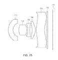
- FIG. 25 is a view of an optical system, according to a seventh embodiment.
- FIG. 26 is graphs having curves illustrating aberration characteristics of the optical system illustrated in FIG. 25 ;
- FIG. 27 is a table illustrating respective characteristics of lenses in the optical system illustrated in FIG. 25 ;
- FIG. 28 is a table illustrating respective aspherical surface coefficients of lenses in the optical system illustrated in FIG. 25 ;
- FIG. 29 is a view of an optical system, according to an eighth embodiment.
- FIG. 30 is graphs having curves illustrating aberration characteristics of the optical system illustrated in FIG. 29 ;
- FIG. 31 is a table illustrating respective characteristics of lenses in the optical system illustrated in FIG. 29 ;
- FIG. 32 is a table illustrating respective aspherical surface coefficients of lenses of the optical system illustrated in FIG. 29 .
- a first lens is a lens closest to an object to be captured
- a fifth lens is a lens closest to an imaging surface of an image sensor
- each lens refers to a surface or an object-side surface thereof closest to an object and a second surface of each lens refers to a surface or an image-side surface thereof closest to an imaging surface of an image sensor.
- a first surface of each lens refers to a surface or an object-side surface thereof closest to an object
- a second surface of each lens refers to a surface or an image-side surface thereof closest to an imaging surface of an image sensor.
- all numerical values of radii of curvature, thicknesses, and other parameters of the lenses are indicated in millimeters (mm). However, a person of ordinary skill in the art will appreciate that other units of measurements may be used.
- a paraxial region refers to a very narrow region in the vicinity of an optical axis. Paraxial region or space region near an axis is where the angle ⁇ between rays and optical axis is so small that sin a and tan a can be replaced with sufficient accuracy by the angle ⁇ .
- the embodiments described of the optical system include five lenses.
- the number of lenses in the optical system may vary, for example, between two to six lenses, while achieving the various results and benefits described hereinbelow.
- the optical system includes a first lens, a second lens, a third lens, a fourth lens, and a fifth lens.
- the optical system is not limited to including only five lenses, but may further include other components, if necessary.
- the optical system may further include a stop controlling an amount of light incident therein.
- the optical system may further include an infrared cut-off filter filtering infrared light.
- the optical system may further include an image sensor converting an image of a subject incident on the image sensor into electrical signals.
- the optical system may further include a gap maintaining member to adjust a gap between lenses.
- lenses included in lens modules are formed of plastic or polycarbonate, a material lighter than glass. In other configurations, some of the lenses included in the modules are formed of plastic or polycarbonate, and other lenses may be formed of glass. According to some configurations, a lens module may include five or more lenses in order to achieve high levels of resolution in images being captured.
- At least one of the first to fifth lenses has an aspherical object-side or image-side surface. Further, each of the first to fifth lenses may have at least one aspherical object-side or image-side surface.
- first and second surfaces of the first to fifth lenses may be aspherical.
- the aspherical surfaces of the first to fifth lenses may be represented by the following Equation 1:
- c curvature (an inverse of a radius of curvature) at an apex of the lens
- K is a conic constant
- Y is a distance from a certain point on the aspherical surface of the lens to an optical axis in a direction perpendicular to the optical axis.
- constants A to F are aspherical surface coefficients.
- Z is a distance between the certain point on the aspherical surface at the distance Y and a tangential plane meeting the apex of the aspherical surface of the lens.
- Each of the first through sixth lenses has a refractive power, either negative or positive.
- the first lens has a positive refractive power
- the second lens has a positive refractive power
- the third lens has a negative refractive power
- the fourth lens has a positive refractive power
- the fifth lens has a negative refractive power
- the sixth lens has a negative refractive power.
- each of the first and sixth lenses may be configured in an opposite refractive power from the configuration described above.
- the first lens has a positive refractive power
- the second lens has a positive refractive power
- the third lens has a negative refractive power
- the fourth lens has a negative refractive power
- the fifth lens has a positive refractive power
- the optical system configured as described above improves optical performance through aberration improvement.
- optical system satisfies Conditional Expression 1. 3.0 ⁇ f 1/ f ⁇ 1.0 [Conditional Expression 1]
- f1 is a focal length of the first lens
- f is an overall focal length of the optical system.
- optical system satisfies Conditional Expression 2. 20 ⁇ v 2 ⁇ v 3 ⁇ 40 [Conditional Expression 2]
- v2 is an Abbe number of the second lens
- v3 is an Abbe number of the third lens.
- optical system satisfies Conditional Expression 3. 20 ⁇ v 1 ⁇ v 3 ⁇ 40 [Conditional Expression 3]
- v1 is an Abbe number of the first lens
- v3 is the Abbe number of the third lens.
- optical system satisfies Conditional Expression 4. 20 ⁇ v 1 ⁇ v 5 ⁇ 40 [Conditional Expression 4]
- v1 is the Abbe number of the first lens
- v5 is an Abbe number of the fifth lens.
- the optical system satisfies Conditional Expression 5. 0 ⁇ f 2/ f ⁇ 1.2 [Conditional Expression 5]
- f2 is a focal length of the second lens
- f is the overall focal length of the optical system.
- optical system may satisfy Conditional Expression 6. 0 ⁇
- f3 is a focal length of the third lens
- f is the overall focal length of the optical system.
- f4 is a focal length of the fourth lens
- f is the overall focal length of the optical system.
- f5 is a focal length of the fifth lens
- f is the overall focal length of the optical system.
- optical system satisfies Conditional Expression 9. OAL/f ⁇ 2.2 [Conditional Expression 9]
- OAL is a distance from an object-side surface of the first lens to an imaging surface of the image sensor
- f is the overall focal length of the optical system.
- the optical system satisfies Conditional Expression 10. 1.0 ⁇
- f1 is the focal length of the first lens
- f2 is the focal length of the second lens
- optical system satisfies Conditional Expression 11. 0.0 ⁇
- f2 is the focal length of the second lens
- f3 is the focal length of the third lens
- BFL is a distance from an image-side surface of the fifth lens to the imaging surface of the image sensor
- f is the overall focal length of the optical system.
- D1 is a distance from an image-side surface of the first lens to an object-side surface of the second lens
- f is the overall focal length of the optical system.
- r3 is a radius of curvature of the object-side surface of the second lens
- f is the overall focal length of the optical system.
- optical system satisfies Conditional Expression 15.
- r8 is a radius of curvature of an image-side surface of the fourth lens
- f is the overall focal length of the optical system.
- FOV is a field of view of the optical system.
- the field of view of the optical system is indicated by degrees.
- FNO is an inverse number of an aperture ratio of the optical system.
- the aperture ratio of the optical system is ‘a diameter of the stop/the overall focal length of the optical system’.
- the first lens has a negative refractive power.
- the first lens has a meniscus shape with the object-side surface being convex.
- a first surface of the first lens is convex in the paraxial region, and a second surface of the first lens is concave in the paraxial region.
- At least one of the first and second surfaces of the first lens is aspherical.
- two surfaces of the first lens are aspherical.
- the second lens has a positive refractive power.
- at least one of the first and the second surfaces of the second lens is convex.
- first and second surfaces of the second lens are convex in the paraxial region.
- At least one of the first and second surfaces of the second lens is aspherical.
- the first and the second surfaces of the second lens are aspherical.
- the third lens has a negative refractive power.
- at least one of the first and second surfaces of the third lens is concave.
- first and second surfaces of the third lens are concave in the paraxial region.
- At least one of the first and second surfaces of the third lens is aspherical.
- the first and the second surfaces of the third lens are aspherical.
- the first surface of the third lens is substantially flat.
- the fourth lens has a positive refractive power.
- the fourth lens has a meniscus shape of which an image-side surface is convex.
- a first surface of the fourth lens is concave in the paraxial region, and a second surface of the fourth lens is convex in the paraxial region.
- end portions of the first surface of the fourth lens are substantially flat.
- At least one of the first and second surfaces of the fourth lens is aspherical.
- the first and the second surfaces of the fourth lens are aspherical.
- the fifth lens has a positive refractive power.
- the fifth lens has a meniscus shape of which an object-side surface is convex.
- a first surface of the fifth lens is convex in the paraxial region, and a second surface of the fifth lens is concave in the paraxial region.
- At least one of the first and second surfaces of the fifth lens is aspherical.
- two surfaces of the fifth lens may be aspherical.
- At least one inflection point is formed on at least one of the first and second surfaces of the fifth lens.
- the first surface of the fifth lens is convex in the paraxial region and becomes concave at an edge thereof.
- the second surface of the fifth lens is concave in the paraxial region and becomes convex at an edge thereof.
- the stop is disposed in front of the object-side surface of the first lens.
- optical system configured, as described above, has a wide field of view, and produces brighter images.
- each of the first through fifth lenses may be separate lenses configured as described above. A distance between lenses may vary. In another embodiment, at least one of the first through fifth lenses may be operatively connected or in contact with another one of the first through fifth lenses.
- two or more of the lenses of the first through fifth lenses may be configured as a group and in operative connection or contact with another lens.
- the first, second, and third lenses may be in contact with each other as a first group lens, while the fourth and fifth lenses are configured separate from each other and from the first group lens.
- the first, second, and third lenses may be in contact with each other as a first group lens, the fourth and the fifth lenses may be in contact with each other as a second group lens.
- FIGS. 1 through 4 An optical system according to a first embodiment will be described with reference to FIGS. 1 through 4 .
- the optical system includes a first lens 110 , a second lens 120 , a third lens 130 , a fourth lens 140 , and a fifth lens 150 .
- the optical system further includes a stop (not shown), an infrared cut-off filter 160 , and an image sensor 170 .
- a focal length (f1) of the first lens 110 is ⁇ 4.463 mm
- a focal length (f2) of the second lens 120 is 1.37668 mm
- a focal length (f3) of the third lens 130 is ⁇ 2.6092 mm
- a focal length (f4) of the fourth lens 140 is 7.52432 mm
- a focal length (f5) of the fifth lens 150 is 75.3369 mm
- an overall focal length (f) of the optical system is 2.3999 mm.
- a distance (OAL) from an object-side surface of the first lens 110 to an imaging surface of the image sensor 170 is 4.970 mm
- a distance (BFL) from an image-side surface of the fifth lens 150 to the imaging surface of the image sensor 170 is 0.931 mm.
- respective characteristics such as radii of curvature, thicknesses, refractive indices, and Abbe numbers, of lenses are illustrated in FIG. 3 .
- the first lens 110 has a negative refractive power, and has a meniscus shape of which the object-side surface is convex.
- a first surface of the first lens 110 is convex, at least, in the paraxial region, and a second surface of the first lens 110 is concave, at least, in the paraxial region.
- the second lens 120 has a positive refractive power, and has a meniscus shape of which two surfaces are convex.
- first and second surfaces of the second lens 120 are convex, at least, in the paraxial region.
- the third lens 130 has a negative refractive power and may have two surfaces which are concave.
- first and second surfaces of the third lens 130 are concave, at least, in the paraxial region.
- the fourth lens 140 has a positive refractive power, and has a meniscus shape of which an image-side surface is convex.
- a first surface of the fourth lens 140 is concave, at least, in the paraxial region, and a second surface of the fourth lens 140 is convex, at least, in the paraxial region.
- the fifth lens 150 has a positive refractive power, and has a meniscus shape of which an object-side surface is convex.
- a first surface of the fifth lens 150 is convex, at least, in the paraxial region, and a second surface of the fifth lens 150 is concave, at least, in the paraxial region.
- the fifth lens 150 has at least one inflection point formed on at least one of the first and second surfaces thereof.
- the respective surfaces of the first to fifth lenses 110 to 150 have aspherical surface coefficients as illustrated in FIG. 4 .
- persons skilled in the art will appreciate that some variation in the aspherical surface coefficients may exist without departing from the results and benefits of the embodiment.
- the stop is positioned in front of the object-side surface of the first lens 110 .
- optical system configured as described above has aberration characteristics as illustrated in FIG. 2 .
- persons skilled in the art will appreciate that some variation in the aberration characteristics may exist without departing from the results and benefits of the first embodiment.
- FIGS. 5 through 8 An optical system, according to a second embodiment, will be described with reference to FIGS. 5 through 8 .
- the optical system includes a first lens 210 , a second lens 220 , a third lens 230 , a fourth lens 240 , and a fifth lens 250 .
- the optical system also includes a stop, an infrared cut-off filter 260 , and an image sensor 270 .
- a focal length (f1) of the first lens 210 is ⁇ 4.524 mm
- a focal length (f2) of the second lens 220 is 1.37888 mm
- a focal length (f3) of the third lens 230 is ⁇ 2.6047 mm
- a focal length (f4) of the fourth lens 240 is 7.57749 mm
- a focal length (f5) of the fifth lens 250 is 1878.49 mm
- an overall focal length (f) of the optical system is 2.4 mm.
- a distance (OAL) from an object-side surface of the first lens 210 to an imaging surface of the image sensor 270 is 4.970 mm
- a distance (BFL) from an image-side surface of the fifth lens 250 to the imaging surface of the image sensor 270 is 0.915 mm.
- the first lens 210 has a negative refractive power, and has a meniscus shape of which an object-side surface is convex.
- a first surface of the first lens 210 is convex, at least, in the paraxial region, and a second surface of the first lens 210 is concave, at least, in the paraxial region.
- the second lens 220 has a positive refractive power, and has a meniscus shape of which two surfaces are convex.
- first and second surfaces of the second lens 220 are convex, at least, in the paraxial region.
- the third lens 230 has a negative refractive power and has two surfaces which are concave.
- first and second surfaces of the third lens 230 are concave, at least, in the paraxial region.
- the fourth lens 240 has a positive refractive power, and has a meniscus shape of which an image-side surface is convex.
- a first surface of the fourth lens 240 is concave, at least, in the paraxial region, and a second surface of the fourth lens 240 is convex, at least, in the paraxial region.
- the fifth lens 250 has a positive refractive power, and has a meniscus shape of which an object-side surface is convex.
- a first surface of the fifth lens 250 is convex, at least, in the paraxial region, and a second surface of the fifth lens 250 is concave, at least, in the paraxial region.
- the fifth lens 250 has at least one inflection point formed on at least one of the first and second surfaces thereof.
- the respective surfaces of the first to fifth lenses 210 to 250 have aspherical surface coefficients as illustrated in FIG. 8 .
- aspherical surface coefficients may exist without departing from the results and benefits of the embodiment.
- the stop is disposed in front of the object-side surface of the first lens 210 .
- optical system configured as described above may have aberration characteristics as illustrated in FIG. 6 .
- persons skilled in the art will appreciate that some variation in the aberration characteristics may exist without departing from the results and benefits of the embodiment.
- the optical system may include a first lens 310 , a second lens 320 , a third lens 330 , a fourth lens 340 , and a fifth lens 350 .
- the optical system also includes a stop, an infrared cut-off filter 360 , and an image sensor 370 .
- a focal length (f1) of the first lens 310 is ⁇ 4.3907 mm
- a focal length (f2) of the second lens 320 is 1.35421 mm
- a focal length (f3) of the third lens 330 is ⁇ 2.5297 mm
- a focal length (f4) of the fourth lens 340 is 7.20756 mm
- a focal length (f5) of the fifth lens 350 is 5493.18 mm
- an overall focal length (f) of the optical system is 2.3685 mm.
- a distance (OAL) from an object-side surface of the first lens 310 to an imaging surface of the image sensor 370 is 4.925 mm
- a distance (BFL) from an image-side surface of the fifth lens 350 to the imaging surface of the image sensor 370 is 0.915 mm.
- respective characteristics such as radii of curvature, thicknesses, refractive indices, and Abbe numbers, of lenses are illustrated in FIG. 11 .
- the first lens 310 has a negative refractive power, and has a meniscus shape of which an object-side surface is convex.
- a first surface of the first lens 310 is convex, at least, in the paraxial region, and a second surface of the first lens 310 is concave, at least, in the paraxial region.
- the second lens 320 has a positive refractive power, and has a meniscus shape of which two surfaces are convex.
- first and second surfaces of the second lens 320 are convex, at least, in the paraxial region.
- the third lens 330 has a negative refractive power and has two surfaces which are concave.
- first and second surfaces of the third lens 330 are concave, at least, in the paraxial region.
- the fourth lens 340 has a positive refractive power, and has a meniscus shape of which an image-side surface is convex.
- a first surface of the fourth lens 340 is concave, at least, in the paraxial region, and a second surface of the fourth lens 340 is convex, at least, in the paraxial region.
- the fifth lens 350 has a positive refractive power, and has a meniscus shape of which an object-side surface is convex.
- a first surface of the fifth lens 350 is convex, at least, in the paraxial region, and a second surface of the fifth lens 350 is concave, at least, in the paraxial region.
- the fifth lens 350 has at least one inflection point formed on at least one of the first and second surfaces thereof.
- the respective surfaces of the first to fifth lenses 310 to 350 have aspherical surface coefficients as illustrated in FIG. 12 .
- aspherical surface coefficients may exist without departing from the results and benefits of the embodiment.
- the stop is disposed in front of the object-side surface of the first lens 310 .
- optical system configured as described above has aberration characteristics as illustrated in FIG. 10 .
- persons skilled in the art will appreciate that some variation in the aberration characteristics may exist without departing from the results and benefits of the embodiment.
- the optical system includes a first lens 410 , a second lens 420 , a third lens 430 , a fourth lens 440 , and a fifth lens 450 .
- the optical system also includes a stop, an infrared cut-off filter 460 , and an image sensor 470 .
- a focal length (f1) of the first lens 410 is ⁇ 4.4528 mm
- a focal length (f2) of the second lens 420 is 1.37069 mm
- a focal length (f3) of the third lens 430 is ⁇ 2.5788 mm
- a focal length (f4) of the fourth lens 440 is 7.28033 mm
- a focal length (f5) of the fifth lens 450 is 509.557 mm
- an overall focal length (f) of the optical system is 2.4 mm.
- a distance (OAL) from an object-side surface of the first lens 410 to an imaging surface of the image sensor 470 is 4.971 mm
- a distance (BFL) from an image-side surface of the fifth lens 450 to the imaging surface of the image sensor 470 is 0.924 mm.
- respective characteristics such as radii of curvature, thicknesses of lenses or distances between the lenses, refractive indices, and Abbe numbers, of lenses are illustrated in FIG. 15 .
- the first lens 410 has a negative refractive power, and has a meniscus shape of which an object-side surface is convex.
- a first surface of the first lens 410 is convex, at least, in the paraxial region, and a second surface of the first lens 410 is concave, at least, in the paraxial region.
- the second lens 420 has a positive refractive power, and has a meniscus shape of which two surfaces are convex.
- first and second surfaces of the second lens 420 are convex, at least, in the paraxial region.
- the third lens 430 has a negative refractive power and has two surfaces that are concave.
- first and second surfaces of the third lens 430 are concave, at least, in the paraxial region.
- the fourth lens 440 has a positive refractive power, and has a meniscus shape of which an image-side surface is convex.
- a first surface of the fourth lens 440 is concave, at least, in the paraxial region, and a second surface of the fourth lens 440 is convex, at least, in the paraxial region.
- the fifth lens 450 has a positive refractive power, and has a meniscus shape of which an object-side surface is convex.
- a first surface of the fifth lens 450 is convex, at least, in the paraxial region, and a second surface of the fifth lens 450 is concave, at least, in the paraxial region.
- the fifth lens 450 has at least one inflection point formed on at least one of the first and second surfaces thereof.
- the respective surfaces of the first to fifth lenses 410 to 450 have aspherical surface coefficients as illustrated in FIG. 16 .
- aspherical surface coefficients may exist without departing from the results and benefits of the embodiment.
- the stop is disposed in front of the object-side surface of the first lens 410 .
- optical system configured as described above has aberration characteristics as illustrated in FIG. 14 .
- persons skilled in the art will appreciate that some variation in the aberration characteristics may exist without departing from the results and benefits of the embodiment.
- the optical system includes a first lens 510 , a second lens 520 , a third lens 530 , a fourth lens 540 , and a fifth lens 550 .
- the optical system also includes a stop, an infrared cut-off filter 560 , and an image sensor 570 .
- a focal length (f1) of the first lens 510 is ⁇ 4.5045 mm
- a focal length (f2) of the second lens 520 is 1.36938 mm
- a focal length (f3) of the third lens 530 is ⁇ 2.5479 mm
- a focal length (f4) of the fourth lens 540 is 7.29404 mm
- a focal length (f5) of the fifth lens 550 is 115.841 mm
- an overall focal length (f) of the optical system is 2.4 mm.
- a distance (OAL) from an object-side surface of the first lens 510 to an imaging surface of the image sensor 570 is 4.971 mm
- a distance (BFL) from an image-side surface of the fifth lens 550 to the imaging surface of the image sensor 570 is 0.925 mm.
- respective characteristics such as radii of curvature, thicknesses of lenses or distances between the lenses, refractive indices, and Abbe numbers, of lenses are illustrated in FIG. 19 .
- the first lens 510 has a negative refractive power, and has a meniscus shape of which an object-side surface is convex.
- a first surface of the first lens 510 is convex, at least, in the paraxial region, and a second surface of the first lens 510 is concave, at least, in the paraxial region.
- the second lens 520 has a positive refractive power, and has a meniscus shape of which two surfaces are convex.
- first and second surfaces of the second lens 520 are convex, at least, in the paraxial region.
- the third lens 530 has a negative refractive power and has two surfaces which are concave.
- first and second surfaces of the third lens 530 are concave, at least, in the paraxial region.
- the fourth lens 540 has a positive refractive power, and has a meniscus shape of which an image-side surface is convex.
- a first surface of the fourth lens 540 is concave, at least, in the paraxial region, and a second surface of the fourth lens 540 is convex, at least, in the paraxial region.
- the fifth lens 550 has a positive refractive power, and has a meniscus shape of which an object-side surface is convex.
- a first surface of the fifth lens 550 is convex, at least, in the paraxial region, and a second surface of the fifth lens 550 is concave, at least, in the paraxial region.
- the fifth lens 550 has at least one inflection point formed on at least one of the first and second surfaces thereof.
- the respective surfaces of the first to fifth lenses 510 to 550 have aspherical surface coefficients as illustrated in FIG. 20 .
- aspherical surface coefficients may exist without departing from the results and benefits of the embodiment.
- the stop is disposed in front of the object-side surface of the first lens 510 .
- optical system configured as described above has aberration characteristics as illustrated in FIG. 18 .
- persons skilled in the art will appreciate that some variation in the aberration characteristics may exist without departing from the results and benefits of the embodiment.
- the optical system includes a first lens 610 , a second lens 620 , a third lens 630 , a fourth lens 640 , and a fifth lens 650 .
- the optical system also includes a stop, an infrared cut-off filter 660 , and an image sensor 670 .
- a focal length (f1) of the first lens 610 is ⁇ 4.539 mm
- a focal length (f2) of the second lens 620 is 1.36576 mm
- a focal length (f3) of the third lens 630 is ⁇ 2.5133 mm
- a focal length (f4) of the fourth lens 640 is 7.18089 mm
- a focal length (f5) of the fifth lens 650 is 70.5881 mm
- an overall focal length (f) of the optical system is 2.4 mm.
- a distance (OAL) from an object-side surface of the first lens 610 to an imaging surface of the image sensor 670 is 4.971 mm
- a distance (BFL) from an image-side surface of the fifth lens 650 to the imaging surface of the image sensor 670 is 0.936 mm.
- respective characteristics such as radii of curvature, thicknesses, refractive indices, and Abbe numbers, of lenses are illustrated in FIG. 23 .
- the first lens 610 has a negative refractive power, and has a meniscus shape of which an object-side surface is convex.
- a first surface of the first lens 610 is convex, at least, in the paraxial region, and a second surface of the first lens 610 is concave, at least, in the paraxial region.
- the second lens 620 has a positive refractive power, and has a meniscus shape of which two surfaces are convex.
- first and second surfaces of the second lens 620 are convex, at least, in the paraxial region.
- the third lens 630 has a negative refractive power and has two surfaces that are concave.
- first and second surfaces of the third lens 630 are concave, at least, in the paraxial region.
- the fourth lens 640 has a positive refractive power, and has a meniscus shape of which an image-side surface is convex.
- a first surface of the fourth lens 640 is concave, at least, in the paraxial region, and a second surface of the fourth lens 640 is convex, at least, in the paraxial region.
- the fifth lens 650 has a positive refractive power, and has a meniscus shape of which an object-side surface is convex.
- a first surface of the fifth lens 650 is convex, at least, in the paraxial region, and a second surface of the fifth lens 650 is concave, at least, in the paraxial region.
- the fifth lens 650 has at least one inflection point formed on at least one of the first and second surfaces thereof.
- the respective surfaces of the first to fifth lenses 610 to 650 have aspherical surface coefficients as illustrated in FIG. 24 .
- aspherical surface coefficients may exist without departing from the results and benefits of the embodiment.
- the stop is disposed in front of the object-side surface of the first lens 610 .
- optical system configured as described above has aberration characteristics as illustrated in FIG. 22 .
- persons skilled in the art will appreciate that some variation in the aberration characteristics may exist without departing from the results and benefits of the embodiment.
- the optical system includes a first lens 710 , a second lens 720 , a third lens 730 , a fourth lens 740 , and a fifth lens 750 .
- the optical system also includes a stop, an infrared cut-off filter 760 , and an image sensor 770 .
- a focal length (f1) of the first lens 710 is ⁇ 4.6117 mm
- a focal length (f2) of the second lens 720 is 1.3626 mm
- a focal length (f3) of the third lens 730 is ⁇ 2.4673 mm
- a focal length (f4) of the fourth lens 740 is 6.6595 mm
- a focal length (f5) of the fifth lens 750 is 51.8561 mm
- an overall focal length (f) of the optical system is 2.4 mm.
- a distance (OAL) from an object-side surface of the first lens 710 to an imaging surface of the image sensor 770 is 4.971 mm
- a distance (BFL) from an image-side surface of the fifth lens 750 to the imaging surface of the image sensor 770 is 0.916 mm.
- respective characteristics such as radii of curvature, thicknesses, refractive indices, and Abbe numbers, of lenses are illustrated in FIG. 27 .
- the first lens 710 has a negative refractive power, and has a meniscus shape of which an object-side surface is convex.
- a first surface of the first lens 710 is convex, at least, in the paraxial region, and a second surface of the first lens 710 is concave, at least, in the paraxial region.
- the second lens 720 has a positive refractive power, and has a meniscus shape of which two surfaces are convex.
- first and second surfaces of the second lens 720 are convex, at least, in the paraxial region.
- the third lens 730 has a negative refractive power and has two surfaces that are concave.
- first and second surfaces of the third lens 730 are concave, at least, in the paraxial region.
- the fourth lens 740 has a positive refractive power, and has a meniscus shape of which an image-side surface is convex.
- a first surface of the fourth lens 740 is concave, at least, in the paraxial region, and a second surface of the fourth lens 740 is convex, at least, in the paraxial region.
- the fifth lens 750 has a positive refractive power, and has a meniscus shape of which an object-side surface is convex.
- a first surface of the fifth lens 750 is convex, at least, in the paraxial region, and a second surface of the fifth lens 750 is concave, at least, in the paraxial region.
- the fifth lens 750 has at least one inflection point formed on at least one of the first and second surfaces thereof.
- the respective surfaces of the first to fifth lenses 710 to 750 have aspherical surface coefficients as illustrated in FIG. 28 .
- aspherical surface coefficients may exist without departing from the results and benefits of the embodiment.
- the stop is disposed in front of the object-side surface of the first lens 710 .
- optical system configured as described above has aberration characteristics as illustrated in FIG. 26 .
- persons skilled in the art will appreciate that some variation in the aberration characteristics may exist without departing from the results and benefits of the embodiment.
- the optical system includes a first lens 810 , a second lens 820 , a third lens 830 , a fourth lens 840 , and a fifth lens 850 .
- the optical system also includes a stop, an infrared cut-off filter 860 , and an image sensor 870 .
- a focal length (f1) of the first lens 810 is ⁇ 4.5835 mm
- a focal length (f2) of the second lens 820 is 1.36287 mm
- a focal length (f3) of the third lens 830 is ⁇ 2.465 mm
- a focal length (f4) of the fourth lens 840 is 6.12052 mm
- a focal length (f5) of the fifth lens 850 is 70.0162 mm
- an overall focal length (f) of the optical system is 2.4 mm.
- a distance (OAL) from an object-side surface of the first lens 810 to an imaging surface of the image sensor 870 is 4.971 mm
- a distance (BFL) from an image-side surface of the fifth lens 850 to the imaging surface of the image sensor 870 is 0.962 mm.
- the first lens 810 has a negative refractive power, and has a meniscus shape of which an object-side surface is convex.
- a first surface of the first lens 810 is convex, at least, in the paraxial region, and a second surface of the first lens 810 is concave, at least, in the paraxial region.
- the second lens 820 has a positive refractive power, and has a meniscus shape of which two surfaces are convex.
- first and second surfaces of the second lens 820 are convex, at least, in the paraxial region.
- the third lens 830 has a negative refractive power and has two surfaces that are concave.
- first and second surfaces of the third lens 830 are concave, at least, in the paraxial region.
- the fourth lens 840 has a positive refractive power, and has a meniscus shape of which an image-side surface is convex.
- a first surface of the fourth lens 840 is concave, at least, in the paraxial region, and a second surface of the fourth lens 840 is convex, at least, in the paraxial region.
- the fifth lens 850 has a positive refractive power, and has a meniscus shape of which an object-side surface is convex.
- a first surface of the fifth lens 850 is convex, at least, in the paraxial region, and a second surface of the fifth lens 850 is concave, at least, in the paraxial region.
- the fifth lens 850 has at least one inflection point formed on at least one of the first and second surfaces thereof.
- the respective surfaces of the first to fifth lenses 810 to 850 have aspherical surface coefficients as illustrated in FIG. 32 .
- aspherical surface coefficients may exist without departing from the results and benefits of the embodiment.
- the stop is disposed in front of the object-side surface of the first lens 810 .
- optical system configured as described above has aberration characteristics as illustrated in FIG. 30 .
- persons skilled in the art will appreciate that some variation in the aberration characteristics may exist without departing from the results and benefits of the embodiment.
- the optical systems according to the first to eighth embodiments, satisfy the above-mentioned Conditional Expressions 1 through 17, such that optical performances of the lenses are improved, a wide field of view and a brighter image are realized.
- Example 2 Example 3
- Example 4 Example 5
- Example 6 Example 7
- Example 8 ⁇ 3.0 ⁇ f1/f ⁇ ⁇ 1.0 ⁇ 1.86 ⁇ 1.89 ⁇ 1.85 ⁇ 1.86 ⁇ 1.88 ⁇ 1.89 ⁇ 1.92 ⁇ 1.91 20 ⁇ v2 ⁇ v3 ⁇ 40 32.60 32.60 32.60 32.60 32.60 32.60 32.60 20 ⁇ v1 ⁇ v3 ⁇ 40 32.60 32.60 32.60 32.60 32.60 32.60 32.60 32.60 20 ⁇ v1 ⁇ v5 ⁇ 40 32.60 32.60 32.60 32.60 32.60 32.60 32.60 32.60 0 ⁇ f2/f ⁇ 1.2 0.57 0.57 0.57 0.57 0.57 0.57 0.57 0.57 0 ⁇
- an aberration improvement effect is increased, while a wide field of view and high levels of resolution are produced.
- the fifth lens to be in contact to the infrared cut-off filter may be placed at a distance from the infrared cut-off filter.
- the infrared cut-off filter may be shaped to mirror the image-side surface or the second surface of the fifth lens, thereby forming an integral part of the fifth lens.
- each of the first to fifth lenses may be separate lenses configured as described above. A distance between lenses may vary. In another embodiment, at least one of the first to fifth lenses may be operatively connected or in contact with another one of the first to fifth lenses.
- two or more of the lenses of the first to fifth lenses may be configured as a group and in operative connection or contact with another lens.
- the first, second, and third lenses may be in contact with each other as a first group lens, while the fourth and fifth lenses are configured separate from each other and from the first group lens.
- the first, second, and third lenses may be in contact with each other as a first group lens, and the fourth and the fifth lenses may be in contact with each other as a second group lens.
Landscapes
- Physics & Mathematics (AREA)
- General Physics & Mathematics (AREA)
- Optics & Photonics (AREA)
- Lenses (AREA)
Abstract
Description
3.0<f1/f<−1.0 [Conditional Expression 1]
20<v2−v3<40 [Conditional Expression 2]
20<v1−v3<40 [Conditional Expression 3]
20<v1−v5<40 [Conditional Expression 4]
0<f2/f<1.2 [Conditional Expression 5]
0<|f3/f|<2.0 [Conditional Expression 6]
f4/f>2.0 [Conditional Expression 7]
f5/f>0 [Conditional Expression 8]
OAL/f<2.2 [Conditional Expression 9]
1.0<|f1/f2|<5.0 [Conditional Expression 10]
0.0<|f2/f3|<1.4 [Conditional Expression 11]
BFL/f<0.55 [Conditional Expression 12]
D1/f<0.5 [Conditional Expression 13]
r3/f>0.4 [Conditional Expression 14]
|r8/f|>0.3 [Conditional Expression 15]
FOV>80 [Conditional Expression 16]
FNO<2.2 [Conditional Expression 17]
| TABLE 1 | |||
| f | 2.3999 | ||
| f1 | −4.463 | ||
| f2 | 1.376677 | ||
| f3 | −2.6092 | ||
| f4 | 7.524322 | ||
| f5 | 75.33687 | ||
| v1 | 56.1 | ||
| v2 | 56.1 | ||
| v3 | 23.5 | ||
| v4 | 56.1 | ||
| v5 | 23.5 | ||
| OAL | 4.970 | ||
| BFL | 0.931 | ||
| TABLE 2 | |||
| f | 2.4 | ||
| f1 | −4.524 | ||
| f2 | 1.378883 | ||
| f3 | −2.6047 | ||
| f4 | 7.577489 | ||
| f5 | 1878.492 | ||
| v1 | 56.1 | ||
| v2 | 56.1 | ||
| v3 | 23.5 | ||
| v4 | 56.1 | ||
| v5 | 23.5 | ||
| OAL | 4.970 | ||
| BFL | 0.915 | ||
| TABLE 3 | |||
| f | 2.3685 | ||
| f1 | −4.3907 | ||
| f2 | 1.354205 | ||
| f3 | −2.5297 | ||
| f4 | 7.207562 | ||
| f5 | 5493.179 | ||
| v1 | 56.1 | ||
| v2 | 56.1 | ||
| v3 | 23.5 | ||
| v4 | 56.1 | ||
| v5 | 23.5 | ||
| OAL | 4.925 | ||
| BFL | 0.915 | ||
| TABLE 4 | |||
| f | 2.4 | ||
| f1 | −4.4528 | ||
| f2 | 1.370692 | ||
| f3 | −2.5788 | ||
| f4 | 7.28033 | ||
| f5 | 509.5573 | ||
| v1 | 56.1 | ||
| v2 | 56.1 | ||
| v3 | 23.5 | ||
| v4 | 56.1 | ||
| v5 | 23.5 | ||
| OAL | 4.971 | ||
| BFL | 0.924 | ||
| TABLE 5 | |||
| f | 2.4 | ||
| f1 | −4.5045 | ||
| f2 | 1.369378 | ||
| f3 | −2.5479 | ||
| f4 | 7.294039 | ||
| f5 | 115.8407 | ||
| v1 | 56.1 | ||
| v2 | 56.1 | ||
| v3 | 23.5 | ||
| v4 | 56.1 | ||
| v5 | 23.5 | ||
| OAL | 4.971 | ||
| BFL | 0.925 | ||
| TABLE 6 | |||
| f | 2.4 | ||
| f1 | −4.539 | ||
| f2 | 1.36576 | ||
| f3 | −2.5133 | ||
| f4 | 7.180889 | ||
| f5 | 70.58813 | ||
| v1 | 56.1 | ||
| v2 | 56.1 | ||
| v3 | 23.5 | ||
| v4 | 56.1 | ||
| v5 | 23.5 | ||
| OAL | 4.971 | ||
| BFL | 0.936 | ||
| TABLE 7 | |||
| f | 2.4 | ||
| f1 | −4.6117 | ||
| f2 | 1.362602 | ||
| f3 | −2.4673 | ||
| f4 | 6.659498 | ||
| f5 | 51.85608 | ||
| v1 | 56.1 | ||
| v2 | 56.1 | ||
| v3 | 23.5 | ||
| v4 | 56.1 | ||
| v5 | 23.5 | ||
| OAL | 4.971 | ||
| BFL | 0.916 | ||
| TABLE 8 | |||
| f | 2.4 | ||
| f1 | −4.5835 | ||
| f2 | 1.362868 | ||
| f3 | −2.465 | ||
| f4 | 6.120523 | ||
| f5 | 70.0162 | ||
| v1 | 56.1 | ||
| v2 | 56.1 | ||
| v3 | 23.5 | ||
| v4 | 56.1 | ||
| v5 | 23.5 | ||
| OAL | 4.971 | ||
| BFL | 0.962 | ||
| TABLE 9 | ||||||||
| Conditional Expression | Example 1 | Example 2 | Example 3 | Example 4 | Example 5 | Example 6 | Example 7 | Example 8 |
| −3.0 < f1/f < −1.0 | −1.86 | −1.89 | −1.85 | −1.86 | −1.88 | −1.89 | −1.92 | −1.91 |
| 20 < v2 − v3 < 40 | 32.60 | 32.60 | 32.60 | 32.60 | 32.60 | 32.60 | 32.60 | 32.60 |
| 20 < v1 − v3 < 40 | 32.60 | 32.60 | 32.60 | 32.60 | 32.60 | 32.60 | 32.60 | 32.60 |
| 20 < v1 − v5 < 40 | 32.60 | 32.60 | 32.60 | 32.60 | 32.60 | 32.60 | 32.60 | 32.60 |
| 0 < f2/f < 1.2 | 0.57 | 0.57 | 0.57 | 0.57 | 0.57 | 0.57 | 0.57 | 0.57 |
| 0 < |f3/f| < 2.0 | −1.09 | −1.09 | −1.07 | −1.07 | −1.06 | −1.05 | −1.03 | −1.03 |
| f4/f > 2.0 | 3.14 | 3.16 | 3.04 | 3.03 | 3.04 | 2.99 | 2.77 | 2.55 |
| f5/f > 0.0 | 31.39 | 782.70 | 2319.26 | 212.32 | 48.27 | 29.41 | 21.61 | 29.17 |
| OAL/f < 2.2 | 2.07 | 2.07 | 2.08 | 2.07 | 2.07 | 2.07 | 2.07 | 2.07 |
| 1.0 < |f1/f2| < 5.0 | −3.24 | −3.28 | −3.24 | −3.25 | −3.29 | −3.32 | −3.38 | −3.36 |
| 0.0 < |f2/f3| < 1.4 | −0.53 | −0.53 | −0.54 | −0.53 | −0.54 | −0.54 | −0.55 | −0.55 |
| BFL/f < 0.55 | 0.39 | 0.38 | 0.39 | 0.38 | 0.39 | 0.39 | 0.38 | 0.40 |
| Df/f < 0.5 | 0.26 | 0.27 | 0.27 | 0.27 | 0.27 | 0.27 | 0.28 | 0.28 |
| r3/f > 0.4 | 0.53 | 0.53 | 0.53 | 0.53 | 0.53 | 0.53 | 0.53 | 0.53 |
| |r8/f| > 0.3 | −0.49 | −0.48 | −0.48 | −0.47 | −0.48 | −0.47 | −0.47 | −0.45 |
| FOV | 84.9 | 84.9 | 85.6 | 84.9 | 84.9 | 84.9 | 84.9 | 84.9 |
| FNO | 2.14 | 2.16 | 2.17 | 2.17 | 2.17 | 2.16 | 2.15 | 2.16 |
Claims (17)
Applications Claiming Priority (2)
| Application Number | Priority Date | Filing Date | Title |
|---|---|---|---|
| KR10-2014-0168479 | 2014-11-28 | ||
| KR1020140168479A KR101701008B1 (en) | 2014-11-28 | 2014-11-28 | Optical system |
Publications (2)
| Publication Number | Publication Date |
|---|---|
| US20160154212A1 US20160154212A1 (en) | 2016-06-02 |
| US10067317B2 true US10067317B2 (en) | 2018-09-04 |
Family
ID=56079102
Family Applications (1)
| Application Number | Title | Priority Date | Filing Date |
|---|---|---|---|
| US14/938,252 Active 2036-07-31 US10067317B2 (en) | 2014-11-28 | 2015-11-11 | Optical system |
Country Status (3)
| Country | Link |
|---|---|
| US (1) | US10067317B2 (en) |
| KR (1) | KR101701008B1 (en) |
| CN (1) | CN105652411B (en) |
Families Citing this family (7)
| Publication number | Priority date | Publication date | Assignee | Title |
|---|---|---|---|---|
| TWI601994B (en) | 2015-12-15 | 2017-10-11 | 大立光電股份有限公司 | Optical lens set, image capturing device and electronic device |
| KR102789031B1 (en) * | 2016-12-27 | 2025-04-01 | 삼성전기주식회사 | Optical system |
| KR101872857B1 (en) * | 2017-03-14 | 2018-06-29 | 주식회사 엔투에이 | Subminiature wide angle image pickup lens system |
| TWI629501B (en) * | 2017-04-28 | 2018-07-11 | 聲遠精密光學股份有限公司 | Wide angle imaging lens assembly |
| TWI766956B (en) * | 2018-03-06 | 2022-06-11 | 大陸商信泰光學(深圳)有限公司 | Lens assembly |
| CN110231706B (en) * | 2018-03-06 | 2021-03-05 | 信泰光学(深圳)有限公司 | Imaging lens |
| CN110727084A (en) * | 2019-10-30 | 2020-01-24 | 玉晶光电(厦门)有限公司 | Optical imaging lens |
Citations (15)
| Publication number | Priority date | Publication date | Assignee | Title |
|---|---|---|---|---|
| JPH11223762A (en) | 1998-02-09 | 1999-08-17 | Canon Inc | Objective lens |
| JP2000066095A (en) | 1999-09-10 | 2000-03-03 | Asahi Optical Co Ltd | Imaging lens |
| US20040008426A1 (en) | 2001-12-14 | 2004-01-15 | Nidec Copal Corporation | Wide-angle lens |
| TW201235694A (en) | 2012-05-18 | 2012-09-01 | Largan Precision Co Ltd | Image lens system |
| TW201245758A (en) | 2012-07-27 | 2012-11-16 | Largan Precision Co Ltd | Optical image capturing lens system |
| CN103076665A (en) | 2011-10-26 | 2013-05-01 | 鸿富锦精密工业(深圳)有限公司 | Lens for capturing image |
| KR20130055137A (en) | 2011-11-18 | 2013-05-28 | 엘지이노텍 주식회사 | Imaging lens |
| TW201403121A (en) | 2013-10-14 | 2014-01-16 | Largan Precision Co Ltd | Optical image capturing system, image capturing device and mobile terminal |
| CN103901586A (en) | 2014-04-13 | 2014-07-02 | 浙江舜宇光学有限公司 | 3D interaction-type projection lens |
| US20140211328A1 (en) | 2013-01-25 | 2014-07-31 | Kantatsu Co., Ltd. | Imaging lens |
| WO2014132317A1 (en) | 2013-02-28 | 2014-09-04 | 富士フイルム株式会社 | Imaging lens and imaging device |
| US9097877B2 (en) * | 2013-07-23 | 2015-08-04 | Largan Precision Co., Ltd. | Image lens assembly and image capturing device |
| US9201216B2 (en) * | 2014-01-24 | 2015-12-01 | Largan Precision Co., Ltd. | Image capturing lens assembly, image capturing device and mobile terminal |
| US9411134B1 (en) * | 2015-06-10 | 2016-08-09 | Largan Precision Co., Ltd. | Optical imaging lens assembly, image capturing unit and electronic device |
| US9435985B2 (en) * | 2015-01-16 | 2016-09-06 | Largan Precision Co., Ltd. | Optical imaging system, image capturing unit and electronic device |
Family Cites Families (1)
| Publication number | Priority date | Publication date | Assignee | Title |
|---|---|---|---|---|
| JP2003149546A (en) * | 2001-11-15 | 2003-05-21 | Casio Comput Co Ltd | Shooting lens |
-
2014
- 2014-11-28 KR KR1020140168479A patent/KR101701008B1/en active Active
-
2015
- 2015-11-11 US US14/938,252 patent/US10067317B2/en active Active
- 2015-11-27 CN CN201510847683.9A patent/CN105652411B/en active Active
Patent Citations (22)
| Publication number | Priority date | Publication date | Assignee | Title |
|---|---|---|---|---|
| JPH11223762A (en) | 1998-02-09 | 1999-08-17 | Canon Inc | Objective lens |
| JP2000066095A (en) | 1999-09-10 | 2000-03-03 | Asahi Optical Co Ltd | Imaging lens |
| US20040008426A1 (en) | 2001-12-14 | 2004-01-15 | Nidec Copal Corporation | Wide-angle lens |
| JP2013092775A (en) | 2011-10-26 | 2013-05-16 | Kofukin Seimitsu Kogyo (Shenzhen) Yugenkoshi | Lens system |
| CN103076665A (en) | 2011-10-26 | 2013-05-01 | 鸿富锦精密工业(深圳)有限公司 | Lens for capturing image |
| US20130107375A1 (en) | 2011-10-26 | 2013-05-02 | Hon Hai Precision Industry Co., Ltd. | Image lens with low chromatic aberration and high resolution |
| KR20130055137A (en) | 2011-11-18 | 2013-05-28 | 엘지이노텍 주식회사 | Imaging lens |
| TW201235694A (en) | 2012-05-18 | 2012-09-01 | Largan Precision Co Ltd | Image lens system |
| US20130308206A1 (en) | 2012-05-18 | 2013-11-21 | Largan Precision Co., Ltd. | Image lens system |
| TW201245758A (en) | 2012-07-27 | 2012-11-16 | Largan Precision Co Ltd | Optical image capturing lens system |
| US20140029116A1 (en) | 2012-07-27 | 2014-01-30 | Largan Precision Co., Ltd. | Optical image capturing lens system |
| US8649113B1 (en) * | 2012-07-27 | 2014-02-11 | Largan Precision Co., Ltd. | Optical image capturing lens system |
| US20140211328A1 (en) | 2013-01-25 | 2014-07-31 | Kantatsu Co., Ltd. | Imaging lens |
| WO2014132317A1 (en) | 2013-02-28 | 2014-09-04 | 富士フイルム株式会社 | Imaging lens and imaging device |
| US20150346458A1 (en) | 2013-02-28 | 2015-12-03 | Fujifilm Corporation | Imaging lens and imaging apparatus |
| US9097877B2 (en) * | 2013-07-23 | 2015-08-04 | Largan Precision Co., Ltd. | Image lens assembly and image capturing device |
| TW201403121A (en) | 2013-10-14 | 2014-01-16 | Largan Precision Co Ltd | Optical image capturing system, image capturing device and mobile terminal |
| US20150103225A1 (en) | 2013-10-14 | 2015-04-16 | Largan Precision Co., Ltd. | Optical image capturing system, image capturing device and mobile terminal |
| US9201216B2 (en) * | 2014-01-24 | 2015-12-01 | Largan Precision Co., Ltd. | Image capturing lens assembly, image capturing device and mobile terminal |
| CN103901586A (en) | 2014-04-13 | 2014-07-02 | 浙江舜宇光学有限公司 | 3D interaction-type projection lens |
| US9435985B2 (en) * | 2015-01-16 | 2016-09-06 | Largan Precision Co., Ltd. | Optical imaging system, image capturing unit and electronic device |
| US9411134B1 (en) * | 2015-06-10 | 2016-08-09 | Largan Precision Co., Ltd. | Optical imaging lens assembly, image capturing unit and electronic device |
Non-Patent Citations (3)
| Title |
|---|
| Chinese Office Action dated Jul. 28, 2017 in corresponding Chinese Patent Application No. 201510847683.9. (8 pages in English and 7 pages in Chinese). |
| Chinese Office Action dated March 19, 2018 in counterpart Chinese Patent Application No. 201510847683.9 (20 pages, in Chinese with English translation). |
| Korean Office Action dated Aug. 19, 2016 in counterpart Korean Application No. 10-2014-0168479. (18 pages with English Translation). |
Also Published As
| Publication number | Publication date |
|---|---|
| US20160154212A1 (en) | 2016-06-02 |
| KR101701008B1 (en) | 2017-01-31 |
| KR20160064642A (en) | 2016-06-08 |
| CN105652411A (en) | 2016-06-08 |
| CN105652411B (en) | 2019-01-01 |
Similar Documents
| Publication | Publication Date | Title |
|---|---|---|
| US20240151946A1 (en) | Optical system | |
| US20250284040A1 (en) | Optical system | |
| US12111445B2 (en) | Optical imaging system | |
| US11982793B2 (en) | Lens module | |
| US12228794B2 (en) | Optical system | |
| US11906705B2 (en) | Optical system | |
| US11656434B2 (en) | Optical imaging system | |
| US9791671B2 (en) | Optical system | |
| US11333857B2 (en) | Optical system | |
| US9759893B2 (en) | Optical device and mobile device including a plurality of optical devices having different fields of view | |
| US10852509B2 (en) | Optical system | |
| US9645355B2 (en) | Lens module | |
| US10067317B2 (en) | Optical system | |
| US10061103B2 (en) | Lens module | |
| US10067318B2 (en) | Optical imaging system | |
| US9678308B2 (en) | Optical system |
Legal Events
| Date | Code | Title | Description |
|---|---|---|---|
| AS | Assignment |
Owner name: SAMSUNG ELECTRO-MECHANICS CO., LTD., KOREA, REPUBL Free format text: ASSIGNMENT OF ASSIGNORS INTEREST;ASSIGNORS:PARK, IL YONG;JO, YONG JOO;REEL/FRAME:037014/0435 Effective date: 20151013 |
|
| STCF | Information on status: patent grant |
Free format text: PATENTED CASE |
|
| MAFP | Maintenance fee payment |
Free format text: PAYMENT OF MAINTENANCE FEE, 4TH YEAR, LARGE ENTITY (ORIGINAL EVENT CODE: M1551); ENTITY STATUS OF PATENT OWNER: LARGE ENTITY Year of fee payment: 4 |
|
| MAFP | Maintenance fee payment |
Free format text: PAYMENT OF MAINTENANCE FEE, 8TH YEAR, LARGE ENTITY (ORIGINAL EVENT CODE: M1552); ENTITY STATUS OF PATENT OWNER: LARGE ENTITY Year of fee payment: 8 |