US10066808B2 - Optical system for luminaries and LED lighting - Google Patents

Optical system for luminaries and LED lighting Download PDF

Info

Publication number
US10066808B2
US10066808B2 US15/330,418 US201515330418A US10066808B2 US 10066808 B2 US10066808 B2 US 10066808B2 US 201515330418 A US201515330418 A US 201515330418A US 10066808 B2 US10066808 B2 US 10066808B2
Authority
US
United States
Prior art keywords
lens
optical system
led
luminaires
trim body
Prior art date
Legal status (The legal status is an assumption and is not a legal conclusion. Google has not performed a legal analysis and makes no representation as to the accuracy of the status listed.)
Active
Application number
US15/330,418
Other versions
US20170045198A1 (en
Inventor
Ruiz de Apodaca Cardeñosa Fernando
Current Assignee (The listed assignees may be inaccurate. Google has not performed a legal analysis and makes no representation or warranty as to the accuracy of the list.)
Ferruiz Ip LLC
Original Assignee
Individual
Priority date (The priority date is an assumption and is not a legal conclusion. Google has not performed a legal analysis and makes no representation as to the accuracy of the date listed.)
Filing date
Publication date
Family has litigation
First worldwide family litigation filed litigation Critical https://patents.darts-ip.com/?family=53029141&utm_source=google_patent&utm_medium=platform_link&utm_campaign=public_patent_search&patent=US10066808(B2) "Global patent litigation dataset” by Darts-ip is licensed under a Creative Commons Attribution 4.0 International License.
US case filed in Texas Western District Court litigation https://portal.unifiedpatents.com/litigation/Texas%20Western%20District%20Court/case/6%3A23-cv-00184 Source: District Court Jurisdiction: Texas Western District Court "Unified Patents Litigation Data" by Unified Patents is licensed under a Creative Commons Attribution 4.0 International License.
US case filed in Texas Western District Court litigation https://portal.unifiedpatents.com/litigation/Texas%20Western%20District%20Court/case/6%3A23-cv-00188 Source: District Court Jurisdiction: Texas Western District Court "Unified Patents Litigation Data" by Unified Patents is licensed under a Creative Commons Attribution 4.0 International License.
US case filed in Texas Western District Court litigation https://portal.unifiedpatents.com/litigation/Texas%20Western%20District%20Court/case/6%3A23-cv-00190 Source: District Court Jurisdiction: Texas Western District Court "Unified Patents Litigation Data" by Unified Patents is licensed under a Creative Commons Attribution 4.0 International License.
US case filed in Texas Western District Court litigation https://portal.unifiedpatents.com/litigation/Texas%20Western%20District%20Court/case/6%3A23-cv-00241 Source: District Court Jurisdiction: Texas Western District Court "Unified Patents Litigation Data" by Unified Patents is licensed under a Creative Commons Attribution 4.0 International License.
Application filed by Individual filed Critical Individual
Publication of US20170045198A1 publication Critical patent/US20170045198A1/en
Application granted granted Critical
Publication of US10066808B2 publication Critical patent/US10066808B2/en
Assigned to FERRUIZ IP LLC reassignment FERRUIZ IP LLC ASSIGNMENT OF ASSIGNORS INTEREST (SEE DOCUMENT FOR DETAILS). Assignors: RUIZ DE APODACA CARDEÑOSA, Fernando
Active legal-status Critical Current
Anticipated expiration legal-status Critical

Links

Images

Classifications

    • FMECHANICAL ENGINEERING; LIGHTING; HEATING; WEAPONS; BLASTING
    • F21LIGHTING
    • F21VFUNCTIONAL FEATURES OR DETAILS OF LIGHTING DEVICES OR SYSTEMS THEREOF; STRUCTURAL COMBINATIONS OF LIGHTING DEVICES WITH OTHER ARTICLES, NOT OTHERWISE PROVIDED FOR
    • F21V5/00Refractors for light sources
    • F21V5/04Refractors for light sources of lens shape
    • FMECHANICAL ENGINEERING; LIGHTING; HEATING; WEAPONS; BLASTING
    • F21LIGHTING
    • F21VFUNCTIONAL FEATURES OR DETAILS OF LIGHTING DEVICES OR SYSTEMS THEREOF; STRUCTURAL COMBINATIONS OF LIGHTING DEVICES WITH OTHER ARTICLES, NOT OTHERWISE PROVIDED FOR
    • F21V17/00Fastening of component parts of lighting devices, e.g. shades, globes, refractors, reflectors, filters, screens, grids or protective cages
    • F21V17/10Fastening of component parts of lighting devices, e.g. shades, globes, refractors, reflectors, filters, screens, grids or protective cages characterised by specific fastening means or way of fastening
    • F21V17/101Fastening of component parts of lighting devices, e.g. shades, globes, refractors, reflectors, filters, screens, grids or protective cages characterised by specific fastening means or way of fastening permanently, e.g. welding, gluing or riveting
    • FMECHANICAL ENGINEERING; LIGHTING; HEATING; WEAPONS; BLASTING
    • F21LIGHTING
    • F21VFUNCTIONAL FEATURES OR DETAILS OF LIGHTING DEVICES OR SYSTEMS THEREOF; STRUCTURAL COMBINATIONS OF LIGHTING DEVICES WITH OTHER ARTICLES, NOT OTHERWISE PROVIDED FOR
    • F21V29/00Protecting lighting devices from thermal damage; Cooling or heating arrangements specially adapted for lighting devices or systems
    • F21V29/50Cooling arrangements
    • F21V29/70Cooling arrangements characterised by passive heat-dissipating elements, e.g. heat-sinks
    • F21V29/74Cooling arrangements characterised by passive heat-dissipating elements, e.g. heat-sinks with fins or blades
    • F21V29/77Cooling arrangements characterised by passive heat-dissipating elements, e.g. heat-sinks with fins or blades with essentially identical diverging planar fins or blades, e.g. with fan-like or star-like cross-section
    • FMECHANICAL ENGINEERING; LIGHTING; HEATING; WEAPONS; BLASTING
    • F21LIGHTING
    • F21VFUNCTIONAL FEATURES OR DETAILS OF LIGHTING DEVICES OR SYSTEMS THEREOF; STRUCTURAL COMBINATIONS OF LIGHTING DEVICES WITH OTHER ARTICLES, NOT OTHERWISE PROVIDED FOR
    • F21V3/00Globes; Bowls; Cover glasses
    • F21V3/04Globes; Bowls; Cover glasses characterised by materials, surface treatments or coatings
    • F21V3/06Globes; Bowls; Cover glasses characterised by materials, surface treatments or coatings characterised by the material
    • F21V3/061Globes; Bowls; Cover glasses characterised by materials, surface treatments or coatings characterised by the material the material being glass
    • FMECHANICAL ENGINEERING; LIGHTING; HEATING; WEAPONS; BLASTING
    • F21LIGHTING
    • F21VFUNCTIONAL FEATURES OR DETAILS OF LIGHTING DEVICES OR SYSTEMS THEREOF; STRUCTURAL COMBINATIONS OF LIGHTING DEVICES WITH OTHER ARTICLES, NOT OTHERWISE PROVIDED FOR
    • F21V9/00Elements for modifying spectral properties, polarisation or intensity of the light emitted, e.g. filters
    • HELECTRICITY
    • H01ELECTRIC ELEMENTS
    • H01LSEMICONDUCTOR DEVICES NOT COVERED BY CLASS H10
    • H01L33/00Semiconductor devices with at least one potential-jump barrier or surface barrier specially adapted for light emission; Processes or apparatus specially adapted for the manufacture or treatment thereof or of parts thereof; Details thereof
    • H01L33/48Semiconductor devices with at least one potential-jump barrier or surface barrier specially adapted for light emission; Processes or apparatus specially adapted for the manufacture or treatment thereof or of parts thereof; Details thereof characterised by the semiconductor body packages
    • H01L33/52Encapsulations
    • FMECHANICAL ENGINEERING; LIGHTING; HEATING; WEAPONS; BLASTING
    • F21LIGHTING
    • F21YINDEXING SCHEME ASSOCIATED WITH SUBCLASSES F21K, F21L, F21S and F21V, RELATING TO THE FORM OR THE KIND OF THE LIGHT SOURCES OR OF THE COLOUR OF THE LIGHT EMITTED
    • F21Y2115/00Light-generating elements of semiconductor light sources
    • F21Y2115/10Light-emitting diodes [LED]

Definitions

  • the present invention relates to an optical system for luminaires and LED lamps, mainly consist of a glass lens with perimeter rim on the circular base, which may have various geometric shapes, such as symmetrical plano-convex lenses, or asymmetrical lenses, a rubber seal of matching size via which the lens is inserted, which enables the perfect coupling thereof by fitting between the heat sink and the trim body of the most widely used in commercial, roads and industries LED modules, getting through the effect of the geometry of lens, a considerable increase of the luminous efficiency of and an adapted photometry for the particular application.
  • the system can incorporate additional elements, such a self-adhesive disk filter on the base of lens to eliminate the effect of chromatic aberration, and a trim body which enables setting below a completely or partial translucent flat glass to improve the diffusion of light for different areas.
  • This new optics system for LED lighting can be applied in manufacturing or adaptation of the most common luminaires such as downlight LED, LED lighting surface, industrial LED modules, for street lighting or any type of lighting used in the market.
  • the technical field of the invention is to provide devices or light systems consist on LED lighting technology for lenses and optical components used in luminaires and LED lamps.
  • LED and lamps luminaires of different characteristics that are grouped depending on their intended use. It may be used for residential lighting, commercial or industrial sector, which usually use specific devices and lighting systems.
  • plastic optical designs for the manufacture of multichip, for COB LEDs or encapsulated LEDs.
  • the plastic materials lenses made of polystyrene low cost or high quality materials such as optical grade polycarbonate or acrylic, which enhances the transmission of light through the optical, influence the efficiency of the LED light, limiting the light output focusing and shaping the emitted light.
  • light photometry usually obtained with these lenses is not comparable with glass lenses, particularly the borosilicate low cost lenses with a transmission rate of the light higher to 90%, but this does not resolve completely the lighting needs of spaces and uses for which lighting LED devices are installed.
  • the utility model ES1074792-U, of 2011, shows an example of a LED lamp design, “LED lighting Focus” characterized by a structure that adjusts and fixes the light diffusing lens to the heat sink, using a clip ring system or a washer clip that allows to change and replace easily the LED lamp, but this adjustment of the lens is designed for this particular type of focus, LED lamp, offering an easy assembly, rather than an optics for different types of lamps and luminaires.
  • LED lighting Focus characterized by a structure that adjusts and fixes the light diffusing lens to the heat sink, using a clip ring system or a washer clip that allows to change and replace easily the LED lamp, but this adjustment of the lens is designed for this particular type of focus, LED lamp, offering an easy assembly, rather than an optics for different types of lamps and luminaires.
  • the optical system for luminaires and LED lamps mainly consists of two component elements: a glass lens that has a higher transmittance than plastic, and does not suffer any degradation with time, a perimeter rim on the circular base, and a special rubber seal similar to the base of the lens size, a vertical external side and internal slot for insertion of the lens, which forms on its inner side an upper lip with a suitable size to achieve a separation specified between the semiconductor and lens, and a lower lip sized to collect the flange holding, leaving the rubber gasket retained by embedded pressure below the sink and inside the crown of the trim body.
  • the rubber seal has been specially designed to achieve that pressure is exerted to the heatsink by drawing on the housing trim, so it is fixed and held on over different kinds of trims bodies used in the manufacture of the existing luminaires, such as, downlight, surface lighting, street lighting, industrial bells, etc., and supporting a specified separation depending on the type of lens between the LED and lens to ensure the maximum efficiency of the optical system.
  • the optical glass lens provides that the light beam emitted by the LED lamp unidirectionally, to expand and to spread it in a variable angle with different axes depending on the geometry of the lens, which is an angle between 50° and 110° with plano-convex lenses.
  • the system provides the possibility of using lenses of different vitreous materials preferably borosilicate glass and different geometries to project the light with the corresponding photometries, which are embedded or adapted into the trim body identically.
  • the lens may be smooth, corrugated or with a hollow as a cap of various symmetrical or asymmetrical shapes on the flat side, while on the other side of the lens, the curved surface, it can also present different symmetrical or asymmetrical geometries. In any case, it is important to stress that the lens shows in every types the same circular or elliptical edge.
  • This filter might or might not be used, depending on what is intended to be lighted. This is the case, for example, the filter is not very useful in the industrial sector due of the height in which the luminaires are usually installed, and in addition, the chromatic effect produced by glass lenses is not very importance in these types of facilities.
  • the filter is useful for lighting commercial premises ( FIGS. 11 and 12 ), because it is important to eliminate the chromatic aberration effect and produce uniform illumination.
  • the basic optical system of glass lens with the rubber sealing clamping, with or without filter can be adapted to any type of trim design, exerting pressure toward the heat sink, the system provides the possibility to add specific trim design, to create LED modules, and especially, in order to complement the optic with a translucent and/or transparent flat glass to improve the lamps photometry, offering as final result the possibility of produce direct light transmission and/or diffuse and selective LED luminaires through the lower flat glass.
  • This specific trim design for a particular system implementation consists of a flat ring with a perpendicular fin, although the lateral side may also show curved according to the final aesthetic effect of the for the lamps, but in any case it will be showed with a double folded squarely inwardly by the top edge to form an inverted “U” shape fold.
  • This U-shaped folded has the dual purpose of enabling its attachment to the end of the heat sink and the double folding by screws or other mechanical means, clinching, or press joining the rubber seal and the lens by folded inner side, where the lens is embedded, whereas the flat wing enables fixing the bottom, also by mechanical means, of the special flat glass that modifies the system photometry.
  • This flat glass is an additional element of the system, so that is fixed below the lower circular wing of the trim body. It is a glass with a transparent part, to provide a direct light and a partly translucent light, to provide diffused light simultaneously, or can be, a flat translucent glass to provide diffused light only.
  • This new LED optical system provides customized solutions adapted to light intensity and photometry for any lighting project in commercial, industrial or urban buildings, only changing the optics of the luminaire and the trim heat sink. Note that these glass lenses can reach up 270% more light with the same LED power as shown by the results of tests conducted.
  • FIG. 1 exploded view of essential elements of the system: the glass lens with perimeter rim and the special rubber seal including the filter disk.
  • FIG. 2 Cross section view of the essential elements in FIG. 1 coupled, with integrated filter.
  • FIG. 3 The lens assembly with rubber seal over the heat sink around the internal LED.
  • FIG. 4 Two types of borosilicate glass lenses; the lens on the left is asymmetric with an internal hollow, and lens on the right shows one side with a corrugated base and a convex surface y the other surface.
  • FIG. 5 A section of the assembly where the trim is shown on a LED with the heatsink.
  • FIG. 6 Figure of the assembly wherein the trim body and a flat glass on a LED sink shown.
  • FIG. 7 the assembly wherein the curved trim body and a flat glass on a LED sink shown of a “downlight” or recessed ceiling design providing a connecting structure to the ceiling with springs.
  • FIG. 8 A lighting structure grouping LED modules with a built-in optical system.
  • FIG. 9 View of the luminaire's structure in FIG. 8 in cross section.
  • FIG. 10 Figure showing a distribution of rays of a COB LED type or an encapsulated LED, and a map of isolines associated with a height of 3 m on a flat of 5 ⁇ 5 m.
  • FIG. 11 Figure showing a distribution of rays of a COB LED type or an encapsulated LED, and a map of isolines associated with a height of 3 m on a flat of 5 ⁇ 5 m, identical to the previous figure, but with an integrated optical system.
  • FIG. 12 A distribution of LED rays similar than FIG. 11 , with an optical system, and a plane associated illuminance.
  • FIG. 13 A distribution of LED rays similar than FIG. 11 , with an optical system with filter, and a plane associated illuminance.
  • FIG. 14 A distribution of LED rays, with an optical system with filter and a partially translucent flat glass and an associated illuminance plane.
  • FIG. 15 A distribution of LED rays, with an optical system with filter and a translucent flat glass and an associated illuminance plane.
  • FIG. 16 A photometric graph of the optical system with asymmetrical lens.
  • FIG. 17 A photometric graph of the optical system with a corrugated flat convex lens.
  • FIG. 18 A photometric graph of an independent LED module with an optical system.
  • FIG. 19 A photometric graph of 5 LED modules an optical system.
  • FIG. 1 The essential components of the LED optical of the invention are shown in FIG. 1 , which includes a glass plano-convex type lens ( 1 ), with perimeter rim ( 2 ) on its circular base ( 3 ) a rubber seal ( 4 ) of matching size via which the lens is inserted.
  • Both figures also show the position of the adhesive disc-shaped filter ( 12 ), whose optional use eliminates the effect of chromatic aberration, stuck on the base of the lens, being inserted into the groove of the rubber gasket.
  • the glass lens can have different geometries, on which the luminaire photometry depends.
  • the only thing that does not change in the lens design is the circular outline of its base and the perimeter rim insertion into the coupling joint, but both the shape of the base, as the shape and degree of curvature of the curved surface can change.
  • FIG. 4 Two other specific lens designs are shown in FIG. 4 , a corrugated base lens, and a perforated elliptical shaped inverted cone base.
  • the basic optical device created of glass lens with suitable geometry, with a rubber seal, with or without filter; it is integrated into the different types of luminaires and LED lamps, from industrial luminaires to “downlight” small LED, inserting the optics on the LED heat sink, by inside the trim crown body, since the pressure exerted on the inner side of the crown makes the device is perfectly retained. This allows it to be incorporated into luminaires installed in buildings, just removing the existing lens.
  • FIG. 3 The position in which the optical is connected on the sink ( 8 ), around the LED semiconductor ( 6 ) is shown in FIG. 3 .
  • the trim body retaining element, which is fixed to the heatsink by holes provided in the base, is not shown in this figure, but the holes are shown.
  • the partially or completely translucent flat glass ( 18 ) supplementing the optical system in order to obtain an adequate light diffusion, of light is required for installation of indicated specific design of trim body, because the glass is mechanically fixed by screws or rivets, below the lower wing ( 16 ) of the cup-shaped crown.
  • trim body made for the optics of the invention offers the possibility of manufacturing LED modules incorporating this optical advantageous.
  • a LED lamp or module like this will be constituted by a LED semiconductor with common heat sink, where the trim body is fixed, and the glass lens is fitted, with or without filter, through the rubber seal, optionally supplemented by special flat glass set under the wing of the trim body.
  • LED modules with the described invention optic may be used as individual points of light, integrated into ceilings and surfaces with appropriate means of installation, such as a clamping bridge ( 19 ) of the luminaire “downlight” shown in FIG. 7 .
  • LED higher power luminaires structures grouping modules, as shown in FIGS. 8 and 9 , where a folded structure is grouping several LED modules, which are integrated through punched holes in the base with the same diameter of the trim module crown, which are fixed by the circular outstanding and coplanar wing to the structure.
  • This grouping modules system or individual lamps is great for manufacturing of industrial lighting modules with LED lighting technology.
  • the luminous efficiency can be improved compared to a LED luminaire without optics, up to 270% relative to a given working plane, such as a desk, modifying the geometry of the glass lens as the essential element of the optical system developed due the refraction effect of light rays.
  • FIG. 12 shows the distribution of rays and the luminance plane associated with a LED with the same optical as above, with a symmetric lens plano-convex without filter, where the effect of chromatic aberration shown with an illumination more concentrated in the center of the lighting circle, compared with FIG. 13 , showing a distribution of light and the luminance plane of a LED with the same lens but with the vinyl filter claimed of polished translucent polymeric material, where the chromatic defect has been eliminated and the light distribution is more homogeneous in the whole circle of illumination.
  • the FIG. 16 graph shows the photometric curve of the optical system with an asymmetric lens with the inner cavity of FIG. 4
  • the FIG. 17 graph shows the photometric curve of the optical system with a corrugated base lens and convex surface of the same figure above.
  • the photometry curve remains constant regardless of the number of lenses used, such as the LED clusters modules with the same optics in the industrial luminaires manufacture.
  • the FIG. 19 graph shows the photometric curve for a group of five LED modules with optical system, and FIG. 18 shows the same photometric curve for one of these individual modules, confirming the advantages of modules groups to increase the light intensity for the same photometry.

Abstract

The invention relates to an optical system for single-chip or multi-chip LED lamps and luminaires, with heat sink and trim body, consisting of a glass lens which has various geometric shapes having a perimeter rim on the circular base thereof and a rubber seal of matching size via which the lens is inserted, optionally including a self-adhesive translucent polymer vinyl filter on the base of the lens, a trim having a special design in the shape of a top hat and a partially or completely translucent planar glass panel attached under the flange of said trim. The structure of the lens enables the perfect coupling thereof by fitting between the heat sink and the trim body, and can be used for manufacturing novel LED luminaires and modules, or for adapting existing LED luminaires and modules on the market, achieving, through the geometry of the lens, the filter and the planar glass panel, improved efficiency and light quality that is adequate for each specific use.

Description

The present invention relates to an optical system for luminaires and LED lamps, mainly consist of a glass lens with perimeter rim on the circular base, which may have various geometric shapes, such as symmetrical plano-convex lenses, or asymmetrical lenses, a rubber seal of matching size via which the lens is inserted, which enables the perfect coupling thereof by fitting between the heat sink and the trim body of the most widely used in commercial, roads and industries LED modules, getting through the effect of the geometry of lens, a considerable increase of the luminous efficiency of and an adapted photometry for the particular application.
The system can incorporate additional elements, such a self-adhesive disk filter on the base of lens to eliminate the effect of chromatic aberration, and a trim body which enables setting below a completely or partial translucent flat glass to improve the diffusion of light for different areas.
This new optics system for LED lighting can be applied in manufacturing or adaptation of the most common luminaires such as downlight LED, LED lighting surface, industrial LED modules, for street lighting or any type of lighting used in the market.
It is a single system of manufacturing that improve or simplifies manufacture of the different types of existing standard luminaires.
TECHNICAL FIELD
The technical field of the invention is to provide devices or light systems consist on LED lighting technology for lenses and optical components used in luminaires and LED lamps.
STATE OF THE ART
Nowadays, there are a wide range of LED and lamps luminaires of different characteristics that are grouped depending on their intended use. It may be used for residential lighting, commercial or industrial sector, which usually use specific devices and lighting systems.
Most manufacturers use plastic optical designs for the manufacture of multichip, for COB LEDs or encapsulated LEDs. The plastic materials lenses made of polystyrene low cost or high quality materials such as optical grade polycarbonate or acrylic, which enhances the transmission of light through the optical, influence the efficiency of the LED light, limiting the light output focusing and shaping the emitted light. However, light photometry usually obtained with these lenses is not comparable with glass lenses, particularly the borosilicate low cost lenses with a transmission rate of the light higher to 90%, but this does not resolve completely the lighting needs of spaces and uses for which lighting LED devices are installed.
Therefore, some manufacturers have started using glass lenses for lighting designs, but these lenses do not have means for coupling to different existing lighting devices.
Overall, there are no lenses and optical designs for LEDs that will enable their integration or adaptation to the most common available luminaires, formed by a single-chip or a multichip semiconductor assembled on a base of COB LED type, or encapsulated LED with the heat sink and the trim body incorporated, usually built around it.
The utility model ES1074792-U, of 2011, shows an example of a LED lamp design, “LED lighting Focus” characterized by a structure that adjusts and fixes the light diffusing lens to the heat sink, using a clip ring system or a washer clip that allows to change and replace easily the LED lamp, but this adjustment of the lens is designed for this particular type of focus, LED lamp, offering an easy assembly, rather than an optics for different types of lamps and luminaires.
The technical problem then arises of having an optical component that can be applied to different types of luminaires and LED lamps already existing in the industry, providing an adequate photometry to the specific intended use, meeting the needs of each lighting project in the commercial or industrial sector.
At this point, this problem is solved with the optical system for LEDs claimed in this invention, based on the use of glass lenses and a special rubber seal where the lens is inserted, which allows a perfect coupling by deep drawing process between the heat sink and the trim body and whose different photometric effects produced by these lenses on the light source can be conveniently adjusted using a filter adhesive to the base of the lens used to eliminate the effect of chromatic aberration, and a partially or completely transparent glass, incorporated into the trim body designed for this purpose to spread the light in the environment, that will be described in further detail below.
SUMMARY OF THE INVENTION
The optical system for luminaires and LED lamps mainly consists of two component elements: a glass lens that has a higher transmittance than plastic, and does not suffer any degradation with time, a perimeter rim on the circular base, and a special rubber seal similar to the base of the lens size, a vertical external side and internal slot for insertion of the lens, which forms on its inner side an upper lip with a suitable size to achieve a separation specified between the semiconductor and lens, and a lower lip sized to collect the flange holding, leaving the rubber gasket retained by embedded pressure below the sink and inside the crown of the trim body.
Note that the rubber seal has been specially designed to achieve that pressure is exerted to the heatsink by drawing on the housing trim, so it is fixed and held on over different kinds of trims bodies used in the manufacture of the existing luminaires, such as, downlight, surface lighting, street lighting, industrial bells, etc., and supporting a specified separation depending on the type of lens between the LED and lens to ensure the maximum efficiency of the optical system.
The optical glass lens provides that the light beam emitted by the LED lamp unidirectionally, to expand and to spread it in a variable angle with different axes depending on the geometry of the lens, which is an angle between 50° and 110° with plano-convex lenses.
The system provides the possibility of using lenses of different vitreous materials preferably borosilicate glass and different geometries to project the light with the corresponding photometries, which are embedded or adapted into the trim body identically.
Thus, the lens may be smooth, corrugated or with a hollow as a cap of various symmetrical or asymmetrical shapes on the flat side, while on the other side of the lens, the curved surface, it can also present different symmetrical or asymmetrical geometries. In any case, it is important to stress that the lens shows in every types the same circular or elliptical edge.
There is an option provided by the system, in order to eliminate the effect of chromatic aberration produced by the lens of glass, consisting in applying on the surface of the lens, self-adhesive translucent polymer vinyl filter, that it is inserted at the edge with the perimeter rim of the lens in the perimeter rim of the rubber seal.
This filter might or might not be used, depending on what is intended to be lighted. This is the case, for example, the filter is not very useful in the industrial sector due of the height in which the luminaires are usually installed, and in addition, the chromatic effect produced by glass lenses is not very importance in these types of facilities.
However, the filter is useful for lighting commercial premises (FIGS. 11 and 12), because it is important to eliminate the chromatic aberration effect and produce uniform illumination.
Although the basic optical system of glass lens with the rubber sealing clamping, with or without filter, can be adapted to any type of trim design, exerting pressure toward the heat sink, the system provides the possibility to add specific trim design, to create LED modules, and especially, in order to complement the optic with a translucent and/or transparent flat glass to improve the lamps photometry, offering as final result the possibility of produce direct light transmission and/or diffuse and selective LED luminaires through the lower flat glass.
This specific trim design for a particular system implementation consists of a flat ring with a perpendicular fin, although the lateral side may also show curved according to the final aesthetic effect of the for the lamps, but in any case it will be showed with a double folded squarely inwardly by the top edge to form an inverted “U” shape fold.
This U-shaped folded has the dual purpose of enabling its attachment to the end of the heat sink and the double folding by screws or other mechanical means, clinching, or press joining the rubber seal and the lens by folded inner side, where the lens is embedded, whereas the flat wing enables fixing the bottom, also by mechanical means, of the special flat glass that modifies the system photometry.
This flat glass is an additional element of the system, so that is fixed below the lower circular wing of the trim body. It is a glass with a transparent part, to provide a direct light and a partly translucent light, to provide diffused light simultaneously, or can be, a flat translucent glass to provide diffused light only.
Use totally or partially translucent glass plans to create, by the effect of light transmission, diffuse and direct light simultaneously, is a very good solution for LED lighting projects in commercial buildings, since it is possible to easily adjust the direct and diffuse light to be determined for a LED lighting design, changing only the flat glass.
This new LED optical system provides customized solutions adapted to light intensity and photometry for any lighting project in commercial, industrial or urban buildings, only changing the optics of the luminaire and the trim heat sink. Note that these glass lenses can reach up 270% more light with the same LED power as shown by the results of tests conducted.
DESCRIPTION OF DESIGNS
For a better understanding of this specification, the figures that describe the object of the invention of the optic system parts are attached including the filter disk.
FIG. 1: exploded view of essential elements of the system: the glass lens with perimeter rim and the special rubber seal including the filter disk.
FIG. 2: Cross section view of the essential elements in FIG. 1 coupled, with integrated filter.
FIG. 3: The lens assembly with rubber seal over the heat sink around the internal LED.
FIG. 4: Two types of borosilicate glass lenses; the lens on the left is asymmetric with an internal hollow, and lens on the right shows one side with a corrugated base and a convex surface y the other surface.
FIG. 5: A section of the assembly where the trim is shown on a LED with the heatsink.
FIG. 6: Figure of the assembly wherein the trim body and a flat glass on a LED sink shown.
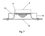
FIG. 7: the assembly wherein the curved trim body and a flat glass on a LED sink shown of a “downlight” or recessed ceiling design providing a connecting structure to the ceiling with springs.
FIG. 8: A lighting structure grouping LED modules with a built-in optical system.
FIG. 9: View of the luminaire's structure in FIG. 8 in cross section.
FIG. 10: Figure showing a distribution of rays of a COB LED type or an encapsulated LED, and a map of isolines associated with a height of 3 m on a flat of 5×5 m.
FIG. 11: Figure showing a distribution of rays of a COB LED type or an encapsulated LED, and a map of isolines associated with a height of 3 m on a flat of 5×5 m, identical to the previous figure, but with an integrated optical system.
FIG. 12: A distribution of LED rays similar than FIG. 11, with an optical system, and a plane associated illuminance.
FIG. 13: A distribution of LED rays similar than FIG. 11, with an optical system with filter, and a plane associated illuminance.
FIG. 14: A distribution of LED rays, with an optical system with filter and a partially translucent flat glass and an associated illuminance plane.
FIG. 15: A distribution of LED rays, with an optical system with filter and a translucent flat glass and an associated illuminance plane.
FIG. 16: A photometric graph of the optical system with asymmetrical lens.
FIG. 17: A photometric graph of the optical system with a corrugated flat convex lens.
FIG. 18: A photometric graph of an independent LED module with an optical system.
FIG. 19: A photometric graph of 5 LED modules an optical system.
DESCRIPTION OF THE INVENTION
The essential components of the LED optical of the invention are shown in FIG. 1, which includes a glass plano-convex type lens (1), with perimeter rim (2) on its circular base (3) a rubber seal (4) of matching size via which the lens is inserted.
Internal projections of the rubber seal formed by the circumferential groove are shown in the FIG. 2, both the upper protrusion (5) with an exact height required to achieve separation between the semiconductor LED and lens, as the lower protrusion (7), whose size is the same as the rim of the lens for perfect insertion.
Both figures also show the position of the adhesive disc-shaped filter (12), whose optional use eliminates the effect of chromatic aberration, stuck on the base of the lens, being inserted into the groove of the rubber gasket.
The glass lens can have different geometries, on which the luminaire photometry depends. The only thing that does not change in the lens design is the circular outline of its base and the perimeter rim insertion into the coupling joint, but both the shape of the base, as the shape and degree of curvature of the curved surface can change.
Two other specific lens designs are shown in FIG. 4, a corrugated base lens, and a perforated elliptical shaped inverted cone base.
The basic optical device created of glass lens with suitable geometry, with a rubber seal, with or without filter; it is integrated into the different types of luminaires and LED lamps, from industrial luminaires to “downlight” small LED, inserting the optics on the LED heat sink, by inside the trim crown body, since the pressure exerted on the inner side of the crown makes the device is perfectly retained. This allows it to be incorporated into luminaires installed in buildings, just removing the existing lens.
The position in which the optical is connected on the sink (8), around the LED semiconductor (6) is shown in FIG. 3. The trim body retaining element, which is fixed to the heatsink by holes provided in the base, is not shown in this figure, but the holes are shown.
It is necessary to focus on the preference implementation of the optical system with integrated trim body, according to the FIGS. 5, 6 and 7, where it is perfectly appreciated how the rubber seal and the lens inside the crown of the trim body (13) is placed; the trim body described above with a flat wing (16) and a straight (14) or curved side (15), folding in an inverted U shape (17) by the upper circumference edge, being inside where it is embedded and retained by pressure the rubber seal with the lens.
The joining of the trim body and the heat sink through screws in the threaded holes of the heat sink base is also shown in the FIGS. 5, 6 and 7.
The partially or completely translucent flat glass (18) supplementing the optical system in order to obtain an adequate light diffusion, of light is required for installation of indicated specific design of trim body, because the glass is mechanically fixed by screws or rivets, below the lower wing (16) of the cup-shaped crown.
The special design of the trim body made for the optics of the invention offers the possibility of manufacturing LED modules incorporating this optical advantageous.
A LED lamp or module like this will be constituted by a LED semiconductor with common heat sink, where the trim body is fixed, and the glass lens is fitted, with or without filter, through the rubber seal, optionally supplemented by special flat glass set under the wing of the trim body.
These LED modules with the described invention optic, may be used as individual points of light, integrated into ceilings and surfaces with appropriate means of installation, such as a clamping bridge (19) of the luminaire “downlight” shown in FIG. 7.
It is possible to set LED higher power luminaires structures, grouping modules, as shown in FIGS. 8 and 9, where a folded structure is grouping several LED modules, which are integrated through punched holes in the base with the same diameter of the trim module crown, which are fixed by the circular outstanding and coplanar wing to the structure.
This grouping modules system or individual lamps is great for manufacturing of industrial lighting modules with LED lighting technology.
Results Photometric Estudies:
The luminous efficiency can be improved compared to a LED luminaire without optics, up to 270% relative to a given working plane, such as a desk, modifying the geometry of the glass lens as the essential element of the optical system developed due the refraction effect of light rays.
Photometric studies conducted by DIALUX software, indicate this improvement. If the isolines plane, of the COB LED type or an encapsulated LED rays without optical shown in FIG. 10, are compared with the isolines plane that uses an optical lens of plano-convex glass symmetrically, shown in FIG. 11, the level of illumination of the second case, expressed in LUX, increases respect the first case.
The simulations with the same lens and a disc filter also show a decrease in luminous efficiency between 3 to 6%, depending on the filter, as a result of the elimination of chromatic aberration. For example, FIG. 12 shows the distribution of rays and the luminance plane associated with a LED with the same optical as above, with a symmetric lens plano-convex without filter, where the effect of chromatic aberration shown with an illumination more concentrated in the center of the lighting circle, compared with FIG. 13, showing a distribution of light and the luminance plane of a LED with the same lens but with the vinyl filter claimed of polished translucent polymeric material, where the chromatic defect has been eliminated and the light distribution is more homogeneous in the whole circle of illumination.
The effect on the diffusion of light produced by the optical system with special built flat glass has also been tested. If a LED luminaire with optics and with the same filter of the above type is added, a flat glass with a translucent side and a other transparent side, as part of the body of the trim, rays distribution of light and the luminance plane shown in the FIG. 14, which shows direct light concentrated at the center of the plane, and diffused light in the environment is generated, and using a translucent plane glass with the same optical, the distribution of the light and luminance plane of FIG. 15 is obtained, which shows only diffuse light.
In order to facilitate understanding of the two figures, the rays that are reflected in the flat glass to the trim body, which subsequently are reflected or transmitted through the plate glass, have been erased.
The different geometries of the lenses used in the invention produce different photometric curves; the light distribution curves, that show the relationship between the light intensity (CD/Klm, where K=1000), with the angle (in degrees) of the expansion of the light. For example, the FIG. 16 graph shows the photometric curve of the optical system with an asymmetric lens with the inner cavity of FIG. 4, and the FIG. 17 graph shows the photometric curve of the optical system with a corrugated base lens and convex surface of the same figure above.
In any case, for the same lens geometry, the photometry curve remains constant regardless of the number of lenses used, such as the LED clusters modules with the same optics in the industrial luminaires manufacture. The FIG. 19 graph shows the photometric curve for a group of five LED modules with optical system, and FIG. 18 shows the same photometric curve for one of these individual modules, confirming the advantages of modules groups to increase the light intensity for the same photometry.

Claims (6)

The invention claimed is:
1. An optical system for luminaires and LED lamps including a single-chip or multichip LED placed over a plate or encapsulated with a heat sink, and a crown shaped trim body attached to the heat sink and disposed around the semiconductor, the trim body including a vertically straight inner wall; wherein the optical system comprises: a glass lens having a circular lens base with a perimeter rim protruding outward from the lens base about an outermost circumference of the glass lens; and a rubber circular seal of a complementary size to the lens base, the rubber seal having a vertically straight outer side and an inner side including an internal slot in which the perimeter rim of lens is disposed, the inner side of the rubber seal further comprises an upper lip of suitable size to achieve a specified separation between the LED and the lens, and a lower lip of suitable size to collect the perimeter rim of the lens; the optical system being removably retained within the trim body only by pressure directly between the heat sink and the upper lip and pressure directly between the inner wall of the trim body and the outer side of the rubber seal.
2. The optical system for luminaires and LED lamps, according to claim 1, wherein the base of the glass lens has one of a smooth shape, a corrugated shape, an internal cavity, and different symmetrical or asymmetrical shapes; wherein an angular surface on the opposite side of the lens from the base has similar or different symmetrical or asymmetrical geometries.
3. The optical system for luminaires and LED lamps, according to claim 2, wherein the glass lens is a borosilicate lens having a plano-convex symmetrical geometry.
4. The optical system for luminaires and LED lamps, according to claim 3, wherein the glass lens has a translucent, disc-shaped, frosted polymeric vinyl self-adhesive filter superimposed on its base and including a rim, the filter inserted by its rim along the perimeter rim of the lens within the internal slot of the rubber seal.
5. The optical system for luminaires and LED lamps according to claim 1, wherein the trim body is formed by an external ring which has two geometric shapes as a top hat shape, or a curved shape, and a flat wing, folding in an inverted U shape that allows the connection by screws or other mechanical means of the trim body to d base of the heat sink by an upper circumference edge, the inner wall of the trim body extending vertically from the upper circumferential edge.
6. The optical system for luminaires and LED lamps according to claim 5, further comprising a transparent or translucent plate glass, fixed to the trim body below the lower wing.
US15/330,418 2014-04-22 2015-02-25 Optical system for luminaries and LED lighting Active US10066808B2 (en)

Applications Claiming Priority (4)

Application Number Priority Date Filing Date Title
ES201430592A ES2535586B2 (en) 2014-04-22 2014-04-22 Optical system for luminaires and LED lamps.
ES201430592 2014-04-22
ESP201430592 2014-04-22
PCT/ES2015/070134 WO2015162319A1 (en) 2014-04-22 2015-02-25 Optical system for led lamps and luminaires

Publications (2)

Publication Number Publication Date
US20170045198A1 US20170045198A1 (en) 2017-02-16
US10066808B2 true US10066808B2 (en) 2018-09-04

Family

ID=53029141

Family Applications (1)

Application Number Title Priority Date Filing Date
US15/330,418 Active US10066808B2 (en) 2014-04-22 2015-02-25 Optical system for luminaries and LED lighting

Country Status (10)

Country Link
US (1) US10066808B2 (en)
EP (1) EP3136455B1 (en)
BR (1) BR112016024249A2 (en)
CA (1) CA2950959A1 (en)
CL (1) CL2016002685A1 (en)
ES (1) ES2535586B2 (en)
MX (1) MX363257B (en)
PE (1) PE20161451A1 (en)
SA (1) SA516380077B1 (en)
WO (1) WO2015162319A1 (en)

Cited By (10)

* Cited by examiner, † Cited by third party
Publication number Priority date Publication date Assignee Title
US20190376676A1 (en) * 2018-06-12 2019-12-12 Stmicroelectronics (Research & Development) Limited Housing for light source
US20190376667A1 (en) * 2018-06-12 2019-12-12 Stmicroelectronics (Grenoble 2) Sas Protection mechanism for light source
US20200096181A1 (en) * 2014-11-15 2020-03-26 Selevan James R Sequential and coordinated flashing of electronic roadside flares with active energy conservation
US10777710B2 (en) 2018-06-12 2020-09-15 Stmicroelectronics (Grenoble 2) Sas Protection mechanism for light source
US10922987B2 (en) 2008-03-15 2021-02-16 James R. Selevan Sequenced guiding systems for vehicles and pedestrians
US10941921B2 (en) 2018-08-31 2021-03-09 Stmicroelectronics (Grenoble 2) Sas Protection mechanism for light source
US11013091B2 (en) 2017-07-06 2021-05-18 James R Selevan Devices and methods for synchronized signaling of the positions of moving pedestrians or vehicles
US11162650B2 (en) 2017-02-10 2021-11-02 James R. Selevan Portable electronic flare carrying case and system
US11211772B2 (en) 2018-06-12 2021-12-28 Stmicroelectronics (Grenoble 2) Sas Protection mechanism for light source
US11725785B2 (en) 2017-02-10 2023-08-15 James R. Selevan Portable electronic flare carrying case and system

Families Citing this family (6)

* Cited by examiner, † Cited by third party
Publication number Priority date Publication date Assignee Title
US10386058B1 (en) * 2016-03-17 2019-08-20 Shat-R-Shield, Inc. LED luminaire
US10767849B2 (en) 2016-04-25 2020-09-08 Shat-R-Shield, Inc. LED luminaire
CN107178718A (en) * 2017-07-22 2017-09-19 苏文藏 A kind of LED for supplementing luminosity
CN112577394A (en) * 2020-11-23 2021-03-30 无锡特恒科技有限公司 Sealing washer size rechecking device with reject function
CN216389418U (en) * 2021-10-22 2022-04-26 上海三思电子工程有限公司 LED ultraviolet sterilization device
CN115274639B (en) * 2022-08-17 2023-04-07 珠海市宏科光电子有限公司 Dimming and color-mixing integrated COB light source and processing technology thereof

Citations (11)

* Cited by examiner, † Cited by third party
Publication number Priority date Publication date Assignee Title
US5993029A (en) * 1997-04-07 1999-11-30 Chambers; Charles F. Lighting fixture globe attachment ring
US6203173B1 (en) * 1998-10-14 2001-03-20 Wet Enterprises, Inc. Lighting assembly having above water and underwater operational capabilities
US6435691B1 (en) * 1999-11-29 2002-08-20 Watkins Manufacturing Corporation Lighting apparatus for portable spas and the like
US7004600B2 (en) * 2002-06-12 2006-02-28 Echterling Kevin B Flashlight adapter
US20100002450A1 (en) * 2007-02-14 2010-01-07 Ledon Lighting Jennersdorf Gmbh Mounting Lenses for LED Modules
US20100309660A1 (en) * 2009-06-05 2010-12-09 Dong Nyung Lim Lighting device
US20110188244A1 (en) * 2009-05-25 2011-08-04 Sung Ho Hong Gap member, lens and lighting device having the same
US20130027917A1 (en) * 2011-07-26 2013-01-31 Shen Zhen Nibbe Optoelectronic Technology Co.,Ltd Led explosion-proof light
US20140211474A1 (en) * 2013-01-28 2014-07-31 Li-Hong Technological Co., Ltd. Energy-saving and explosion-proof led lamp
US20150369456A1 (en) * 2012-02-09 2015-12-24 Koninklijke Philips N.V. Releasable optical element
US9651224B1 (en) * 2014-01-17 2017-05-16 Paul Burgess Work light with variable voltage transformer and removable lens

Family Cites Families (7)

* Cited by examiner, † Cited by third party
Publication number Priority date Publication date Assignee Title
JP4013077B2 (en) * 2005-11-21 2007-11-28 松下電工株式会社 Light emitting device and manufacturing method thereof
US7804147B2 (en) * 2006-07-31 2010-09-28 Cree, Inc. Light emitting diode package element with internal meniscus for bubble free lens placement
ITPD20070426A1 (en) * 2007-12-21 2009-06-22 Minu Lamp Srl ILLUMINATING BODY WITH LENS
ES2310147B1 (en) * 2007-12-21 2009-11-05 Javier Fernandez De Valderrama Alvarez MODULAR DISPLAY LIGHT STATION.
CZ19871U1 (en) * 2009-06-05 2009-07-20 Cernoch@Jakub Light fitting
KR200448868Y1 (en) * 2009-09-22 2010-05-27 이재운 LED module for light
ES2351501B1 (en) * 2010-08-11 2011-12-12 Industrias De Iluminacion Roura, S.A. OPTICAL GROUP FOR LIGHTING OF PUBLIC LIGHTING.

Patent Citations (11)

* Cited by examiner, † Cited by third party
Publication number Priority date Publication date Assignee Title
US5993029A (en) * 1997-04-07 1999-11-30 Chambers; Charles F. Lighting fixture globe attachment ring
US6203173B1 (en) * 1998-10-14 2001-03-20 Wet Enterprises, Inc. Lighting assembly having above water and underwater operational capabilities
US6435691B1 (en) * 1999-11-29 2002-08-20 Watkins Manufacturing Corporation Lighting apparatus for portable spas and the like
US7004600B2 (en) * 2002-06-12 2006-02-28 Echterling Kevin B Flashlight adapter
US20100002450A1 (en) * 2007-02-14 2010-01-07 Ledon Lighting Jennersdorf Gmbh Mounting Lenses for LED Modules
US20110188244A1 (en) * 2009-05-25 2011-08-04 Sung Ho Hong Gap member, lens and lighting device having the same
US20100309660A1 (en) * 2009-06-05 2010-12-09 Dong Nyung Lim Lighting device
US20130027917A1 (en) * 2011-07-26 2013-01-31 Shen Zhen Nibbe Optoelectronic Technology Co.,Ltd Led explosion-proof light
US20150369456A1 (en) * 2012-02-09 2015-12-24 Koninklijke Philips N.V. Releasable optical element
US20140211474A1 (en) * 2013-01-28 2014-07-31 Li-Hong Technological Co., Ltd. Energy-saving and explosion-proof led lamp
US9651224B1 (en) * 2014-01-17 2017-05-16 Paul Burgess Work light with variable voltage transformer and removable lens

Cited By (17)

* Cited by examiner, † Cited by third party
Publication number Priority date Publication date Assignee Title
US11769418B2 (en) 2008-03-15 2023-09-26 James R. Selevan Sequenced guiding systems for vehicles and pedestrians
US10922987B2 (en) 2008-03-15 2021-02-16 James R. Selevan Sequenced guiding systems for vehicles and pedestrians
US11295625B2 (en) 2008-03-15 2022-04-05 James R. Selevan Sequenced guiding systems for vehicles and pedestrians
US20200096181A1 (en) * 2014-11-15 2020-03-26 Selevan James R Sequential and coordinated flashing of electronic roadside flares with active energy conservation
US11698186B2 (en) 2014-11-15 2023-07-11 James R. Selevan Sequential and coordinated flashing of electronic roadside flares with active energy conservation
US11313546B2 (en) 2014-11-15 2022-04-26 James R. Selevan Sequential and coordinated flashing of electronic roadside flares with active energy conservation
US11162650B2 (en) 2017-02-10 2021-11-02 James R. Selevan Portable electronic flare carrying case and system
US11725785B2 (en) 2017-02-10 2023-08-15 James R. Selevan Portable electronic flare carrying case and system
US11013091B2 (en) 2017-07-06 2021-05-18 James R Selevan Devices and methods for synchronized signaling of the positions of moving pedestrians or vehicles
US11706861B2 (en) 2017-07-06 2023-07-18 James R. Selevan Devices and methods for synchronized signaling of the positions of moving pedestrians or vehicles
US20190376676A1 (en) * 2018-06-12 2019-12-12 Stmicroelectronics (Research & Development) Limited Housing for light source
US11211772B2 (en) 2018-06-12 2021-12-28 Stmicroelectronics (Grenoble 2) Sas Protection mechanism for light source
US10865962B2 (en) * 2018-06-12 2020-12-15 Stmicroelectronics (Grenoble 2) Sas Protection mechanism for light source
US10777710B2 (en) 2018-06-12 2020-09-15 Stmicroelectronics (Grenoble 2) Sas Protection mechanism for light source
US10738985B2 (en) * 2018-06-12 2020-08-11 Stmicroelectronics (Research & Development) Limited Housing for light source
US20190376667A1 (en) * 2018-06-12 2019-12-12 Stmicroelectronics (Grenoble 2) Sas Protection mechanism for light source
US10941921B2 (en) 2018-08-31 2021-03-09 Stmicroelectronics (Grenoble 2) Sas Protection mechanism for light source

Also Published As

Publication number Publication date
EP3136455A4 (en) 2017-10-25
ES2535586R2 (en) 2015-11-12
ES2535586A2 (en) 2015-05-12
EP3136455A1 (en) 2017-03-01
WO2015162319A1 (en) 2015-10-29
US20170045198A1 (en) 2017-02-16
ES2535586B2 (en) 2016-04-27
MX363257B (en) 2019-03-19
MX2016013754A (en) 2017-04-06
BR112016024249A2 (en) 2017-08-15
EP3136455B1 (en) 2021-10-13
CA2950959A1 (en) 2015-10-29
CL2016002685A1 (en) 2017-06-02
SA516380077B1 (en) 2018-12-06
PE20161451A1 (en) 2017-02-03

Similar Documents

Publication Publication Date Title
US10066808B2 (en) Optical system for luminaries and LED lighting
CN108700273B (en) Lighting device
US7425084B2 (en) Bollard luminaire
CN108139062B (en) Illumination system and method of generating a light output
CN201368429Y (en) Illumination-direction-adjustable LED illuminating lamp with adjustable
CA2943130C (en) Field light control system for led luminaires
WO2020020078A1 (en) Easy-to-use led spotlight module
CN103206661A (en) G4 LED (light emitting diode) lamp
JP2012063762A (en) Lens and lamp using the same
CN206410034U (en) A kind of auto lamp lens module with multiple light focusing units
CN105402656B (en) LED spotlight structure
US20130114266A1 (en) Reflective unit and light source module having the same
EP2594978A1 (en) Reflective unit and light source module having the same
CN203363987U (en) Novel LED down lamp
CN103604094A (en) LED secondary lens device capable of generating multiple beam angles
CN218819926U (en) Double-lampshade pendant lamp
CN207599621U (en) Outdoor lighting lens
JP3172647U (en) Reflection unit and light source module thereof
CN203286455U (en) LEDG4 lamp
CN209055679U (en) Change the optical lens of light spot shape
KR101465182B1 (en) Reflection apparatus and lighting fixture having the same
AU2018266829B2 (en) Light source for a luminaire
CN101832504A (en) Diffusion light-guiding element
CN206875347U (en) A kind of control light Lamp cup for LED lamp
CN203784785U (en) Automotive lamp module

Legal Events

Date Code Title Description
STCF Information on status: patent grant

Free format text: PATENTED CASE

FEPP Fee payment procedure

Free format text: MAINTENANCE FEE REMINDER MAILED (ORIGINAL EVENT CODE: REM.); ENTITY STATUS OF PATENT OWNER: MICROENTITY

FEPP Fee payment procedure

Free format text: SURCHARGE FOR LATE PAYMENT, MICRO ENTITY (ORIGINAL EVENT CODE: M3554); ENTITY STATUS OF PATENT OWNER: MICROENTITY

MAFP Maintenance fee payment

Free format text: PAYMENT OF MAINTENANCE FEE, 4TH YEAR, MICRO ENTITY (ORIGINAL EVENT CODE: M3551); ENTITY STATUS OF PATENT OWNER: MICROENTITY

Year of fee payment: 4

AS Assignment

Owner name: FERRUIZ IP LLC, TEXAS

Free format text: ASSIGNMENT OF ASSIGNORS INTEREST;ASSIGNOR:RUIZ DE APODACA CARDENOSA, FERNANDO;REEL/FRAME:062277/0640

Effective date: 20221021