US10063174B2 - System and method for controlling a negative sequence current in a wind turbine generator - Google Patents
System and method for controlling a negative sequence current in a wind turbine generator Download PDFInfo
- Publication number
- US10063174B2 US10063174B2 US15/230,536 US201615230536A US10063174B2 US 10063174 B2 US10063174 B2 US 10063174B2 US 201615230536 A US201615230536 A US 201615230536A US 10063174 B2 US10063174 B2 US 10063174B2
- Authority
- US
- United States
- Prior art keywords
- negative sequence
- current
- power system
- electrical
- voltage
- Prior art date
- Legal status (The legal status is an assumption and is not a legal conclusion. Google has not performed a legal analysis and makes no representation as to the accuracy of the status listed.)
- Active, expires
Links
Images


Classifications
-
- H—ELECTRICITY
- H02—GENERATION; CONVERSION OR DISTRIBUTION OF ELECTRIC POWER
- H02P—CONTROL OR REGULATION OF ELECTRIC MOTORS, ELECTRIC GENERATORS OR DYNAMO-ELECTRIC CONVERTERS; CONTROLLING TRANSFORMERS, REACTORS OR CHOKE COILS
- H02P9/00—Arrangements for controlling electric generators for the purpose of obtaining a desired output
- H02P9/10—Control effected upon generator excitation circuit to reduce harmful effects of overloads or transients, e.g. sudden application of load, sudden removal of load, sudden change of load
-
- F—MECHANICAL ENGINEERING; LIGHTING; HEATING; WEAPONS; BLASTING
- F03—MACHINES OR ENGINES FOR LIQUIDS; WIND, SPRING, OR WEIGHT MOTORS; PRODUCING MECHANICAL POWER OR A REACTIVE PROPULSIVE THRUST, NOT OTHERWISE PROVIDED FOR
- F03D—WIND MOTORS
- F03D7/00—Controlling wind motors
- F03D7/02—Controlling wind motors the wind motors having rotation axis substantially parallel to the air flow entering the rotor
- F03D7/028—Controlling wind motors the wind motors having rotation axis substantially parallel to the air flow entering the rotor controlling wind motor output power
- F03D7/0284—Controlling wind motors the wind motors having rotation axis substantially parallel to the air flow entering the rotor controlling wind motor output power in relation to the state of the electric grid
-
- F—MECHANICAL ENGINEERING; LIGHTING; HEATING; WEAPONS; BLASTING
- F03—MACHINES OR ENGINES FOR LIQUIDS; WIND, SPRING, OR WEIGHT MOTORS; PRODUCING MECHANICAL POWER OR A REACTIVE PROPULSIVE THRUST, NOT OTHERWISE PROVIDED FOR
- F03D—WIND MOTORS
- F03D7/00—Controlling wind motors
- F03D7/02—Controlling wind motors the wind motors having rotation axis substantially parallel to the air flow entering the rotor
- F03D7/04—Automatic control; Regulation
- F03D7/042—Automatic control; Regulation by means of an electrical or electronic controller
- F03D7/043—Automatic control; Regulation by means of an electrical or electronic controller characterised by the type of control logic
- F03D7/044—Automatic control; Regulation by means of an electrical or electronic controller characterised by the type of control logic with PID control
-
- F03D9/003—
-
- F—MECHANICAL ENGINEERING; LIGHTING; HEATING; WEAPONS; BLASTING
- F03—MACHINES OR ENGINES FOR LIQUIDS; WIND, SPRING, OR WEIGHT MOTORS; PRODUCING MECHANICAL POWER OR A REACTIVE PROPULSIVE THRUST, NOT OTHERWISE PROVIDED FOR
- F03D—WIND MOTORS
- F03D9/00—Adaptations of wind motors for special use; Combinations of wind motors with apparatus driven thereby; Wind motors specially adapted for installation in particular locations
- F03D9/20—Wind motors characterised by the driven apparatus
- F03D9/25—Wind motors characterised by the driven apparatus the apparatus being an electrical generator
- F03D9/255—Wind motors characterised by the driven apparatus the apparatus being an electrical generator connected to electrical distribution networks; Arrangements therefor
-
- H—ELECTRICITY
- H02—GENERATION; CONVERSION OR DISTRIBUTION OF ELECTRIC POWER
- H02J—CIRCUIT ARRANGEMENTS OR SYSTEMS FOR SUPPLYING OR DISTRIBUTING ELECTRIC POWER; SYSTEMS FOR STORING ELECTRIC ENERGY
- H02J3/00—Circuit arrangements for AC mains or AC distribution networks
- H02J3/26—Arrangements for eliminating or reducing asymmetry in polyphase networks
-
- H—ELECTRICITY
- H02—GENERATION; CONVERSION OR DISTRIBUTION OF ELECTRIC POWER
- H02K—DYNAMO-ELECTRIC MACHINES
- H02K7/00—Arrangements for handling mechanical energy structurally associated with dynamo-electric machines, e.g. structural association with mechanical driving motors or auxiliary dynamo-electric machines
- H02K7/18—Structural association of electric generators with mechanical driving motors, e.g. with turbines
- H02K7/1807—Rotary generators
- H02K7/1823—Rotary generators structurally associated with turbines or similar engines
- H02K7/183—Rotary generators structurally associated with turbines or similar engines wherein the turbine is a wind turbine
-
- H—ELECTRICITY
- H02—GENERATION; CONVERSION OR DISTRIBUTION OF ELECTRIC POWER
- H02P—CONTROL OR REGULATION OF ELECTRIC MOTORS, ELECTRIC GENERATORS OR DYNAMO-ELECTRIC CONVERTERS; CONTROLLING TRANSFORMERS, REACTORS OR CHOKE COILS
- H02P9/00—Arrangements for controlling electric generators for the purpose of obtaining a desired output
- H02P9/007—Control circuits for doubly fed generators
-
- Y—GENERAL TAGGING OF NEW TECHNOLOGICAL DEVELOPMENTS; GENERAL TAGGING OF CROSS-SECTIONAL TECHNOLOGIES SPANNING OVER SEVERAL SECTIONS OF THE IPC; TECHNICAL SUBJECTS COVERED BY FORMER USPC CROSS-REFERENCE ART COLLECTIONS [XRACs] AND DIGESTS
- Y02—TECHNOLOGIES OR APPLICATIONS FOR MITIGATION OR ADAPTATION AGAINST CLIMATE CHANGE
- Y02E—REDUCTION OF GREENHOUSE GAS [GHG] EMISSIONS, RELATED TO ENERGY GENERATION, TRANSMISSION OR DISTRIBUTION
- Y02E10/00—Energy generation through renewable energy sources
- Y02E10/70—Wind energy
- Y02E10/72—Wind turbines with rotation axis in wind direction
-
- Y—GENERAL TAGGING OF NEW TECHNOLOGICAL DEVELOPMENTS; GENERAL TAGGING OF CROSS-SECTIONAL TECHNOLOGIES SPANNING OVER SEVERAL SECTIONS OF THE IPC; TECHNICAL SUBJECTS COVERED BY FORMER USPC CROSS-REFERENCE ART COLLECTIONS [XRACs] AND DIGESTS
- Y02—TECHNOLOGIES OR APPLICATIONS FOR MITIGATION OR ADAPTATION AGAINST CLIMATE CHANGE
- Y02E—REDUCTION OF GREENHOUSE GAS [GHG] EMISSIONS, RELATED TO ENERGY GENERATION, TRANSMISSION OR DISTRIBUTION
- Y02E40/00—Technologies for an efficient electrical power generation, transmission or distribution
- Y02E40/50—Arrangements for eliminating or reducing asymmetry in polyphase networks
Definitions
- the present disclosure relates generally to wind turbines and, more particularly, to a system and method for controlling a negative sequence current in a generator of a wind turbine.
- Wind power is considered one of the cleanest, most environmentally friendly energy sources presently available, and wind turbines have gained increased attention in this regard.
- a modern wind turbine typically includes a tower, generator, gearbox, nacelle, and one or more rotor blades.
- the rotor blades capture kinetic energy of wind using known airfoil principles.
- rotor blades typically have the cross-sectional profile of an airfoil such that, during operation, air flows over the blade producing a pressure difference between the sides. Consequently, a lift force, which is directed from a pressure side towards a suction side, acts on the blade. The lift force generates torque on the main rotor shaft, which is geared to a generator for producing electricity.
- the low-speed shaft is configured to drive the gearbox that subsequently steps up the low rotational speed of the low-speed shaft to drive a high-speed shaft at an increased rotational speed.
- the high-speed shaft is generally rotatably coupled to a generator so as to rotatably drive a generator rotor.
- a rotating magnetic field may be induced by the generator rotor and a voltage may be induced within a generator stator that is magnetically coupled to the generator rotor.
- the associated electrical power can be transmitted to a main transformer that is typically connected to a power grid via a grid breaker.
- the main transformer steps up the voltage amplitude of the electrical power such that the transformed electrical power may be further transmitted to the power grid.
- the generator may be electrically coupled to a bi-directional power converter that includes a rotor-side converter joined to a line-side converter via a regulated DC link.
- wind turbine power systems may include a variety of generator types, including but not limited to a doubly-fed asynchronous generator (DFAG).
- DFAG doubly-fed asynchronous generator
- DFAG operation is typically characterized in that the rotor circuit is supplied with current from a current-regulated power converter.
- the power converter can provide nearly instantaneous regulation of its output currents with respect to the grid frequency.
- the rotor-side converter controls the magnitude and phase of currents in the rotor circuit to achieve desired values of electromagnetic torque. Reactive power flow into the line-connected stator terminals of the generator can also be controlled.
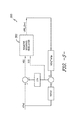
- FIG. 1 A simplified, schematic diagram of one embodiment of a main circuit 10 of a DFAG is illustrated in FIG. 1 .
- the main circuit 10 includes a generator 12 connected to a power converter 14 (as well as any required power electronics) and a transformer 16 that is connected to a power grid 18 . More specifically, as shown, the connection to the power grid 18 is at the high side of the transformer 16 , where the voltage and current are indicated as VG and IG, respectively. Further, the power grid 18 is illustrated conceptually as a Thevenin (Th) equivalent.
- Th Thevenin
- the Thevenin equivalent generally refers to an equivalent voltage source in series connection with an impedance that is an approximation of a complex, non-linear grid that constantly changes based on the number of wind turbines, external grid status, etc.
- Thevenin impedance ZTh varies with the number of wind turbines in operation and the status of the transmission system beyond the wind park.
- VTh a negative-sequence component of voltage appears in the Thevenin voltage, which is represented in FIG. 1 as VTh.
- VTh a negative-sequence component of voltage
- Such a negative sequence component of voltage can have a negative impact on the power grid 18 as well as the wind turbine power system.
- Prior art systems often design the control system to attenuate the negative sequence component of current flowing in the equipment as a result of the imbalance in the power grid 18 . While this reduces the duty on the equipment, it is not necessarily the best for the power system to which it is connected. As such, an improved system and method for providing negative-sequence control that causes the wind turbine to follow a prescribed relationship between the voltage VG and the current IG would be advantageous. For example, a negative-sequence control scheme that causes the relationship between the voltage VG and the current IG to be inductive nature, similar to how a directly-connected synchronous machine would react, would be desirable.
- the present disclosure is directed to controlling a negative sequence current in the DFAG of the wind turbine that addresses the aforementioned issues.
- the present subject matter is directed to a method for controlling an electrical power system connected to a power grid.
- the electrical power system has a power converter electrically coupled to a generator.
- the method includes determining, via a negative sequence regulator programmed in a controller of the electrical power system, a negative sequence component of at least one electrical condition of the electrical power system. Further, the method includes determining a desired current response based on the negative sequence component of the at least one electrical condition of the electrical power system. Thus, the method also includes determining a control command for the power converter as a function of the desired current response so as to achieve a desired relationship between a voltage condition in the power grid and the negative sequence component of the electrical condition of the electrical power system.
- control command may include a modulation index command for the power converter.
- method may also include determining the desired current response as a function of a desired negative sequence admittance characteristic of the electrical power system.
- the method may include estimating, via the negative sequence regulator programmed in the controller of the electrical power system, a negative sequence component of the voltage condition in the power grid as a function of the negative sequence component of the electrical condition of the generator and a grid parameter.
- the method may include determining at least one of a predictor current or a regulator current as a function of the estimated negative sequence component of the voltage condition in the power grid and the desired current response, determining a current output based on at least one of the predictor current or the regulator current, and determining the control command for the power converter as a function of the current output.
- the step of determining the regulator current may include applying a gain to an error signal representative of a difference between the desired current response and a measured current response, and integrating, via an integrator, the error signal to obtain the regulator current.
- the step of determining the predictor current may include multiplying the estimated negative sequence component of the voltage condition in the power grid and an uncompensated negative sequence admittance of the electrical power system, summing the multiplied value with the desired current response, filtering the summed value via a filter at a predetermined bandwidth, and applying a gain to the filtered value to obtain the predictor current.
- the method may include generating a compensation current based on the predictor current and a filtered compensator value.
- the method may include converting the current output to a voltage value and determining the modulation index command for the power converter as a function of the voltage value.
- the method may include dividing the voltage value by a DC link voltage from the power converter to obtain the modulation index command. In further embodiments, the method may include limiting the modulation index command for the power converter such that the modulation index command maintains relative values of the signal and does not cause windup.
- the electrical condition(s) of the power converter may include a voltage or a current of a stator of the generator, a rotor of the generator, a line-side converter of the power converter, a transformer of the electrical power system, or any other electrical conditions of the power system.
- the generator of the electrical power system may include a doubly-fed asynchronous generator (DFAG). Further, in certain embodiments, the electrical power system may be part of a wind turbine power system.
- DFAG doubly-fed asynchronous generator
- the present disclosure is directed to an electrical power system.
- the electrical power system includes a transformer connected to a power grid, a generator electrically coupled to the transformer, the generator comprising a rotor and a stator, a power converter electrically coupled to the transformer and the generator, and a controller configured to control the electrical power system. Further, the controller includes a negative sequence regulator programmed therein.
- the negative sequence regulator is configured to perform one or more operations, including but not limited to determining a negative sequence component of at least one electrical condition of the electrical power system, estimating a negative sequence component of a voltage condition in the power grid as a function of the negative sequence component of the electrical condition of the generator and a grid parameter, determining a desired current response based on the negative sequence component of the voltage condition in the power grid, and determining a control command for the power converter as a function of the desired current response so as to achieve a desired relationship between the negative sequence component of the voltage condition in the power grid and the negative sequence component of the electrical condition of the electrical power system.
- the electrical power system may further include any of the additional features as described herein.
- the present disclosure is directed to a method for reacting to a negative sequence voltage occurring in a power grid.
- the method includes determining, via a negative sequence regulator programmed in a controller of an electrical power system, a negative sequence component of at least one electrical condition of the electrical power system. Further, the method includes estimating, via the negative sequence regulator, a negative sequence component of a voltage condition in the power grid as a function of the negative sequence component of the electrical condition of the generator and a grid parameter. The method also includes determining a desired current response based on the negative sequence component of the voltage condition in the power grid.
- the method includes determining at least one of a predictor current and a regulator current as a function of the estimated negative sequence component of the voltage condition in the power grid and the desired current response.
- the method includes determining a current output based on at least one of the predictor current and the regulator current.
- the method also includes determining a modulation index command for the power converter as a function of the current output so as to achieve a desired relationship between the negative sequence component of the voltage condition in the power grid and the negative sequence component of the electrical condition of the electrical power system. It should be understood that the method may further include any of the additional steps and/or features as described herein.
- FIG. 1 illustrates a simplified schematic diagram of one embodiment of a main circuit according to the present disclosure
- FIG. 2 illustrates a perspective view of a portion of one embodiment of a wind turbine according to the present disclosure
- FIG. 3 illustrates a schematic view of one embodiment of an electrical power system suitable for use with the wind turbine shown in FIG. 2 ;
- FIG. 4 illustrates a block diagram of one embodiment of a controller suitable for use with the wind turbine shown in FIG. 2 ;
- FIG. 5 illustrates a schematic diagram of one embodiment of a control scheme according to the present disclosure, particularly illustrating a negative sequence regulator
- FIG. 6 illustrates a schematic diagram of one embodiment of a control scheme for sensing and transducing measured electrical signals to negative sequence components according to the present disclosure
- FIG. 7 illustrates a detailed, schematic diagram of one embodiment of a negative sequence regulator according to the present disclosure.
- the present subject matter is directed to a system and method for reacting to a negative sequence voltage occurring in a power grid. More specifically, the method includes determining, via a negative sequence regulator programmed in a controller of the electrical power system, a negative sequence component of at least one electrical condition of the electrical power system. Further, the method includes determining a desired current response based on the negative sequence component of the at least one electrical condition of the electrical power system. Thus, the method also includes determining a control command for the power converter as a function of the desired current response so as to achieve a desired relationship between a negative sequence component of the voltage condition in the power grid and the negative sequence component of the electrical condition of the electrical power system.
- FIG. 2 illustrates a perspective view of a portion of an exemplary wind turbine 100 according to the present disclosure that is configured to implement the method as described herein.
- the wind turbine 100 includes a nacelle 102 that typically houses a generator (not shown).
- the nacelle 102 is mounted on a tower 104 having any suitable height that facilitates operation of wind turbine 100 as described herein.
- the wind turbine 100 also includes a rotor 106 that includes three blades 108 attached to a rotating hub 110 .
- the wind turbine 100 may include any number of blades 108 that facilitates operation of the wind turbine 100 as described herein.
- FIG. 3 a schematic view of one embodiment of an electrical power system 200 that may be used with the wind turbine 100 is illustrated.
- wind impacts the blades 108 and the blades 108 transform wind energy into a mechanical rotational torque that rotatably drives a low-speed shaft 112 via the hub 110 .
- the low-speed shaft 112 is configured to drive a gearbox 114 that subsequently steps up the low rotational speed of the low-speed shaft 112 to drive a high-speed shaft 116 at an increased rotational speed.
- the high-speed shaft 116 is generally rotatably coupled to a generator 118 so as to rotatably drive a generator rotor 122 .
- the generator 118 may be a wound rotor, three-phase, doubly-fed induction (asynchronous) generator (DFAG) that includes a generator stator 120 magnetically coupled to a generator rotor 122 .
- DFAG doubly-fed induction
- a rotating magnetic field may be induced by the generator rotor 122 and a voltage may be induced within a generator stator 120 that is magnetically coupled to the generator rotor 122 .
- the generator 118 is configured to convert the rotational mechanical energy to a sinusoidal, three-phase alternating current (AC) electrical energy signal in the generator stator 120 .
- AC alternating current
- the associated electrical power can be transmitted to a main transformer 234 via a stator bus 208 , a stator synchronizing switch 206 , a system bus 216 , a main transformer circuit breaker 214 , and a generator-side bus 236 .
- the main transformer 234 steps up the voltage amplitude of the electrical power such that the transformed electrical power may be further transmitted to a grid via a grid circuit breaker 238 , a breaker-side bus 240 , and a grid bus 242 .
- the electrical power system 200 may include a wind turbine controller 202 configured to control any of the components of the wind turbine 100 and/or implement the method steps as described herein.
- the controller 202 may include one or more processor(s) 204 and associated memory device(s) 207 configured to perform a variety of computer-implemented functions (e.g., performing the methods, steps, calculations and the like and storing relevant data as disclosed herein).
- the controller 202 may also include a communications module 209 to facilitate communications between the controller 202 and the various components of the wind turbine 100 , e.g. any of the components of FIG. 3 .
- the communications module 209 may include a sensor interface 211 (e.g., one or more analog-to-digital converters) to permit signals transmitted from one or more sensors to be converted into signals that can be understood and processed by the processors 204 .
- the sensors e.g. sensors 252 , 254 , 256 , 258
- the communications module 209 may include any suitable means.
- the sensors 252 , 254 , 256 , 258 may be coupled to the sensor interface 211 via a wired connection.
- the sensors 252 , 254 , 256 , 258 may be coupled to the sensor interface 211 via a wireless connection, such as by using any suitable wireless communications protocol known in the art.
- the processor 204 may be configured to receive one or more signals from the sensors.
- processor refers not only to integrated circuits referred to in the art as being included in a computer, but also refers to a controller, a microcontroller, a microcomputer, a programmable logic controller (PLC), an application specific integrated circuit, and other programmable circuits.
- the processor 204 is also configured to compute advanced control algorithms and communicate to a variety of Ethernet or serial-based protocols (Modbus, OPC, CAN, etc.).
- the memory device(s) 207 may generally comprise memory element(s) including, but not limited to, computer readable medium (e.g., random access memory (RAM)), computer readable non-volatile medium (e.g., a flash memory), a floppy disk, a compact disc-read only memory (CD-ROM), a magneto-optical disk (MOD), a digital versatile disc (DVD) and/or other suitable memory elements.
- RAM random access memory
- computer readable non-volatile medium e.g., a flash memory
- CD-ROM compact disc-read only memory
- MOD magneto-optical disk
- DVD digital versatile disc
- Such memory device(s) 207 may generally be configured to store suitable computer-readable instructions that, when implemented by the processor(s) 204 , configure the controller 202 to perform the various functions as described herein.
- the generator stator 120 may be electrically coupled to a stator synchronizing switch 206 via a stator bus 208 .
- the generator rotor 122 may be electrically coupled to a bi-directional power conversion assembly 210 or power converter via a rotor bus 212 .
- the generator rotor 122 may be electrically coupled to the rotor bus 212 via any other device that facilitates operation of electrical power system 200 as described herein.
- the stator synchronizing switch 206 may be electrically coupled to a main transformer circuit breaker 214 via a system bus 216 .
- the power conversion assembly 210 may include a rotor filter 218 that is electrically coupled to the generator rotor 122 via the rotor bus 212 .
- the rotor filter 218 may include a rotor-side reactor.
- a rotor filter bus 219 electrically couples the rotor filter 218 to a rotor-side power converter 220 .
- the rotor-side power converter 220 may be electrically coupled to a line-side power converter 222 via a single direct current (DC) link 244 .
- the rotor-side power converter 220 and the line-side power converter 222 may be electrically coupled via individual and separate DC links.
- the DC link 244 may include a positive rail 246 , a negative rail 248 , and at least one capacitor 250 coupled therebetween.
- a line-side power converter bus 223 may electrically couple the line-side power converter 222 to a line filter 224 .
- a line bus 225 may electrically couple the line filter 224 to a line contactor 226 .
- the line filter 224 may include a line-side reactor.
- the line contactor 226 may be electrically coupled to a conversion circuit breaker 228 via a conversion circuit breaker bus 230 .
- the conversion circuit breaker 228 may be electrically coupled to the main transformer circuit breaker 214 via system bus 216 and a connection bus 232 .
- the main transformer circuit breaker 214 may be electrically coupled to an electric power main transformer 234 via a generator-side bus 236 .
- the main transformer 234 may be electrically coupled to a grid circuit breaker 238 via a breaker-side bus 240 .
- the grid circuit breaker 238 may be connected to the electric power transmission and distribution grid via a grid bus 242 .
- alternating current (AC) power generated at the generator stator 120 by rotation of the rotor 106 is provided via a dual path to the grid bus 242 .
- the dual paths are defined by the stator bus 208 and the rotor bus 212 .
- sinusoidal multi-phase (e.g. three-phase) AC power is provided to the power conversion assembly 210 .
- the rotor-side power converter 220 converts the AC power provided from the rotor bus 212 into DC power and provides the DC power to the DC link 244 .
- Switching elements e.g. IGBTs
- IGBTs used in bridge circuits of the rotor side power converter 220 can be modulated to convert the AC power provided from the rotor bus 212 into DC power suitable for the DC link 244 .
- the line side converter 222 converts the DC power on the DC link 244 into AC output power suitable for the electrical grid bus 242 .
- switching elements e.g. IGBTs
- the AC power from the power conversion assembly 210 can be combined with the power from the stator 120 to provide multi-phase power (e.g. three-phase power) having a frequency maintained substantially at the frequency of the electrical grid bus 242 (e.g. 50 Hz/60 Hz).
- multi-phase power e.g. three-phase power
- the rotor-side power converter 220 and the line-side power converter 222 may have any configuration using any switching devices that facilitate operation of electrical power system 200 as described herein.
- the power conversion assembly 210 may be coupled in electronic data communication with the turbine controller 202 and/or a separate or integral converter controller 262 to control the operation of the rotor-side power converter 220 and the line-side power converter 222 .
- the controller 202 may be configured to receive one or more voltage and/or electric current measurement signals from the first set of voltage and electric current sensors 252 .
- the controller 202 may be configured to monitor and control at least some of the operational variables associated with the wind turbine 100 via the sensors 252 .
- each of the sensors 252 may be electrically coupled to each one of the three phases of the power grid bus 242 .
- the sensors 252 may be electrically coupled to any portion of electrical power system 200 that facilitates operation of electrical power system 200 as described herein.
- the sensors may also include a second set of voltage and electric current sensors 254 , a third set of voltage and electric current sensors 256 , a fourth set of voltage and electric current sensors 258 (all shown in FIG. 2 ), and/or any other suitable sensors.
- any number or type of voltage and/or electric current sensors may be employed within the wind turbine 100 and at any location.
- the sensors may be current transformers, shunt sensors, rogowski coils, Hall Effect current sensors, Micro Inertial Measurement Units (MIMUs), or similar, and/or any other suitable voltage or electric current sensors now known or later developed in the art.
- MIMUs Micro Inertial Measurement Units
- the converter controller 262 is configured to receive one or more voltage and/or electric current feedback signals from the sensors 252 , 254 , 256 , 258 . More specifically, in certain embodiments, the current or voltage feedback signals may include at least one of line feedback signals, line-side converter feedback signals, rotor-side converter feedback signals, or stator feedback signals. For example, as shown in the illustrated embodiment, the converter controller 262 receives voltage and electric current measurement signals from the second set of voltage and electric current sensors 254 coupled in electronic data communication with stator bus 208 . The converter controller 262 may also receive the third and fourth set of voltage and electric current measurement signals from the third and fourth set of voltage and electric current sensors 256 , 258 .
- the converter controller 262 may be configured with any of the features described herein in regards to the main controller 202 . Further, the converter controller 262 may be separate from or integral with the main controller 202 . As such, the converter controller 262 is configured to implement the various method steps as described herein and may be configured similar to the turbine controller 202 .
- FIG. 5 illustrates a simplified, schematic diagram of one embodiment of a control scheme 300 according to the present disclosure, particularly illustrating a negative sequence regulator 302 ;
- FIG. 6 illustrates a schematic diagram of one embodiment of a control scheme 350 for sensing and transducing measured electrical signals to negative sequence components;
- FIG. 7 illustrates a detailed, schematic diagram of one embodiment of the negative sequence regulator 302 according to the present disclosure.
- the control scheme 300 includes a negative sequence regulator 302 applied to the power converter 210 .
- the variable names including a “2” represent the negative-sequence component of the associated variable.
- VTh2 represents the negative-sequence component of the grid Thevenin voltage VTh and so on.
- UR2_Cmd represents the negative-sequence component of the modulation index added to the modulation index contributions from other controls, e.g. the main rotor current regulator.
- the signals illustrated in the figures represent phasor quantities synchronized with the negative-sequence reference frame.
- Synchronization is based on the positive-sequence phase locked loop using double angle for demodulation and modulation.
- the voltage at the power grid (VG) and the current into the grid (IG) are assumed to be measured and transduced to extract the negative-sequence components (VG2 and IG2), which is further discussed with reference to FIG. 6 below.
- the negative sequence component of the grid voltage VTh2 and the control command UR2_Cmd contribute independently to the measured IG2.
- the net effect of the system impedances and control reactions can be represented via two admittance terms, namely YGTh2 and YGR2.
- the admittances YGTh2 and YGR2 are functions of the impedances of the machine, the transformer 234 , filters, external grid (ZTh), etc. Further, the admittances YGTh2 and YGR2 are a function of the main current regulators of the rotor-side and line-side converters 220 , 222 and the DC voltage regulator. As such, the admittances YGTh2 and YGR2 vary with operating conditions, such as speed and flux in the machine.
- Equations (1) and (2) provide one embodiment of methods for calculating the admittances YGTh2 and YGR2 from tests and then compensating for ZTh.
- the admittance terms represent the net effect of the inherent machine impedance (including controls) in series with ZTh.
- the electrical signals or conditions may include a voltage or a current of a stator of the generator (VS, IS), a voltage or a current of a rotor of the generator (VR, IR), a voltage or a current of a line-side converter of the power converter (VL, IL), a voltage or a current of a transformer of the electrical power system (VG, IG), or any other electrical conditions of the power system.
- a stator of the generator VS, IS
- VR, IR voltage or a current of a rotor of the generator
- VL, IL line-side converter of the power converter
- VG, IG transformer of the electrical power system
- the stator voltage VS, the stator current IS, and the line-side converter current IL are being transduced.
- stator voltage VS, the stator current IS, and the line-side converter current IL are used to estimate the voltage at the high-side of the transformer VG at block 352 .
- block 354 provides a turn ratio for the line-side converter current IL such that the two currents can be summed at 356 .
- the voltage at the high-side of the transformer VG and the summed currents can then be fed to one or more positive/negative (pos/neg) discriminator(s) 358 , 360 .
- a phase locked loop angle ⁇ pll can be factored into the pos/neg discriminator(s) 358 , 360 .
- the output of the positive/negative (pos/neg) discriminator(s) 358 , 360 are equal to VG2_fbk and IG2_fbk, respectively. It should also be understood that VG2_fbk and IG2_fbk may be measured directly and FIG. 6 is provided for illustrative purposes only.
- the negative sequence regulator 302 is configured to determine a negative sequence component (e.g. VG2_Fbk, IG2_Fbk) of at least one electrical condition (e.g. VG, IG, VS, IS, VR, IR, VL, IL) of the electrical power system 200 .
- a negative sequence component e.g. VG2_Fbk, IG2_Fbk
- the inputs to the negative sequence regulator 302 correspond to the negative sequence component of the grid voltage and current (e.g. VG2_Fbk, IG2_Fbk).
- the negative sequence regulator 302 is configured to determine a regulator current (IG2_Reg) as a function of the estimated negative sequence component of the voltage condition in the power grid 242 (VTh2_Fbk) and a desired current response (IG2_Cmd).
- IG2_Reg regulator current
- IG2_Cmd desired current response
- the negative sequence regulator 302 may be configured to determine the desired current response IG2_Cmd as a function of the estimated negative sequence component of the voltage condition in the power grid 242 VTh2_Fbk and a desired negative sequence admittance characteristic of the electrical power system (Y2RefTh).
- the reference for IG2 is determined based on the measured value of VTh2, the value of ZTh used in computing VTh2, and the desired admittance as seen from VG looking into the wind turbine transformer 234 . As such, when the negative sequence regulator 302 forces the actual IG2 currents to equal the reference, the effect of ZTh is cancelled. However, the use of a remote voltage closer to the true source is to reduce interactions with the grid 242 that can lead to instability, thereby permitting faster response.
- Y 2 RefTh Y 2 Ref /(1+ Y 2 Ref*ZTh ) Equation (5)
- Y2Ref is the desired admittance looking into the system from VG
- Y2RefTh is the desired admittance looking into the system from VTh.
- Equations (6)-(8) below further simplify Equations (4) and (5) above.
- Y 2 Ref jB 2 ref Equation (6)
- ZTh jXTh Equation (7)
- Y 2 RefTh jB 2 ref /(1 ⁇ B 2 Ref*XTh ) Equation (8)
- B2Ref is a negative number for inductive.
- Such a requirement is generally provided as a gain representing the magnitude of IG2 to be supplied as a function of the voltage at VG2, in per unit.
- the value of B2Ref follows from this gain. If the control is implemented in per unit then Zbase is one, and can be represented as shown in below in Equations (9) and (10).
- IG 2_Spec IG 2_ Gn ( VG 2)* VG 2 Equation (9)
- B 2 Ref ⁇ IG 2_ Gn/Z base Equation (10)
- the negative sequence regulator 302 is configured to determine the regulator current (IG2_Reg) by applying a gain (IG2_BW) to an error signal representative of a difference between the desired current response (IG2_Cmd) and a measured current response and integrating, via an integrator 310 , the error signal to obtain the regulator current IG2_Reg. More specifically, the structure is to create a signal IG2_Reg that would be processed to create approximately the same amount of IG2_Fbk. With this structure, the gain in the corrector path IG2_BW represents its bandwidth.
- the negative sequence regulator 302 is configured to determine a predictor current (IG2FF_Final) as a function of the estimated negative sequence component of the voltage condition in the power grid (VTh2_Fbk). As such, the predictor current IG2FF_Final provides a value for the regulator output that would, if perfect, bring the actual current to the commanded value. This is the feedforward component of the control command UR2_Cmd.
- the negative sequence regulator 302 may determine the predictor current (IG2FF_Final) by multiplying the estimated negative sequence component of the voltage condition in the power grid 242 (VTh2_Fbk) and an uncompensated negative sequence admittance of the electrical power system 200 (YGTh2), summing the multiplied value with the desired current response (IG2_Cmd), filtering the summed value (IG2FF_WFlt) via a filter 304 at a predetermined bandwidth (IG2FF_Flt).
- the filter 304 e.g. a low-pass filter
- the filter 304 is provided in the structure as a means to attenuate high-frequency noise.
- the filter bandwidth IGFF_Wfilt may be high, e.g. above 300 r/s.
- the negative sequence regulator 302 may limit the filtered value (IG2FF_Flt) at block 306 via a gain (IG2FF_Gn) to obtain the predictor current IG2FF_Final.
- the gain IG2FF_Gn would be set to a value less than unity, e.g. 0.8, and adjusted as needed.
- the negative sequence regulator 302 may also be configured to generate a compensation current (IGFF_Comp) to reduce the tendency of the predictor to overreact. Further, as shown, the negative sequence regulator 302 may be configured to generate a compensator value (IGFF_WComp) via a filter 314 . More specifically, in certain embodiments, this function may use a low-pass filter on the final feed-forward output (IG2FF_Wcomp) to estimate the delay before seeing the reaction in IG2_Fbk. This time delay would be seen in the tests performed to measure YGR2. As such, the negative sequence regulator 302 may be configured to generate the compensation current IGFF_Comp based on the predictor current IG2FF_Final and the filtered compensator value (IGFF_WComp).
- the negative sequence regulator 302 is further configured to determine a current output (IG2_Tot) based on the predictor current (IG2FF_Final) and the regulator current (IG2_Reg). More specifically, as shown at 312 , the negative sequence regulator 302 may be configured to determine the current output IG2_Tot by summing the predictor current IG2FF_Final and the regulator current IG2_Reg, which represents the value of IG2 that the regulator is asking for, assuming the subsequent processing is perfect.
- the negative sequence regulator 302 is also configured to determine a control command (UR2_Cmd) for the power converter 210 as a function of the current output (IG2_Tot) so as to achieve a desired relationship between the negative sequence component of the voltage condition in the power grid (VTh2_Fbk) and the negative sequence component of the electrical condition of the generator 118 (IG2_Fbk), e.g. the negative sequence component of current.
- the control command UR2_Cmd may include a modulation index command (UR2_Cmd) for the power converter 210 .
- the negative sequence regulator 302 may be further configured to convert the current output IG2_Tot to a voltage value (VR2_Tot) via one or more post-processing steps as shown at 316 .
- the subsequent processing is completed via a complex gain ZGR2, which is an estimate of the inverse of YGR2.
- the negative sequence regulator 302 is configured to determine the modulation index command UR2_Cmd for the power converter 210 as a function of the voltage value VR2_Tot.
- a phase trim feature can be included in the calculation of ZGR2 to allow for tuning as the phase of this function can be more important to stability than the gain.
- the negative sequence regulator 302 may also be configured to divide the voltage value VR2_Tot by a DC link voltage (Vdc_Fbk) of the power converter 210 to obtain the modulation index command (UR2_Cmd).
- the negative sequence regulator 302 may convert the current output IG2_Tot to the appropriate modulation index by using ZGR2 and/or by dividing by VrGn, which represents a change in units from the modulation index to per-unit voltage, which depends on the measured DC voltage and the base rotor voltage (i.e. line to line RMS value), as shown in Equation (12) below:
- VrGn Vdc _ Fbk /(sqrt(2)* VR BASE) Equation (12)
- the negative sequence regulator 302 may also include a limit logic 320 configured to limit the modulation index command UR2_Cmd for the power converter 210 such that the modulation index command UR2_Cmd does not cause windup. More specifically, the above steps create can create an unlimited value of the modulation index command (UR2_Unlim). If the magnitude of UR2_Unlim exceeds the limit allocated for negative-sequence component then limiting is required. As such, the limit logic 320 is configured to restrict the components of UR2 such that the phase relationship of the real and imaginary components is retained. More specifically, each of the signals illustrated in FIGS. 5-7 represent complex numbers having real and imaginary components.
- the limit logic 320 is configured to limit the modulation index command for the power converter 210 such that the modulation index command maintains the relative values of the two components of the signal (i.e. real and imaginary).
- the limit logic 320 may compute a factor that is used as a multiplier in appropriate locations.
- the factor may be applied similarly to modify their outputs before executing the next pass, as shown in Equations (15) and (16) below:
- IG 2 Reg IG 2 Reg*UR 2 Lim Factor Equation (15)
- IG 2 FF _ Filt IG 2 FF _ Filt*UR 2 Lim Factor Equation (16)
- the present disclosure provides negative-sequence control that causes the electrical power system (e.g. the wind turbine power system 200 of FIG. 3 ) to follow a prescribed relationship between the voltage VG and the current IG.
- the electrical power system e.g. the wind turbine power system 200 of FIG. 3
Landscapes
- Engineering & Computer Science (AREA)
- Power Engineering (AREA)
- Life Sciences & Earth Sciences (AREA)
- Sustainable Development (AREA)
- Sustainable Energy (AREA)
- Chemical & Material Sciences (AREA)
- Combustion & Propulsion (AREA)
- Mechanical Engineering (AREA)
- General Engineering & Computer Science (AREA)
- Control Of Eletrric Generators (AREA)
Abstract
Description
ZGTh2=1/YGTh2=ZGTh2o+ZTh Equation (1)
ZGR2=1/YGR2=ZGR2o+ZTh Equation (2)
where
ZGTh2o is equal to 1/YGTh2 when ZTh=0, and
ZGR2o is equal to 1/YGR2 when ZTh=0.
VTh2_Fbk=VG2_Fbk−ZTh*IG2_Fbk Equation (3)
IG2_Cmd=−VTh2_Fbk*Y2RefTh Equation (4)
Y2RefTh=Y2Ref/(1+Y2Ref*ZTh) Equation (5)
where
Y2Ref is the desired admittance looking into the system from VG, and
Y2RefTh is the desired admittance looking into the system from VTh.
Y2Ref=jB2ref Equation (6)
ZTh=jXTh Equation (7)
Y2RefTh=jB2ref/(1−B2Ref*XTh) Equation (8)
where
B2Ref is a negative number for inductive.
IG2_Spec=IG2_Gn(VG2)*VG2 Equation (9)
B2Ref=−IG2_Gn/Zbase Equation (10)
ZGR2=1/YGR2_avg*exp(jThetaZGR2trim) Equation (11)
where
YGR2_avg is the average of YGR2 measurements over the desired operating range, and
ThetaZGR2trim is the angle to shift from YGR2_avg.
VrGn=Vdc_Fbk/(sqrt(2)*VRBASE) Equation (12)
UR2LimFactor=min(1.0,UR2Lim/sqrt(UR2x_Unlim^2+UR2y_Unlim^2)) Equation (13)
UR2_Cmd=UR2_Unlim*UR2LimFactor Equation (14)
IG2Reg=IG2Reg*UR2LimFactor Equation (15)
IG2FF_Filt=IG2FF_Filt*UR2LimFactor Equation (16)
Claims (15)
Priority Applications (4)
| Application Number | Priority Date | Filing Date | Title |
|---|---|---|---|
| US15/230,536 US10063174B2 (en) | 2016-08-08 | 2016-08-08 | System and method for controlling a negative sequence current in a wind turbine generator |
| EP17184804.7A EP3282538B1 (en) | 2016-08-08 | 2017-08-03 | System and method for controlling a negative sequence current in a wind turbine generator |
| DK17184804.7T DK3282538T3 (en) | 2016-08-08 | 2017-08-03 | SYSTEM AND METHOD OF CONTROLING A NEGATIVE SEQUENCE CURRENT IN A WIND TURBINE GENERATOR |
| ES17184804T ES2808927T3 (en) | 2016-08-08 | 2017-08-03 | System and procedure to control a negative sequence current in a wind turbine generator |
Applications Claiming Priority (1)
| Application Number | Priority Date | Filing Date | Title |
|---|---|---|---|
| US15/230,536 US10063174B2 (en) | 2016-08-08 | 2016-08-08 | System and method for controlling a negative sequence current in a wind turbine generator |
Publications (2)
| Publication Number | Publication Date |
|---|---|
| US20180041154A1 US20180041154A1 (en) | 2018-02-08 |
| US10063174B2 true US10063174B2 (en) | 2018-08-28 |
Family
ID=59523028
Family Applications (1)
| Application Number | Title | Priority Date | Filing Date |
|---|---|---|---|
| US15/230,536 Active 2036-08-18 US10063174B2 (en) | 2016-08-08 | 2016-08-08 | System and method for controlling a negative sequence current in a wind turbine generator |
Country Status (4)
| Country | Link |
|---|---|
| US (1) | US10063174B2 (en) |
| EP (1) | EP3282538B1 (en) |
| DK (1) | DK3282538T3 (en) |
| ES (1) | ES2808927T3 (en) |
Families Citing this family (4)
| Publication number | Priority date | Publication date | Assignee | Title |
|---|---|---|---|---|
| US10731628B1 (en) * | 2019-05-06 | 2020-08-04 | General Electric Company | System and method for coordinated control of reactive power from a generator and a reactive power compensation device in a wind turbine system |
| US11231014B2 (en) | 2020-06-22 | 2022-01-25 | General Electric Company | System and method for reducing voltage distortion from an inverter-based resource |
| CN116227154B (en) * | 2023-01-09 | 2024-03-08 | 华能苏州热电有限责任公司 | Method for establishing high-low speed motor and variable frequency motor model under circulating pump working frequency |
| WO2025128122A1 (en) * | 2023-12-15 | 2025-06-19 | Ge Infrastructure Technology Llc | System and method for reducing grid current imbalance in an electrical power system |
Citations (13)
| Publication number | Priority date | Publication date | Assignee | Title |
|---|---|---|---|---|
| US20070177314A1 (en) * | 2006-01-31 | 2007-08-02 | Haiqing Weng | Method, apparatus and computer program product for injection current |
| US20100052322A1 (en) * | 2006-11-20 | 2010-03-04 | Repower Systems Ag | Wind energy installation with negative sequence system regulation and operating method |
| US20110215775A1 (en) * | 2008-09-11 | 2011-09-08 | Woodward Kempen Gmbh | Direct power control with component separation |
| US20120119712A1 (en) * | 2010-11-17 | 2012-05-17 | Abb Oy | Control method for doubly-fed electric generator |
| US20120299305A1 (en) * | 2011-05-26 | 2012-11-29 | Paul Brian Brogan | Method and System for Operating and Controlling a Wind Turbine to Prevent Excitation of Subsynchronous Oscillations within the Wind Turbine |
| US20130057297A1 (en) * | 2010-05-28 | 2013-03-07 | Zhongyuan Cheng | Method and apparatus for detecting power converter capacitor degradation using negative sequence currents |
| US20130121046A1 (en) * | 2011-11-10 | 2013-05-16 | Delta Electronics (Shanghai) Co., Ltd. | Phase locking system for three-phase alternating current electric grid and method thereof |
| US20130234435A1 (en) * | 2012-03-09 | 2013-09-12 | Robert Gregory Wagoner | Method and systems for operating a wind turbine |
| US20130264824A1 (en) * | 2010-11-10 | 2013-10-10 | Vestas Wind Systems A/S | Method for operating a power generation system |
| US20130320936A1 (en) * | 2012-06-05 | 2013-12-05 | Heng Deng | Current controller and generator system |
| US20140138949A1 (en) * | 2012-04-24 | 2014-05-22 | Masdar Institute Of Science And Technology | Fault handling system for doubly fed induction generator |
| US20140307488A1 (en) * | 2013-04-16 | 2014-10-16 | Siemens Aktiengesellschaft | Controller for controlling a power converter |
| US20150300320A1 (en) * | 2012-11-12 | 2015-10-22 | Wobben Properties Gmbh | Wind power installation and method for injecting electrical energy |
-
2016
- 2016-08-08 US US15/230,536 patent/US10063174B2/en active Active
-
2017
- 2017-08-03 ES ES17184804T patent/ES2808927T3/en active Active
- 2017-08-03 EP EP17184804.7A patent/EP3282538B1/en active Active
- 2017-08-03 DK DK17184804.7T patent/DK3282538T3/en active
Patent Citations (14)
| Publication number | Priority date | Publication date | Assignee | Title |
|---|---|---|---|---|
| US20070177314A1 (en) * | 2006-01-31 | 2007-08-02 | Haiqing Weng | Method, apparatus and computer program product for injection current |
| US20100052322A1 (en) * | 2006-11-20 | 2010-03-04 | Repower Systems Ag | Wind energy installation with negative sequence system regulation and operating method |
| US20110215775A1 (en) * | 2008-09-11 | 2011-09-08 | Woodward Kempen Gmbh | Direct power control with component separation |
| US20130057297A1 (en) * | 2010-05-28 | 2013-03-07 | Zhongyuan Cheng | Method and apparatus for detecting power converter capacitor degradation using negative sequence currents |
| US20130264824A1 (en) * | 2010-11-10 | 2013-10-10 | Vestas Wind Systems A/S | Method for operating a power generation system |
| US9702908B2 (en) * | 2010-11-10 | 2017-07-11 | Vestas Wind Systems A/S | Method for operating a power generation system |
| US20120119712A1 (en) * | 2010-11-17 | 2012-05-17 | Abb Oy | Control method for doubly-fed electric generator |
| US20120299305A1 (en) * | 2011-05-26 | 2012-11-29 | Paul Brian Brogan | Method and System for Operating and Controlling a Wind Turbine to Prevent Excitation of Subsynchronous Oscillations within the Wind Turbine |
| US20130121046A1 (en) * | 2011-11-10 | 2013-05-16 | Delta Electronics (Shanghai) Co., Ltd. | Phase locking system for three-phase alternating current electric grid and method thereof |
| US20130234435A1 (en) * | 2012-03-09 | 2013-09-12 | Robert Gregory Wagoner | Method and systems for operating a wind turbine |
| US20140138949A1 (en) * | 2012-04-24 | 2014-05-22 | Masdar Institute Of Science And Technology | Fault handling system for doubly fed induction generator |
| US20130320936A1 (en) * | 2012-06-05 | 2013-12-05 | Heng Deng | Current controller and generator system |
| US20150300320A1 (en) * | 2012-11-12 | 2015-10-22 | Wobben Properties Gmbh | Wind power installation and method for injecting electrical energy |
| US20140307488A1 (en) * | 2013-04-16 | 2014-10-16 | Siemens Aktiengesellschaft | Controller for controlling a power converter |
Non-Patent Citations (2)
| Title |
|---|
| Extended European Search Report and Opinion issued in connection with corresponding EP Application No. 17184804.7 dated Dec. 14, 2017. |
| Nian, H., et al., "Voltage Imbalance Compensation for Doubly Fed Induction Generator Using Direct Resonant Feedback Regulator," IEEE Transactions on Energy Conversion, vol. 31, No. 2, pp. 614-626 (Jun. 1, 2016). |
Also Published As
| Publication number | Publication date |
|---|---|
| US20180041154A1 (en) | 2018-02-08 |
| EP3282538A1 (en) | 2018-02-14 |
| DK3282538T3 (en) | 2020-08-17 |
| ES2808927T3 (en) | 2021-03-02 |
| EP3282538B1 (en) | 2020-05-13 |
Similar Documents
| Publication | Publication Date | Title |
|---|---|---|
| US10491146B2 (en) | System and method for compensating for generator-induced flicker in a wind turbine | |
| US7656052B2 (en) | Power converters | |
| CA2629179C (en) | Power converters | |
| US9252601B2 (en) | Method for controlling a power converter in a wind turbine generator | |
| US7372174B2 (en) | Power converters | |
| CN113454868B (en) | Virtual synchronous generator with active damping | |
| US10707789B2 (en) | Adaptive current damping module for improved power converter control in wind turbine systems | |
| EP3276819B1 (en) | Electrical power circuit and method of operating same | |
| EP3282538B1 (en) | System and method for controlling a negative sequence current in a wind turbine generator | |
| EP3614520B1 (en) | Systems and methods for controlling electrical power systems connected to a power grid | |
| Guerrero et al. | Accurate rotor speed estimation for low-power wind turbines | |
| EP2768134A1 (en) | Voltage control for a generator of a wind turbine | |
| WO2019051771A1 (en) | Systems and methods for controlling electrical power systems connected to power grid | |
| Chandran et al. | Power quality improvement for PMSG based isolated small hydro system feeding three-phase 4-wire unbalanced nonlinear loads | |
| KR100768040B1 (en) | Winding type induction generator controller with automatic grid linkage | |
| US20240305227A1 (en) | Dynamically obtaining maximum capacities in a dfim electric drive | |
| EP3742570B1 (en) | System and method for mitigating flicker in a power grid from a wind turbine power system | |
| Guerrero et al. | Sensorless speed control of a small wind turbine using the rectifier voltage ripple | |
| Rathnayake et al. | Torque ripple minimization of an IPMSG with fractional-slot, concentrated-winding using uncontrolled rectifier-connected boost converter control |
Legal Events
| Date | Code | Title | Description |
|---|---|---|---|
| AS | Assignment |
Owner name: GENERAL ELECTRIC COMPANY, NEW YORK Free format text: ASSIGNMENT OF ASSIGNORS INTEREST;ASSIGNORS:LARSEN, EINAR VAUGHN;REN, WEI;HOWARD, DUSTIN;AND OTHERS;SIGNING DATES FROM 20160804 TO 20160805;REEL/FRAME:039361/0694 |
|
| STCF | Information on status: patent grant |
Free format text: PATENTED CASE |
|
| MAFP | Maintenance fee payment |
Free format text: PAYMENT OF MAINTENANCE FEE, 4TH YEAR, LARGE ENTITY (ORIGINAL EVENT CODE: M1551); ENTITY STATUS OF PATENT OWNER: LARGE ENTITY Year of fee payment: 4 |
|
| AS | Assignment |
Owner name: GE INFRASTRUCTURE TECHNOLOGY LLC, SOUTH CAROLINA Free format text: ASSIGNMENT OF ASSIGNORS INTEREST;ASSIGNOR:GENERAL ELECTRIC COMPANY;REEL/FRAME:065727/0001 Effective date: 20231110 Owner name: GE INFRASTRUCTURE TECHNOLOGY LLC, SOUTH CAROLINA Free format text: ASSIGNMENT OF ASSIGNOR'S INTEREST;ASSIGNOR:GENERAL ELECTRIC COMPANY;REEL/FRAME:065727/0001 Effective date: 20231110 |
|
| MAFP | Maintenance fee payment |
Free format text: PAYMENT OF MAINTENANCE FEE, 8TH YEAR, LARGE ENTITY (ORIGINAL EVENT CODE: M1552); ENTITY STATUS OF PATENT OWNER: LARGE ENTITY Year of fee payment: 8 |