US10061257B2 - Image forming apparatus - Google Patents
Image forming apparatus Download PDFInfo
- Publication number
- US10061257B2 US10061257B2 US15/647,606 US201715647606A US10061257B2 US 10061257 B2 US10061257 B2 US 10061257B2 US 201715647606 A US201715647606 A US 201715647606A US 10061257 B2 US10061257 B2 US 10061257B2
- Authority
- US
- United States
- Prior art keywords
- error
- display
- log information
- unit
- display unit
- Prior art date
- Legal status (The legal status is an assumption and is not a legal conclusion. Google has not performed a legal analysis and makes no representation as to the accuracy of the status listed.)
- Active
Links
Images


Classifications
-
- G—PHYSICS
- G03—PHOTOGRAPHY; CINEMATOGRAPHY; ANALOGOUS TECHNIQUES USING WAVES OTHER THAN OPTICAL WAVES; ELECTROGRAPHY; HOLOGRAPHY
- G03G—ELECTROGRAPHY; ELECTROPHOTOGRAPHY; MAGNETOGRAPHY
- G03G15/00—Apparatus for electrographic processes using a charge pattern
- G03G15/70—Detecting malfunctions relating to paper handling, e.g. jams
-
- H—ELECTRICITY
- H04—ELECTRIC COMMUNICATION TECHNIQUE
- H04N—PICTORIAL COMMUNICATION, e.g. TELEVISION
- H04N1/00—Scanning, transmission or reproduction of documents or the like, e.g. facsimile transmission; Details thereof
- H04N1/00002—Diagnosis, testing or measuring; Detecting, analysing or monitoring not otherwise provided for
- H04N1/00026—Methods therefor
- H04N1/00037—Detecting, i.e. determining the occurrence of a predetermined state
-
- B—PERFORMING OPERATIONS; TRANSPORTING
- B41—PRINTING; LINING MACHINES; TYPEWRITERS; STAMPS
- B41J—TYPEWRITERS; SELECTIVE PRINTING MECHANISMS, i.e. MECHANISMS PRINTING OTHERWISE THAN FROM A FORME; CORRECTION OF TYPOGRAPHICAL ERRORS
- B41J11/00—Devices or arrangements of selective printing mechanisms, e.g. ink-jet printers or thermal printers, for supporting or handling copy material in sheet or web form
- B41J11/006—Means for preventing paper jams or for facilitating their removal
-
- G—PHYSICS
- G03—PHOTOGRAPHY; CINEMATOGRAPHY; ANALOGOUS TECHNIQUES USING WAVES OTHER THAN OPTICAL WAVES; ELECTROGRAPHY; HOLOGRAPHY
- G03G—ELECTROGRAPHY; ELECTROPHOTOGRAPHY; MAGNETOGRAPHY
- G03G15/00—Apparatus for electrographic processes using a charge pattern
- G03G15/50—Machine control of apparatus for electrographic processes using a charge pattern, e.g. regulating differents parts of the machine, multimode copiers, microprocessor control
- G03G15/5016—User-machine interface; Display panels; Control console
-
- G—PHYSICS
- G03—PHOTOGRAPHY; CINEMATOGRAPHY; ANALOGOUS TECHNIQUES USING WAVES OTHER THAN OPTICAL WAVES; ELECTROGRAPHY; HOLOGRAPHY
- G03G—ELECTROGRAPHY; ELECTROPHOTOGRAPHY; MAGNETOGRAPHY
- G03G15/00—Apparatus for electrographic processes using a charge pattern
- G03G15/55—Self-diagnostics; Malfunction or lifetime display
-
- G—PHYSICS
- G06—COMPUTING OR CALCULATING; COUNTING
- G06F—ELECTRIC DIGITAL DATA PROCESSING
- G06F3/00—Input arrangements for transferring data to be processed into a form capable of being handled by the computer; Output arrangements for transferring data from processing unit to output unit, e.g. interface arrangements
- G06F3/12—Digital output to print unit, e.g. line printer, chain printer
- G06F3/1201—Dedicated interfaces to print systems
- G06F3/1223—Dedicated interfaces to print systems specifically adapted to use a particular technique
- G06F3/1237—Print job management
- G06F3/1268—Job submission, e.g. submitting print job order or request not the print data itself
- G06F3/1271—Job submission at the printing node, e.g. creating a job from a data stored locally or remotely
-
- H—ELECTRICITY
- H04—ELECTRIC COMMUNICATION TECHNIQUE
- H04N—PICTORIAL COMMUNICATION, e.g. TELEVISION
- H04N1/00—Scanning, transmission or reproduction of documents or the like, e.g. facsimile transmission; Details thereof
- H04N1/00127—Connection or combination of a still picture apparatus with another apparatus, e.g. for storage, processing or transmission of still picture signals or of information associated with a still picture
- H04N1/00344—Connection or combination of a still picture apparatus with another apparatus, e.g. for storage, processing or transmission of still picture signals or of information associated with a still picture with a management, maintenance, service or repair apparatus
-
- H—ELECTRICITY
- H04—ELECTRIC COMMUNICATION TECHNIQUE
- H04N—PICTORIAL COMMUNICATION, e.g. TELEVISION
- H04N1/00—Scanning, transmission or reproduction of documents or the like, e.g. facsimile transmission; Details thereof
- H04N1/0035—User-machine interface; Control console
- H04N1/00405—Output means
- H04N1/00474—Output means outputting a plurality of functional options, e.g. scan, copy or print
-
- H—ELECTRICITY
- H04—ELECTRIC COMMUNICATION TECHNIQUE
- H04N—PICTORIAL COMMUNICATION, e.g. TELEVISION
- H04N1/00—Scanning, transmission or reproduction of documents or the like, e.g. facsimile transmission; Details thereof
- H04N1/32—Circuits or arrangements for control or supervision between transmitter and receiver or between image input and image output device, e.g. between a still-image camera and its memory or between a still-image camera and a printer device
- H04N1/32609—Fault detection or counter-measures, e.g. original mis-positioned, shortage of paper
- H04N1/32625—Fault detection
-
- H—ELECTRICITY
- H04—ELECTRIC COMMUNICATION TECHNIQUE
- H04N—PICTORIAL COMMUNICATION, e.g. TELEVISION
- H04N1/00—Scanning, transmission or reproduction of documents or the like, e.g. facsimile transmission; Details thereof
- H04N1/32—Circuits or arrangements for control or supervision between transmitter and receiver or between image input and image output device, e.g. between a still-image camera and its memory or between a still-image camera and a printer device
- H04N1/32609—Fault detection or counter-measures, e.g. original mis-positioned, shortage of paper
- H04N1/32646—Counter-measures
-
- H—ELECTRICITY
- H04—ELECTRIC COMMUNICATION TECHNIQUE
- H04N—PICTORIAL COMMUNICATION, e.g. TELEVISION
- H04N1/00—Scanning, transmission or reproduction of documents or the like, e.g. facsimile transmission; Details thereof
- H04N1/44—Secrecy systems
- H04N1/4406—Restricting access, e.g. according to user identity
- H04N1/4413—Restricting access, e.g. according to user identity involving the use of passwords, ID codes or the like, e.g. PIN
-
- G—PHYSICS
- G03—PHOTOGRAPHY; CINEMATOGRAPHY; ANALOGOUS TECHNIQUES USING WAVES OTHER THAN OPTICAL WAVES; ELECTROGRAPHY; HOLOGRAPHY
- G03G—ELECTROGRAPHY; ELECTROPHOTOGRAPHY; MAGNETOGRAPHY
- G03G2221/00—Processes not provided for by group G03G2215/00, e.g. cleaning or residual charge elimination
- G03G2221/16—Mechanical means for facilitating the maintenance of the apparatus, e.g. modular arrangements and complete machine concepts
- G03G2221/1672—Paper handling
- G03G2221/1675—Paper handling jam treatment
-
- H—ELECTRICITY
- H04—ELECTRIC COMMUNICATION TECHNIQUE
- H04N—PICTORIAL COMMUNICATION, e.g. TELEVISION
- H04N2201/00—Indexing scheme relating to scanning, transmission or reproduction of documents or the like, and to details thereof
- H04N2201/0077—Types of the still picture apparatus
- H04N2201/0094—Multifunctional device, i.e. a device capable of all of reading, reproducing, copying, facsimile transception, file transception
Definitions
- the present disclosure relates to image forming apparatuses that execute a maintenance mode at an occurrence of an error and particularly relates to a technique of displaying a maintenance screen.
- Some image forming apparatuses display, at an occurrence of an error, an operation procedure for eliminating the error on a display unit.
- a user sees the displayed operation procedure and conducts the operation for eliminating the error.
- an error code for example is displayed on the display unit instead of the operation procedure.
- a service person is called in such cases. The service person inputs a password to display a maintenance screen on the display unit, sees the maintenance screen, and operates the procedure for eliminating the error.
- an error message is displayed in a superimposed manner on a screen of a normal operation, so that the screen of the normal operation right before the occurrence of the error can be viewed.
- some image forming apparatuses are capable of arbitrarily setting a presence and absence, a display time, a color, and so on of a display of the message, in accordance with kinds of the message.
- An image forming apparatus includes a display unit, an operation unit, a memory, and a control unit.
- the operation unit is operable by a user.
- the memory stores log information.
- the control unit includes a processor, and based on operation of the processor in accordance with an operation control program, allows the display unit, at an occurrence of an error, to display an error code corresponding to the error, and upon acceptance of input of a maintenance mode activation password inputted by operating the operation unit, activates a maintenance mode. Furthermore, under an activation state of the maintenance mode, the control unit reads out the log information from the memory and saves the log information onto a predetermined recording medium, and allows the display unit to display a maintenance screen after the saving of the log information.
- FIG. 1 is a sectional view showing an image forming apparatus according to one embodiment of the present disclosure.
- FIG. 2 is a block diagram showing a configuration of the image forming apparatus according to the embodiment.
- FIG. 3 is a flowchart showing a processing procedure of the image forming apparatus according to the embodiment.
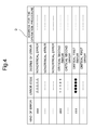
- FIG. 4 is a view showing a data table that is used for the processing procedure illustrated in FIG. 3 .
- FIG. 5 is a view showing a display unit of the image forming apparatus on which an error code and an operation procedure are displayed.
- FIG. 6 is a view showing the display unit of the image forming apparatus on which an error code for a second error is displayed.
- FIG. 7 is a view showing the display unit of the image forming apparatus on which an error code for a first error is displayed.
- FIG. 8 is a view showing the display unit of the image forming apparatus on which a maintenance screen for the second error is displayed.
- FIG. 9 is a view showing the display unit of the image forming apparatus on which the error code for the first error and a message are displayed.
- FIG. 10 is a view showing the display unit of the image forming apparatus on which a maintenance screen for the first error is displayed.
- FIG. 1 is a sectional view showing an image forming apparatus according to the embodiment of the present disclosure.
- FIG. 2 is a block diagram showing a configuration of the image forming apparatus according to the one embodiment.
- the image forming apparatus 10 is a multifunction peripheral (MFP) having a plurality of functions, such as copying, printing, scanning, and facsimile transmission.
- the image forming apparatus 10 includes units such as a control unit 11 , a display unit 12 , a plurality of sensors 13 , an operation unit 14 , a touch panel 15 , an image reading unit 17 , an image forming unit 18 , and a storage unit 19 . These components are capable of mutually transmitting and receiving data and signals through a bus.
- the image reading unit 17 includes a scanner that optically reads a document, and generates an image data indicating the image of the document to thereby store the document image on the storage unit 19 .
- the image forming unit 18 evenly charges each surface of photosensitive drums 20 and exposes the surfaces of the photosensitive drums 20 to form an electrostatic latent image thereon.
- the electrostatic latent image on the surfaces of the photosensitive drums 20 is developed into an toner image and the toner image (image) formed on the surfaces of the photosensitive drums 20 is transferred onto a recording paper sheet through an intermediate transfer belt, then the toner image is fixed on the recording paper sheet then the sheet is discharged.
- the image forming unit 18 for example, prints an image indicated by the image data formed on the image reading unit 17 onto a recording paper sheet.
- the display unit 12 is formed of a liquid crystal display (LCD) or an organic light-emitting diode (OLED) display.
- LCD liquid crystal display
- OLED organic light-emitting diode
- the display unit 12 includes a touch panel 15 on the screen thereof.
- the touch panel 15 which may be of a resistive film type or an electrostatic capacitance type, serves as the operation unit on which a user's operation performed on the screen of the display unit 12 is inputted.
- the operation unit 14 is constituted of hard keys including, for example, numeric keys and a start key.
- the storage unit 19 is a large-capacity storage device such as an HDD (Hard Disk Drive).
- HDD Hard Disk Drive
- the plurality of sensors 13 detects various causes for the interruption. For example, each of the sensors 13 detects a paper jam, a place of the paper jam, paper exhaustion, toner exhaustion, an error at the image forming unit 18 and so on as the causes for the interruption for the job using the copying function and the printing function.
- the control unit 11 includes a processor, a RAM (random access memory), and a ROM (read only memory).
- the processor is, for example, a CPU (central processing unit), an MPU (micro processing unit), or an ASIC (application specific integrated circuit).
- the control unit 11 acts as a controller 21 , an operation accepting section 22 , and a display controller 23 when the processor executes a program stored in the ROM or the storage unit 19 .
- each of the controller 21 , the operation accepting section 22 , and the display controller 23 of the control unit 11 may be constituted in the form of a hardware circuit, instead of being performed according to the program.
- the controller 21 serves to control the overall operation of the image forming apparatus 10 .
- the operation accepting section 22 has a function of accepting, based on a signal outputted from the touch panel 15 , the user's operation performed on the touch panel 15 . Additionally, the operation accepting section 22 has a function of accepting the user's operation performed on the hard key, such as the numeric key and the start key, of the operation unit 14 .
- the display controller 23 controls the display unit 12 and allows the display unit 12 to display, for example, an input screen for setting items that are necessary for image forming processing, an information input screen, and an operation procedure of the image forming apparatus 10 .
- the controller 21 of the image forming apparatus 10 in this embodiment generates log information with respect to the operation of the image forming apparatus 10 , and stores the log information on a RAM (volatile memory) of the control unit 11 .
- the log information is used, for example, to grasp an error occurrence condition.
- the controller 21 determines, based on detection output of each of the sensors 13 , the error that has occurred at the image forming apparatus 10 during operation of the image forming apparatus 10 . Based on the detection output of each of the sensors 13 , when the controller 21 determines an occurrence of a noncritical error, the controller 21 allows the display unit 12 to display, through the display controller 23 , an operation procedure for eliminating the noncritical error. The user sees the operation procedure and operates the procedure for eliminating the noncritical error.
- the controller 21 determines an occurrence of a critical error
- the controller 21 allows the display unit 12 to display, through the display controller 23 , an error code corresponding to the critical error, instead of the operation procedure.
- a service person must be called in this situation.
- the service person operates the operation unit 14 , inputs the password to activate the maintenance mode, and then performs an operation for the maintenance to eliminate the critical error.
- the controller 21 reads out the log information from the RAM, and after saving the log information onto the storage unit 19 or onto an external USB memory, allows the display unit 12 to display, through the display controller 23 , the maintenance screen, so that operation based on the maintenance screen can be performed.
- the controller 21 reads out the log information from the RAM, and after saving the log information onto the storage unit 19 or onto an external USB memory, allows the display unit 12 to display, through the display controller 23 , the maintenance screen, so that operation based on the maintenance screen can be performed.
- Such the configuration prevents the log information from being lost and avoids a situation where an error occurrence condition cannot be analyzed based on the log information.
- the controller 21 determines, based on the detection output of each of the sensors 13 , whether an error has occurred or not (step S 101 ). In determining that the error has occurred (YES in step S 101 ), the controller 21 identifies the kind of the occurred error and determines which of the noncritical error, a critical first error, and a critical second error the error that has occurred is (step S 102 ).
- the data table D stores, for every kind of error, the following items in association with each other: the error code indicating the error; the degree of the error (i.e., noncritical error, critical first error, or critical second error); and the address for the operation procedure for eliminating the respective error.
- the noncritical error is the error that can be eliminated by the user's operation.
- the critical first error is the error that is eliminated by the operation performed by the service person under the maintenance mode, and is the error in which the log information stored in the RAM of the control unit 11 might be initialized or deleted due to the operation for eliminating the critical first error.
- the critical second error is the error that is eliminated by the operation under the maintenance mode, and is the error in which there are no possibilities for the log information to be initialized or deleted due to the operation for eliminating the critical second error.
- the address for the operation procedure is the address in the storage unit 19 in which the operation procedure is stored. The operation procedure can be read out from the storage unit 19 according to the address.
- the controller 21 determines which of the noncritical error, the critical first error, and the critical second error is the error that has occurred. At the same time, by referring to the data table D, the controller 21 extracts the error code corresponding to the occurred error and obtains an address for the operation procedure for eliminating the occurred error and reads out the operation procedure from the storage unit 19 .
- the controller 21 When, for example, in determining that the occurred error is the noncritical error (“NONCRITICAL” in step S 102 ), the controller 21 , through the display controller 23 , allows the display unit 12 to display the error code corresponding to the occurred noncritical error and the operation procedure for eliminating the error (step S 103 ) illustrated in FIG. 5 . In this case, the user sees the operation procedure and operates the procedure for eliminating the error (step S 104 ).
- the controller 21 in determining that the occurred error is the critical first error or the critical second error (“CRITICAL” in step S 102 ), the controller 21 , through the display controller 23 , allows the display unit 12 to display the error code corresponding to the occurred second error, as illustrated in FIG. 6 , or to display the error code corresponding to the occurred first error, as illustrated in FIG. 7 (step S 105 ).
- the operation procedure for eliminating the error as illustrated in FIG. 5 is not to be displayed at the display unit 12 . The user can judge that it is necessary to call the service person in seeing the display illustrated in FIG. 6 and FIG. 7 .
- the service person After the service person is called, the service person sees the display illustrated in FIG. 6 and FIG. 7 , and determines that it is necessary to activate the maintenance mode. The service person then operates the operation unit 14 to input the preset password for activating the maintenance mode.
- the controller 21 compares the password with the password having been stored in the storage unit 19 for authentication (step S 106 ), and activates the maintenance mode (step S 107 ).
- the controller 21 determines which of the critical first error and the second error the occurred error is (step S 108 ). In determining that the occurred error is the critical second error (“SECOND ERROR” in step S 108 ), the controller 21 allows, through the display controller 23 , the display unit 12 to display a maintenance screen G 2 (step S 109 ) illustrated in FIG. 8 .
- the maintenance screen G 2 illustrated in FIG. 8 displays, for example, the error code corresponding to the second error and the operation procedure for eliminating the second error.
- the service person sees the maintenance screen G 2 and operates the procedure for eliminating the second error (step S 110 ).
- the second error is the error in which there are no possibilities for the log information stored in the RAM of the control unit 11 to be initialized or deleted due to the operation for eliminating the second error, so that loss of the log information will never happen.
- the controller 21 allows, through the display controller 23 , the display unit 12 to display the error code corresponding to the first error, and the message M indicating that the maintenance mode is under the activation state (step S 111 ) illustrated in FIG. 9 .
- the display unit 12 only displays the error code for the first error, and the message M indicating that the maintenance mode is under the activation state.
- the service person can recognize that the occurred error is the critical first error by seeing the display illustrated in FIG. 9 .
- the service person can also recognize that the maintenance mode is under the activation state.
- the critical first error described above is the error in which the log information stored in the RAM of the control unit 11 might be initialized or deleted due to the operation for eliminating the critical first error. Therefore, the service person operates the operation unit 14 to instruct the saving of the log information store in the RAM of the control unit 11 .
- the controller 21 reads out the log information from the RAM of the control unit 11 , and saves the log information onto predetermined recording medium such as the storage unit 19 or the external USB memory (step S 112 ).
- the controller 21 may be designed to save the log information onto the predetermined recording medium when the display unit 12 is allowed to display the error code corresponding to the first error, and the message M indicating that the maintenance mode is under the activation state, without waiting for the saving instruction.
- the controller 21 After saving the log information, the controller 21 allows, through the display controller 23 , the display unit 12 to display a maintenance screen G 1 (step S 113 ) illustrated in FIG. 10 .
- the maintenance screen G 1 illustrated in FIG. 10 displays, for example, the operation procedure for eliminating the first error.
- the service person sees the maintenance screen and operates the operation for eliminating the critical first error (step S 114 ).
- log information with respect to operation of the image forming apparatuses is stored on a memory.
- the log information is used, for example, to grasp an error occurrence condition.
- log information is deleted from a memory.
- a memory storing log information is initialized, and in other cases, the log information stored in the memory is deleted due to the elimination of an error.
- elimination of the error itself was difficult, and an error became impossible to be analyzed based on the log information.
- the aforementioned general image forming apparatuses do not refer to any techniques of preventing log information from being lost due to the above described maintenance operation.
- the controller 21 allows the display unit 12 to display the error code corresponding to the first error, and the message M indicating that the maintenance mode is under the activation state, and then the service person operates the operation unit 14 to input the password and to instruct the saving of the log information at the same time, the log information is read out from the RAM.
- the read out log information is stored in the storage unit 19 or the external USB memory to be saved.
- the controller 21 allows the display unit 12 to display the maintenance screen G 2 , enabling the operation based on the maintenance screen G 2 to be operated. Accordingly, the loss of the log information is prevented and the error occurrence condition can be surely analyzed based on the log information.
- the maintenance mode when the password inputted by operating the operation unit 14 is authenticated, the maintenance mode is activated. Therefore, the maintenance operation can be performed by operating the operation unit 14 , even when the maintenance screen G 1 is not shown on the display unit 12 . However, by not displaying the maintenance screen G 1 , it is capable of notifying the service person of the risk of losing the log information due to the maintenance operation. In this manner, the service person is urged to save the log information; thereby the loss of the log information can be prevented.
- the maintenance mode is activated, and the maintenance operation can be performed by operating the operation unit 14 .
- This embodiment follows the procedure of: inputting of the password by operating the operation unit 14 ; activating of the maintenance mode; displaying the error code corresponding to the first error, and the message M; instructing for saving the log information by operating the operation unit 14 ; saving the log information; and displaying the maintenance screen G 1 .
- the controller 21 may follow a procedure of: activating the maintenance mode along with reading out the log information from the RAM and performing the saving; and subsequently, allowing the display unit 12 to display the maintenance screen G 1 .
Landscapes
- Engineering & Computer Science (AREA)
- Multimedia (AREA)
- Signal Processing (AREA)
- Physics & Mathematics (AREA)
- General Physics & Mathematics (AREA)
- Theoretical Computer Science (AREA)
- Microelectronics & Electronic Packaging (AREA)
- Human Computer Interaction (AREA)
- General Engineering & Computer Science (AREA)
- General Health & Medical Sciences (AREA)
- Biomedical Technology (AREA)
- Health & Medical Sciences (AREA)
- Facsimiles In General (AREA)
- Control Or Security For Electrophotography (AREA)
- Accessory Devices And Overall Control Thereof (AREA)
Abstract
An image forming apparatus includes a display unit, an operation unit, a memory, and a control unit. The operation unit is operable by a user. The memory stores log information. The control unit includes a processor and, based on operation of the processor in accordance with an operation control program, allows, at an occurrence of an error, the display unit to display an error code corresponding to the error, and upon acceptance of input of a maintenance mode activation password inputted by operating the operation unit, activates a maintenance mode. Under an activation state of the maintenance mode, the control unit reads out the log information from the memory and saves the log information onto a predetermined recording medium, and allows the display unit to display a maintenance screen after the saving of the log information.
Description
This application claims priority to Japanese Patent Application No. 2016-148961 filed on Jul. 28, 2016, the entire disclosure of which are incorporated herein by reference.
The present disclosure relates to image forming apparatuses that execute a maintenance mode at an occurrence of an error and particularly relates to a technique of displaying a maintenance screen.
Some image forming apparatuses display, at an occurrence of an error, an operation procedure for eliminating the error on a display unit. A user sees the displayed operation procedure and conducts the operation for eliminating the error. When a critical error has occurred, an error code for example is displayed on the display unit instead of the operation procedure. A service person is called in such cases. The service person inputs a password to display a maintenance screen on the display unit, sees the maintenance screen, and operates the procedure for eliminating the error.
Also in some image forming apparatuses, an error message is displayed in a superimposed manner on a screen of a normal operation, so that the screen of the normal operation right before the occurrence of the error can be viewed.
Furthermore, some image forming apparatuses are capable of arbitrarily setting a presence and absence, a display time, a color, and so on of a display of the message, in accordance with kinds of the message.
A technique improved over the aforementioned techniques is proposed herein as an aspect of the present disclosure.
An image forming apparatus according to an aspect of the present disclosure includes a display unit, an operation unit, a memory, and a control unit. The operation unit is operable by a user. The memory stores log information. The control unit includes a processor, and based on operation of the processor in accordance with an operation control program, allows the display unit, at an occurrence of an error, to display an error code corresponding to the error, and upon acceptance of input of a maintenance mode activation password inputted by operating the operation unit, activates a maintenance mode. Furthermore, under an activation state of the maintenance mode, the control unit reads out the log information from the memory and saves the log information onto a predetermined recording medium, and allows the display unit to display a maintenance screen after the saving of the log information.
Hereinafter, a description will be given for one embodiment of the present disclosure with reference to the drawings.
The image forming apparatus 10 according to the one embodiment is a multifunction peripheral (MFP) having a plurality of functions, such as copying, printing, scanning, and facsimile transmission. The image forming apparatus 10 includes units such as a control unit 11, a display unit 12, a plurality of sensors 13, an operation unit 14, a touch panel 15, an image reading unit 17, an image forming unit 18, and a storage unit 19. These components are capable of mutually transmitting and receiving data and signals through a bus.
The image reading unit 17 includes a scanner that optically reads a document, and generates an image data indicating the image of the document to thereby store the document image on the storage unit 19.
The image forming unit 18 evenly charges each surface of photosensitive drums 20 and exposes the surfaces of the photosensitive drums 20 to form an electrostatic latent image thereon. The electrostatic latent image on the surfaces of the photosensitive drums 20 is developed into an toner image and the toner image (image) formed on the surfaces of the photosensitive drums 20 is transferred onto a recording paper sheet through an intermediate transfer belt, then the toner image is fixed on the recording paper sheet then the sheet is discharged. The image forming unit 18, for example, prints an image indicated by the image data formed on the image reading unit 17 onto a recording paper sheet.
The display unit 12 is formed of a liquid crystal display (LCD) or an organic light-emitting diode (OLED) display.
The display unit 12 includes a touch panel 15 on the screen thereof. The touch panel 15, which may be of a resistive film type or an electrostatic capacitance type, serves as the operation unit on which a user's operation performed on the screen of the display unit 12 is inputted.
The operation unit 14 is constituted of hard keys including, for example, numeric keys and a start key.
The storage unit 19 is a large-capacity storage device such as an HDD (Hard Disk Drive).
When a job at the image forming apparatus 10 is interrupted, the plurality of sensors 13 detects various causes for the interruption. For example, each of the sensors 13 detects a paper jam, a place of the paper jam, paper exhaustion, toner exhaustion, an error at the image forming unit 18 and so on as the causes for the interruption for the job using the copying function and the printing function.
The control unit 11 includes a processor, a RAM (random access memory), and a ROM (read only memory). The processor is, for example, a CPU (central processing unit), an MPU (micro processing unit), or an ASIC (application specific integrated circuit). The control unit 11 acts as a controller 21, an operation accepting section 22, and a display controller 23 when the processor executes a program stored in the ROM or the storage unit 19. Here, each of the controller 21, the operation accepting section 22, and the display controller 23 of the control unit 11 may be constituted in the form of a hardware circuit, instead of being performed according to the program.
The controller 21 serves to control the overall operation of the image forming apparatus 10.
The operation accepting section 22 has a function of accepting, based on a signal outputted from the touch panel 15, the user's operation performed on the touch panel 15. Additionally, the operation accepting section 22 has a function of accepting the user's operation performed on the hard key, such as the numeric key and the start key, of the operation unit 14.
The display controller 23 controls the display unit 12 and allows the display unit 12 to display, for example, an input screen for setting items that are necessary for image forming processing, an information input screen, and an operation procedure of the image forming apparatus 10.
During operation of the image forming apparatus 10, the controller 21 of the image forming apparatus 10 in this embodiment generates log information with respect to the operation of the image forming apparatus 10, and stores the log information on a RAM (volatile memory) of the control unit 11. The log information is used, for example, to grasp an error occurrence condition.
Also, the controller 21 determines, based on detection output of each of the sensors 13, the error that has occurred at the image forming apparatus 10 during operation of the image forming apparatus 10. Based on the detection output of each of the sensors 13, when the controller 21 determines an occurrence of a noncritical error, the controller 21 allows the display unit 12 to display, through the display controller 23, an operation procedure for eliminating the noncritical error. The user sees the operation procedure and operates the procedure for eliminating the noncritical error.
In addition, based on the detection output of each of the sensors 13, when the controller 21 determines an occurrence of a critical error, the controller 21 allows the display unit 12 to display, through the display controller 23, an error code corresponding to the critical error, instead of the operation procedure. A service person must be called in this situation. The service person operates the operation unit 14, inputs the password to activate the maintenance mode, and then performs an operation for the maintenance to eliminate the critical error.
In general image forming apparatuses, when operation under a maintenance mode is performed by a service person, there are occasions in which log information stored in the RAM of the control unit is initialized and the log information stored in the RAM is deleted due to elimination of the error.
In contrast, in the image forming apparatus 10 according to the embodiment of the present disclosure, when there is a possibility that the log information may be lost, the controller 21 reads out the log information from the RAM, and after saving the log information onto the storage unit 19 or onto an external USB memory, allows the display unit 12 to display, through the display controller 23, the maintenance screen, so that operation based on the maintenance screen can be performed. Such the configuration prevents the log information from being lost and avoids a situation where an error occurrence condition cannot be analyzed based on the log information.
Hereinafter, a processing procedure from the occurrence of the error up to the display of the screen to be referred to for eliminating the error will be described with reference to a flowchart illustrated in FIG. 3 .
First of all, during operation of the image forming apparatus 10, the controller 21 determines, based on the detection output of each of the sensors 13, whether an error has occurred or not (step S101). In determining that the error has occurred (YES in step S101), the controller 21 identifies the kind of the occurred error and determines which of the noncritical error, a critical first error, and a critical second error the error that has occurred is (step S102).
For example, based on a data table D illustrated in FIG. 4 , it is determined which of the noncritical error, the critical first error, and the critical second error is the occurred error. The data table D stores, for every kind of error, the following items in association with each other: the error code indicating the error; the degree of the error (i.e., noncritical error, critical first error, or critical second error); and the address for the operation procedure for eliminating the respective error. The noncritical error is the error that can be eliminated by the user's operation. The critical first error is the error that is eliminated by the operation performed by the service person under the maintenance mode, and is the error in which the log information stored in the RAM of the control unit 11 might be initialized or deleted due to the operation for eliminating the critical first error. The critical second error is the error that is eliminated by the operation under the maintenance mode, and is the error in which there are no possibilities for the log information to be initialized or deleted due to the operation for eliminating the critical second error. The address for the operation procedure is the address in the storage unit 19 in which the operation procedure is stored. The operation procedure can be read out from the storage unit 19 according to the address.
As thus far described, by referring to the data table D, the controller 21 determines which of the noncritical error, the critical first error, and the critical second error is the error that has occurred. At the same time, by referring to the data table D, the controller 21 extracts the error code corresponding to the occurred error and obtains an address for the operation procedure for eliminating the occurred error and reads out the operation procedure from the storage unit 19.
When, for example, in determining that the occurred error is the noncritical error (“NONCRITICAL” in step S102), the controller 21, through the display controller 23, allows the display unit 12 to display the error code corresponding to the occurred noncritical error and the operation procedure for eliminating the error (step S103) illustrated in FIG. 5 . In this case, the user sees the operation procedure and operates the procedure for eliminating the error (step S104).
Additionally, in determining that the occurred error is the critical first error or the critical second error (“CRITICAL” in step S102), the controller 21, through the display controller 23, allows the display unit 12 to display the error code corresponding to the occurred second error, as illustrated in FIG. 6 , or to display the error code corresponding to the occurred first error, as illustrated in FIG. 7 (step S105). The operation procedure for eliminating the error as illustrated in FIG. 5 , however, is not to be displayed at the display unit 12. The user can judge that it is necessary to call the service person in seeing the display illustrated in FIG. 6 and FIG. 7 .
After the service person is called, the service person sees the display illustrated in FIG. 6 and FIG. 7 , and determines that it is necessary to activate the maintenance mode. The service person then operates the operation unit 14 to input the preset password for activating the maintenance mode. When the password is accepted at the operation accepting section 22, the controller 21 compares the password with the password having been stored in the storage unit 19 for authentication (step S106), and activates the maintenance mode (step S107).
Subsequently, the controller 21 determines which of the critical first error and the second error the occurred error is (step S108). In determining that the occurred error is the critical second error (“SECOND ERROR” in step S108), the controller 21 allows, through the display controller 23, the display unit 12 to display a maintenance screen G2 (step S109) illustrated in FIG. 8 . The maintenance screen G2 illustrated in FIG. 8 displays, for example, the error code corresponding to the second error and the operation procedure for eliminating the second error. The service person sees the maintenance screen G2 and operates the procedure for eliminating the second error (step S110). As described above, the second error is the error in which there are no possibilities for the log information stored in the RAM of the control unit 11 to be initialized or deleted due to the operation for eliminating the second error, so that loss of the log information will never happen.
Furthermore, in determining that the occurred error is the critical first error (“FIRST ERROR” in step S108), the controller 21 allows, through the display controller 23, the display unit 12 to display the error code corresponding to the first error, and the message M indicating that the maintenance mode is under the activation state (step S111) illustrated in FIG. 9 . Thus, in a case where the occurred error is the critical first error, even when the password inputted by operating the operation unit 14 is authenticated and the maintenance mode is activated, the maintenance screen is not displayed at the display unit 12 immediately. As illustrated in FIG. 9 , the display unit 12 only displays the error code for the first error, and the message M indicating that the maintenance mode is under the activation state.
In this case, the service person can recognize that the occurred error is the critical first error by seeing the display illustrated in FIG. 9 . The service person can also recognize that the maintenance mode is under the activation state. The critical first error described above is the error in which the log information stored in the RAM of the control unit 11 might be initialized or deleted due to the operation for eliminating the critical first error. Therefore, the service person operates the operation unit 14 to instruct the saving of the log information store in the RAM of the control unit 11. When the instruction is accepted at the operation accepting section 22, the controller 21 reads out the log information from the RAM of the control unit 11, and saves the log information onto predetermined recording medium such as the storage unit 19 or the external USB memory (step S112). The controller 21 may be designed to save the log information onto the predetermined recording medium when the display unit 12 is allowed to display the error code corresponding to the first error, and the message M indicating that the maintenance mode is under the activation state, without waiting for the saving instruction.
After saving the log information, the controller 21 allows, through the display controller 23, the display unit 12 to display a maintenance screen G1 (step S113) illustrated in FIG. 10 . The maintenance screen G1 illustrated in FIG. 10 displays, for example, the operation procedure for eliminating the first error. The service person sees the maintenance screen and operates the operation for eliminating the critical first error (step S114).
In contrast, during operation of general image forming apparatuses, log information with respect to operation of the image forming apparatuses is stored on a memory. The log information is used, for example, to grasp an error occurrence condition.
However, in some cases of general image forming apparatuses, as described above, when a critical error has occurred and an operation for the maintenance is performed by a service person, log information is deleted from a memory. For example, in some cases, when operation for the maintenance is performed, a memory storing log information is initialized, and in other cases, the log information stored in the memory is deleted due to the elimination of an error. As a result, elimination of the error itself was difficult, and an error became impossible to be analyzed based on the log information.
The aforementioned general image forming apparatuses do not refer to any techniques of preventing log information from being lost due to the above described maintenance operation.
In contrast, when the critical first error is occurred in this embodiment, the controller 21 allows the display unit 12 to display the error code corresponding to the first error, and the message M indicating that the maintenance mode is under the activation state, and then the service person operates the operation unit 14 to input the password and to instruct the saving of the log information at the same time, the log information is read out from the RAM. The read out log information is stored in the storage unit 19 or the external USB memory to be saved. Subsequently, the controller 21 allows the display unit 12 to display the maintenance screen G2, enabling the operation based on the maintenance screen G2 to be operated. Accordingly, the loss of the log information is prevented and the error occurrence condition can be surely analyzed based on the log information.
In this embodiment, when the password inputted by operating the operation unit 14 is authenticated, the maintenance mode is activated. Therefore, the maintenance operation can be performed by operating the operation unit 14, even when the maintenance screen G1 is not shown on the display unit 12. However, by not displaying the maintenance screen G1, it is capable of notifying the service person of the risk of losing the log information due to the maintenance operation. In this manner, the service person is urged to save the log information; thereby the loss of the log information can be prevented.
In addition, even in a case where the occurrence of the critical first error or the critical second error damages the display unit 12 itself, when the password inputted by operating the operation unit 14 is authenticated, the maintenance mode is activated, and the maintenance operation can be performed by operating the operation unit 14.
This embodiment follows the procedure of: inputting of the password by operating the operation unit 14; activating of the maintenance mode; displaying the error code corresponding to the first error, and the message M; instructing for saving the log information by operating the operation unit 14; saving the log information; and displaying the maintenance screen G1. However, when the password is inputted by operating the operation unit 14, the controller 21 may follow a procedure of: activating the maintenance mode along with reading out the log information from the RAM and performing the saving; and subsequently, allowing the display unit 12 to display the maintenance screen G1.
Further, the configurations and processes of the embodiment described with reference to FIGS. 1 to 10 are merely exemplary, and not intended to limit the scope of the disclosure.
Various modifications and alterations of this disclosure will be apparent to those skilled in the art without departing from the scope and spirit of this disclosure, and it should be understood that this disclosure is not limited to the illustrative embodiments set forth herein.
Claims (2)
1. An image forming apparatus comprising:
a display unit;
an operation unit operable by a user;
a memory that stores log information; and
a control unit that includes a processor, and based on operation of the processor in accordance with an operation control program, allows the display unit, at an occurrence of an error, to display an error code corresponding to the error, and upon acceptance of input of a maintenance mode activation password inputted by operating the operation unit, activates a maintenance mode,
wherein under an activation state of the maintenance mode, the control unit reads out the log information from the memory and saves the log information onto a predetermined recording medium, and allows the display unit to display a maintenance screen after the saving of the log information,
furthermore, the control unit preliminarily stores an error code for a first error that requires the saving of the log information from the memory, and an error code for a second error that does not require the saving of the log information from the memory,
in a case of allowing the display unit to display the error code for the first error at an occurrence of the first error, under the activation state of the maintenance mode, the control unit reads out the log information from the memory and saves the log information, and allows the display unit to display the maintenance screen after the saving of the log information, and
in a case of allowing the display unit to display the error code for the second error at an occurrence of the second error, under the activation state of the maintenance mode, the control unit allows the display unit to display the maintenance screen without reading out the log information from the memory and saving the log information.
2. The image forming apparatus according to claim 1 , wherein in the case where the control unit has allowed the display unit to display the error code for the first error, the control unit allows the display unit to display a message indicating that the maintenance mode is under the activation state, along with the error code for the first error.
Applications Claiming Priority (2)
| Application Number | Priority Date | Filing Date | Title |
|---|---|---|---|
| JP2016-148961 | 2016-07-28 | ||
| JP2016148961A JP6458783B2 (en) | 2016-07-28 | 2016-07-28 | Image forming apparatus |
Publications (2)
| Publication Number | Publication Date |
|---|---|
| US20180032020A1 US20180032020A1 (en) | 2018-02-01 |
| US10061257B2 true US10061257B2 (en) | 2018-08-28 |
Family
ID=61012287
Family Applications (1)
| Application Number | Title | Priority Date | Filing Date |
|---|---|---|---|
| US15/647,606 Active US10061257B2 (en) | 2016-07-28 | 2017-07-12 | Image forming apparatus |
Country Status (3)
| Country | Link |
|---|---|
| US (1) | US10061257B2 (en) |
| JP (1) | JP6458783B2 (en) |
| CN (1) | CN107666551B (en) |
Families Citing this family (7)
| Publication number | Priority date | Publication date | Assignee | Title |
|---|---|---|---|---|
| JP7039377B2 (en) * | 2018-04-18 | 2022-03-22 | キヤノン株式会社 | Information processing device, control method of information processing device, and program |
| JP7234718B2 (en) * | 2019-03-18 | 2023-03-08 | 富士フイルムビジネスイノベーション株式会社 | Information processing device, information processing system and program |
| JP7470572B2 (en) * | 2020-06-03 | 2024-04-18 | シャープ株式会社 | Information processing device |
| JP7718808B2 (en) * | 2020-11-11 | 2025-08-05 | 東芝テック株式会社 | Server device and its control program |
| CN114290828B (en) * | 2021-12-31 | 2024-05-03 | 珠海奔图电子有限公司 | Control method and device of image forming device |
| JP2023131943A (en) * | 2022-03-10 | 2023-09-22 | セイコーエプソン株式会社 | Image forming device, jig to be used in operating image forming device, and electronic instrument |
| JP2024000269A (en) * | 2022-06-20 | 2024-01-05 | シャープ株式会社 | Information processing equipment and explanation information processing system |
Citations (5)
| Publication number | Priority date | Publication date | Assignee | Title |
|---|---|---|---|---|
| US6470413B1 (en) * | 1996-07-19 | 2002-10-22 | Canon Kabushiki Kaisha | Information processing apparatus and method in which an executable file in an incorporated memory is loaded and executed at startup |
| JP2005334454A (en) | 2004-05-28 | 2005-12-08 | Ace Denken:Kk | Game media counter |
| US20080079659A1 (en) | 2006-10-03 | 2008-04-03 | Sharp Kabushiki Kaisha | Image processing apparatus |
| US8976390B2 (en) * | 2012-02-17 | 2015-03-10 | Canon Kabushiki Kaisha | Image processing apparatus having storage unit that stores setting values, and control method and storage medium therefor |
| US20150212468A1 (en) * | 2014-01-27 | 2015-07-30 | Canon Kabushiki Kaisha | Image forming apparatus capable of limiting range of operation during maintenance, control method therefor, and storage medium |
Family Cites Families (8)
| Publication number | Priority date | Publication date | Assignee | Title |
|---|---|---|---|---|
| JPH11215232A (en) * | 1998-01-28 | 1999-08-06 | Oki Electric Ind Co Ltd | Remote maintenance system for exchange |
| JP4273724B2 (en) * | 2002-08-29 | 2009-06-03 | カシオ電子工業株式会社 | Consumables unauthorized use prevention system |
| JP4522165B2 (en) * | 2004-06-29 | 2010-08-11 | 株式会社サトー | Printer with memory card and its operation history saving method |
| JP2006256056A (en) * | 2005-03-16 | 2006-09-28 | Ricoh Co Ltd | Image forming apparatus |
| JP4440294B2 (en) * | 2007-10-16 | 2010-03-24 | シャープ株式会社 | Image processing system and image forming apparatus |
| JP2010061579A (en) * | 2008-09-05 | 2010-03-18 | Riso Kagaku Corp | Information processing apparatus |
| EP2172890A1 (en) * | 2008-09-26 | 2010-04-07 | Brother Kogyo Kabushiki Kaisha | Image forming device and management device and management system for image forming |
| JP2014087129A (en) * | 2012-10-22 | 2014-05-12 | Sharp Corp | Power supply system |
-
2016
- 2016-07-28 JP JP2016148961A patent/JP6458783B2/en not_active Expired - Fee Related
-
2017
- 2017-07-12 US US15/647,606 patent/US10061257B2/en active Active
- 2017-07-25 CN CN201710613032.2A patent/CN107666551B/en not_active Expired - Fee Related
Patent Citations (7)
| Publication number | Priority date | Publication date | Assignee | Title |
|---|---|---|---|---|
| US6470413B1 (en) * | 1996-07-19 | 2002-10-22 | Canon Kabushiki Kaisha | Information processing apparatus and method in which an executable file in an incorporated memory is loaded and executed at startup |
| JP2005334454A (en) | 2004-05-28 | 2005-12-08 | Ace Denken:Kk | Game media counter |
| US20080079659A1 (en) | 2006-10-03 | 2008-04-03 | Sharp Kabushiki Kaisha | Image processing apparatus |
| JP2008092368A (en) | 2006-10-03 | 2008-04-17 | Sharp Corp | Image processing device |
| US8136049B2 (en) | 2006-10-03 | 2012-03-13 | Sharp Kabushiki Kaisha | Image processing apparatus |
| US8976390B2 (en) * | 2012-02-17 | 2015-03-10 | Canon Kabushiki Kaisha | Image processing apparatus having storage unit that stores setting values, and control method and storage medium therefor |
| US20150212468A1 (en) * | 2014-01-27 | 2015-07-30 | Canon Kabushiki Kaisha | Image forming apparatus capable of limiting range of operation during maintenance, control method therefor, and storage medium |
Also Published As
| Publication number | Publication date |
|---|---|
| JP2018019289A (en) | 2018-02-01 |
| CN107666551B (en) | 2019-10-25 |
| JP6458783B2 (en) | 2019-01-30 |
| CN107666551A (en) | 2018-02-06 |
| US20180032020A1 (en) | 2018-02-01 |
Similar Documents
| Publication | Publication Date | Title |
|---|---|---|
| US10061257B2 (en) | Image forming apparatus | |
| US9471266B2 (en) | Printing system with printing apparatus and printing control apparatus for registering and managing sheet holding units based on sheet attributes | |
| US10574854B2 (en) | Imaging processing apparatus for receiving print data from server and performing image processing and method for controlling the same | |
| KR20140017654A (en) | Information processing apparatus that offers chance of eliminating hang-up state, control method therefor, and storage medium | |
| US20140368854A1 (en) | Image forming apparatus, control method for image forming apparatus, and storage medium | |
| JP6489314B2 (en) | Image forming apparatus | |
| US10162579B2 (en) | Image forming apparatus and control method for setting and holding print settings | |
| US20130301074A1 (en) | Image processing apparatus | |
| US10579014B2 (en) | Image forming apparatus for removing dew condensation, control method for image forming apparatus, and storage medium | |
| US10795621B2 (en) | Image forming apparatus detects human body to lift suspension on printing process for executing a print job | |
| US9924059B2 (en) | Apparatus having power-saving function, method of processing information, and computer program product | |
| US11115543B2 (en) | Image processing apparatus, and control method and storage medium thereof | |
| US8934105B2 (en) | Image forming apparatus and control method with error detecting and line switching function | |
| US11039032B2 (en) | Printing apparatus executable of condensation removal processing, method of controlling printing apparatus, and storage medium | |
| US10715696B2 (en) | Information processing system including image forming apparatus that transmits image data to information processing apparatus and information processing apparatus that determines storage area to store image data, information processing apparatus that determines storage area to store image data, and image forming apparatus that transmits image data to information processing apparatus | |
| US20160224948A1 (en) | Maintenance management device and maintenance management method | |
| US12531954B2 (en) | Information processing apparatus, non-transitory computer readable medium storing program, and information processing method for notifying unauthorized operations | |
| US10509507B2 (en) | Display device, information processing apparatus, method for controlling display device, and storage medium | |
| US20230004334A1 (en) | Image forming apparatus that performs inspection processing on print data and method of controlling image forming apparatus | |
| US11949824B2 (en) | Image forming apparatus and method for notifying detection of virus | |
| US11700340B2 (en) | Method for registering a terminal in an image forming apparatus | |
| JP2021072518A (en) | Image forming apparatus | |
| JP2007007980A (en) | Image forming apparatus and method for controlling the same | |
| US9992377B2 (en) | Information processing apparatus for authenticating user, information processing method | |
| JP2006347080A (en) | Image forming device, control method of image forming device, and control program of image forming device |
Legal Events
| Date | Code | Title | Description |
|---|---|---|---|
| AS | Assignment |
Owner name: KYOCERA DOCUMENT SOLUTIONS INC., JAPAN Free format text: ASSIGNMENT OF ASSIGNORS INTEREST;ASSIGNOR:SHINTANI, YOSHIHISA;REEL/FRAME:042986/0558 Effective date: 20170621 |
|
| STCF | Information on status: patent grant |
Free format text: PATENTED CASE |
|
| MAFP | Maintenance fee payment |
Free format text: PAYMENT OF MAINTENANCE FEE, 4TH YEAR, LARGE ENTITY (ORIGINAL EVENT CODE: M1551); ENTITY STATUS OF PATENT OWNER: LARGE ENTITY Year of fee payment: 4 |