US10049610B2 - Display apparatus and method for controlling same - Google Patents
Display apparatus and method for controlling same Download PDFInfo
- Publication number
- US10049610B2 US10049610B2 US14/943,501 US201514943501A US10049610B2 US 10049610 B2 US10049610 B2 US 10049610B2 US 201514943501 A US201514943501 A US 201514943501A US 10049610 B2 US10049610 B2 US 10049610B2
- Authority
- US
- United States
- Prior art keywords
- divided regions
- regions
- image
- light sources
- brightness
- Prior art date
- Legal status (The legal status is an assumption and is not a legal conclusion. Google has not performed a legal analysis and makes no representation as to the accuracy of the status listed.)
- Active, expires
Links
Images


Classifications
-
- G—PHYSICS
- G09—EDUCATION; CRYPTOGRAPHY; DISPLAY; ADVERTISING; SEALS
- G09G—ARRANGEMENTS OR CIRCUITS FOR CONTROL OF INDICATING DEVICES USING STATIC MEANS TO PRESENT VARIABLE INFORMATION
- G09G3/00—Control arrangements or circuits, of interest only in connection with visual indicators other than cathode-ray tubes
- G09G3/20—Control arrangements or circuits, of interest only in connection with visual indicators other than cathode-ray tubes for presentation of an assembly of a number of characters, e.g. a page, by composing the assembly by combination of individual elements arranged in a matrix no fixed position being assigned to or needed to be assigned to the individual characters or partial characters
- G09G3/2092—Details of a display terminals using a flat panel, the details relating to the control arrangement of the display terminal and to the interfaces thereto
-
- G—PHYSICS
- G09—EDUCATION; CRYPTOGRAPHY; DISPLAY; ADVERTISING; SEALS
- G09G—ARRANGEMENTS OR CIRCUITS FOR CONTROL OF INDICATING DEVICES USING STATIC MEANS TO PRESENT VARIABLE INFORMATION
- G09G3/00—Control arrangements or circuits, of interest only in connection with visual indicators other than cathode-ray tubes
- G09G3/20—Control arrangements or circuits, of interest only in connection with visual indicators other than cathode-ray tubes for presentation of an assembly of a number of characters, e.g. a page, by composing the assembly by combination of individual elements arranged in a matrix no fixed position being assigned to or needed to be assigned to the individual characters or partial characters
- G09G3/34—Control arrangements or circuits, of interest only in connection with visual indicators other than cathode-ray tubes for presentation of an assembly of a number of characters, e.g. a page, by composing the assembly by combination of individual elements arranged in a matrix no fixed position being assigned to or needed to be assigned to the individual characters or partial characters by control of light from an independent source
- G09G3/3406—Control of illumination source
- G09G3/342—Control of illumination source using several illumination sources separately controlled corresponding to different display panel areas, e.g. along one dimension such as lines
- G09G3/3426—Control of illumination source using several illumination sources separately controlled corresponding to different display panel areas, e.g. along one dimension such as lines the different display panel areas being distributed in two dimensions, e.g. matrix
-
- G—PHYSICS
- G09—EDUCATION; CRYPTOGRAPHY; DISPLAY; ADVERTISING; SEALS
- G09G—ARRANGEMENTS OR CIRCUITS FOR CONTROL OF INDICATING DEVICES USING STATIC MEANS TO PRESENT VARIABLE INFORMATION
- G09G3/00—Control arrangements or circuits, of interest only in connection with visual indicators other than cathode-ray tubes
- G09G3/20—Control arrangements or circuits, of interest only in connection with visual indicators other than cathode-ray tubes for presentation of an assembly of a number of characters, e.g. a page, by composing the assembly by combination of individual elements arranged in a matrix no fixed position being assigned to or needed to be assigned to the individual characters or partial characters
- G09G3/34—Control arrangements or circuits, of interest only in connection with visual indicators other than cathode-ray tubes for presentation of an assembly of a number of characters, e.g. a page, by composing the assembly by combination of individual elements arranged in a matrix no fixed position being assigned to or needed to be assigned to the individual characters or partial characters by control of light from an independent source
- G09G3/36—Control arrangements or circuits, of interest only in connection with visual indicators other than cathode-ray tubes for presentation of an assembly of a number of characters, e.g. a page, by composing the assembly by combination of individual elements arranged in a matrix no fixed position being assigned to or needed to be assigned to the individual characters or partial characters by control of light from an independent source using liquid crystals
- G09G3/3611—Control of matrices with row and column drivers
- G09G3/3648—Control of matrices with row and column drivers using an active matrix
-
- G—PHYSICS
- G09—EDUCATION; CRYPTOGRAPHY; DISPLAY; ADVERTISING; SEALS
- G09G—ARRANGEMENTS OR CIRCUITS FOR CONTROL OF INDICATING DEVICES USING STATIC MEANS TO PRESENT VARIABLE INFORMATION
- G09G2320/00—Control of display operating conditions
- G09G2320/02—Improving the quality of display appearance
- G09G2320/0233—Improving the luminance or brightness uniformity across the screen
-
- G—PHYSICS
- G09—EDUCATION; CRYPTOGRAPHY; DISPLAY; ADVERTISING; SEALS
- G09G—ARRANGEMENTS OR CIRCUITS FOR CONTROL OF INDICATING DEVICES USING STATIC MEANS TO PRESENT VARIABLE INFORMATION
- G09G2320/00—Control of display operating conditions
- G09G2320/06—Adjustment of display parameters
- G09G2320/0613—The adjustment depending on the type of the information to be displayed
- G09G2320/062—Adjustment of illumination source parameters
-
- G—PHYSICS
- G09—EDUCATION; CRYPTOGRAPHY; DISPLAY; ADVERTISING; SEALS
- G09G—ARRANGEMENTS OR CIRCUITS FOR CONTROL OF INDICATING DEVICES USING STATIC MEANS TO PRESENT VARIABLE INFORMATION
- G09G2320/00—Control of display operating conditions
- G09G2320/06—Adjustment of display parameters
- G09G2320/0626—Adjustment of display parameters for control of overall brightness
- G09G2320/0646—Modulation of illumination source brightness and image signal correlated to each other
-
- G—PHYSICS
- G09—EDUCATION; CRYPTOGRAPHY; DISPLAY; ADVERTISING; SEALS
- G09G—ARRANGEMENTS OR CIRCUITS FOR CONTROL OF INDICATING DEVICES USING STATIC MEANS TO PRESENT VARIABLE INFORMATION
- G09G2320/00—Control of display operating conditions
- G09G2320/06—Adjustment of display parameters
- G09G2320/066—Adjustment of display parameters for control of contrast
-
- G—PHYSICS
- G09—EDUCATION; CRYPTOGRAPHY; DISPLAY; ADVERTISING; SEALS
- G09G—ARRANGEMENTS OR CIRCUITS FOR CONTROL OF INDICATING DEVICES USING STATIC MEANS TO PRESENT VARIABLE INFORMATION
- G09G2320/00—Control of display operating conditions
- G09G2320/06—Adjustment of display parameters
- G09G2320/0686—Adjustment of display parameters with two or more screen areas displaying information with different brightness or colours
-
- G—PHYSICS
- G09—EDUCATION; CRYPTOGRAPHY; DISPLAY; ADVERTISING; SEALS
- G09G—ARRANGEMENTS OR CIRCUITS FOR CONTROL OF INDICATING DEVICES USING STATIC MEANS TO PRESENT VARIABLE INFORMATION
- G09G2340/00—Aspects of display data processing
- G09G2340/14—Solving problems related to the presentation of information to be displayed
-
- G—PHYSICS
- G09—EDUCATION; CRYPTOGRAPHY; DISPLAY; ADVERTISING; SEALS
- G09G—ARRANGEMENTS OR CIRCUITS FOR CONTROL OF INDICATING DEVICES USING STATIC MEANS TO PRESENT VARIABLE INFORMATION
- G09G2360/00—Aspects of the architecture of display systems
- G09G2360/16—Calculation or use of calculated indices related to luminance levels in display data
-
- G—PHYSICS
- G09—EDUCATION; CRYPTOGRAPHY; DISPLAY; ADVERTISING; SEALS
- G09G—ARRANGEMENTS OR CIRCUITS FOR CONTROL OF INDICATING DEVICES USING STATIC MEANS TO PRESENT VARIABLE INFORMATION
- G09G2380/00—Specific applications
- G09G2380/08—Biomedical applications
Definitions
- the present invention relates to a display apparatus and a method for controlling the same.
- the backlight is constituted by a plurality of light sources whose brightness is capable of being separately controlled.
- Such display apparatuses may improve display contrast by controlling the brightness of respective light sources according to input images and correcting the input images according to the brightness of the respective light sources (see, for example, Japanese Patent Application Laid-open No. 2008-51905). This technology is called local dimming.
- image correction may cause degradation in original input images due to influence by, for example, quantization error or the like.
- Liquid crystal displays have also been used for interpretation with X-ray or mammography. In such medical image observation, it is required to faithfully display original input images for accurate diagnosis. However, if display images are degraded due to image processing, the faithful display of the images is not allowed.
- the present invention performs appropriate brightness control according to types of images to prevent observers from having the feelings of interference in a display apparatus capable of separately controlling the brightness of the light sources of a backlight according to the images.
- a display apparatus including:
- a light emitting unit having a plurality of light sources and separately adjusting brightness of the respective light sources
- an acquiring unit configured to acquire a feature value of an input image for divided regions respectively corresponding to the plurality of light sources
- control unit configured to make, in a case where the input image is a first image including a predetermined object image, brightness of light sources corresponding to divided regions determined to be dark regions based on the feature values of the respective divided regions lower than brightness of light sources corresponding to other divided regions, wherein
- control unit does not implement control operation of making the brightness of the light sources corresponding to the divided regions determined to be the dark regions lower than the brightness of the light sources corresponding to the other divided regions.
- a method for controlling a display apparatus having a display panel and a light emitting unit having a plurality of light sources and separately adjusting brightness of the respective light sources comprising:
- the control operation of making the brightness of the light sources corresponding to the divided regions determined to be the dark regions lower than the brightness of the light sources corresponding to the other divided regions is not implemented.
- a display apparatus including:
- a light emitting unit having a plurality of light sources and separately adjusting brightness of the respective light sources
- an acquiring unit configured to acquire feature values of an input image for divided regions respectively corresponding to the plurality of light sources
- control unit configured to make, within a region displaying a first image including a predetermined object image in the input image, brightness of light sources corresponding to divided regions determined to be dark regions based on the feature values of the respective divided regions lower than brightness of light sources corresponding to other divided regions, wherein
- control unit does not implement control operation of making the brightness of the light sources corresponding to the divided regions determined to be the dark regions lower than the brightness of the light sources corresponding to the other divided regions.
- a method for controlling a display apparatus having a display panel and a light emitting unit having a plurality of light sources and separately adjusting brightness of the respective light sources comprising:
- the control operation of making the brightness of the light sources corresponding to the divided regions determined to be the dark regions lower than the brightness of the light sources corresponding to the other divided regions is not implemented.
- the present invention it is possible to perform appropriate brightness control according to types of images to prevent observers from having the feelings of interference in a display apparatus capable of separately controlling the brightness of the light sources of a backlight according to the images.
- FIG. 1 shows a function block diagram of a display apparatus according to a first embodiment
- FIGS. 2A to 2D show an example of a medical image and examples of the feature values thereof
- FIG. 3 shows a function block diagram of a medical image detection unit according to the first embodiment
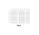
- FIG. 4 shows an example of attribute determination results according to the first embodiment
- FIGS. 5A to 5E show an example of an image other than a medical image and examples of the feature values thereof;
- FIGS. 6A to 6C show an example of histograms according to the first embodiment.
- FIG. 7 is a function block diagram of the display according to a modified example of the first embodiment.
- the display apparatus of a first embodiment divides an input image into a plurality of regions, detects the feature values of the respective divided regions of the image, and determines whether the input image is an image (first image) including a predetermined object image from the detected feature values.
- An object is, for example, an image of an object taken by radiation or ultrasonic waves, and an image including the object is, for example, a medical image for interpretation (interpretation image) such as an X-ray image.
- the display apparatus determines whether the respective divided regions are object regions in which a predetermined object image (object to be interpreted) exists or background regions indicating the background of the predetermined object image.
- the display apparatus determines the brightness of a plurality of light sources constituting a backlight according to determination results.
- the display apparatus reduces the floating of dark parts in the background regions that are not to be observed in the medical image and reduces the feelings of interference when an observer (interpretation operator or the like) interprets the medical image displayed on the display apparatus.
- FIG. 1 shows a function block diagram of a display apparatus according to a first embodiment.
- the display apparatus includes a liquid crystal panel section 1 , a backlight module section 2 , a feature value detection section 3 , a medical image detection section 4 , an attribute determination section 5 , a control section 6 , and a backlight brightness value determination section 7 .
- the liquid crystal panel section 1 includes a liquid crystal driver, a control substrate that controls the liquid crystal driver according to an input image signal, and a liquid crystal panel. Note that although the first embodiment describes an example using the liquid crystal panel as the display panel of the present invention, the display panel is not limited to the liquid crystal panel.
- the backlight module section 2 includes light sources, a control circuit that controls the light sources, and an optical unit that diffuses light from the light sources.
- the backlight module section 2 has the plurality of light sources and is capable of separately adjusting the light emission brightness of the respective light sources.
- the backlight module section 2 is divided into a plurality of blocks corresponding to the respective light sources whose brightness is capable of being separately controlled, and the brightness of the respective blocks is determined by the backlight brightness value determination section 7 .
- the control circuit of the backlight module section 2 controls the light emission of the respective light sources such that the respective light sources light up with the brightness determined by the backlight brightness value determination section 7 .
- a block-based division number is m (width) ⁇ n (length) (where m and n are integers).
- the backlight module section 2 is divided into 10 (width) ⁇ 7 (length) blocks.
- the number of the divided blocks of the backlight module section 2 may include but not limited to the above number.
- the feature value detection section 3 divides the input image into regions (divided regions) corresponding to the respective blocks of the backlight module section 2 and detects the feature values of the respective divided regions.
- the feature value detection section 3 sends the detected feature values to the medical image detection section 4 and the attribute determination section 5 on the following stage.
- the feature value detection section 3 detects, as the feature values of the respective divided regions, maximum values, average values, and bright area values of the gradation values (RGB values) of pixels constituting the divided regions.
- the bright area values are values obtained by counting the number of pixels having a gradation value of a preset threshold (sixth threshold) or more among the pixels constituting the divided regions without RGB discrimination.
- the input image has gradation values of 0 to 4095, and pixels having a gradation value of 60 or more are counted as bright pixels. That is, the sixth threshold is set at 60.
- FIGS. 2A to 2D show an example of the input image, and FIGS. 2B, 2C, and 2D show the maximum values, the average values, and the bright area values of the gradation values of the respective divided regions of the input image of FIG. 2A detected by the feature value detection section 3 .
- the numbers 1 to 10 in a horizontal direction and the numbers 1 to 7 in a vertical direction show the coordinates of the divided regions in the horizontal and vertical directions.
- the input image of FIG. 2A has, in its upper region, a menu bar that serves as a graphical user interface (GUI) to constitute a viewer to display a medical image.
- the menu bar is constituted by a graphic uniform in the horizontal direction.
- an object 200 is an image of an object taken by an X-ray or the like.
- the divided region at the coordinates (4,4) in which the object 200 exists has a maximum value of 2560, an average value of 2000, and a bright area value of 1200 as the gradation values.
- the divided region at the coordinates (4,1) in which the menu bar exists has a maximum value of 1536 and an average value of 1536 as the gradation values since the graphic is uniform, and has a bright area value of 1200.
- the feature value detection section 3 sends the acquired maximum values and the average values to the medical image detection section 4 and sends the acquired bright area values to the attribute determination section 5 .
- the medical image detection section 4 determines whether the input image is a first image including the predetermined object image or a second image not including the predetermined object image.
- the first image is a medical image taken by an X-ray.
- the second image is an image of an operating system (OS) output from, for example, a personal computer (PC).
- the medical image detection section 4 determines whether the respective divided regions are flat regions or dark flat regions.
- the flat regions are regions including only pixels in which a type of gradation values are a first threshold or less (for example, 2 or less) and that have intermediate gradation.
- the dark flat regions are regions including only pixels in which a type of gradation values is a fourth threshold or less (for example, 2 or less) and that have dark gradation.
- the pixels having the dark gradation are pixels in which a size of gradation values is a third threshold or less (for example, 64 or less).
- the medical image detection section 4 counts the determination results of the respective divided regions.
- the medical image detection section 4 compares the number of the divided regions determined to be the flat regions with a second threshold (CNth) and compares the number of the divided regions determined to be the dark flat regions with a fifth threshold (BCNth).
- CNth second threshold
- BCNth fifth threshold
- the medical image detection section 4 determines that the input image is the second image (the image of the OS) when at least any of the condition under which the number of the divided regions determined to be the flat regions is the second threshold or more and the condition under which the number of the divided regions determined to be the dark flat regions is the fifth threshold or more is satisfied. Since the input image is not a multi-gradation image when any of these conditions is satisfied, the medical image detection section 4 determines that the input image is not the first image (the medical image). Hereinafter, the determination method will be described in detail.
- a medical image including an image of an object taken by an X-ray or the like is constituted by multi-gradation (three or more gradation levels), and thus the number of types of gradation values is not reduced to 1 or 2.
- an image of an OS shown in FIG. 5A particularly a text display region and a region in which a graphic image of a GUI is displayed have only a few types of gradation values to constitute the image.
- an object 201 shows the text display region. Since the input image shown in FIG. 5A has only a few divided regions constituted by multi-gradation, a large number of flat regions are counted.
- the medical image detection section 4 determines the number of the flat regions separately from the number of the dark flat regions.
- the fifth threshold (BCNth) used to determine the number of dark flat regions is set to be larger than the second threshold (CNth) used to determine the number of flat regions having intermediate gradation.
- FIG. 3 shows a function block diagram of the medical image detection section 4 .
- the medical image detection section 4 has a dark flat region determination section 31 , a flat region determination section 32 , a dark flat region count section 33 , a flat region count section 34 , and a medical image determination section 35 .
- the respective functions will be described below.
- the dark flat region determination section 31 determines whether the respective divided regions are the dark flat regions from the maximum values and the average values of the gradation values of the respective divided regions sent from the feature value detection section 3 .
- the dark flat region determination section 31 determines that the divided regions satisfying the following formulae 1 and 2 at the same time are the dark flat regions.
- dL1 fourth threshold
- Pa1 and Pa2 third thresholds
- the dark gradation is stipulated by Pa1 and Pa2.
- the dark gradation is up to 64.
- dL1 indicates the thresholds of the sizes of the differences between the maximum values and the average values used to determine the dark flat regions. When the divided regions are constituted by the pixels of one gradation value, the sizes of the differences between the maximum values and the average values are 0. However, when noise is caused in the image, the maximum values and the average values are not equal to each other.
- the fourth threshold dL1 is set at 2 such that the divided regions having nearly uniform gradation values may be determined to be the dark flat regions even if small noise is caused.
- the divided region at the coordinates (2,2) has a maximum value of 0 and an average value of 0 and establishes the following relationships.
- the dark flat region determination section 31 determines that the divided region is the dark flat region.
- the divided region at the coordinates (1,1) has a maximum value of 1536 and an average value of 1536 and establishes the following relationships.
- the dark flat region determination section 31 does not determine that the divided region is the dark flat region.
- the dark flat region determination section 31 determines whether the respective divided regions are the dark flat regions. Then, the dark flat region determination section 31 sets the dark flat region flags of the divided regions determined to be the dark flat regions at 1 and sends the flags to the dark flat region count section 33 on the following stage. While, the dark flat region determination section 31 sets the dark flat region flags of the divided regions not determined to be the dark flat regions at 0 and sends the flags to the dark flat region count section 33 on the following stage.
- the flat region determination section 32 determines whether the respective divided regions are the intermediate gradation flat regions from the maximum values and the average values of the gradation values of the respective divided regions sent from the feature value detection section 3 .
- the flat region determination section 32 determines that the divided regions satisfying the following formulae 3 and 4 at the same time are the flat regions.
- dL2 (first threshold), Pa3, and Pa4 indicate preset thresholds.
- dL2 is set at 2
- Pa3 is set at 65
- Pa4 is set at 1600.
- the intermediate gradation is stipulated by Pa3 and Pa4.
- dL2 indicates the thresholds of the sizes of the differences between the maximum values and the average values used to determine the flat regions.
- the first threshold dL2 is set at 2 as in the case of the dark flat regions.
- the flat region determination section 32 determines whether the respective divided regions are the intermediate gradation flat regions.
- the flat region determination section 32 sets the flat region flags of the divided regions determined to be the flat regions at 1 and sends the flags to the flat region count section 34 on the following stage. While, the flat region determination section 32 sets the flat region flags of the divided regions not determined to be the flat regions at 0 and sends the flags to the flat region count section 34 on the following stage.
- the thresholds Pa3 and Pa4 are set at 65 and 1600, respectively, in the embodiment, they may be set at any value. For example, the thresholds may be changed according to modality settings adjusted by an interpretation operator.
- the intermediate gradation flat regions are determined by setting Pa4 at 1600. However, the flat regions of the intermediate-gradation to high gradation may be determined by setting Pa4, for example, at 4095.
- the medical image determination section 35 determines whether the input image is the medical image based on the dark flat region count value and the flat region count value.
- the medical image determination section 35 determines that the input image is not a multi-gradation image, i.e., it is not the medical image (but is the second image) when at least any of conditions shown in the following formulae 5 and 6 is satisfied.
- the medical image determination section 35 determines that the input image is the multi-gradation image and is the medical image (it is the first image) when both the conditions shown in the following formulae 5 and 6 are not satisfied.
- Flat region count value ⁇ CNth Form 6)
- the medical image determination section 35 determines that the image of FIG. 2A is the medical image (the first image).
- the maximum values and the average values of the gradation values of the respective divided regions detected by the feature value detection section 3 are values shown in FIGS. 5B and 5C . From the feature values of FIGS.
- the medical image determination section 35 determines that the image of FIG. 5A is not the medical image (it is the second image). In order to inform the unit on the following stage of such a determination result, the medical image determination section 35 outputs a medical image flag to the control section 6 .
- the medical image determination section 35 sets the medical image flag at 1 and outputs the flag to the control section 6 on the following stage.
- the medical image determination section 35 sets the medical image flag at 0 and outputs the flag to the control section 6 .
- the attribute determination section 5 performs attribute determination as to whether the respective divided regions are object regions in which an image of an object (object to be interpreted) exists or background regions including the background of the predetermined object image.
- attribute determination will be described in detail.
- the attribute determination section 5 compares the bright area values of the respective divided regions acquired by the feature value detection section 3 with a preset threshold (seventh threshold) to determine the attributes of the respective divided regions.
- the attribute determination section 5 determines that the divided regions whose bright area value is larger than the seventh threshold are the object regions and determines that the divided regions whose bright area value is the seventh threshold or less are the background regions.
- the attribute determination section 5 sends results thus determined to the control section 6 on the following stage.
- a specific operation example of the attribute determination section 5 will be described using the images of FIGS. 2A and 5A .
- the attribute determination section 5 determines the attributes of the respective divided regions.
- the attribute determination section 5 receives the bright area values of the respective divided regions shown in FIG. 2D from the feature value detection section 3 .
- the seventh threshold is set at 90.
- the attribute determination results of the respective divided regions are shown in FIG. 4 .
- the divided regions determined to be the object regions are indicated by the value 1
- the divided regions determined to be the background regions are indicated by the value 0.
- the attribute determination results are shown in FIG. 5E .
- the bright area values of the image of FIG. 5A are shown in FIG.
- the bright area values are the seventh threshold or less only in the regions of the object 201 . Accordingly, as shown in FIG. 5E , only the divided regions corresponding to the object 201 are determined to be the background regions, and the values of the attribute determination results become 0. The remaining divided regions are determined to be the object regions since the bright area values are larger than 90 (the seventh threshold), and the values of the attribute determination results become 1.
- the first embodiment shows the example in which the divided regions having small bright area values are determined to be the background regions using the bright area values of the divided regions. As another determination method, it may be possible to determine that the divided regions are the background regions when the maximum values of the gradation values of the divided regions indicate small gradation determined to be dark parts.
- the divided regions having a maximum gradation larger than an eighth threshold are the object regions and determine that the divided regions having a maximum gradation value of the eighth threshold or less are the background regions.
- the attribute determination section 5 outputs the attributes of the respective divided regions thus determined to the control section 6 on the following stage.
- the control section 6 When it is determined by the medical image detection section 4 that the input image is the medical image (the first image), i.e., when the medical image flag sent from the medical image detection section 4 is set at 1, the control section 6 outputs the results of the attribute determination section 5 to the backlight brightness value determination section 7 on the following stage as they are.
- the medical image flag is set at 0, i.e., when it is determined that the input image is not the medical image (it is the second image)
- the control section 6 performs processing to invalidate local dimming. In order to invalidate the local dimming, the control section 6 handles the attributes of all the divided regions as the object regions regardless of the determination results of the attribute determination section 5 .
- control section 6 sets the attribute determination results of all the divided regions at 1 and outputs the same to the backlight brightness value determination section 7 on the following stage.
- the local dimming is invalidated by the processing since the backlight brightness value determination section 7 determines to apply the local dimming according to whether the attribute determination results indicate the background regions or the object regions as will be described later.
- the backlight brightness value determination section 7 applies the local dimming to the light sources corresponding to the divided regions indicating the background regions and does not apply the local dimming to the light sources corresponding to the divided regions indicating the object regions.
- the second image other than the medical image for example, an image of an OS or an image other than the medical image is an image that requires gradation expression in dark parts or an image that requires reduction in halo.
- the local dimming is not applied (the brightness of the light sources is made uniform) regardless of the attribute determination results. Therefore, the brightness of the light sources of the backlight does not reduce in the dark parts that require gradation expression or the text region of a dark background. Accordingly, the gradation expression is allowed in the dark parts, and interference due to halo is restrained.
- the above embodiment describes the example in which the attribute determination results of the respective divided regions are corrected to control the application of the local dimming when the input image is not the medical image.
- control section 6 may directly instruct the backlight brightness value determination section 7 on the following stage to light the light sources corresponding to all the divided regions with constant brightness (brightness of a case in which the local dimming is not applied) when it is determined that the input image is not the medical image.
- the backlight brightness value determination section 7 receives the attribute determination results of the respective divided regions from the control section 6 and determines the brightness of the light sources corresponding to the respective divided regions.
- the backlight brightness value determination section 7 sets the brightness of the light sources corresponding to the divided regions determined to be the object regions at the same brightness as that of the case in which the local dimming is not applied.
- the backlight brightness value determination section 7 sets the brightness of the light sources corresponding to the divided regions determined to be the background regions at brightness lower than that of the case in which the local dimming is not applied. For example, when reducing brightness in black of the background regions to 1/10, the backlight brightness value determination section 7 reduces the brightness of the light sources corresponding to the background regions to 1/10 the brightness.
- the backlight darkens in the dark background of the medical image of FIG. 2A .
- the backlight has normal brightness in the region of the object 201 of FIG. 5A , and thus halo is restrained.
- the backlight brightness value determination section 7 sends the brightness of the respective light sources thus determined to the backlight module section 2 .
- a reduction degree to which the brightness of the light sources corresponding to the background regions is reduced in the case of the medical image may be determined according to the preference of an interpretation operator or the degree of the feelings of interference due to halo and is not limited to 1/10.
- the display apparatus of the first embodiment determines whether the input image is the medical image and determines the brightness of the respective light sources of the backlight based on the determination results and the feature values of the image.
- the input image is the medical image
- the light sources of the backlight of the dark background regions are darkened by the local dimming to reduce black floating and the feelings of interference due to the black floating when an interpretation operator or the like performs interpretation.
- the brightness of the light sources of the backlight does not reduce even in the dark regions. Therefore, halo is restrained, and the gradation of the dark regions may be expressed.
- the above first embodiment describes the example in which determination is made as to whether the respective divided regions are the dark flat regions or the intermediate gradation flat regions based on the maximum values and the average values of the gradation values of the respective divided regions to determine whether the input image is the medical image.
- the feature value detection section 3 may acquire the histograms of the gradation values of the respective divided regions and determine whether the respective divided regions are the dark flat regions or the intermediate gradation flat regions from the distribution of the frequencies of the histograms. According to the method, the determination may be made with higher precision.
- the distribution of the frequencies of the histograms will be described using FIGS. 6A to 6C . In FIGS.
- a horizontal axis indicates gradation values
- a vertical axis indicates frequencies (the number of pixels). For example, when a pixel has a gradation value of 450, it is counted as having a frequency in the gradation range of 449 to 512.
- the medical image detection section 4 determines that the divided regions are the flat regions when the frequencies center on one gradation range as shown in FIG. 6A .
- the frequencies center on one gradation range of, for example, a range of 0 to 64 the medical image detection section 4 determines that the divided regions are the dark flat regions.
- the medical image detection section 4 determines that the divided regions are not the flat regions. As described above, it may be possible to acquire the histograms of the respective divided regions and make determination as to whether the divided regions are the flat regions from the histograms to determine whether the input image is the medical image. In addition, it may be possible to determine whether the input image is the medical image from the histogram of the whole input image. For example, when the histogram of the whole input image is acquired and the frequencies center on three or less specific gradation ranges as shown in FIG. 6C , the medical image detection section 4 may determine that the input image is not the medical image.
- the above first embodiment describes the example in which determination is made as to whether the whole input image is the first image (the medical image) including the predetermined object image or is the second image (the image of the OS or the image other than the medical image) not including the image of the object.
- the display regions of the first and second images are mixed together in the input image.
- the display region of the medical image is arranged on the left half side of a screen and the text display region is arranged on the right half side of the screen.
- the local dimming which reduces the brightness of the backlight in the dark background regions, to the display region of the medical image, and may not reduce the brightness of the backlight even in the dark background regions in the text display region.
- the above first embodiment describes the example in which the medical image detection section 4 determines whether the input image is the medical image (the first image) or the image (the second image) other than the medical image based on the feature values of the input image.
- any method for determining the input image may be employed. For example, it may be possible to determine whether the input image is the medical image based on metadata included in image data.
- FIG. 7 shows a configuration in a case in which determination is made as to whether the input image is the medical image based on information added to image data as metadata.
- the medical image determination section 40 reads the metadata of the input image and acquires information indicating whether the image is the medical image from the metadata.
- the medical image determination section 40 sets the medical image flag at 1.
- the medical image determination section 40 sets the medical image flag at 0.
- the metadata is information indicating a type of an image such as a radiogram interpretation image and a medical image. According to the configuration of FIG. 7 , it is possible to perform the application of the local dimming based on the information added to the image data.
- Embodiment(s) of the present invention can also be realized by a computer of a system or apparatus that reads out and executes computer executable instructions (e.g., one or more programs) recorded on a storage medium (which may also be referred to more fully as a ‘non-transitory computer-readable storage medium’) to perform the functions of one or more of the above-described embodiment(s) and/or that includes one or more circuits (e.g., application specific integrated circuit (ASIC)) for performing the functions of one or more of the above-described embodiment(s), and by a method performed by the computer of the system or apparatus by, for example, reading out and executing the computer executable instructions from the storage medium to perform the functions of one or more of the above-described embodiment(s) and/or controlling the one or more circuits to perform the functions of one or more of the above-described embodiment(s).
- computer executable instructions e.g., one or more programs
- a storage medium which may also be referred to more fully as a
- the computer may comprise one or more processors (e.g., central processing unit (CPU), micro processing unit (MPU)) and may include a network of separate computers or separate processors to read out and execute the computer executable instructions.
- the computer executable instructions may be provided to the computer, for example, from a network or the storage medium.
- the storage medium may include, for example, one or more of a hard disk, a random-access memory (RAM), a read only memory (ROM), a storage of distributed computing systems, an optical disk (such as a compact disc (CD), digital versatile disc (DVD), or Blu-ray Disc (BD)TM), a flash memory device, a memory card, and the like.
Landscapes
- Engineering & Computer Science (AREA)
- Physics & Mathematics (AREA)
- Computer Hardware Design (AREA)
- General Physics & Mathematics (AREA)
- Theoretical Computer Science (AREA)
- Chemical & Material Sciences (AREA)
- Crystallography & Structural Chemistry (AREA)
- Measuring And Recording Apparatus For Diagnosis (AREA)
- Liquid Crystal (AREA)
Abstract
Description
|Maximum value−Average value|≤dL1 (Formula 1)
Pa1≤Average value≤Pa2 (Formula 2)
|Maximum value−Average value|=|0−0|≤dL1
Pa1≤0≤Pa2
|Maximum value−Average value|=|1536−1536|≤dL1
Pa1≤1536≤Pa2
|Maximum value−Average value|dL2 (Formula 3)
Pa3≤Average value≤Pa4 (Formula 4)
Dark flat region count value≥BCNth (Formula 5)
Flat region count value≥CNth (Formula 6)
Claims (21)
Applications Claiming Priority (4)
| Application Number | Priority Date | Filing Date | Title |
|---|---|---|---|
| JP2014-240503 | 2014-11-27 | ||
| JP2014240503 | 2014-11-27 | ||
| JP2015217743A JP2016110092A (en) | 2014-11-27 | 2015-11-05 | Display device and control method therefor |
| JP2015-217743 | 2015-11-05 |
Publications (2)
| Publication Number | Publication Date |
|---|---|
| US20160155372A1 US20160155372A1 (en) | 2016-06-02 |
| US10049610B2 true US10049610B2 (en) | 2018-08-14 |
Family
ID=54695618
Family Applications (1)
| Application Number | Title | Priority Date | Filing Date |
|---|---|---|---|
| US14/943,501 Active 2036-03-29 US10049610B2 (en) | 2014-11-27 | 2015-11-17 | Display apparatus and method for controlling same |
Country Status (2)
| Country | Link |
|---|---|
| US (1) | US10049610B2 (en) |
| EP (1) | EP3026662A1 (en) |
Families Citing this family (5)
| Publication number | Priority date | Publication date | Assignee | Title |
|---|---|---|---|---|
| JP6797512B2 (en) * | 2015-02-23 | 2020-12-09 | キヤノン株式会社 | Image display device and its control method |
| CN106023905B (en) * | 2016-05-27 | 2019-05-10 | 京东方科技集团股份有限公司 | Method for controlling display device, control device for display device, and display device |
| CN110036436A (en) * | 2016-12-14 | 2019-07-19 | 夏普株式会社 | Light source control device, display device, image processing device, control method of light source control device, and control program |
| CN111128347A (en) * | 2019-12-10 | 2020-05-08 | 青岛海信医疗设备股份有限公司 | Medical image display method and communication terminal |
| CN112419988B (en) * | 2020-11-30 | 2022-01-28 | 上海顺久电子科技有限公司 | Backlight adjusting method and display device |
Citations (11)
| Publication number | Priority date | Publication date | Assignee | Title |
|---|---|---|---|---|
| JP2008051905A (en) | 2006-08-22 | 2008-03-06 | Sharp Corp | Liquid crystal display device and backlight driving method thereof |
| US20100066752A1 (en) * | 2008-09-18 | 2010-03-18 | Victor Company Of Japan, Limited | Liquid crystal display device and image display method thereof |
| US20100238356A1 (en) * | 2009-03-18 | 2010-09-23 | Victor Company Of Japan, Ltd. | Video signal processing method and apparatus |
| US20100315445A1 (en) | 2009-06-15 | 2010-12-16 | An Byunghyun | Display device |
| US20120293565A1 (en) | 2011-05-20 | 2012-11-22 | Canon Kabushiki Kaisha | Display apparatus and control method thereof |
| US20130155125A1 (en) | 2011-12-19 | 2013-06-20 | Canon Kabushiki Kaisha | Display apparatus and control method thereof |
| JP2013182268A (en) | 2012-03-05 | 2013-09-12 | Sharp Corp | Display device and television receiver |
| US20140043350A1 (en) | 2012-08-09 | 2014-02-13 | Canon Kabushiki Kaisha | Brightness calculating apparatus, control method for brightness calculating apparatus, and display apparatus |
| US20140055505A1 (en) | 2012-08-27 | 2014-02-27 | Canon Kabushiki Kaisha | Image display apparatus and control method thereof |
| US20140085360A1 (en) | 2012-09-26 | 2014-03-27 | Canon Kabushiki Kaisha | Display apparatus and control method thereof |
| US20160127650A1 (en) * | 2014-10-29 | 2016-05-05 | Gvbb Holdings S.A.R.L | Degradation control of display pixels for a high definition display |
-
2015
- 2015-11-17 US US14/943,501 patent/US10049610B2/en active Active
- 2015-11-23 EP EP15195785.9A patent/EP3026662A1/en not_active Withdrawn
Patent Citations (13)
| Publication number | Priority date | Publication date | Assignee | Title |
|---|---|---|---|---|
| JP2008051905A (en) | 2006-08-22 | 2008-03-06 | Sharp Corp | Liquid crystal display device and backlight driving method thereof |
| US20100066752A1 (en) * | 2008-09-18 | 2010-03-18 | Victor Company Of Japan, Limited | Liquid crystal display device and image display method thereof |
| US20100238356A1 (en) * | 2009-03-18 | 2010-09-23 | Victor Company Of Japan, Ltd. | Video signal processing method and apparatus |
| US20100315445A1 (en) | 2009-06-15 | 2010-12-16 | An Byunghyun | Display device |
| US20120293565A1 (en) | 2011-05-20 | 2012-11-22 | Canon Kabushiki Kaisha | Display apparatus and control method thereof |
| JP2013148870A (en) | 2011-12-19 | 2013-08-01 | Canon Inc | Display device and control method thereof |
| US20130155125A1 (en) | 2011-12-19 | 2013-06-20 | Canon Kabushiki Kaisha | Display apparatus and control method thereof |
| JP2013182268A (en) | 2012-03-05 | 2013-09-12 | Sharp Corp | Display device and television receiver |
| US20150055025A1 (en) | 2012-03-05 | 2015-02-26 | Sharp Kabushiki Kaisha | Display device and television receiver |
| US20140043350A1 (en) | 2012-08-09 | 2014-02-13 | Canon Kabushiki Kaisha | Brightness calculating apparatus, control method for brightness calculating apparatus, and display apparatus |
| US20140055505A1 (en) | 2012-08-27 | 2014-02-27 | Canon Kabushiki Kaisha | Image display apparatus and control method thereof |
| US20140085360A1 (en) | 2012-09-26 | 2014-03-27 | Canon Kabushiki Kaisha | Display apparatus and control method thereof |
| US20160127650A1 (en) * | 2014-10-29 | 2016-05-05 | Gvbb Holdings S.A.R.L | Degradation control of display pixels for a high definition display |
Non-Patent Citations (2)
| Title |
|---|
| Apr. 21, 2016 European Search Report issued in corresponding European Application No. 15195785.9. |
| U.S. Appl. No. 14/799,890, filed Jul. 15, 2015. |
Also Published As
| Publication number | Publication date |
|---|---|
| US20160155372A1 (en) | 2016-06-02 |
| EP3026662A1 (en) | 2016-06-01 |
Similar Documents
| Publication | Publication Date | Title |
|---|---|---|
| US10475403B2 (en) | Display device and control method thereof with brightness and transmittance control | |
| US10311612B2 (en) | Display device and method of controlling same | |
| US10049610B2 (en) | Display apparatus and method for controlling same | |
| KR20160063989A (en) | Display apparatus and method for controlling same | |
| US10019786B2 (en) | Image-processing apparatus and image-processing method | |
| US9135718B2 (en) | Image processing apparatus and control method therefor | |
| US20140348428A1 (en) | Dynamic range-adjustment apparatuses and methods | |
| US10186210B2 (en) | Image display device and control methods for image display device | |
| US20190259342A1 (en) | Display apparatus and control method thereof | |
| US9583071B2 (en) | Calibration apparatus and calibration method | |
| US11657484B2 (en) | Image processing apparatus to enhance contrast of image, image processing method, and non-transitory computer-readable storage medium | |
| JP2016167681A (en) | Image generating apparatus and image generating method | |
| US9571744B2 (en) | Video processing method and apparatus | |
| US9824640B2 (en) | Image display apparatus and control method therefor for controlling light emission amount of light-emitting unit | |
| EP2811481B1 (en) | Video display control device | |
| US11176866B2 (en) | Image processing method based on peripheral reduction of contrast | |
| US10535288B2 (en) | Information outputting method, electronic equipment, and displaying apparatus | |
| US9437162B2 (en) | Image output apparatus, control method therefor, image display apparatus, control method therefor, and storage medium | |
| US20150279323A1 (en) | Method and computing device for identifying a pixel visibility loss condition | |
| US20150325179A1 (en) | Image display system for displaying image including object image, image display apparatus, image output apparatus, and image display method | |
| JP5911352B2 (en) | Image processing apparatus and control method thereof | |
| US10311546B2 (en) | Edge detection apparatus and edge detection method | |
| EP3360321B1 (en) | Projection apparatus, projection system, program, and non-transitory computer-readable recording medium | |
| US20170061899A1 (en) | Image display apparatus, image-processing apparatus, method of controlling image display apparatus, and method of controlling image-processing apparatus | |
| US9734774B2 (en) | Image signal generating apparatus, liquid crystal display apparatus, method of generating image signal and storage medium storing image signal generating program |
Legal Events
| Date | Code | Title | Description |
|---|---|---|---|
| AS | Assignment |
Owner name: CANON KABUSHIKI KAISHA, JAPAN Free format text: ASSIGNMENT OF ASSIGNORS INTEREST;ASSIGNORS:IKEDA, TAKESHI;KANAI, IZUMI;REEL/FRAME:037615/0189 Effective date: 20151112 |
|
| STCF | Information on status: patent grant |
Free format text: PATENTED CASE |
|
| MAFP | Maintenance fee payment |
Free format text: PAYMENT OF MAINTENANCE FEE, 4TH YEAR, LARGE ENTITY (ORIGINAL EVENT CODE: M1551); ENTITY STATUS OF PATENT OWNER: LARGE ENTITY Year of fee payment: 4 |
|
| FEPP | Fee payment procedure |
Free format text: MAINTENANCE FEE REMINDER MAILED (ORIGINAL EVENT CODE: REM.); ENTITY STATUS OF PATENT OWNER: LARGE ENTITY |