US10044457B2 - Preventing invalid defect detection during OTN out-of-frame states - Google Patents
Preventing invalid defect detection during OTN out-of-frame states Download PDFInfo
- Publication number
- US10044457B2 US10044457B2 US13/868,343 US201313868343A US10044457B2 US 10044457 B2 US10044457 B2 US 10044457B2 US 201313868343 A US201313868343 A US 201313868343A US 10044457 B2 US10044457 B2 US 10044457B2
- Authority
- US
- United States
- Prior art keywords
- condition
- oof
- defect
- indication
- frame
- Prior art date
- Legal status (The legal status is an assumption and is not a legal conclusion. Google has not performed a legal analysis and makes no representation as to the accuracy of the status listed.)
- Active, expires
Links
Images


Classifications
-
- H—ELECTRICITY
- H04—ELECTRIC COMMUNICATION TECHNIQUE
- H04J—MULTIPLEX COMMUNICATION
- H04J3/00—Time-division multiplex systems
- H04J3/16—Time-division multiplex systems in which the time allocation to individual channels within a transmission cycle is variable, e.g. to accommodate varying complexity of signals, to vary number of channels transmitted
- H04J3/1605—Fixed allocated frame structures
- H04J3/1652—Optical Transport Network [OTN]
-
- H—ELECTRICITY
- H04—ELECTRIC COMMUNICATION TECHNIQUE
- H04J—MULTIPLEX COMMUNICATION
- H04J3/00—Time-division multiplex systems
- H04J3/02—Details
- H04J3/06—Synchronising arrangements
- H04J3/0602—Systems characterised by the synchronising information used
- H04J3/0605—Special codes used as synchronising signal
- H04J3/0608—Detectors therefor, e.g. correlators, state machines
-
- H—ELECTRICITY
- H04—ELECTRIC COMMUNICATION TECHNIQUE
- H04J—MULTIPLEX COMMUNICATION
- H04J3/00—Time-division multiplex systems
- H04J3/02—Details
- H04J3/14—Monitoring arrangements
-
- H—ELECTRICITY
- H04—ELECTRIC COMMUNICATION TECHNIQUE
- H04L—TRANSMISSION OF DIGITAL INFORMATION, e.g. TELEGRAPHIC COMMUNICATION
- H04L41/00—Arrangements for maintenance, administration or management of data switching networks, e.g. of packet switching networks
- H04L41/06—Management of faults, events, alarms or notifications
- H04L41/0604—Management of faults, events, alarms or notifications using filtering, e.g. reduction of information by using priority, element types, position or time
- H04L41/0618—Management of faults, events, alarms or notifications using filtering, e.g. reduction of information by using priority, element types, position or time based on the physical or logical position
-
- H—ELECTRICITY
- H04—ELECTRIC COMMUNICATION TECHNIQUE
- H04L—TRANSMISSION OF DIGITAL INFORMATION, e.g. TELEGRAPHIC COMMUNICATION
- H04L43/00—Arrangements for monitoring or testing data switching networks
- H04L43/08—Monitoring or testing based on specific metrics, e.g. QoS, energy consumption or environmental parameters
- H04L43/0823—Errors, e.g. transmission errors
- H04L43/0847—Transmission error
-
- H—ELECTRICITY
- H04—ELECTRIC COMMUNICATION TECHNIQUE
- H04L—TRANSMISSION OF DIGITAL INFORMATION, e.g. TELEGRAPHIC COMMUNICATION
- H04L43/00—Arrangements for monitoring or testing data switching networks
- H04L43/06—Generation of reports
- H04L43/062—Generation of reports related to network traffic
Definitions
- aspects of this disclosure generally relate to optical networking systems. Specifically, the disclosure presents approaches for suppressing invalid defect detection when Out-Of-Frame (OOF) conditions occur within Optical Transport Network (OTN) systems.
- OEF Out-Of-Frame
- OTN Optical Transport Network
- OTN Optical Transport Network
- ITU-T which defines OTN as a set of Optical Network Elements (hereinafter referred to as “nodes”) connected by optical fiber links, able to provide the functionality of transport, multiplexing, switching, management, supervision, and survivability of optical channels carrying client signals.
- ITU Standard G.709 defines various aspects of OTN, and may be referred to as a “digital wrapper” technology which defines a layer hierarchy for payload encapsulation, Operations, Administration, Maintenance (OAM) overhead, forward error correction (FEC), and multiplexing.
- OAM Operations, Administration, Maintenance
- FEC forward error correction
- the result is a transport standard that includes the benefits of Sonet/SDH (such as resiliency and manageability) but with improvements for transporting asynchronous data payloads such as Gigabit Ethernet.
- Sonet/SDH such as resiliency and manageability
- OTN was specifically designed to be a multiservice transport container for essentially any type of data service, from TDM to packet, and this flexibility is one of OTN's advantages.
- OTN has been widely deployed for transport within long-haul networks, particularly because the inherent FEC features enable optical transmission over longer distances.
- FIG. 1 shows a simplified diagram of an exemplary OTN layer hierarchy 100 and its associated frame structures 150 defined in ITU G.709.
- the OTN layer hierarchy 100 may be broadly divided into four layers, Optical Payload Unit (OPUk) 104 , Optical Data Unit (ODUk) 106 , Optical Transport Unit (OTUk) 108 , and Optical Channel (OCh) 109 .
- OPUk Optical Payload Unit
- ODUk Optical Data Unit
- OFTUk Optical Transport Unit
- OCh Optical Channel
- OTU1, OTU2, and OTU3, and ODU0 may exchange data using a variety of different rates, e.g., OTU1, OTU2, and OTU3, and ODU0, these rates may be collectively referred to as having a “k” appended to the appropriate layer's acronym, such as “ODUk” and “OTUk.”
- the OPUk layer 104 , ODUk layer 106 , and the OTUk layer 108 operate in the electrical domain.
- the OCh layer 109 operates in the optical domain.
- End user services which are referred to herein as “Clients” 102 , may provide Client signal frame 152 in a variety of different protocols to the OPUk layer 104 .
- the Client signal frame 152 may include signals using synchronous networking protocols, such as SONET and SDH, and/or asynchronous protocols, such as ATM, Ethernet, and/or Fibre Channel.
- the OPUk layer 104 which contains all the timeslots in the OTN frame, may encapsulate the Client signal frame 152 , and add OPUk overhead, to produce an OPUk frame 154 .
- the Client signal frame 152 is essentially unmodified by the network, aside from being mapped at the source node and demapped at the sink node.
- the ODUk layer 106 which provides path level transport functions, receives the OPUk frame 154 , appends its own ODUk overhead, and encapsulates the OPUk frame 154 to produce an ODUk frame 156 .
- the OTUk layer 108 which provides section-level overhead, receives the ODUk frame 156 , appends its own OTUk overhead and Forward Error Correction (FEC) information, and encapsulates the ODUk frame 156 to produce an OTUk frame 158 .
- the OCh layer 109 serializes a plurality of OTUk frames 158 , and appends its own overhead to produce the OCh frame 159 .
- the OTUk frame timing may be based on the ODUk layer frame timing.
- An OTN node performing connections at the ODUk layer moves ODUk connections (in or out) from one OTUk to another.
- OTUk frame timing will typically change. This change in timing can cause an Out-Of-Frame (OOF) condition at one or more downstream nodes.
- the downstream nodes should adjust to the change in OTUk frame timing and transition back to an in-frame (IF) state within a period of time defined as the OOF interval.
- IF in-frame
- the shift of the OTUk frame may cause the downstream nodes to look in the wrong locations for various status bits, and subsequently detect invalid defects which should not be reported and acted upon by the network.
- conventional control elements within the network may not be able to ascertain that the reported defects are invalid, and thus may unnecessarily consume resources attempting to address these “defects” which otherwise could be safely ignored.
- aspects of the invention are directed to apparatuses and method for suppressing invalid defect detection when Out-Of-Frame (OOF) conditions occur within Optical Transport Network (OTN) systems.
- OEF Out-Of-Frame
- OTN Optical Transport Network
- One embodiment may include method for processing a report of a defect during an Out-Of-Frame (OOF) condition.
- the method may include detecting the OOF condition at a downstream node, and detecting an indication of the defect caused by the OOF condition.
- the method may further include suppressing a report associated with the indication of the defect, and determining whether the OOF condition is clear.
- the method may further include determining whether the indication of the defect is still present if the OOF condition is clear, and cancelling the report if the indication of the defect is not present.
- Another embodiment may include a network node which processes a report of a defect during an Out-Of-Frame (OOF) condition.
- the network node may include a network interface, and a processor coupled to the network interface.
- the processor may be configured to detect the OOF condition at a downstream node, and detect an indication of the defect caused by the OOF condition.
- the processor may be further configured to suppress a report associated with the indication of the defect, and determine whether the OOF condition is clear.
- the processor may be further configured to determine whether the indication of the defect is still present if the OOF condition is clear, and cancel the report if the indication of the defect is not present.
- FIG. 1 shows a simplified diagram of an exemplary OTN layer hierarchy and its associated frame structures defined in ITU G.709.
- FIG. 2 shows a block diagram of a simplified network illustrating how invalid defects may arise from Out-Of-Frame conditions and how they may be addressed.
- FIG. 3 is a block diagram of a node for suppressing invalid defect detection when Out-Of-Frame conditions occur within the network.
- FIG. 4 is a block diagram illustrating an exemplary network consistent with embodiments of the invention.
- FIG. 5 shows an exemplary embodiment of a control module (CM) associated with a node which may perform invalid defect suppression.
- CM control module
- FIG. 6 is a flowchart showing an exemplary process for suppressing invalid defects during OOF conditions.
- the OTUk frame timing may be based on the ODUk layer frame timing.
- a node e.g., an OTN switch
- a node performing connections at the ODUk layer
- the OTUk frame timing will typically change (e.g., shift).
- the ODUk frame can change when there is a change in the ODUk client, or from an ODU-AIS (Alarm Indication Signal) or an ODU-OCI (Open Connection Indication) to an ODU client.
- ODU-AIS Alarm Indication Signal
- ODU-OCI Open Connection Indication
- a “downstream” node may be a node which subsequently receives an OTUk frame from another node after an ODUk frame change occurs.
- the downstream node's interfaces typically will adjust to the change in OTUk timing and transition back to an In-Frame (IF) state.
- IF In-Frame
- the period of time for which the OOF condition lasts is generally, for example, between 5 and 10 OTUk frames.
- the downstream interface can detect defects which should not be reported and should not cause the network node to take an action.
- Status Byte defects may include an Alarm Indication Signal (AIS), an Open Connection Indication (OCI), a Locked condition (LCK), and a Backwards Defect Indication (BDI).
- AIS Alarm Indication Signal
- OCI Open Connection Indication
- LCK Locked condition
- BDI Backwards Defect Indication
- TTI Trail Trace Identifier
- the upstream interface sends an Incoming Alignment Error (IAE) signal to clear any performance monitoring counts detected during the OOF state.
- IAE Incoming Alignment Error
- the IAE signal does not clear any defect detected during the OOF state. Because the defects are detected as a result of the OOF condition, these defects are referred to herein as “invalid” defects.
- Network problems can be magnified when a Control Plane sets up multiple connections along a path at slightly different times. The setup of a mid-path connection can cause downstream invalid defects in the OTUk and ODUk overheads. In a Control Plane enabled network, these invalid defects can cause one or more Sub-Network Connections (SNCs) to be released, including the SNC being setup, thus potentially wasting network resources. For example, properly detecting the invalid defects may permit the cancelling of the error reports, and thus prevent the control plane from unnecessarily rerouting an ODUk frame.
- SNCs Sub-Network Connections
- Embodiments of the invention may utilize the OOF OTUk condition to prevent invalid defects from being raised on the OTN interface.
- One or more downstream nodes can detect the OOF condition and monitor any defects on the interface, but not report the defects until the OOF has cleared.
- An OOF that persists for a predetermined period of time e.g., three milliseconds should result in a Loss of Frame (LOF) condition being declared on the OTUk interface.
- LEF Loss of Frame
- This time period may not be long enough to cause an OTUk LOF (e.g., three milliseconds), however it is more than enough time to cause an OTUk and/or ODUk Status Byte defect (e.g., five frames).
- OTUk LOF e.g., three milliseconds
- ODUk Status Byte defect e.g., five frames.
- FIG. 2 shows a block diagram of a simplified network 200 illustrating how invalid defects may arise from Out-Of-Frame conditions and how they may be addressed.
- Network 200 may include Optical Network Elements (hereinafter referred to as “nodes”) 202 , 204 , and 206 which may switch within a network.
- Each node 202 , 204 , and 206 may be interconnected by one or more optical links.
- node 202 and node 204 may be interconnected by optical link 205 ; and node 204 and 206 may be interconnected by optical link 207 .
- each node 202 , 204 , and 206 may be connected to a control plane 220 , which functions facilitates network routing, as will be discussed in more detail below in the explanation of FIG. 3 .
- the timing between individual nodes across optical links may be controlled at the OTUk layer, and timing across multiple nodes may be controlled at the ODUk layer. Accordingly, OTUk frames sent from node 202 to node 204 originate from transmitter 210 , traverse across optical link 205 , and are received at node 204 by receiver 212 . OTUk frames sent from node 204 to node 206 originate from transmitter 216 , traverse across optical link 207 , and are received at node 206 by receiver 218 .
- OTUa and OTUb timing may be based on an incoming ODU frame at point 201 in node 202 .
- “OTUa” and “OTUb” indicate different OTU timing domains.
- a change in the timing reference can cause an Out Of Frame (OOF) condition at both the OTUa and OTUb frames.
- a timing reference change in an OTUk frame can be caused by the change in the cross connection 214 of the ODU from one ODU client to another (which may be driven by the change in the timing requirements the client signal frame 102 ), or from an ODU-Alarm Indication Signal (AIS) or an ODU-Open Connection Indication (OCI) condition to an ODU client.
- AIS ODU-Alarm Indication Signal
- OCI ODU-Open Connection Indication
- the ODUk timing change may cause a downstream OTUk out-of-frame (OOF) condition.
- embodiments of the invention may suppress or “mask” defects which arise during this OOF condition by assuming these defects are invalid because their cause is merely the result of the timing shift of the OTUk frame. Accordingly, during the OTUk OOF interval, one or more downstream nodes can detect the defects and suppress them by taking no action to address the “defects.” Thus, the invalid defects are effectively suppressed because they are not reported to the control plane 220 .
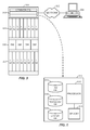
- FIG. 3 is a block diagram of a node 300 for suppressing invalid defect detection when Out-Of-Frame (OOF) conditions occur within the network.
- the node 300 may be embodied by an optical switch utilizing SONET, SDH, OTN, and the like.
- the node 300 may consolidate the functionality of a multi-service provisioning platform (MSPP), SONET/SDH digital cross connect (DCS), Ethernet and Optical Transport Network (OTN) switch, dense wave division multiplexed (DWDM) platform, etc. into a single, high-capacity intelligent switching system providing layer 0, 1, and 2 consolidation.
- the node 300 may include common equipment 310 , line modules (LM) 320 , and switch modules (SM) 330 .
- LM line modules
- SM switch modules
- the common equipment 310 may include power, a control module (CM) 512 (shown in detail in FIG. 5 ), operations, administration, maintenance, and provisioning (OAM&P) access, and the like.
- CM control module
- OAM&P operations, administration, maintenance, and provisioning
- the common equipment 310 may connect to a management system 304 through a data communication network 302 .
- the management system 304 may include a network management system (NMS), element management system (EMS), or the like.
- the common equipment 310 may include a control plane processor configured to operate the control plane and the systems and methods described herein with regard to invalid defect suppression.
- the line modules (LM) 320 may be communicatively coupled to the switch modules (SM) 330 , such as through a backplane, mid-plane, or the like.
- the line modules (LM) 320 may be configured to provide ingress and egress to the switch modules (SM) 330 , and are configured to provide interfaces for the OTN services described herein.
- the line modules (LM) 320 may form ingress and egress switches with the switch modules (SM) 330 as center stage switches for a three-stage switch, e.g. three stage Clos switch.
- the line modules (LM) 320 may include optical transceivers, such as, for example, 2.5 Gb/s (OC-48/STM-1, OTU1, ODU1), 10 Gb/s (OC-192/STM-64, OTU2, ODU2), 40 Gb/s (OC-768/STM-256, OTTO, ODU4), etc.
- the line modules (LM) 320 may include a plurality of optical connections per module and each module may include a flexible rate support for any type of connection, such as, for example, 155 Mb/s, 622 Mb/s, 1 Gb/s, 2.5 Gb/s, 10 Gb/s, 40 Gb/s, and 100 Gb/s.
- the line modules (LM) 320 may include DWDM interfaces, short reach interfaces, and the like, and may connect to other line modules (LM) 320 on remote switch, nodes, end clients, and the like. From a logical perspective, the line modules (LM) 320 provide ingress and egress ports to the node 300 , and each line module (LM) 320 may include one or more physical ports.
- the node 300 may include software and the like to track logical objects such as connection termination points, trail termination points, etc. associated with the line modules (LM) 320 .
- the switch modules (SM) 330 are configured to switch services between the line modules (LM) 320 .
- the switch modules (SM) 330 may provide wavelength granularity, SONET/SDH granularity such as Synchronous Transport Signal-1 (STS-1), Synchronous Transport Module level 1 (STM-1), Virtual Container 3 (VC3), etc.; OTN granularity such as Optical Channel Data Unit-1 (ODU1), Optical Channel Data Unit-2 (ODU2), Optical Channel Data Unit-3 (ODU3), Optical Channel Data Unit-4 (ODU4), Optical channel Pay load Virtual Containers (OPVCs), etc.; Ethernet granularity; and the like.
- SONET/SDH granularity such as Synchronous Transport Signal-1 (STS-1), Synchronous Transport Module level 1 (STM-1), Virtual Container 3 (VC3), etc.
- OTN granularity such as Optical Channel Data Unit-1 (ODU1), Optical Channel Data Unit-2 (ODU2), Optical Channel Data Unit
- the switch modules (SM) 330 may include both Time Division Multiplexed (TDM) and packet switching engines.
- the switch modules (SM) 330 may include redundancy as well, such as 1:1, 1:N, etc.
- the line modules (LM) 320 and the switch modules (SM) 330 are configured to manage and provide SONET, SDH, and OTN line signals. That is, the line modules (LM) 320 and the switch modules (SM) 330 may be line terminating in terms of SONET, SDH, and OTN overhead.
- FIG. 4 is a block diagram illustrating an exemplary network 400 consistent with embodiments of the invention.
- the network 400 may include a plurality of nodes 420 a - 420 f interconnected with optical links 406 .
- the network 400 is illustrated with the nodes 420 forming mesh architecture; however the systems and methods described herein are equally applicable to other architectures, such as rings, linear, and the like.
- the optical links 406 may include optical fiber carrying one or more wavelengths between adjacent nodes 420 .
- the network 400 may also include a control plane 410 which may operate a signaling and routing protocol.
- control plane 410 may include Optical Signaling and Routing Protocol (OSRP), Automatically Switched Optical Networks ITU-T Recommendation G.8080: Architecture for the Automatically Switched Optical Network (ASON) 2001, Generalized Multi-Protocol Label Switching Architecture (G-MPLS) IETF RFC 3945, 2004, and the like.
- the control plane 410 may perform functions such as automatic resource discovery, distributing network resource information, establishing and restoring connections dynamically across the network, and the like.
- One or more nodes may be a line terminating equipment (LTE) network element and typically will not participate in the control plane 410 .
- the optical switch 420 d may be a legacy network element, may be a submarine LTE network element, may be from a different equipment vendor, may belong to another operator, or the like.
- nodes which perform suppression of invalid defects during OOF conditions will typically be functionally coupled to the control plane, and thus serve as control plane link termination points (e.g., nodes 420 a , 420 b , 420 c , 420 e , and 420 f are the control plane link termination points shown in FIG. 4 ).
- FIG. 5 shows an exemplary embodiment of a control module (CM) 512 associated with the node 300 which may perform invalid defect suppression when OOF conditions occur within the network.
- the CM 512 may be part of the common equipment 310 in the node 300 as shown in FIG. 3 .
- the CM 512 may include a processor 515 which may be a hardware device for executing software instructions stored in an associated memory 519 .
- the processor 515 may be any custom made or commercially available processor, a central processing unit (CPU), an auxiliary processor among several processors associated with the CM 512 , a semiconductor-based microprocessor (in the form of a microchip or chip set), or generally any device for executing software instructions.
- processor 515 may be a custom designed ASIC.
- the processor 515 can be configured to execute software stored within memory 519 , to communicate data to and from the memory 519 , and/or to generally control operations of the CM 512 pursuant to the software instructions.
- the CM 512 may also include network interfaces, a data store, and the like.
- the network interfaces may be used to enable the CM 512 to communicate on a network, such as to communicate control plane information to other CMs.
- the network interfaces may include, for example, an Ethernet card (e.g., 10BaseT, Fast Ethernet, Gigabit Ethernet) or a wireless local area network (WLAN) card (e.g., 802.11a/b/g).
- the network interfaces may include address, control, and/or data connections to enable appropriate communications on the network.
- the data store may be used to store data, such as control plane information received from other nodes, and/or their CMs, etc.
- the data store may include any of volatile memory elements (e.g., random access memory (RAM, such as DRAM, SRAM, SDRAM, and the like)), nonvolatile memory elements (e.g., ROM, hard drive, tape, CDROM, and the like), and combinations thereof. Moreover, the data store may incorporate electronic, magnetic, optical, and/or other types of storage media.
- the memory may include any of volatile memory elements (e.g., random access memory (RAM, such as DRAM, SRAM, SDRAM, etc.)), nonvolatile memory elements (e.g., ROM, hard drive, tape, CDROM, etc.), and combinations thereof. Moreover, the memory may incorporate electronic, magnetic, optical, and/or other types of storage media. Note that the memory may have a distributed architecture, where various components are situated remotely from one another, but may be accessed by the processor.
- the CM 512 may further include a link database (DB) 514 , a topology DB 516 , and/or a circuit DB 518 functionally coupled to processor 515 .
- the CM 512 may be responsible for all control plane processing associated with the node 300 , and further perform invalid defect suppression when OOF conditions occur within the network.
- the control plane may include OSRP, ASON, G-MPLS, or the like. It may perform many functions such as automatic resource discovery, distributing network resource information, establishing and restoring connections dynamically across the network, and the like.
- the present invention is not limited to OSRP, as other intelligent signaling and routing protocols that can (or can be modified to) provide similar functionality as OSRP (e.g., automatically establishing and restoring connections across the network, and the like) may be used.
- the DBs 514 , 516 , 518 may be stored in the memory and/or some other data store.
- the link DB 514 includes updated information related to each link in a network.
- the topology DB 516 includes updated information related to the network topology, and the circuit DB 518 includes a listing of terminating circuits and transiting circuits at a node where the CM 512 is located.
- the CM 512 may utilize control plane mechanisms to maintain the DBs 514 , 516 , 518 .
- a HELLO protocol can be used to discover and verify neighboring ports, nodes, protection bundles, and the like.
- the DBs 514 , 516 , 518 may share topology state messages to exchange information to maintain identical data.
- the processor 515 and the DBs 514 , 516 , 518 may be utilized to advertise topology information, capacity availability, create and manage trail termination points, and provide connection management (provisioning and restoration).
- each link in a network may have various attributes associated with it, such as, for example, line protection, available capacity, total capacity, administrative weight, protection bundle identification, delay, and the like.
- the processor 515 and the DBs 514 , 516 , 518 may be configured to provide automated end-to-end provisioning.
- the CM 512 is configured to communicate to other CMs 512 in other nodes on the network. This communication may be either in-band or out-of-band.
- the present invention includes an in-band signaling mechanism utilizing SONET, SDH, or OTN overhead.
- the General Communication Channels (GCC) defined by ITU-T Recommendation G.709 “Interfaces for the optical transport network (OTN)” G.709 are in-band side channel used to carry transmission management and signaling information within Optical Transport Network elements.
- the GCC channels include GCCO and GCC 1/2.
- GCCO are two bytes within Optical Channel Transport Unit-k (OTUk) overhead that are terminated at every 3 R (Re-shaping, Re-timing, Re-amplification) point.
- GCC1/2 are four bytes (i.e. each of GCC1 and GCC2 include two bytes) within Optical Channel Data Unit-k (ODUk) overhead.
- GCCO, GCC1, GCC2 or GCC 1+2 may be used for in-band signaling or routing to carry control plane traffic. Based on the intermediate equipment's termination layer, different bytes may be used to carry control plane traffic. If the ODU layer has faults, it has been ensured not to disrupt the GCC1 and GCC2 overhead bytes and thus achieving the proper delivery control plane packets.
- FIG. 6 is a flowchart showing an exemplary process 600 for suppressing invalid defects during OOF conditions.
- the process 600 may be performed at one or more downstream nodes serving as control plane link termination points.
- process 600 may detect an OOF condition ( 602 ).
- the OOF condition may be caused by the change in timing of the OTUk frame due to ODUk timing changes.
- the process may detect an indication of a defect caused by the OOF condition ( 604 ).
- Such defects are invalid defects as they are caused by, for example, the shift in the OTUk frame. Accordingly, the process may suppress the reporting of the detected defect for the time being ( 606 ).
- the process may then determine whether the OOF condition is clear ( 608 ).
- a threshold may be 3 milliseconds
- the process 600 may then check whether the indication of the defect is still present ( 610 ). If so, the node may provide a report to the control plane that an actual defect exists ( 614 ). If the indication of the defect is no longer present, then the process will cancel (e.g., not provide) any report indicating a status byte defect ( 612 ).
- a software module may reside in RAM memory, flash memory, ROM memory, EPROM memory, EEPROM memory, registers, hard disk, a removable disk, a CD-ROM, or any other form of storage medium known in the art.
- An exemplary storage medium is coupled to the processor such that the processor can read information from, and write information to, the storage medium. In the alternative, the storage medium may be integral to the processor.
Landscapes
- Engineering & Computer Science (AREA)
- Computer Networks & Wireless Communication (AREA)
- Signal Processing (AREA)
- Environmental & Geological Engineering (AREA)
- Time-Division Multiplex Systems (AREA)
- Physics & Mathematics (AREA)
- Electromagnetism (AREA)
- Data Exchanges In Wide-Area Networks (AREA)
Abstract
Description
Claims (19)
Priority Applications (1)
| Application Number | Priority Date | Filing Date | Title |
|---|---|---|---|
| US13/868,343 US10044457B2 (en) | 2013-04-23 | 2013-04-23 | Preventing invalid defect detection during OTN out-of-frame states |
Applications Claiming Priority (1)
| Application Number | Priority Date | Filing Date | Title |
|---|---|---|---|
| US13/868,343 US10044457B2 (en) | 2013-04-23 | 2013-04-23 | Preventing invalid defect detection during OTN out-of-frame states |
Publications (2)
| Publication Number | Publication Date |
|---|---|
| US20140314402A1 US20140314402A1 (en) | 2014-10-23 |
| US10044457B2 true US10044457B2 (en) | 2018-08-07 |
Family
ID=51729080
Family Applications (1)
| Application Number | Title | Priority Date | Filing Date |
|---|---|---|---|
| US13/868,343 Active 2034-09-20 US10044457B2 (en) | 2013-04-23 | 2013-04-23 | Preventing invalid defect detection during OTN out-of-frame states |
Country Status (1)
| Country | Link |
|---|---|
| US (1) | US10044457B2 (en) |
Cited By (2)
| Publication number | Priority date | Publication date | Assignee | Title |
|---|---|---|---|---|
| EP4004842A1 (en) * | 2019-07-31 | 2022-06-01 | Hitachi Energy Switzerland AG | Autonomous semantic data discovery for distributed networked systems |
| US12375173B2 (en) * | 2020-06-02 | 2025-07-29 | Huawei Technologies Co., Ltd. | Alarm processing method and apparatus |
Families Citing this family (6)
| Publication number | Priority date | Publication date | Assignee | Title |
|---|---|---|---|---|
| JP6323070B2 (en) * | 2014-03-03 | 2018-05-16 | 富士通株式会社 | Optical receiving apparatus and optical receiving method |
| US9553661B2 (en) | 2015-05-18 | 2017-01-24 | Ciena Corporation | Adaptive preconfiguration in optical transport network |
| US9848049B2 (en) | 2015-10-06 | 2017-12-19 | Ciena Corporation | Service preemption selection systems and methods in networks |
| US9832548B2 (en) | 2016-01-29 | 2017-11-28 | Ciena Corporation | Flexible behavior modification during restoration in optical networks |
| US11122346B1 (en) * | 2020-06-25 | 2021-09-14 | Cisco Technology, Inc. | Attestation in optical transport network environments |
| US12400528B2 (en) | 2022-02-14 | 2025-08-26 | Ciena Corporation | Guided cable assist of networking hardware |
Citations (12)
| Publication number | Priority date | Publication date | Assignee | Title |
|---|---|---|---|---|
| US6795451B1 (en) * | 2000-03-17 | 2004-09-21 | Applied Micro Circuits Corporation | Programmable synchronization structure with auxiliary data link |
| US7035292B1 (en) * | 2000-03-17 | 2006-04-25 | Applied Micro Circuits Corporation | Transposable frame synchronization structure |
| US7602814B2 (en) | 2007-04-30 | 2009-10-13 | Ciena Corporation | Systems and methods for mapping and multiplexing wider clock tolerance signals in optical transport network transponders and multiplexers |
| US20100054731A1 (en) | 2008-09-02 | 2010-03-04 | Ciena Corporation | Methods and systems for the hierarchical mesh restoration of connections in an automatically switched optical network |
| US8059685B2 (en) | 2006-12-26 | 2011-11-15 | Ciena Corporation | Methods and systems for carrying synchronization over Ethernet and optical transport network |
| US20120106950A1 (en) | 2010-11-03 | 2012-05-03 | Ciena Corporation | Method and system for optical network smart timer management via delay measurement between spans |
| US20120106948A1 (en) | 2010-10-28 | 2012-05-03 | Jeffrey Scott Moynihan | Optical network in-band control plane signaling, virtualized channels, and tandem connection monitoring systems and methods |
| US8204382B2 (en) | 2009-03-11 | 2012-06-19 | Ciena Corporation | Radio frequency-based optical transport network systems and methods |
| US20120213508A1 (en) | 2011-02-23 | 2012-08-23 | Jeffrey Scott Moynihan | Network element clock synchronization systems and methods using optical transport network delay measurement |
| US8259733B2 (en) | 2009-04-27 | 2012-09-04 | Ciena Corporation | Systems and methods for rapid optical transport network circuit provisioning |
| US8356233B2 (en) | 2010-05-19 | 2013-01-15 | Ciena Corporation | Pseudo-noise insertion on unacceptable input data sequence in optical networks |
| US20130051792A1 (en) * | 2011-08-24 | 2013-02-28 | Alexander A. Smith | Systems and methods for detecting line flapping in optical networks |
-
2013
- 2013-04-23 US US13/868,343 patent/US10044457B2/en active Active
Patent Citations (12)
| Publication number | Priority date | Publication date | Assignee | Title |
|---|---|---|---|---|
| US6795451B1 (en) * | 2000-03-17 | 2004-09-21 | Applied Micro Circuits Corporation | Programmable synchronization structure with auxiliary data link |
| US7035292B1 (en) * | 2000-03-17 | 2006-04-25 | Applied Micro Circuits Corporation | Transposable frame synchronization structure |
| US8059685B2 (en) | 2006-12-26 | 2011-11-15 | Ciena Corporation | Methods and systems for carrying synchronization over Ethernet and optical transport network |
| US7602814B2 (en) | 2007-04-30 | 2009-10-13 | Ciena Corporation | Systems and methods for mapping and multiplexing wider clock tolerance signals in optical transport network transponders and multiplexers |
| US20100054731A1 (en) | 2008-09-02 | 2010-03-04 | Ciena Corporation | Methods and systems for the hierarchical mesh restoration of connections in an automatically switched optical network |
| US8204382B2 (en) | 2009-03-11 | 2012-06-19 | Ciena Corporation | Radio frequency-based optical transport network systems and methods |
| US8259733B2 (en) | 2009-04-27 | 2012-09-04 | Ciena Corporation | Systems and methods for rapid optical transport network circuit provisioning |
| US8356233B2 (en) | 2010-05-19 | 2013-01-15 | Ciena Corporation | Pseudo-noise insertion on unacceptable input data sequence in optical networks |
| US20120106948A1 (en) | 2010-10-28 | 2012-05-03 | Jeffrey Scott Moynihan | Optical network in-band control plane signaling, virtualized channels, and tandem connection monitoring systems and methods |
| US20120106950A1 (en) | 2010-11-03 | 2012-05-03 | Ciena Corporation | Method and system for optical network smart timer management via delay measurement between spans |
| US20120213508A1 (en) | 2011-02-23 | 2012-08-23 | Jeffrey Scott Moynihan | Network element clock synchronization systems and methods using optical transport network delay measurement |
| US20130051792A1 (en) * | 2011-08-24 | 2013-02-28 | Alexander A. Smith | Systems and methods for detecting line flapping in optical networks |
Non-Patent Citations (8)
| Title |
|---|
| Agilent Technologies, "An Overview of ITU-T G.709. Application Note: 1379." pp. 1-12. |
| Ciena, "OTN Outperforms SONET/SDH." White Paper. Linthicum, MD. www.ciena.com. pp. 1-7. |
| Ciena, "The Value of OTN for Network Convergence and IP/Ethernet Migration" White Paper. Linthicum, MD. www.ciena.com, pp. 1-3. |
| Fujitsu Network Communications Inc., "The Key Benefits of OTN Networks." Richardson, Texas. us.fujitsu.com/telecom. pp. 1-8. |
| G709 OTN "Optical Transport Network Tutorial", Guylain Barlow, 2009 (JDSU white paper). * |
| Gendron, R. and Gidaro, A., "The G.709 Optical Transport Network-An Overview. Application Note 153." EXFO Expertise Reaching Out. Telecom Test and Measurement. 2006 EXFO Electro-Optical Engineering Inc. Jun. 2009. |
| Gendron, R. and Gidaro, A., "The G.709 Optical Transport Network—An Overview. Application Note 153." EXFO Expertise Reaching Out. Telecom Test and Measurement. 2006 EXFO Electro-Optical Engineering Inc. Jun. 2009. |
| ITU, "Optical Transport Network (OTN) Tutorial." Contact: Timothy P. Walker, twalker@amcc.com. AMCC, USA. pp. 1-62. |
Cited By (3)
| Publication number | Priority date | Publication date | Assignee | Title |
|---|---|---|---|---|
| EP4004842A1 (en) * | 2019-07-31 | 2022-06-01 | Hitachi Energy Switzerland AG | Autonomous semantic data discovery for distributed networked systems |
| EP4004842B1 (en) * | 2019-07-31 | 2025-11-05 | Hitachi Energy Ltd | Autonomous semantic data discovery for distributed networked systems |
| US12375173B2 (en) * | 2020-06-02 | 2025-07-29 | Huawei Technologies Co., Ltd. | Alarm processing method and apparatus |
Also Published As
| Publication number | Publication date |
|---|---|
| US20140314402A1 (en) | 2014-10-23 |
Similar Documents
| Publication | Publication Date | Title |
|---|---|---|
| US8417111B2 (en) | Optical network in-band control plane signaling, virtualized channels, and tandem connection monitoring systems and methods | |
| US9240905B2 (en) | Protecting hybrid equipment in a network node | |
| US9680588B2 (en) | OTN switching systems and methods using an SDN controller and match/action rules | |
| US10826604B2 (en) | Fault localization using tandem connection monitors in optical transport network | |
| US9143227B2 (en) | Optical transport network port protection systems and methods using flexible switch criteria | |
| US10044457B2 (en) | Preventing invalid defect detection during OTN out-of-frame states | |
| US8457001B2 (en) | Mesh restoration in optical transport networks | |
| US9853722B1 (en) | Systems and methods for path protection switching due to client protection switching | |
| US10257596B2 (en) | Systems and methods for managing excess optical capacity and margin in optical networks | |
| EP2983314B1 (en) | Oduflex resizing systems and methods | |
| US9264139B2 (en) | Optical transport network clock transient suppression systems and methods | |
| US8958701B2 (en) | Methods and systems of preserving client overhead bytes in optical transport network tunneling applications | |
| US9088380B2 (en) | Optical transport network generic non-client specific protection systems and methods | |
| US9455788B2 (en) | Hitless modulation scheme change systems and methods in optical networks | |
| US9628172B2 (en) | Optimization of photonic services with colorless and directionless architecture | |
| US10951963B2 (en) | Fast mesh restoration systems and method with real time detection of fault location | |
| US20130266312A1 (en) | Optical transport network transient management systems and methods | |
| US9917668B2 (en) | Systems and methods for detecting and propagating resizability information of oduflex connections | |
| US9538573B2 (en) | Systems and methods for managing call connections from non-originating nodes in networks | |
| US8817824B2 (en) | Optical transport network line management system and methods | |
| US9825696B2 (en) | Ethernet link state signaling for packet flows mapped into optical transport network with generic framing procedure | |
| US9237090B2 (en) | Network routing systems and methods for validation of paths subsequent to validation failure | |
| US8682158B2 (en) | Systems and methods for detecting line flapping in optical networks | |
| US9762340B1 (en) | Synchronization timing loop detection systems and methods | |
| EP2713536A2 (en) | Optical transport network generic non-client specific protection systems and methods |
Legal Events
| Date | Code | Title | Description |
|---|---|---|---|
| AS | Assignment |
Owner name: CIENA CORPORATION, MARYLAND Free format text: ASSIGNMENT OF ASSIGNORS INTEREST;ASSIGNORS:MOYNIHAN, JEFFREY SCOTT;CONNOLLY, MATTHEW W.;REEL/FRAME:030265/0301 Effective date: 20130418 |
|
| AS | Assignment |
Owner name: DEUTSCHE BANK AG NEW YORK BRANCH, NEW YORK Free format text: SECURITY INTEREST;ASSIGNOR:CIENA CORPORATION;REEL/FRAME:033329/0417 Effective date: 20140715 |
|
| AS | Assignment |
Owner name: BANK OF AMERICA, N.A., AS ADMINISTRATIVE AGENT, NORTH CAROLINA Free format text: PATENT SECURITY AGREEMENT;ASSIGNOR:CIENA CORPORATION;REEL/FRAME:033347/0260 Effective date: 20140715 Owner name: BANK OF AMERICA, N.A., AS ADMINISTRATIVE AGENT, NO Free format text: PATENT SECURITY AGREEMENT;ASSIGNOR:CIENA CORPORATION;REEL/FRAME:033347/0260 Effective date: 20140715 |
|
| STCF | Information on status: patent grant |
Free format text: PATENTED CASE |
|
| AS | Assignment |
Owner name: CIENA CORPORATION, MARYLAND Free format text: RELEASE BY SECURED PARTY;ASSIGNOR:DEUTSCHE BANK AG NEW YORK BRANCH;REEL/FRAME:050938/0389 Effective date: 20191028 |
|
| AS | Assignment |
Owner name: BANK OF AMERICA, N.A., AS COLLATERAL AGENT, ILLINO Free format text: PATENT SECURITY AGREEMENT;ASSIGNOR:CIENA CORPORATION;REEL/FRAME:050969/0001 Effective date: 20191028 Owner name: BANK OF AMERICA, N.A., AS COLLATERAL AGENT, ILLINOIS Free format text: PATENT SECURITY AGREEMENT;ASSIGNOR:CIENA CORPORATION;REEL/FRAME:050969/0001 Effective date: 20191028 |
|
| MAFP | Maintenance fee payment |
Free format text: PAYMENT OF MAINTENANCE FEE, 4TH YEAR, LARGE ENTITY (ORIGINAL EVENT CODE: M1551); ENTITY STATUS OF PATENT OWNER: LARGE ENTITY Year of fee payment: 4 |
|
| AS | Assignment |
Owner name: CIENA CORPORATION, MARYLAND Free format text: RELEASE BY SECURED PARTY;ASSIGNOR:BANK OF AMERICA, N.A.;REEL/FRAME:065630/0232 Effective date: 20231024 |
|
| MAFP | Maintenance fee payment |
Free format text: PAYMENT OF MAINTENANCE FEE, 8TH YEAR, LARGE ENTITY (ORIGINAL EVENT CODE: M1552); ENTITY STATUS OF PATENT OWNER: LARGE ENTITY Year of fee payment: 8 |