US10044113B2 - Two-way crimpless butt connector - Google Patents
Two-way crimpless butt connector Download PDFInfo
- Publication number
- US10044113B2 US10044113B2 US15/620,906 US201715620906A US10044113B2 US 10044113 B2 US10044113 B2 US 10044113B2 US 201715620906 A US201715620906 A US 201715620906A US 10044113 B2 US10044113 B2 US 10044113B2
- Authority
- US
- United States
- Prior art keywords
- butt connector
- conduit
- cylindrical
- housing
- diameter
- Prior art date
- Legal status (The legal status is an assumption and is not a legal conclusion. Google has not performed a legal analysis and makes no representation as to the accuracy of the status listed.)
- Expired - Fee Related
Links
- 229910001369 Brass Inorganic materials 0.000 claims description 4
- RYGMFSIKBFXOCR-UHFFFAOYSA-N Copper Chemical compound [Cu] RYGMFSIKBFXOCR-UHFFFAOYSA-N 0.000 claims description 4
- PXHVJJICTQNCMI-UHFFFAOYSA-N Nickel Chemical compound [Ni] PXHVJJICTQNCMI-UHFFFAOYSA-N 0.000 claims description 4
- 229910052782 aluminium Inorganic materials 0.000 claims description 4
- XAGFODPZIPBFFR-UHFFFAOYSA-N aluminium Chemical compound [Al] XAGFODPZIPBFFR-UHFFFAOYSA-N 0.000 claims description 4
- 239000010951 brass Substances 0.000 claims description 4
- 239000004020 conductor Substances 0.000 claims description 4
- 229910052802 copper Inorganic materials 0.000 claims description 4
- 239000010949 copper Substances 0.000 claims description 4
- 238000003780 insertion Methods 0.000 claims description 3
- 230000037431 insertion Effects 0.000 claims description 3
- 229920001084 poly(chloroprene) Polymers 0.000 claims description 3
- -1 polyethylene Polymers 0.000 claims description 3
- 239000004800 polyvinyl chloride Substances 0.000 claims description 3
- 239000004677 Nylon Substances 0.000 claims description 2
- 239000004698 Polyethylene Substances 0.000 claims description 2
- 239000004642 Polyimide Substances 0.000 claims description 2
- HCHKCACWOHOZIP-UHFFFAOYSA-N Zinc Chemical compound [Zn] HCHKCACWOHOZIP-UHFFFAOYSA-N 0.000 claims description 2
- 239000000853 adhesive Substances 0.000 claims description 2
- 230000001070 adhesive effect Effects 0.000 claims description 2
- 239000012212 insulator Substances 0.000 claims description 2
- 229910052759 nickel Inorganic materials 0.000 claims description 2
- 229920001778 nylon Polymers 0.000 claims description 2
- 229920000573 polyethylene Polymers 0.000 claims description 2
- 229920001721 polyimide Polymers 0.000 claims description 2
- 229920000915 polyvinyl chloride Polymers 0.000 claims description 2
- 229910052725 zinc Inorganic materials 0.000 claims description 2
- 239000011701 zinc Substances 0.000 claims description 2
- 238000012986 modification Methods 0.000 description 3
- 230000004048 modification Effects 0.000 description 3
- 238000002788 crimping Methods 0.000 description 2
- 230000005611 electricity Effects 0.000 description 2
- 239000000463 material Substances 0.000 description 2
- 229910052751 metal Inorganic materials 0.000 description 2
- 239000002184 metal Substances 0.000 description 2
- 229920002449 FKM Polymers 0.000 description 1
- 239000004812 Fluorinated ethylene propylene Substances 0.000 description 1
- 239000002033 PVDF binder Substances 0.000 description 1
- 238000010276 construction Methods 0.000 description 1
- 238000009429 electrical wiring Methods 0.000 description 1
- HQQADJVZYDDRJT-UHFFFAOYSA-N ethene;prop-1-ene Chemical group C=C.CC=C HQQADJVZYDDRJT-UHFFFAOYSA-N 0.000 description 1
- 231100001261 hazardous Toxicity 0.000 description 1
- 239000012774 insulation material Substances 0.000 description 1
- 229920009441 perflouroethylene propylene Polymers 0.000 description 1
- 229920000098 polyolefin Polymers 0.000 description 1
- 229920001343 polytetrafluoroethylene Polymers 0.000 description 1
- 239000004810 polytetrafluoroethylene Substances 0.000 description 1
- 229920002981 polyvinylidene fluoride Polymers 0.000 description 1
- 229920002379 silicone rubber Polymers 0.000 description 1
- 239000012815 thermoplastic material Substances 0.000 description 1
Images


Classifications
-
- H—ELECTRICITY
- H01—ELECTRIC ELEMENTS
- H01R—ELECTRICALLY-CONDUCTIVE CONNECTIONS; STRUCTURAL ASSOCIATIONS OF A PLURALITY OF MUTUALLY-INSULATED ELECTRICAL CONNECTING ELEMENTS; COUPLING DEVICES; CURRENT COLLECTORS
- H01R4/00—Electrically-conductive connections between two or more conductive members in direct contact, i.e. touching one another; Means for effecting or maintaining such contact; Electrically-conductive connections having two or more spaced connecting locations for conductors and using contact members penetrating insulation
- H01R4/10—Electrically-conductive connections between two or more conductive members in direct contact, i.e. touching one another; Means for effecting or maintaining such contact; Electrically-conductive connections having two or more spaced connecting locations for conductors and using contact members penetrating insulation effected solely by twisting, wrapping, bending, crimping, or other permanent deformation
- H01R4/16—Electrically-conductive connections between two or more conductive members in direct contact, i.e. touching one another; Means for effecting or maintaining such contact; Electrically-conductive connections having two or more spaced connecting locations for conductors and using contact members penetrating insulation effected solely by twisting, wrapping, bending, crimping, or other permanent deformation by bending
-
- H—ELECTRICITY
- H01—ELECTRIC ELEMENTS
- H01R—ELECTRICALLY-CONDUCTIVE CONNECTIONS; STRUCTURAL ASSOCIATIONS OF A PLURALITY OF MUTUALLY-INSULATED ELECTRICAL CONNECTING ELEMENTS; COUPLING DEVICES; CURRENT COLLECTORS
- H01R4/00—Electrically-conductive connections between two or more conductive members in direct contact, i.e. touching one another; Means for effecting or maintaining such contact; Electrically-conductive connections having two or more spaced connecting locations for conductors and using contact members penetrating insulation
- H01R4/22—End caps, i.e. of insulating or conductive material for covering or maintaining connections between wires entering the cap from the same end
-
- H—ELECTRICITY
- H01—ELECTRIC ELEMENTS
- H01R—ELECTRICALLY-CONDUCTIVE CONNECTIONS; STRUCTURAL ASSOCIATIONS OF A PLURALITY OF MUTUALLY-INSULATED ELECTRICAL CONNECTING ELEMENTS; COUPLING DEVICES; CURRENT COLLECTORS
- H01R4/00—Electrically-conductive connections between two or more conductive members in direct contact, i.e. touching one another; Means for effecting or maintaining such contact; Electrically-conductive connections having two or more spaced connecting locations for conductors and using contact members penetrating insulation
- H01R4/24—Connections using contact members penetrating or cutting insulation or cable strands
- H01R4/2404—Connections using contact members penetrating or cutting insulation or cable strands the contact members having teeth, prongs, pins or needles penetrating the insulation
-
- H—ELECTRICITY
- H01—ELECTRIC ELEMENTS
- H01R—ELECTRICALLY-CONDUCTIVE CONNECTIONS; STRUCTURAL ASSOCIATIONS OF A PLURALITY OF MUTUALLY-INSULATED ELECTRICAL CONNECTING ELEMENTS; COUPLING DEVICES; CURRENT COLLECTORS
- H01R4/00—Electrically-conductive connections between two or more conductive members in direct contact, i.e. touching one another; Means for effecting or maintaining such contact; Electrically-conductive connections having two or more spaced connecting locations for conductors and using contact members penetrating insulation
- H01R4/26—Connections in which at least one of the connecting parts has projections which bite into or engage the other connecting part in order to improve the contact
-
- H—ELECTRICITY
- H01—ELECTRIC ELEMENTS
- H01R—ELECTRICALLY-CONDUCTIVE CONNECTIONS; STRUCTURAL ASSOCIATIONS OF A PLURALITY OF MUTUALLY-INSULATED ELECTRICAL CONNECTING ELEMENTS; COUPLING DEVICES; CURRENT COLLECTORS
- H01R4/00—Electrically-conductive connections between two or more conductive members in direct contact, i.e. touching one another; Means for effecting or maintaining such contact; Electrically-conductive connections having two or more spaced connecting locations for conductors and using contact members penetrating insulation
- H01R4/58—Electrically-conductive connections between two or more conductive members in direct contact, i.e. touching one another; Means for effecting or maintaining such contact; Electrically-conductive connections having two or more spaced connecting locations for conductors and using contact members penetrating insulation characterised by the form or material of the contacting members
- H01R4/64—Connections between or with conductive parts having primarily a non-electric function, e.g. frame, casing, rail
- H01R4/646—Connections between or with conductive parts having primarily a non-electric function, e.g. frame, casing, rail for cables or flexible cylindrical bodies
-
- H—ELECTRICITY
- H01—ELECTRIC ELEMENTS
- H01R—ELECTRICALLY-CONDUCTIVE CONNECTIONS; STRUCTURAL ASSOCIATIONS OF A PLURALITY OF MUTUALLY-INSULATED ELECTRICAL CONNECTING ELEMENTS; COUPLING DEVICES; CURRENT COLLECTORS
- H01R4/00—Electrically-conductive connections between two or more conductive members in direct contact, i.e. touching one another; Means for effecting or maintaining such contact; Electrically-conductive connections having two or more spaced connecting locations for conductors and using contact members penetrating insulation
- H01R4/70—Insulation of connections
- H01R4/72—Insulation of connections using a heat shrinking insulating sleeve
Definitions
- the present invention relates to electrical connectors. More specifically, the present invention relates to a two-way butt connector including an interior conductive housing and a fastener configured to adjoin and secure two ends of a wire within the housing without the need of a crimper.
- a crimping tool is a device used to conjoin two pieces of metal, such as two electrical wires, by deforming one or both of them in a way that causes them to hold each other.
- the bend or deformity resulting from the tool's work is called a crimp, which ensures that the two pieces of metal have been conjoined.
- crimping tools, or crimpers are employed in order to repair or join damaged or broken wires.
- the crimper is commonly employed with a butt connector to terminate the wires safely.
- Butt connectors include an external insulating area and a bore including a conductive housing, or conduit that receives two ends, or butts, of a wire into either side. Upon insertion of the wire ends into the conduit, the butt connector is crimped around the two wire ends, thereby securing the wire ends to one another and establishing an electrical connection therebetween.
- the present invention provides a two-way crimpless butt connector wherein the same can be utilized for providing convenience for the user when repairing or joining broken or damaged wires.
- the two-way crimpless butt connector includes a cylindrical housing including a first end, a second end, and a middle portion.
- a longitudinal bore extends longitudinally through the housing from the first end to the second end.
- the first and second ends each include an opening for providing access to the longitudinal bore.
- a cylindrical conduit including a first and second end is disposed longitudinally in the longitudinal bore.
- a plurality of teeth disposed annularly, at fixed intervals, about a perimeter edge of the first and second ends of the conduit extend radially inwardly.
- Each of the plurality of teeth define an opening at the first and second end that includes a diameter less than a diameter of a wire end.
- the plurality of teeth are configured to bend inwardly upon insertion of a wire end into the conduit, such that they can grasp the wire end inserted therein.
- FIG. 1 shows a perspective view of the two-way crimpless butt connector.
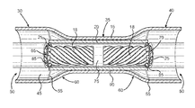
- FIG. 2 shows a cross-sectional view of the two-way crimpless butt connector along a longitudinal axis.
- FIG. 3 shows a cross-sectional view of the two-way crimpless butt connector along a longitudinal axis illustrating wire ends adjoined within the conduit.
- FIG. 4 shows a perspective view of the two-way crimpless butt connector illustrating the housing secured around the adjoined wire ends.
- FIGS. 1-3 there is shown a perspective view of the two-way crimpless butt connector and cross-sectional views of the two-way crimpless butt connector, along a longitudinal axis, with and without wire ends inserted therein.
- the present invention includes a crimpless butt connector 10 including a cylindrical housing 15 providing two-way entry therein, a cylindrical conduit 20 configured to receive a pair of wire ends 18 therein, and a fastener 25 configured to secure and adjoin the pair of wire ends 18 in the conduit 20 , in order to establish an electrical connection therebetween without the use of a crimper.
- the cylindrical housing 15 includes a first end 30 , a middle portion 35 , a second end 40 , and a longitudinal bore 45 extending longitudinally through the housing 15 from the first end 30 to second end 40 .
- the first and second ends 30 , 40 each include an opening 50 that provides access to the longitudinal bore 45 from either end 30 , 40 of the housing 15 , hence, two-way entry into the housing 15 .
- the first and second ends 30 , 40 flare radially outwardly and include a diameter larger than the diameter of the middle portion 35 , thereby giving the longitudinal bore 45 a larger cross-sectional area at the first and second ends 30 , 40 than at the middle portion 35 of the housing 15 .
- the first end 30 includes a diameter equal to a diameter of the second end 40 .
- the first and second ends 30 , 40 include a flex point 55 , or a point along the housing 15 about which the first and second ends 30 , 40 are configured to bend, thereby enabling the first and second ends 30 , 40 to bend around the pair of wire ends 18 after being inserted into the housing 15 , as illustrated by FIG. 4 .
- the first and second ends 30 , 40 taper radially inwardly towards the middle portion 35 , thereby forming a sloping region 60 , which gives the housing 15 an hourglass shape.
- the housing 15 comprises a pliable insulation material, or a pliable insulator, such as nylon, polyimide, polyvinyl chloride (PVC), neoprene, and polyethylene.
- the housing 15 comprises a heatshrink material, or thermoplastic material, such as polyolefin, polyvinylidene fluoride, polytetrafluoroethylene, fluorinated ethylene propylene, PVC, neoprene, silicone elastomer, and Viton®.
- the cylindrical conduit 20 is disposed within the housing 15 and extends longitudinally through the longitudinal bore 45 .
- the conduit 20 comprises a conductive material such as copper, aluminum, zinc, nickel, and brass, for conducting electricity and establishing a connecting between a pair of wire ends 18 inserted therein.
- the conduit 20 includes a first end 65 , a second end 70 , and a channel 75 defining an interior volume 80 .
- the channel 75 extends longitudinally through the conduit 20 from the first end 65 to the second end 70 .
- the first and second ends 65 , 70 provides access to the channel 75 from either end 65 , 70 of the conduit 20 , i.e., two-way entry into the conduit 20 .
- the conduit 20 is disposed centrally within the housing 15 , such that it is centered along the length of the longitudinal bore 45 .
- the conduit 20 includes a length that is less than the length of the housing 15 , such that the conduit 20 does not extend past the first and second ends 30 , 40 of the housing 15 , but greater than a length of a wire end, such that the conduit 20 can receive the entire length of the wire end therein.
- the conduit 20 includes a length greater than or equal to twice the length of a wire end or a wire, such that it can receive a pair of wire ends therein.
- the conduit 20 is affixed to an interior wall 90 of the housing 15 , via an adhesive, such that the conduit 20 is secured therein.
- the conduit 20 is mounted into the housing 15 via a friction-fit with the interior wall 90 .
- the conduit 20 includes a diameter smaller than the diameter of the housing 15 , such as a diameter equal to the diameter of the longitudinal bore 45 , such that the conduit 20 may be mounted therein.
- the conduit 20 and housing 15 include equal diameters, such that the conduit 20 may be mounted or embedded within the surface of the housing 15 .
- the fastener 25 is disposed annularly about a perimeter edge 85 of the first and second ends 65 , 70 of the conduit 20 .
- the fastener 25 protrudes radially inwardly relative to the conduit 20 .
- the fastener 25 comprises a pliable conductive material configured to bend and conduct electricity, such as copper, aluminum, and brass.
- the fastener 25 includes a plurality of teeth disposed annularly, at fixed intervals, about the perimeter edges 85 .
- the plurality of teeth extend inwardly, forming an opening 88 including a diameter smaller than a diameter of a wire end 18 , as illustrated by FIG. 2 . In this way, the plurality of teeth are configured to make contact with the wire ends 18 when inserted into the conduit 20 , as illustrated by FIG. 3 , in order to establish an electrical connection therebetween.
- the plurality of teeth are further configured to bend inwardly about the perimeter edges 85 towards a center of the conduit 20 , such that when the wire ends 18 are inserted into the conduit 20 , the plurality of teeth bend inwardly grasping the wire ends 18 annularly therearound and holding them securely in the conduit 20 , as illustrated by FIG. 3 .
- the plurality of teeth adjoin the wire ends 18 in the conduit without a crimper and prevent the wire ends 18 from inadvertent egress out the conduit 20 when in use.
- the plurality of teeth are hingedly connected, such as by a living hinge, to the perimeter edges 85 , thereby enabling them to fold inwardly.
- the plurality of teeth are biased outwardly towards their respective ends 65 , 70 , such that they further grasp the wire ends 18 and hold them within the conduit 20 .
Landscapes
- Connections Effected By Soldering, Adhesion, Or Permanent Deformation (AREA)
Abstract
Description
Claims (19)
Priority Applications (1)
| Application Number | Priority Date | Filing Date | Title |
|---|---|---|---|
| US15/620,906 US10044113B2 (en) | 2016-06-13 | 2017-06-13 | Two-way crimpless butt connector |
Applications Claiming Priority (2)
| Application Number | Priority Date | Filing Date | Title |
|---|---|---|---|
| US201662349204P | 2016-06-13 | 2016-06-13 | |
| US15/620,906 US10044113B2 (en) | 2016-06-13 | 2017-06-13 | Two-way crimpless butt connector |
Publications (2)
| Publication Number | Publication Date |
|---|---|
| US20170358871A1 US20170358871A1 (en) | 2017-12-14 |
| US10044113B2 true US10044113B2 (en) | 2018-08-07 |
Family
ID=60574289
Family Applications (1)
| Application Number | Title | Priority Date | Filing Date |
|---|---|---|---|
| US15/620,906 Expired - Fee Related US10044113B2 (en) | 2016-06-13 | 2017-06-13 | Two-way crimpless butt connector |
Country Status (1)
| Country | Link |
|---|---|
| US (1) | US10044113B2 (en) |
Cited By (1)
| Publication number | Priority date | Publication date | Assignee | Title |
|---|---|---|---|---|
| US11769955B1 (en) | 2021-12-26 | 2023-09-26 | John Endacott | Lead free solder sleeve connector with thermal indicator |
Families Citing this family (1)
| Publication number | Priority date | Publication date | Assignee | Title |
|---|---|---|---|---|
| US11113237B1 (en) | 2014-12-30 | 2021-09-07 | EMC IP Holding Company LLC | Solid state cache index for a deduplicate storage system |
Citations (8)
| Publication number | Priority date | Publication date | Assignee | Title |
|---|---|---|---|---|
| US2832816A (en) | 1954-04-26 | 1958-04-29 | Thomas & Betts Corp | Self-insulated two-way butt connector |
| US3143595A (en) * | 1960-12-29 | 1964-08-04 | Thomas & Betts Corp | Polytetrafluoroethylene insulated splice connector |
| US3771112A (en) | 1972-04-07 | 1973-11-06 | J Thompson | Cable splice clamping and bonding assembly |
| US4772235A (en) | 1986-05-16 | 1988-09-20 | Israel Aircraft Industries, Inc. | Electrical connector |
| US6071145A (en) | 1999-02-01 | 2000-06-06 | Toly; Elde V. | Contact housing for electrical connector |
| US7226308B1 (en) | 2006-05-26 | 2007-06-05 | Centerpin Technology, Inc. | Compression snap electrical connector |
| US7256348B1 (en) * | 2006-02-22 | 2007-08-14 | Endacott John E | Step-down in-line butt connector |
| US20100147585A1 (en) | 2008-12-16 | 2010-06-17 | Sumitomo Wiring Systems, Ltd. | Wire connection sleeve, a wire connection sleeve producing method, a repair wire pre-connected with a wire connection sleeve by crimping and a wire connecting method |
-
2017
- 2017-06-13 US US15/620,906 patent/US10044113B2/en not_active Expired - Fee Related
Patent Citations (9)
| Publication number | Priority date | Publication date | Assignee | Title |
|---|---|---|---|---|
| US2832816A (en) | 1954-04-26 | 1958-04-29 | Thomas & Betts Corp | Self-insulated two-way butt connector |
| US3143595A (en) * | 1960-12-29 | 1964-08-04 | Thomas & Betts Corp | Polytetrafluoroethylene insulated splice connector |
| US3771112A (en) | 1972-04-07 | 1973-11-06 | J Thompson | Cable splice clamping and bonding assembly |
| US4772235A (en) | 1986-05-16 | 1988-09-20 | Israel Aircraft Industries, Inc. | Electrical connector |
| US6071145A (en) | 1999-02-01 | 2000-06-06 | Toly; Elde V. | Contact housing for electrical connector |
| US7256348B1 (en) * | 2006-02-22 | 2007-08-14 | Endacott John E | Step-down in-line butt connector |
| US7226308B1 (en) | 2006-05-26 | 2007-06-05 | Centerpin Technology, Inc. | Compression snap electrical connector |
| US20100147585A1 (en) | 2008-12-16 | 2010-06-17 | Sumitomo Wiring Systems, Ltd. | Wire connection sleeve, a wire connection sleeve producing method, a repair wire pre-connected with a wire connection sleeve by crimping and a wire connecting method |
| US8350155B2 (en) * | 2008-12-16 | 2013-01-08 | Sumitomo Wiring Systems, Ltd. | Wire connection sleeve, a wire connection sleeve producing method, a repair wire pre-connected with a wire connection sleeve by crimping and a wire connecting method |
Cited By (1)
| Publication number | Priority date | Publication date | Assignee | Title |
|---|---|---|---|---|
| US11769955B1 (en) | 2021-12-26 | 2023-09-26 | John Endacott | Lead free solder sleeve connector with thermal indicator |
Also Published As
| Publication number | Publication date |
|---|---|
| US20170358871A1 (en) | 2017-12-14 |
Similar Documents
| Publication | Publication Date | Title |
|---|---|---|
| US2429585A (en) | Pressed insulated connector | |
| US7160156B2 (en) | Crimpable wire connector assembly | |
| US20190123467A1 (en) | Female Cabling Connector | |
| CN110914573A (en) | Multi-joint support | |
| US10044113B2 (en) | Two-way crimpless butt connector | |
| US8777679B2 (en) | Electrical connector adapted to receive various diameter cable | |
| US20150096159A1 (en) | Compression Wire Joints | |
| AU761530B2 (en) | No-crimp electrical connector side-by-side type | |
| JP6647185B2 (en) | Cable joint for welding | |
| EP3032675A1 (en) | Power cable polymer joint | |
| EP2764580B1 (en) | Electrical connector system | |
| US7347741B1 (en) | Contact with locking lances | |
| US12027282B2 (en) | Arrangement for attaching an insulator sleeve to an electrical conductor | |
| US9246282B1 (en) | Electrically conducting, environmentally sealing, load transferring cable termination fitting | |
| JP2016201330A (en) | Wire harness and sheet-shaped wire member | |
| JP2011249044A (en) | Connector and cable with connector | |
| US9252504B1 (en) | Electrical wire connector | |
| US10630003B2 (en) | Conductor connecting structure and wire harness | |
| JPH10284167A (en) | Cable fittings | |
| TWI403042B (en) | Coaxial cable connector | |
| JP5181248B2 (en) | Sleeve with insulation coating for electric wire | |
| CN105071069A (en) | Easy-to-enter insulated terminal | |
| JP5100363B2 (en) | Compression sleeve for wire branch | |
| US11682850B2 (en) | Crimp terminal | |
| US8492654B2 (en) | Electrical connector |
Legal Events
| Date | Code | Title | Description |
|---|---|---|---|
| FEPP | Fee payment procedure |
Free format text: ENTITY STATUS SET TO MICRO (ORIGINAL EVENT CODE: MICR); ENTITY STATUS OF PATENT OWNER: MICROENTITY |
|
| STCF | Information on status: patent grant |
Free format text: PATENTED CASE |
|
| FEPP | Fee payment procedure |
Free format text: MAINTENANCE FEE REMINDER MAILED (ORIGINAL EVENT CODE: REM.); ENTITY STATUS OF PATENT OWNER: MICROENTITY |
|
| LAPS | Lapse for failure to pay maintenance fees |
Free format text: PATENT EXPIRED FOR FAILURE TO PAY MAINTENANCE FEES (ORIGINAL EVENT CODE: EXP.); ENTITY STATUS OF PATENT OWNER: MICROENTITY |
|
| STCH | Information on status: patent discontinuation |
Free format text: PATENT EXPIRED DUE TO NONPAYMENT OF MAINTENANCE FEES UNDER 37 CFR 1.362 |
|
| FP | Lapsed due to failure to pay maintenance fee |
Effective date: 20220807 |