US1003012A - Riveting and calking machine. - Google Patents
Riveting and calking machine. Download PDFInfo
- Publication number
- US1003012A US1003012A US58788810A US1910587888A US1003012A US 1003012 A US1003012 A US 1003012A US 58788810 A US58788810 A US 58788810A US 1910587888 A US1910587888 A US 1910587888A US 1003012 A US1003012 A US 1003012A
- Authority
- US
- United States
- Prior art keywords
- casing
- engine
- die
- hammer
- retaining
- Prior art date
- Legal status (The legal status is an assumption and is not a legal conclusion. Google has not performed a legal analysis and makes no representation as to the accuracy of the status listed.)
- Expired - Lifetime
Links
Images
Classifications
-
- B—PERFORMING OPERATIONS; TRANSPORTING
- B21—MECHANICAL METAL-WORKING WITHOUT ESSENTIALLY REMOVING MATERIAL; PUNCHING METAL
- B21D—WORKING OR PROCESSING OF SHEET METAL OR METAL TUBES, RODS OR PROFILES WITHOUT ESSENTIALLY REMOVING MATERIAL; PUNCHING METAL
- B21D17/00—Forming single grooves in sheet metal or tubular or hollow articles
- B21D17/04—Forming single grooves in sheet metal or tubular or hollow articles by rolling
Definitions
- My invention is an improved machine that is particularly designed for use in riveting and calking boiler plates and the like, and which generically includes a supporting frame composed of an arm that may be "projected into the boiler and carries an anvil die and its holder; a second armthat is connected to the, first arm to lie parallel thereto, the second arm carrying a retaining hammer casing of frusto-conical form to, which the riveting hammer en ine projects, a clamp provided for holding the ing the rivetupsetting operation, -which clamp may be moved to release the engine *so it may be given a gyratory movement in the casing to cause the rivet set or die to be griven to eflect a tight calking of the rivet ead.
- the in- .vention includes those novel details of construction, combination and arrangement of imparts, all of which will be first fully described, then be specifically pointed out in the appended claims, and illustrated in the accompanying drawings, in which:
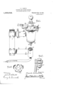
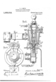
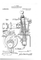
- Figure 1 is a perspective view of my invention.v Fig. 2, is an enlarged central vertical longitudinal section of the same in use, parts being broken'away. Fig. 3, is a similar view, the clamp being released and the hammer engine being swung away to its calking position.
- Fig. 1 is a top plan view of the machine, the parts being shown in the position shown in Fig. 2.
- Fig. '5' is a view similar to Fig. 4, the parts being in the position shown in Fig. 3.
- Fig, 6, is a detail perspective view ofthe retainer that holds the rivet set-or die in place on the engine.
- Fig. 7, is a detail sectiontshowing one of the pivots for the clamping device.
- 11 designates a pair of plates which are bolted together by two sets of bolts 2 and between which the lower and upper pipes 3-.4 respectively are clamped.
- the block 9 forms a die holder and is apertured at 10 to receive the'shank of the die 11 whose head is cupped at 12 to conform to the'contour of the head of the rivet R which joins the plates of the boiler-B.
- the casing 13 designates a retaining hammer casing of frusto-conical form, the end of lesser diameter being at the bottom and provided with .a concaved seat 16.
- the casing 13- also has a tubular-extension 14 to enter the pipe 4 towhich it is pinned at15, asindica-ted.
- the casing 13 at its upper end has a bracketlike extension 17 to receive the pivot bolts Patented Sept. 12, 1911.
- the clamp which serves to retain the engine 24 in its central position during the upsetting action on the rivet, is composed of a pair of half clamp members 19 each having a body 20 apertured to receive the pivots 18, the body 20 where the pivots 18 pass through being rounded and provided with toothed portions 21 to intermesh with one another so that the movement of one of the sections 19by its handle extension 22 will effect a similar movement in the other section 19 to open or close the clamping device according as the handle 22 is movedin one direction, or the other.
- the clamping device has its portion 19 upwardly projected and provided with a coniform seat 23 that cooperates with the correspondingly formed shoulder 35 of the hammer engine casing. 7
- the hammer engine 24 may be of any approved construction, preferably, however, that shown in the drawings, and the easing of the engine is provided at its lower end with a spherical'segment 25 that engages the concaved seat 16, the curvature of the seat 16 and the corresponding face of the segment 25 being struck from the center of curvature R of the upset head of the rivet R, or in other words, being curved on the same center as is the cup 33 of the die 30 that forms said rivet head.
- the casing of the hammer engine is also provided at its lower end with an extension'26 having an annular groove 27 to receive the upper fingers of the gripper 28 whose lower fingers 29 enter the groove 31 on the head of the die 30.
- the die 30 has a shank 32 to project into the engine 24 and be impacted by its hammer piston, as clearly shown in the drawings, and as is usual in the art.
- the die 30 has its end face surrounding the cup portion 33, of coniform or beveled formation as at 34 for a purpose'hereinafter more clearly understood.
- the engine casing 24 is adapted to swing on the center R when the clamp 19 is released to lie in engagement with the inner wall of the casing 13, as shown in Fig. 3 of the drawings, so that the casing maybe rotated on the center Bf in agyratory manner to eflect the 'calking action, as will be better understoodlater.
- the casing 24 is adapted to be moved by a handle 36 secured in itsupper end.
- the device is adapted to be suspended from an overhead crane, not shown, through the medium of an adjustable clamp 37 on the pipe 4, the clamp 37 being shift-able along the pipe to the center of balance of the device as a whole, so as to maintain the pipes 3-4 as nearly horizontal'as practicable.
- the working agent which may be compressed air, steam or other suitable motive fluid, is admitted to the engine 24 through a feed pipe 38, as clearly shown in the drawings.
- the clamp sections 19 are closed onto the casing 24 and when working agentis admitted to-the pipe 38 the hammer 40 is set into reciprocation in the usual manner to impact the'fdie member 30 and cause it to upset the end of the rivet R until the parts assume the position shown in Fig. 2 of the drawings, after which the clamp 19 is released, the casing 24 is turned until it lies in contact with the "inner wall of the casing after which a rotary motion is imparted to the engine 24 while it lies in contact with the casing 13, as shown in Fig. 3 of the drawings, thereby calking the rivet and insuring a tight joint.
- a support including a pair of arms, an anvil mechanism carried by one of said arms and an upsetting and calking mechanism carried by the other arm, each of said mechanisms including rivet engaging dies, said upsetting and calking mechanism also including a hammer engine retaining casing, a hammer engine movably mounted in said casing,'means for rigidly holding said en-- gine in the axial line of said casing at times,
- said engine having a die receiving portion for one of said dies.
- a support including a pair of arms, an anvil.
- each of said mechanisms including rivetengaging dies
- said upsetting and calking mechanism also including a hammer engine retaining casing, a hammer engine gyrat-ionally movable in said casing, releasable means for rigidly holding said engine in the axial line of said casing, said engine having a die receiving portion for one of said dies.
- a support a hollow casing having an internal chamber of frusto-conical form and provided at one end with-a concaved seat
- a releasable clamping mechanism mounted on the other end of said. hollow casing.
- a hammer engine mounted within said hollow casing and having a portion to be gripped by said clamping mechanism, said hammer” engine also having a portion provided with a convexed surface to engage said concaved seat whereby said engine will he rigidly held in position in said hollow casing when said clamping mechanism is in engagement with said engine, said engine including, a die receiving portion. and means for retaining a die in said die receiving portion.
- a support a hollow casing having an internal chamber of frusto-conical form and provided at one end with a concaved seat, a releasable clamping mechanism mounted on the other end of said hollow casing, a hammer engine mount'ed within said hollow casing and having a portion to be gripped by said clamping mechanism, said hammer engine also having a portion provided with a convexed surface to engage said concaved seat-whereby 'saidengine will be rigidly held in position in said hollow casing when said clamping mechanism is in engagement with said engine, said engine including a die receiving portion, means for retaining a die in said.
- a support having a pair of arms, a cup like member carried by one arm, a block mounted in said cup like member, means for admitting, fluid under pressure to said cup-like member to force said block upwardly, said block having a die receiving aperture, a die held in said aperture, a hammer retaining casing carried by said other arm, said hammer retaining casing being hollow and having the inner wall of frusto-conical form, a hammer engine mounted in said retaining casing, means carried by said retaining casing for releasably engaging said engine to hold it in a definite position, said engine having a die receiving portion and a die held in said die receiving portion to cooperate with said first mentioned die.
- a support having a pair'of arms, a cup like member carried by the one arm, a block mounted in said cup-like member, means for admitting fluid under pressure to said cuplike member to force said block upwardly, said block having a die receiving aperture, a die held in said aperture, a hammer retaining casing carried by said other arm, said hammer retaining casing bein hollow and having the inner wall of rusto-conical form, a hammer engine mounted in said retaining casing, means carried by said retaining casing for releasably engaging said engine to hold it in a definite position, said engine having a die receiving portion and a die held in said die receiving portion to cooperate with said first mentioned die, and means for releasing said engine holding means to permit said engine to be swung over into engagement with the inner wall of said retaining casing.
- a support having a pair of arms, a cup-like member carried by the one arm, a block mounted in said cup-like member, means for admitting fluld under pressure to sald cuplike member to force said block upwardly,
- a support having a pair of arms, a cuplike member carried by the one arm, a
- said engine having a die receiving portion, a die held in said die receiving portion to cooperate with said first mentioned die, an engine clamping device including a pair of half clamp sections pivoted to said retaining casing and having interengaged gear portions whereby when one of said sections is moved on its pivot the other section will be correspondingly moved.
Landscapes
- Engineering & Computer Science (AREA)
- Mechanical Engineering (AREA)
- Percussive Tools And Related Accessories (AREA)
Description
C. J. $MITH.
RIVETING AND GALKING MACHINE.
APPLICATION FILED 001. 19, 1910.
11,003,012. Patented Sept. 12,1911.
3 SHEETS-SHEET 1.
vjnvcnfoz lvttttaowe t 6' Lav/17:1 (7.15 110% y a (9 t G. J. SMITH.
RIVETING AND OALKING MACHINE.
APPLICATION FILED 001?. 19,1910.
1,003,012. Patented Sept. 12,1911.
3 SHEETS-BHEET 2.
38 To W1" m [ll/Au ml /ll I To oomp'r agy g wdr fupp'ly R 1 c. J-.' 311111311 RIVETING AND OALKING MACHINE. APPLICATION FILED OCT. 19, 1910 1,003,012. Patented Sept. 12,1911.
3 SHEETS-SHEET 3.
To mm UNITED STATES PATENT OFFICE. v
GLARKJ'. SIIIITH; OTTUMWA, IOWA, ASSIGNOR TO THE HABDSOCG WONDER DRILL COMPANY, OF O'JPIIJ'JllIWA, IOWA.
nrvnrmc AND cnmrrne MACHINE.
- Tocll whom it may concern:
Be it known that I, CLARK J. SMITH, re siding atOttumwa, in the county of Wapello and State of Iowa, have invented a 'new and. Improved Riveting and Calking Machine, of which the following is a specification.
My invention is an improved machine that is particularly designed for use in riveting and calking boiler plates and the like, and which generically includes a supporting frame composed of an arm that may be "projected into the boiler and carries an anvil die and its holder; a second armthat is connected to the, first arm to lie parallel thereto, the second arm carrying a retaining hammer casing of frusto-conical form to, which the riveting hammer en ine projects, a clamp provided for holding the ing the rivetupsetting operation, -which clamp may be moved to release the engine *so it may be given a gyratory movement in the casing to cause the rivet set or die to be griven to eflect a tight calking of the rivet ead. In its more subordinate nature, the in- .vention includes those novel details of construction, combination and arrangement of imparts, all of which will be first fully described, then be specifically pointed out in the appended claims, and illustrated in the accompanying drawings, in which:
Figure 1, is a perspective view of my invention.v Fig. 2, is an enlarged central vertical longitudinal section of the same in use, parts being broken'away. Fig. 3, is a similar view, the clamp being released and the hammer engine being swung away to its calking position. Fig. 1, is a top plan view of the machine, the parts being shown in the position shown in Fig. 2. Fig. '5', is a view similar to Fig. 4, the parts being in the position shown in Fig. 3. Fig, 6, is a detail perspective view ofthe retainer that holds the rivet set-or die in place on the engine. Fig. 7, is a detail sectiontshowing one of the pivots for the clamping device.
Referring now to the accompanying drawings, in which like letters and numerals of reference indicate like parts in all of the figures, 11 designates a pair of plates which are bolted together by two sets of bolts 2 and between which the lower and upper pipes 3-.4 respectively are clamped.
Specification of Letters Patent.
. Applioation-filedOctobcr 19, 1940.-- Serial Il'o. 587,888.
engine centrally in the retaining casing dur-.
5 designates a tubular casing \i'w in which a block 9 is mounted for longitudinal movement under. the influence of pneumatic pressure, or its equivalent, the casing'or cup 5 having an extension 6 to enter one end of the pipe 3 and it is riveted .to' such pipe by rivets 7 as'shown in the drawings.
8 designates the inlet to the cup 5' through which the working agent that forces the block upwardly, is admitted.
The block 9 forms a die holder and is apertured at 10 to receive the'shank of the die 11 whose head is cupped at 12 to conform to the'contour of the head of the rivet R which joins the plates of the boiler-B.
13 designates a retaining hammer casing of frusto-conical form, the end of lesser diameter being at the bottom and provided with .a concaved seat 16. The casing 13- also has a tubular-extension 14 to enter the pipe 4 towhich it is pinned at15, asindica-ted. .The casing 13 at its upper end has a bracketlike extension 17 to receive the pivot bolts Patented Sept. 12, 1911.
18 on which the clamp sections 19 are mounted.
The clamp which serves to retain the engine 24 in its central position during the upsetting action on the rivet, is composed of a pair of half clamp members 19 each having a body 20 apertured to receive the pivots 18, the body 20 where the pivots 18 pass through being rounded and provided with toothed portions 21 to intermesh with one another so that the movement of one of the sections 19by its handle extension 22 will effect a similar movement in the other section 19 to open or close the clamping device according as the handle 22 is movedin one direction, or the other.
The clamping device has its portion 19 upwardly projected and provided with a coniform seat 23 that cooperates with the correspondingly formed shoulder 35 of the hammer engine casing. 7
The hammer engine 24 may be of any approved construction, preferably, however, that shown in the drawings, and the easing of the engine is provided at its lower end with a spherical'segment 25 that engages the concaved seat 16, the curvature of the seat 16 and the corresponding face of the segment 25 being struck from the center of curvature R of the upset head of the rivet R, or in other words, being curved on the same center as is the cup 33 of the die 30 that forms said rivet head. The casing of the hammer engine is also provided at its lower end with an extension'26 having an annular groove 27 to receive the upper fingers of the gripper 28 whose lower fingers 29 enter the groove 31 on the head of the die 30. The die 30 has a shank 32 to project into the engine 24 and be impacted by its hammer piston, as clearly shown in the drawings, and as is usual in the art. The die 30 has its end face surrounding the cup portion 33, of coniform or beveled formation as at 34 for a purpose'hereinafter more clearly understood.
The engine casing 24 is adapted to swing on the center R when the clamp 19 is released to lie in engagement with the inner wall of the casing 13, as shown in Fig. 3 of the drawings, so that the casing maybe rotated on the center Bf in agyratory manner to eflect the 'calking action, as will be better understoodlater. The casing 24 is adapted to be moved by a handle 36 secured in itsupper end.
The device is adapted to be suspended from an overhead crane, not shown, through the medium of an adjustable clamp 37 on the pipe 4, the clamp 37 being shift-able along the pipe to the center of balance of the device as a whole, so as to maintain the pipes 3-4 as nearly horizontal'as practicable. a
The working agent, which may be compressed air, steam or other suitable motive fluid, is admitted to the engine 24 through a feed pipe 38, as clearly shown in the drawings.
Inoperation the pipe 3 with its carried parts is projected into the boiler to engage the head of the rivet R, as shown in Fig. 2, while the die 30 is brought into engagement with the end of the rivet R to be upset, it being understood that the plunger block 9 permits bringing the parts in position, and it is itself held in place by the working agent that enters through the pipe 39.
The clamp sections 19 are closed onto the casing 24 and when working agentis admitted to-the pipe 38 the hammer 40 is set into reciprocation in the usual manner to impact the'fdie member 30 and cause it to upset the end of the rivet R until the parts assume the position shown in Fig. 2 of the drawings, after which the clamp 19 is released, the casing 24 is turned until it lies in contact with the "inner wall of the casing after which a rotary motion is imparted to the engine 24 while it lies in contact with the casing 13, as shown in Fig. 3 of the drawings, thereby calking the rivet and insuring a tight joint.
From the foregoing description taken in connection with the accompanying drawings, it is thought the complete construction, operation and advantages of my invention will bereadily understood by those skilled in the art to which the invention appertains.
What I claim is:
1. In an apparatus of the class described, a support including a pair of arms, an anvil mechanism carried by one of said arms and an upsetting and calking mechanism carried by the other arm, each of said mechanisms including rivet engaging dies, said upsetting and calking mechanism also including a hammer engine retaining casing, a hammer engine movably mounted in said casing,'means for rigidly holding said en-- gine in the axial line of said casing at times,
.said engine having a die receiving portion for one of said dies.
2. In an apparatus of the class described,
a support including a pair of arms, an anvil.
mechanism carried by one of said arms and an upsetting and calking mechanism carried by the other arm, each of said mechanisms including rivetengaging dies, said upsetting and calking mechanism also including a hammer engine retaining casing, a hammer engine gyrat-ionally movable in said casing, releasable means for rigidly holding said engine in the axial line of said casing, said engine having a die receiving portion for one of said dies.
3. In an apparatus of the class described, a support, a hollow casing having an internal chamber of frusto-conical form and provided at one end with-a concaved seat,"
a releasable clamping mechanism mounted on the other end of said. hollow casing. a hammer engine mounted within said hollow casing and having a portion to be gripped by said clamping mechanism, said hammer" engine also having a portion provided with a convexed surface to engage said concaved seat whereby said engine will he rigidly held in position in said hollow casing when said clamping mechanism is in engagement with said engine, said engine including, a die receiving portion. and means for retaining a die in said die receiving portion.
4. In an apparatus of the class described, a support, a hollow casing having an internal chamber of frusto-conical form and provided at one end with a concaved seat, a releasable clamping mechanism mounted on the other end of said hollow casing, a hammer engine mount'ed within said hollow casing and having a portion to be gripped by said clamping mechanism, said hammer engine also having a portion provided with a convexed surface to engage said concaved seat-whereby 'saidengine will be rigidly held in position in said hollow casing when said clamping mechanism is in engagement with said engine, said engine including a die receiving portion, means for retaining a die in said. die receiving portion, a die in said die receiving portion retained by said retaining means, said die having a rivet engaging recess in its outer end, and said concaved seat being curved on an are having as its center the center of curvature of said die recess.
5. In an apparatus of the class described,
a support having a pair of arms, a cup like member carried by one arm, a block mounted in said cup like member, means for admitting, fluid under pressure to said cup-like member to force said block upwardly, said block having a die receiving aperture, a die held in said aperture, a hammer retaining casing carried by said other arm, said hammer retaining casing being hollow and having the inner wall of frusto-conical form, a hammer engine mounted in said retaining casing, means carried by said retaining casing for releasably engaging said engine to hold it in a definite position, said engine having a die receiving portion and a die held in said die receiving portion to cooperate with said first mentioned die.
6. In an apparatus of the class described,
. a support having a pair'of arms, a cup like member carried by the one arm, a block mounted in said cup-like member, means for admitting fluid under pressure to said cuplike member to force said block upwardly, said block having a die receiving aperture, a die held in said aperture, a hammer retaining casing carried by said other arm, said hammer retaining casing bein hollow and having the inner wall of rusto-conical form, a hammer engine mounted in said retaining casing, means carried by said retaining casing for releasably engaging said engine to hold it in a definite position, said engine having a die receiving portion and a die held in said die receiving portion to cooperate with said first mentioned die, and means for releasing said engine holding means to permit said engine to be swung over into engagement with the inner wall of said retaining casing.
7. In an apparatus of the class described, a support having a pair of arms, a cup-like member carried by the one arm, a block mounted in said cup-like member, means for admitting fluld under pressure to sald cuplike member to force said block upwardly,
casing to engage a part of said engine at one end, and a releasable clamping device on said retaining casing to engage said engine near its other end.
8. In an apparatus of the kind described, a support having a pair of arms, a cuplike member carried by the one arm, a
block mounted in said cup-like member, means for admitting fluid under pressure to said cup-like member to force said block upwardly, said block having a die receiving aperture, a die held in said aperture, a hammer retaining casing carried by said other arm, said-hammer retaining casing being hollow and having an inner wall of frustoconical form, a hammer engine mountedin said retaining casing, means carried by said retainin casing for releasably engaging said engine to hold it in a definite position,
said engine having a die receiving portion, a die held in said die receiving portion to cooperate with said first mentioned die, an engine clamping device including a pair of half clamp sections pivoted to said retaining casing and having interengaged gear portions whereby when one of said sections is moved on its pivot the other section will be correspondingly moved.
CLARK J. SMITH.
Witnesses:
GERTRUDE S. ORR, J. F. ADAMS.
Priority Applications (1)
| Application Number | Priority Date | Filing Date | Title |
|---|---|---|---|
| US58788810A US1003012A (en) | 1910-10-19 | 1910-10-19 | Riveting and calking machine. |
Applications Claiming Priority (1)
| Application Number | Priority Date | Filing Date | Title |
|---|---|---|---|
| US58788810A US1003012A (en) | 1910-10-19 | 1910-10-19 | Riveting and calking machine. |
Publications (1)
| Publication Number | Publication Date |
|---|---|
| US1003012A true US1003012A (en) | 1911-09-12 |
Family
ID=3071331
Family Applications (1)
| Application Number | Title | Priority Date | Filing Date |
|---|---|---|---|
| US58788810A Expired - Lifetime US1003012A (en) | 1910-10-19 | 1910-10-19 | Riveting and calking machine. |
Country Status (1)
| Country | Link |
|---|---|
| US (1) | US1003012A (en) |
Cited By (1)
| Publication number | Priority date | Publication date | Assignee | Title |
|---|---|---|---|---|
| US2904786A (en) * | 1955-03-10 | 1959-09-22 | Melpar Inc | Stapling machines |
-
1910
- 1910-10-19 US US58788810A patent/US1003012A/en not_active Expired - Lifetime
Cited By (1)
| Publication number | Priority date | Publication date | Assignee | Title |
|---|---|---|---|---|
| US2904786A (en) * | 1955-03-10 | 1959-09-22 | Melpar Inc | Stapling machines |
Similar Documents
| Publication | Publication Date | Title |
|---|---|---|
| US1476756A (en) | Device for producing rivet connections | |
| US1592017A (en) | Pliers | |
| US2539040A (en) | Pivoted hand tool for body and fender straightening | |
| US2384690A (en) | Collet type pulling head | |
| US950496A (en) | Stapling-machine. | |
| US2179900A (en) | Rivet setting machine | |
| US1444909A (en) | Riveting press | |
| US1669116A (en) | Peening tool | |
| US1382625A (en) | Automatic release mechanism for heading and forging machines | |
| US1424671A (en) | Metal-working machine | |
| US1430292A (en) | Work clamping and cushioning attachment for pneumatic hammers | |
| US1402901A (en) | Riveting machine | |
| US1166636A (en) | Shell-crimper. | |
| US1470077A (en) | Plate-valve ttstloader | |
| US1238785A (en) | Riveting-machine. | |
| US1281091A (en) | Riveting apparatus. | |
| US1886241A (en) | Pneumatic rivet squeezer | |
| US1027289A (en) | Riveting-machine. | |
| US818843A (en) | Tube expanding and beading tool. | |
| US2121817A (en) | Punch mechanism | |
| US1547281A (en) | Riveting machine | |
| US2384175A (en) | Squeeze riveter | |
| US1296139A (en) | Boiler-riveting machine. | |
| US1385820A (en) | Pneumatic rivet-passing apparatus | |
| US1388437A (en) | of denver |