US10027273B2 - Plunger and puck mounting system for photovoltaic panels - Google Patents
Plunger and puck mounting system for photovoltaic panels Download PDFInfo
- Publication number
- US10027273B2 US10027273B2 US14/701,475 US201514701475A US10027273B2 US 10027273 B2 US10027273 B2 US 10027273B2 US 201514701475 A US201514701475 A US 201514701475A US 10027273 B2 US10027273 B2 US 10027273B2
- Authority
- US
- United States
- Prior art keywords
- base portion
- plunger
- foot
- latch
- assembly
- Prior art date
- Legal status (The legal status is an assumption and is not a legal conclusion. Google has not performed a legal analysis and makes no representation as to the accuracy of the status listed.)
- Active, expires
Links
Images


Classifications
-
- H—ELECTRICITY
- H02—GENERATION; CONVERSION OR DISTRIBUTION OF ELECTRIC POWER
- H02S—GENERATION OF ELECTRIC POWER BY CONVERSION OF INFRARED RADIATION, VISIBLE LIGHT OR ULTRAVIOLET LIGHT, e.g. USING PHOTOVOLTAIC [PV] MODULES
- H02S20/00—Supporting structures for PV modules
- H02S20/20—Supporting structures directly fixed to an immovable object
- H02S20/22—Supporting structures directly fixed to an immovable object specially adapted for buildings
- H02S20/23—Supporting structures directly fixed to an immovable object specially adapted for buildings specially adapted for roof structures
-
- F24J2/5254—
-
- F—MECHANICAL ENGINEERING; LIGHTING; HEATING; WEAPONS; BLASTING
- F24—HEATING; RANGES; VENTILATING
- F24S—SOLAR HEAT COLLECTORS; SOLAR HEAT SYSTEMS
- F24S25/00—Arrangement of stationary mountings or supports for solar heat collector modules
- F24S25/60—Fixation means, e.g. fasteners, specially adapted for supporting solar heat collector modules
- F24S25/63—Fixation means, e.g. fasteners, specially adapted for supporting solar heat collector modules for fixing modules or their peripheral frames to supporting elements
- F24S25/632—Side connectors; Base connectors
-
- Y—GENERAL TAGGING OF NEW TECHNOLOGICAL DEVELOPMENTS; GENERAL TAGGING OF CROSS-SECTIONAL TECHNOLOGIES SPANNING OVER SEVERAL SECTIONS OF THE IPC; TECHNICAL SUBJECTS COVERED BY FORMER USPC CROSS-REFERENCE ART COLLECTIONS [XRACs] AND DIGESTS
- Y02—TECHNOLOGIES OR APPLICATIONS FOR MITIGATION OR ADAPTATION AGAINST CLIMATE CHANGE
- Y02B—CLIMATE CHANGE MITIGATION TECHNOLOGIES RELATED TO BUILDINGS, e.g. HOUSING, HOUSE APPLIANCES OR RELATED END-USER APPLICATIONS
- Y02B10/00—Integration of renewable energy sources in buildings
- Y02B10/10—Photovoltaic [PV]
-
- Y02B10/12—
-
- Y—GENERAL TAGGING OF NEW TECHNOLOGICAL DEVELOPMENTS; GENERAL TAGGING OF CROSS-SECTIONAL TECHNOLOGIES SPANNING OVER SEVERAL SECTIONS OF THE IPC; TECHNICAL SUBJECTS COVERED BY FORMER USPC CROSS-REFERENCE ART COLLECTIONS [XRACs] AND DIGESTS
- Y02—TECHNOLOGIES OR APPLICATIONS FOR MITIGATION OR ADAPTATION AGAINST CLIMATE CHANGE
- Y02E—REDUCTION OF GREENHOUSE GAS [GHG] EMISSIONS, RELATED TO ENERGY GENERATION, TRANSMISSION OR DISTRIBUTION
- Y02E10/00—Energy generation through renewable energy sources
- Y02E10/40—Solar thermal energy, e.g. solar towers
- Y02E10/47—Mountings or tracking
-
- Y—GENERAL TAGGING OF NEW TECHNOLOGICAL DEVELOPMENTS; GENERAL TAGGING OF CROSS-SECTIONAL TECHNOLOGIES SPANNING OVER SEVERAL SECTIONS OF THE IPC; TECHNICAL SUBJECTS COVERED BY FORMER USPC CROSS-REFERENCE ART COLLECTIONS [XRACs] AND DIGESTS
- Y02—TECHNOLOGIES OR APPLICATIONS FOR MITIGATION OR ADAPTATION AGAINST CLIMATE CHANGE
- Y02E—REDUCTION OF GREENHOUSE GAS [GHG] EMISSIONS, RELATED TO ENERGY GENERATION, TRANSMISSION OR DISTRIBUTION
- Y02E10/00—Energy generation through renewable energy sources
- Y02E10/50—Photovoltaic [PV] energy
Definitions
- PV photovoltaic
- the system can include a base portion, a foot portion for supporting a PV module frame mounting component, and a plunger.
- the plunger can pass through the foot portion and selectively couple to the base portion. Application of a downward force on one end of the plunger may compress the plunger towards the base portion to selectively lock the foot portion to the base portion.
- the plunger may include an elongated shaft passing through the foot portion.
- the plunger can selectively couple to the base portion via a latch positioned between the plunger and base portion.
- the latch can include first and second flexible flanges adapted to extend into fixed connection with the base portion.
- the plunger can include first and second extensions that respectively lock the first and second flexible flanges of the latch into the base portion.
- the plunger can include tabs on the shaft that lock the shaft with the latch during compression of the plunger to prevent further movement of the plunger.
- the system can include a base portion for mounting to a roof.
- a foot can be provided and has an elongated body adapted to connect to at least one PV module frame mounting component.
- the system can include a latch between the foot and the base portion.
- the latch can have first and second flexible flanges adapted to extend into fixed connection with the base portion.
- a plunger can be provided and have first and second extensions. The plunger can be located between the latch and the base portion and moveable from a first position to a second position. In a first position of the plunger, the first and second flexible flanges of the latch are not in fixed connection with the base portion. In the second position of the plunger, the first and second extensions of the plunger respectively apply forces to the first and second flexible flanges such that the first and second flexible flanges are placed into fixed connection with the base portion.
- the base portion can have a lip for the first and second flexible flanges to fixedly connect to.
- the base portion can be a circular puck configured for connection to a lag bolt.
- a bottom portion of the base portion can be configured to mount to a roof flashing.
- the plunger can have an elongated shaft that extends upwardly through a passage in the latch and a slot within the foot.
- the shaft can have a plurality of tabs that are configured to secure to a portion of the latch.
- the shaft can be a rectangular tube.
- the shaft can extend downwardly to a pair of flanges that further extend to a planar base portion.
- the first extension can be one end of the planar base portion, and wherein the second extension can be another end of the planar base portion.
- the first and second extensions can be curved to match a lip of the base portion.
- the planar base portion can include a passage for clearing the head of a lag bolt.
- the latch can have a planar portion horizontally arranged to slide within the foot in the first position of the plunger.
- the planar portion can have a first end and a second end, such that the first flexible flange extends downwardly from the first end and the second flexible flange extends downwardly from the second end.
- the first and second flexible flanges in the first position of the plunger can be shaped with an inward bias towards one another.
- the first and second flexible flanges in the first position of the plunger can be placed in a tensioned state forced against the inward bias by the first and second extensions of the plunger.
- the first extension can push the first flexible flange away from the second flexible flange and into a complimentary first portion of the base portion
- the second extension can push the second flexible flange away from the first flexible flange and into a complimentary second portion of the base portion
- the elongated body of the foot can be formed as a U-shaped extrusion that is elongated along a first direction and can have channels elongated along the first direction for holding the latch.
- the elongated body of the foot can include at least one elongated slot that a shaft of the plunger can be laterally positioned within.
- the elongated body of the foot can include at least one mounting hole for mounting to the at least one PV module frame mounting component.
- the system can include a lag bolt for mounting the base portion to a roof structure.
- the system can include a washer mounted between the lag bolt and the plunger, with the washer providing a raised surface for the plunger.
- the system can include a cap arranged above the foot and configured to transfer force to the plunger for changing from the first position of the plunger to the second position of the plunger.
- PV photovoltaic
- Many embodiments of the invention are directed to a photovoltaic (PV) mounting hardware support system having a base portion assembly for mounting to a structure.
- a foot assembly can be detachably coupled to the base portion assembly.
- the foot assembly can include a latch configured to fixedly secure to the base portion assembly without any bolts sufficiently to support at least one PV module frame.
- the base portion assembly can include at least a puck.
- the base portion assembly can further include a lag bolt for securing the base portion assembly to a roof structure.
- the base portion assembly can further include a flashing configured to mount between the puck and the roof structure.
- the latch can include a pair of flanges
- the foot assembly further can include a plunger for pushing the pair of flanges into the puck.
- downward movement of the plunger fixedly secures the foot assembly to the base portion assembly.
- the foot assembly can include a cap coupled to the plunger, such that downward force placed upon the cap causes the downward movement of the plunger.
- the foot assembly can include a PV module frame mounting component.
- the foot assembly can include a plurality of preassembled components and is provided with the base portion assembly within a kit.
- FIG. 1A shows an exploded perspective view of an exemplary PV mounting system, according to an embodiment of the invention.
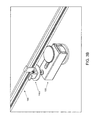
- FIG. 1B shows an assembled perspective view of the system of FIG. 1A .
- FIGS. 2A and 2B show cross-sectional views of the system of FIG. 1A .
- FIGS. 3A-3D show the system of FIG. 1A in use, according to various embodiments of the invention.
- Embodiments of the invention are generally directed towards a system for mounting a PV panel to a support structure such as a roof surface.
- the system can include a base portion assembly and a foot assembly for supporting a PV panel.
- the foot assembly may include a moveable latch that when moved into a fixed position with the base portion assembly, provides a boltless system for rigidly fixing the foot assembly to the base portion assembly in a sufficient manner to permanently support the weight of one or more PV panels.
- a moveable latch that when moved into a fixed position with the base portion assembly, provides a boltless system for rigidly fixing the foot assembly to the base portion assembly in a sufficient manner to permanently support the weight of one or more PV panels.
- FIGS. 1A and 1B respectively show assembled and exploded views of an exemplary system 100 for mounting a PV panel to a structure, such as a roof.
- the system 100 includes a base portion 102 , which here is formed as a puck having an inner lip 104 .
- the base portion 102 has a lower surface that is configured to directly or indirectly mount to a structure, and can include one or more passages for mounting the base portion 102 via a lag bolt 106 and washer 108 .
- the washer 108 is not used or functionally integrated into the shape of the base portion 102 as a raised surface.
- the base portion is not limited to puck-like design, for example, the inner lip 104 may be integrated into a flashing or specialized shingle to provide the functionality of the base portion 102 in a different form.
- a plunger 110 having a shaft 112 .
- the shaft 112 has a rectangular cross-section, but is not limited to such a shape, and may for example have a circular or hexagonal cross-section.
- the shaft 112 includes one or more tabs 114 that extend in lateral directions.
- the shaft 112 leads to a planar base portion 116 by way of a pair of flanges 118 .
- the planar base portion 116 has first and second extensions 119 leading laterally away from the shaft 112 , as well as a passage 120 to provide clearance for the head of the lag bolt 106 .
- the first and second extensions 119 can be curved to match the profile of the lip 104 of the base portion 102 and/or the flanges of the latch described below.
- the system 100 also includes a latch 122 .
- the latch 122 has an uppermost planar portion 124 and a pair of first and second flexible flanges 126 that lead downwardly from ends of the planar portion 124 .
- the first and second flexible flanges 126 include edges 128 that are complimentary shaped (e.g. rounded) to fit into the inner lip 104 of the base portion 102 .
- the first and second flexible flanges 126 are biased inwardly such that the edges 128 have a smaller diameter than the inner diameter of the inner lip 104 .
- the planar portion 124 also includes a passage (not shown in these views) for allowing the shaft 112 of the plunger 110 to pass through.
- a foot 130 which is configured as an elongated U-shaped body having multiple walls.
- the planar portion 124 of the latch 122 is configured to slide into elongated channels 132 on an underside of the foot 130 .
- the foot 130 includes a passage, which can be an elongated slot 134 for allowing the shaft 112 of the plunger 110 to pass through.
- the foot 130 also includes one or more passages 136 for enabling connection to at least one PV module frame mounting component.
- An optional cap 138 is positioned on top of the foot 130 .
- the cap 138 includes a cap shaft 140 that is configured to mate with the shaft 112 of the plunger 110 .
- FIGS. 2A and 2B show cross-sectional views of the system 100 .
- the base portion 102 , lag bolt 106 , and washer 108 are typically installed first as a base portion assembly. This is performed by drilling a suitable sized hole into a structure and then bolting the lag bolt 106 into the drilled hole over the washer 108 and base portion 102 .
- the cap 138 , foot 130 , latch 122 , and plunger 110 can be preassembled as a foot assembly shown at FIG. 2A .
- the planar portion 124 of the latch 122 is slid into the channels 132 of the foot 130 .
- the plunger 110 is then inserted within the latch 122 such that the first and second extensions 119 fit within the first and second flexible flanges 126 and so that the shaft 112 extends upwardly through the passage of the latch 122 and the channel 134 of the foot 130 .
- the cap 138 is then attached to the shaft 112 .
- the foot assembly is preassembled with its requisite components and provided with the components of the base portion assembly as a complete installation kit. Hence, the installer does not need to assemble the foot assembly in the field.
- the foot assembly is placed onto the installed base portion assembly as shown at FIG. 2A , such that the edges 128 of the first and second flexible flanges 126 are placed within the lip 104 of the base portion 102 and such that the plunger 110 remains in an elevated first position.
- the elongated slot 134 of the foot 130 allows for flexibility in placing the foot with respect to the base portion 102 .
- the first and second flexible flanges 126 are not in fixed connection with the lip 104 of the base portion 102 .
- Downward force is then applied to the cap 138 , for example by stepping on it or by using a mallet.
- This causes the plunger 110 to travel down to a second position such that the planar base portion 116 meets the washer 108 .
- the first and second extensions 119 expand the first and second flexible flanges 126 outwardly.
- the edges 128 of the first and second flexible flanges 126 are forcibly wedged into the lip 104 of the base portion 102 .
- the first and second extensions 119 of the plunger 110 respectively apply forces to the first and second flexible flanges 126 such that the first and second flexible flanges 126 are placed into fixed connection with the base portion 102 .
- the tabs 114 of the shaft 112 extend laterally to prevent the bias of the first and second flexible flanges 126 from pushing the plunger 110 upward.
- the resulting configuration places the system 100 into a rigid configuration with respect to the structure the base portion 102 is affixed to, without requiring the use of any bolts aside from the lag bolt 106 .
- This un-bolted configuration allows the foot to have enough structural rigidity to support one or more PV panels.
- the system 100 is intended to be provide a permanent installation hard point for at least one PV module frame mounting component, and accordingly due to the tabs 114 , once placed into the position shown at FIG. 2B cannot be removed without damaging the system 100 .
- the tabs 114 of the plunger 110 can be accessed to release the plunger 110 and place the system 100 back into the form shown at FIG. 2A .
- the shaft 112 of the plunger 110 can be rotatable so that turning the shaft 112 causes the tabs 114 to be exposed to a wider portion of the passage within the latch 122 , and hence upon doing so lose contact with the latch 122 so that the plunger 110 can be pulled upward.
- the first and second flexible flanges 126 of the latch 122 can have openings to allow access of a tool to push the tabs 114 inward so that the plunger 110 can be pulled upward.
- the cap 138 is not used or is removable such that a tool can be used to access and release the tabs 114 through the shaft 112 of the plunger 110 .
- the cap 138 is not used or is removable to access the lag bolt 106 through the shaft 112 of the plunger 110 , for removal of the entire system 100 from a structure.
- FIG. 3A shows the system 100 with a PV module frame mounting component 142 attached to the foot 130 .
- the PV module frame mounting component 142 a is depicted simply as a threaded stud and frame mounting component, but many different types of PV module frame mounting components can be used instead.
- various embodiments of the invention may utilize a clamping style connector 142 b such as that shown in FIG. 3B .
- the PV module frame mounting component 142 a is preassembled to the foot 130 with the foot assembly shown at FIGS. 2A and 2B .
- FIG. 3C shows the system 100 assembled to a roof flashing 144 .
- the lower surface of the base portion 102 can be shaped to attach to a variety of different types of flashings such as the flat flashing shown.
- the roof flashing is preassembled to the base portion 102 with the base portion assembly shown at FIGS. 2A and 2B .
- the system 100 is connected to a PV module frame 146 via the PV module frame mounting component 144 . It should be appreciated, however, that in various embodiments, the base portion 102 may be mounted directly to a roof surface without use of flashing 144 .
- FIG. 3D shows a plurality of systems 100 used to connect an array of a PV module frames 146 , without the optional flashing.
Landscapes
- Engineering & Computer Science (AREA)
- Structural Engineering (AREA)
- Civil Engineering (AREA)
- Architecture (AREA)
- General Engineering & Computer Science (AREA)
- Mechanical Engineering (AREA)
- Sustainable Development (AREA)
- Combustion & Propulsion (AREA)
- Chemical & Material Sciences (AREA)
- Thermal Sciences (AREA)
- Sustainable Energy (AREA)
- Physics & Mathematics (AREA)
- Life Sciences & Earth Sciences (AREA)
- Roof Covering Using Slabs Or Stiff Sheets (AREA)
Abstract
Description
Claims (14)
Priority Applications (1)
| Application Number | Priority Date | Filing Date | Title |
|---|---|---|---|
| US14/701,475 US10027273B2 (en) | 2015-04-30 | 2015-04-30 | Plunger and puck mounting system for photovoltaic panels |
Applications Claiming Priority (1)
| Application Number | Priority Date | Filing Date | Title |
|---|---|---|---|
| US14/701,475 US10027273B2 (en) | 2015-04-30 | 2015-04-30 | Plunger and puck mounting system for photovoltaic panels |
Publications (2)
| Publication Number | Publication Date |
|---|---|
| US20160322929A1 US20160322929A1 (en) | 2016-11-03 |
| US10027273B2 true US10027273B2 (en) | 2018-07-17 |
Family
ID=57205241
Family Applications (1)
| Application Number | Title | Priority Date | Filing Date |
|---|---|---|---|
| US14/701,475 Active 2036-06-05 US10027273B2 (en) | 2015-04-30 | 2015-04-30 | Plunger and puck mounting system for photovoltaic panels |
Country Status (1)
| Country | Link |
|---|---|
| US (1) | US10027273B2 (en) |
Cited By (66)
| Publication number | Priority date | Publication date | Assignee | Title |
|---|---|---|---|---|
| USD862213S1 (en) * | 2018-06-20 | 2019-10-08 | Wild West Investments, LLC | Adapter for supporting an electronic device |
| US11177639B1 (en) | 2020-05-13 | 2021-11-16 | GAF Energy LLC | Electrical cable passthrough for photovoltaic systems |
| US11217715B2 (en) | 2020-04-30 | 2022-01-04 | GAF Energy LLC | Photovoltaic module frontsheet and backsheet |
| US11251744B1 (en) | 2020-06-04 | 2022-02-15 | GAF Energy LLC | Photovoltaic shingles and methods of installing same |
| US11283394B2 (en) | 2020-02-18 | 2022-03-22 | GAF Energy LLC | Photovoltaic module with textured superstrate providing shingle-mimicking appearance |
| US11309828B2 (en) | 2019-11-27 | 2022-04-19 | GAF Energy LLC | Roof integrated photovoltaic module with spacer |
| USD950481S1 (en) | 2020-10-02 | 2022-05-03 | GAF Energy LLC | Solar roofing system |
| USD950482S1 (en) | 2020-10-02 | 2022-05-03 | GAF Energy LLC | Solar roofing system |
| US11394344B2 (en) | 2020-08-11 | 2022-07-19 | GAF Energy LLC | Roof mounted photovoltaic system and method for wireless transfer of electrical energy |
| US11398795B2 (en) | 2019-12-20 | 2022-07-26 | GAF Energy LLC | Roof integrated photovoltaic system |
| US11431281B2 (en) | 2020-02-27 | 2022-08-30 | GAF Energy LLC | Photovoltaic module with light-scattering encapsulant providing shingle-mimicking appearance |
| US11444569B2 (en) | 2020-10-14 | 2022-09-13 | GAF Energy LLC | Mounting apparatus for photovoltaic modules |
| US20220290436A1 (en) * | 2019-09-04 | 2022-09-15 | J. Van Walraven Holding B.V. | Support foot for a free standing structure |
| US11454027B2 (en) | 2020-10-29 | 2022-09-27 | GAF Energy LLC | System of roofing and photovoltaic shingles and methods of installing same |
| US11459757B2 (en) | 2021-01-19 | 2022-10-04 | GAF Energy LLC | Watershedding features for roofing shingles |
| US11486144B2 (en) | 2020-11-12 | 2022-11-01 | GAF Energy LLC | Roofing shingles with handles |
| US11489482B2 (en) | 2020-01-22 | 2022-11-01 | GAF Energy LLC | Integrated photovoltaic roofing shingles, methods, systems, and kits thereof |
| US11496088B2 (en) | 2021-02-19 | 2022-11-08 | GAF Energy LLC | Photovoltaic module for a roof with continuous fiber tape |
| US11508861B1 (en) | 2021-06-02 | 2022-11-22 | GAF Energy LLC | Photovoltaic module with light-scattering encapsulant providing shingle-mimicking appearance |
| US11512480B1 (en) | 2021-07-16 | 2022-11-29 | GAF Energy LLC | Roof material storage bracket |
| US11527665B2 (en) | 2021-05-06 | 2022-12-13 | GAF Energy LLC | Photovoltaic module with transparent perimeter edges |
| US11545927B2 (en) | 2020-04-09 | 2023-01-03 | GAF Energy LLC | Three-dimensional laminate photovoltaic module |
| US11545928B2 (en) | 2020-10-13 | 2023-01-03 | GAF Energy LLC | Solar roofing system |
| US11572021B2 (en) | 2020-01-31 | 2023-02-07 | Wild West Investments, LLC | Vehicular mounted rail system |
| US11728759B2 (en) | 2021-09-01 | 2023-08-15 | GAF Energy LLC | Photovoltaic modules for commercial roofing |
| US11811361B1 (en) | 2022-12-14 | 2023-11-07 | GAF Energy LLC | Rapid shutdown device for photovoltaic modules |
| US11824486B2 (en) | 2022-01-20 | 2023-11-21 | GAF Energy LLC | Roofing shingles for mimicking the appearance of photovoltaic modules |
| US11824487B2 (en) | 2020-11-13 | 2023-11-21 | GAF Energy LLC | Photovoltaic module systems and methods |
| US11843067B2 (en) | 2020-07-22 | 2023-12-12 | GAF Energy LLC | Photovoltaic modules |
| US11870227B2 (en) | 2020-09-03 | 2024-01-09 | GAF Energy LLC | Building integrated photovoltaic system |
| US11894796B2 (en) | 2012-10-02 | 2024-02-06 | Bmic Llc | Roof integrated solar power system with top mounted electrical components and cables |
| US11961928B2 (en) | 2020-02-27 | 2024-04-16 | GAF Energy LLC | Photovoltaic module with light-scattering encapsulant providing shingle-mimicking appearance |
| US11984521B2 (en) | 2022-03-10 | 2024-05-14 | GAF Energy LLC | Combined encapsulant and backsheet for photovoltaic modules |
| US11996797B2 (en) | 2020-12-02 | 2024-05-28 | GAF Energy LLC | Step flaps for photovoltaic and roofing shingles |
| US12009782B1 (en) | 2023-04-04 | 2024-06-11 | GAF Energy LLC | Photovoltaic systems with wireways |
| US12009781B2 (en) | 2021-07-06 | 2024-06-11 | GAF Energy LLC | Jumper module for photovoltaic systems |
| US12013153B2 (en) | 2022-02-08 | 2024-06-18 | GAF Energy LLC | Building integrated photovoltaic system |
| US12015374B2 (en) | 2022-09-26 | 2024-06-18 | GAF Energy LLC | Photovoltaic modules integrated with building siding and fencing |
| US12031332B2 (en) | 2022-10-25 | 2024-07-09 | GAF Energy LLC | Roofing materials and related methods |
| US12034089B2 (en) | 2022-09-01 | 2024-07-09 | GAF Energy LLC | Anti-reflective photovoltaic shingles and related methods |
| US12051996B2 (en) | 2022-09-13 | 2024-07-30 | GAF Energy LLC | Sensing roofing system and method thereof |
| US12088241B2 (en) | 2020-09-14 | 2024-09-10 | Array Tech, Inc. | Spring clip for photovoltaic module mounting |
| US12095415B2 (en) | 2021-03-29 | 2024-09-17 | GAF Energy LLC | Electrical components for photovoltaic systems |
| US12115919B2 (en) | 2022-10-14 | 2024-10-15 | Yonder Fund Llc | Mounting system with anti-rotation features for supporting an electronic device |
| US12143064B2 (en) | 2022-09-29 | 2024-11-12 | GAF Energy LLC | Jumper module with sleeve |
| US12145348B2 (en) | 2022-08-24 | 2024-11-19 | GAF Energy LLC | System for forming a roofing membrane, and associated method |
| US12176849B2 (en) | 2023-02-23 | 2024-12-24 | GAF Energy LLC | Photovoltaic shingles with multi-module power electronics |
| US12199550B2 (en) | 2022-04-08 | 2025-01-14 | GAF Energy LLC | Low profile connector for solar roofing systems |
| US12209414B2 (en) | 2022-02-23 | 2025-01-28 | GAF Energy LLC | Roofing shingle and method of manufacturing same |
| US12231075B2 (en) | 2022-10-27 | 2025-02-18 | GAF Energy LLC | Building integrated photovoltaic systems |
| US12237809B2 (en) | 2022-06-06 | 2025-02-25 | GAF Energy LLC | Active component indicators for photovoltaic systems |
| US12316268B2 (en) | 2023-10-26 | 2025-05-27 | GAF Energy LLC | Roofing systems with water ingress protection |
| US12325996B2 (en) | 2022-07-15 | 2025-06-10 | GAF Energy LLC | Solar roofing system with fiber composite roofing shingles |
| US12355390B1 (en) | 2023-02-03 | 2025-07-08 | GAF Energy LLC | Solar shingle and associated roofing system and method |
| US12413183B2 (en) | 2022-11-15 | 2025-09-09 | GAF Energy LLC | Electrical cable passthrough for photovoltaic systems |
| US12414385B2 (en) | 2022-08-29 | 2025-09-09 | GAF Energy LLC | Photovoltaic modules with offset layers |
| US12413174B2 (en) | 2023-02-21 | 2025-09-09 | GAF Energy LLC | Roofing system including photovoltaic module wireway cover, and associated method |
| US12413177B2 (en) | 2023-08-31 | 2025-09-09 | GAF Energy LLC | Photovoltaic modules and roofing shingles with nail zones |
| US12438495B2 (en) | 2023-12-05 | 2025-10-07 | GAF Energy LLC | Roofing system for prevention of roofing shingle deformation |
| US12445089B2 (en) | 2023-02-03 | 2025-10-14 | GAF Energy LLC | Photovoltaic module, and associated kit, system, and method |
| US12451838B1 (en) | 2023-10-06 | 2025-10-21 | GAF Energy LLC | Failsafe functionality for photovoltaic modules |
| US12470170B2 (en) | 2023-03-14 | 2025-11-11 | GAF Energy LLC | Integrated cell and circuit interconnection |
| US12480309B2 (en) | 2024-04-10 | 2025-11-25 | GAF Energy LLC | Roofing shingles with fire retardant structure |
| US12506440B2 (en) | 2023-02-28 | 2025-12-23 | GAF Energy LLC | Photovoltaic modules with energy storage components |
| US12540474B2 (en) | 2024-07-22 | 2026-02-03 | GAF Energy LLC | Electrically grounding metal roofing shingles with photovoltaic systems |
| US12568694B2 (en) | 2021-03-19 | 2026-03-03 | GAF Energy LLC | Photovoltaic module with a laminated potted printed circuit board |
Citations (25)
| Publication number | Priority date | Publication date | Assignee | Title |
|---|---|---|---|---|
| US6443145B1 (en) | 2000-08-25 | 2002-09-03 | Learning Legacy | Solar seeker |
| US7435134B2 (en) * | 2006-03-09 | 2008-10-14 | Sunpower Corporation, Systems | Photovoltaic module mounting clip with integral grounding |
| US20080302928A1 (en) * | 2007-06-06 | 2008-12-11 | Haddock Robert M M | Adjustable mounting assembly for standing seam panels |
| US20090166494A1 (en) | 2006-06-15 | 2009-07-02 | Haitcon Gmbh | Mounting system, especially for solar modules |
| CA2750522A1 (en) * | 2009-01-26 | 2010-07-29 | Thomas A. Mastalski | Mobile photovoltaic panel structure and assembly |
| US20100276558A1 (en) * | 2009-05-01 | 2010-11-04 | Applied Energy Technologies | Mounting systems for solar panels |
| JP2011058216A (en) * | 2009-09-08 | 2011-03-24 | Tajima Roofing Inc | Base for installing equipment |
| US20110100434A1 (en) * | 2008-01-18 | 2011-05-05 | J. Van Walravn Holding B.V. | Attachment means for solar panels |
| US7963802B2 (en) | 2009-06-30 | 2011-06-21 | Miasole | External electrical connectors for solar modules |
| EP2410190A1 (en) * | 2010-07-21 | 2012-01-25 | Fath Solar Group Holding GmbH | Device for fixing an object to a component comprising a bordered opening |
| US8153700B2 (en) | 2010-03-19 | 2012-04-10 | Vermont Slate & Copper Services, Inc. | Roofing system and method |
| US8181926B2 (en) * | 2010-01-22 | 2012-05-22 | Thomas & Betts International, Inc. | Panel clamp |
| US20120325761A1 (en) | 2009-12-02 | 2012-12-27 | Renusol Gmbh | Mounting system for solar panels, and mounting rail and anchoring device therefor |
| US20130153004A1 (en) | 2011-12-15 | 2013-06-20 | Primestar Solar, Inc. | Junction box with a support member for thin film photovoltaic devices and their methods of manufacture |
| US20130153001A1 (en) | 2011-12-15 | 2013-06-20 | Primestar Solar, Inc. | Support insert for thin film photovoltaic devices and their methods of manufacture |
| US20130227833A1 (en) | 2011-10-17 | 2013-09-05 | Dynoraxx, Inc. | Pin fastener and system for use |
| US20130272800A1 (en) | 2011-11-15 | 2013-10-17 | Stephen Kelleher | Ground mounting assembly |
| CA2815290A1 (en) * | 2012-05-09 | 2013-11-09 | K2 Systems Gmbh | Solar panel holder |
| US20130313209A1 (en) * | 2011-02-11 | 2013-11-28 | Carl Freudenberg Kg | Clamp connection for the attachment of plate-shaped components, particularly solar modules |
| US8794583B2 (en) | 2008-11-17 | 2014-08-05 | Kbfx Llc | Device for supporting photovoltaic cell panels, support system and installed assembly |
| CN203911856U (en) | 2014-05-05 | 2014-10-29 | 湖南共创光伏科技有限公司 | Quick mounting structure for photovoltaic assembly |
| US8887920B2 (en) | 2011-10-11 | 2014-11-18 | Sunlink Corporation | Photovoltaic module carrier |
| US9422957B2 (en) * | 2011-02-01 | 2016-08-23 | Thomas & Betts International Llc | Panel clamp |
| US9473066B2 (en) * | 2014-04-01 | 2016-10-18 | Pegasus Solar Inc. | Mounting assemblies for solar panel systems and methods for using the same |
| US9531319B2 (en) * | 2013-12-23 | 2016-12-27 | Sunpower Corporation | Clamps for solar systems |
-
2015
- 2015-04-30 US US14/701,475 patent/US10027273B2/en active Active
Patent Citations (26)
| Publication number | Priority date | Publication date | Assignee | Title |
|---|---|---|---|---|
| US6443145B1 (en) | 2000-08-25 | 2002-09-03 | Learning Legacy | Solar seeker |
| US7435134B2 (en) * | 2006-03-09 | 2008-10-14 | Sunpower Corporation, Systems | Photovoltaic module mounting clip with integral grounding |
| US20090166494A1 (en) | 2006-06-15 | 2009-07-02 | Haitcon Gmbh | Mounting system, especially for solar modules |
| US20080302928A1 (en) * | 2007-06-06 | 2008-12-11 | Haddock Robert M M | Adjustable mounting assembly for standing seam panels |
| US7758011B2 (en) | 2007-06-06 | 2010-07-20 | Robert M. M. Haddock | Adjustable mounting assembly for standing seam panels |
| US20110100434A1 (en) * | 2008-01-18 | 2011-05-05 | J. Van Walravn Holding B.V. | Attachment means for solar panels |
| US8794583B2 (en) | 2008-11-17 | 2014-08-05 | Kbfx Llc | Device for supporting photovoltaic cell panels, support system and installed assembly |
| CA2750522A1 (en) * | 2009-01-26 | 2010-07-29 | Thomas A. Mastalski | Mobile photovoltaic panel structure and assembly |
| US20100276558A1 (en) * | 2009-05-01 | 2010-11-04 | Applied Energy Technologies | Mounting systems for solar panels |
| US7963802B2 (en) | 2009-06-30 | 2011-06-21 | Miasole | External electrical connectors for solar modules |
| JP2011058216A (en) * | 2009-09-08 | 2011-03-24 | Tajima Roofing Inc | Base for installing equipment |
| US20120325761A1 (en) | 2009-12-02 | 2012-12-27 | Renusol Gmbh | Mounting system for solar panels, and mounting rail and anchoring device therefor |
| US8181926B2 (en) * | 2010-01-22 | 2012-05-22 | Thomas & Betts International, Inc. | Panel clamp |
| US8153700B2 (en) | 2010-03-19 | 2012-04-10 | Vermont Slate & Copper Services, Inc. | Roofing system and method |
| EP2410190A1 (en) * | 2010-07-21 | 2012-01-25 | Fath Solar Group Holding GmbH | Device for fixing an object to a component comprising a bordered opening |
| US9422957B2 (en) * | 2011-02-01 | 2016-08-23 | Thomas & Betts International Llc | Panel clamp |
| US20130313209A1 (en) * | 2011-02-11 | 2013-11-28 | Carl Freudenberg Kg | Clamp connection for the attachment of plate-shaped components, particularly solar modules |
| US8887920B2 (en) | 2011-10-11 | 2014-11-18 | Sunlink Corporation | Photovoltaic module carrier |
| US20130227833A1 (en) | 2011-10-17 | 2013-09-05 | Dynoraxx, Inc. | Pin fastener and system for use |
| US20130272800A1 (en) | 2011-11-15 | 2013-10-17 | Stephen Kelleher | Ground mounting assembly |
| US20130153001A1 (en) | 2011-12-15 | 2013-06-20 | Primestar Solar, Inc. | Support insert for thin film photovoltaic devices and their methods of manufacture |
| US20130153004A1 (en) | 2011-12-15 | 2013-06-20 | Primestar Solar, Inc. | Junction box with a support member for thin film photovoltaic devices and their methods of manufacture |
| CA2815290A1 (en) * | 2012-05-09 | 2013-11-09 | K2 Systems Gmbh | Solar panel holder |
| US9531319B2 (en) * | 2013-12-23 | 2016-12-27 | Sunpower Corporation | Clamps for solar systems |
| US9473066B2 (en) * | 2014-04-01 | 2016-10-18 | Pegasus Solar Inc. | Mounting assemblies for solar panel systems and methods for using the same |
| CN203911856U (en) | 2014-05-05 | 2014-10-29 | 湖南共创光伏科技有限公司 | Quick mounting structure for photovoltaic assembly |
Non-Patent Citations (1)
| Title |
|---|
| "QBase Universal Tile Mount" by Quick Mount PV, retrieved from the Internet on May 11, 2015, at http://www.quickmountpv.com/products/universal-tile-mount.html?cur=1 (8 pages). |
Cited By (99)
| Publication number | Priority date | Publication date | Assignee | Title |
|---|---|---|---|---|
| US11894796B2 (en) | 2012-10-02 | 2024-02-06 | Bmic Llc | Roof integrated solar power system with top mounted electrical components and cables |
| USD876205S1 (en) | 2018-06-20 | 2020-02-25 | Wild West Investments, LLC | Adapter for supporting an electronic device |
| USD876930S1 (en) | 2018-06-20 | 2020-03-03 | Wild West Investments, LLC | Adapter for supporting an electronic device |
| USD862213S1 (en) * | 2018-06-20 | 2019-10-08 | Wild West Investments, LLC | Adapter for supporting an electronic device |
| US20220290436A1 (en) * | 2019-09-04 | 2022-09-15 | J. Van Walraven Holding B.V. | Support foot for a free standing structure |
| US12024892B2 (en) * | 2019-09-04 | 2024-07-02 | J. Van Walraven Holding B.V. | Support foot for a free standing structure |
| US11309828B2 (en) | 2019-11-27 | 2022-04-19 | GAF Energy LLC | Roof integrated photovoltaic module with spacer |
| US12191796B2 (en) | 2019-12-20 | 2025-01-07 | GAF Energy LLC | Roof integrated photovoltaic system |
| US11398795B2 (en) | 2019-12-20 | 2022-07-26 | GAF Energy LLC | Roof integrated photovoltaic system |
| US12413176B2 (en) | 2020-01-22 | 2025-09-09 | GAF Energy LLC | Integrated photovoltaic roofing shingles, methods, systems, and kits thereof |
| US11489482B2 (en) | 2020-01-22 | 2022-11-01 | GAF Energy LLC | Integrated photovoltaic roofing shingles, methods, systems, and kits thereof |
| US12051990B2 (en) | 2020-01-22 | 2024-07-30 | GAF Energy LLC | Integrated photovoltaic roofing shingles, methods, systems, and kits thereof |
| US11572021B2 (en) | 2020-01-31 | 2023-02-07 | Wild West Investments, LLC | Vehicular mounted rail system |
| US11951951B2 (en) | 2020-01-31 | 2024-04-09 | Yonder Fund Llc | Vehicular mounted rail system |
| US12269430B2 (en) | 2020-01-31 | 2025-04-08 | Yonder Fund Llc | Vehicular mounted rail system |
| US11283394B2 (en) | 2020-02-18 | 2022-03-22 | GAF Energy LLC | Photovoltaic module with textured superstrate providing shingle-mimicking appearance |
| US11431281B2 (en) | 2020-02-27 | 2022-08-30 | GAF Energy LLC | Photovoltaic module with light-scattering encapsulant providing shingle-mimicking appearance |
| US11961928B2 (en) | 2020-02-27 | 2024-04-16 | GAF Energy LLC | Photovoltaic module with light-scattering encapsulant providing shingle-mimicking appearance |
| US11545927B2 (en) | 2020-04-09 | 2023-01-03 | GAF Energy LLC | Three-dimensional laminate photovoltaic module |
| US11705531B2 (en) | 2020-04-30 | 2023-07-18 | GAF Energy LLC | Photovoltaic module frontsheet and backsheet |
| US11217715B2 (en) | 2020-04-30 | 2022-01-04 | GAF Energy LLC | Photovoltaic module frontsheet and backsheet |
| US11424379B2 (en) | 2020-04-30 | 2022-08-23 | GAF Energy LLC | Photovoltaic module frontsheet and backsheet |
| US12446329B2 (en) | 2020-04-30 | 2025-10-14 | GAF Energy LLC | Photovoltaic module frontsheet and backsheet |
| US11658470B2 (en) | 2020-05-13 | 2023-05-23 | GAF Energy LLC | Electrical cable passthrough |
| US11177639B1 (en) | 2020-05-13 | 2021-11-16 | GAF Energy LLC | Electrical cable passthrough for photovoltaic systems |
| US11404997B2 (en) | 2020-06-04 | 2022-08-02 | GAF Energy LLC | Photovoltaic shingles and methods of installing same |
| US11876480B2 (en) | 2020-06-04 | 2024-01-16 | GAF Energy LLC | Photovoltaic shingles and methods of installing same |
| US11251744B1 (en) | 2020-06-04 | 2022-02-15 | GAF Energy LLC | Photovoltaic shingles and methods of installing same |
| US11843067B2 (en) | 2020-07-22 | 2023-12-12 | GAF Energy LLC | Photovoltaic modules |
| US12126301B2 (en) | 2020-08-11 | 2024-10-22 | GAF Energy LLC | Roof mounted photovoltaic system and method for wireless transfer of electrical energy |
| US11394344B2 (en) | 2020-08-11 | 2022-07-19 | GAF Energy LLC | Roof mounted photovoltaic system and method for wireless transfer of electrical energy |
| US12506330B2 (en) | 2020-09-03 | 2025-12-23 | GAF Energy LLC | Building integrated photovoltaic system |
| US11870227B2 (en) | 2020-09-03 | 2024-01-09 | GAF Energy LLC | Building integrated photovoltaic system |
| US12088241B2 (en) | 2020-09-14 | 2024-09-10 | Array Tech, Inc. | Spring clip for photovoltaic module mounting |
| USD950482S1 (en) | 2020-10-02 | 2022-05-03 | GAF Energy LLC | Solar roofing system |
| USD950481S1 (en) | 2020-10-02 | 2022-05-03 | GAF Energy LLC | Solar roofing system |
| US12413175B2 (en) | 2020-10-13 | 2025-09-09 | GAF Energy LLC | Solar roofing system |
| US11545928B2 (en) | 2020-10-13 | 2023-01-03 | GAF Energy LLC | Solar roofing system |
| US11689149B2 (en) | 2020-10-14 | 2023-06-27 | GAF Energy LLC | Mounting apparatus for photovoltaic modules |
| US11444569B2 (en) | 2020-10-14 | 2022-09-13 | GAF Energy LLC | Mounting apparatus for photovoltaic modules |
| US12255575B2 (en) | 2020-10-14 | 2025-03-18 | GAF Energy LLC | Mounting apparatus for photovoltaic modules |
| US11454027B2 (en) | 2020-10-29 | 2022-09-27 | GAF Energy LLC | System of roofing and photovoltaic shingles and methods of installing same |
| US12123194B2 (en) | 2020-10-29 | 2024-10-22 | GAF Energy LLC | System of roofing and photovoltaic shingles and methods of installing same |
| US11661745B2 (en) | 2020-11-12 | 2023-05-30 | GAF Energy LLC | Roofing shingles with handles |
| US11486144B2 (en) | 2020-11-12 | 2022-11-01 | GAF Energy LLC | Roofing shingles with handles |
| US11824487B2 (en) | 2020-11-13 | 2023-11-21 | GAF Energy LLC | Photovoltaic module systems and methods |
| US11996797B2 (en) | 2020-12-02 | 2024-05-28 | GAF Energy LLC | Step flaps for photovoltaic and roofing shingles |
| US11965335B2 (en) | 2021-01-19 | 2024-04-23 | GAF Energy LLC | Watershedding features for roofing shingles |
| US11459757B2 (en) | 2021-01-19 | 2022-10-04 | GAF Energy LLC | Watershedding features for roofing shingles |
| US12191797B2 (en) | 2021-02-19 | 2025-01-07 | GAF Energy LLC | Photovoltaic module for a roof with continuous fiber tape |
| US11496088B2 (en) | 2021-02-19 | 2022-11-08 | GAF Energy LLC | Photovoltaic module for a roof with continuous fiber tape |
| US12568694B2 (en) | 2021-03-19 | 2026-03-03 | GAF Energy LLC | Photovoltaic module with a laminated potted printed circuit board |
| US12476585B2 (en) | 2021-03-29 | 2025-11-18 | GAF Energy LLC | Electrical components for photovoltaic systems |
| US12095415B2 (en) | 2021-03-29 | 2024-09-17 | GAF Energy LLC | Electrical components for photovoltaic systems |
| US11527665B2 (en) | 2021-05-06 | 2022-12-13 | GAF Energy LLC | Photovoltaic module with transparent perimeter edges |
| US11869997B2 (en) | 2021-05-06 | 2024-01-09 | GAF Energy LLC | Photovoltaic module with transparent perimeter edges |
| US11508861B1 (en) | 2021-06-02 | 2022-11-22 | GAF Energy LLC | Photovoltaic module with light-scattering encapsulant providing shingle-mimicking appearance |
| US12100775B2 (en) | 2021-06-02 | 2024-09-24 | GAF Energy LLC | Photovoltaic module with light-scattering encapsulant providing shingle-mimicking appearance |
| US12009781B2 (en) | 2021-07-06 | 2024-06-11 | GAF Energy LLC | Jumper module for photovoltaic systems |
| US11732490B2 (en) | 2021-07-16 | 2023-08-22 | GAF Energy LLC | Roof material storage bracket |
| US11512480B1 (en) | 2021-07-16 | 2022-11-29 | GAF Energy LLC | Roof material storage bracket |
| US12009773B2 (en) | 2021-09-01 | 2024-06-11 | GAF Energy LLC | Photovoltaic modules for commercial roofing |
| US11728759B2 (en) | 2021-09-01 | 2023-08-15 | GAF Energy LLC | Photovoltaic modules for commercial roofing |
| US11824486B2 (en) | 2022-01-20 | 2023-11-21 | GAF Energy LLC | Roofing shingles for mimicking the appearance of photovoltaic modules |
| US12278591B2 (en) | 2022-01-20 | 2025-04-15 | GAF Energy LLC | Roofing shingles for mimicking the appearance of photovoltaic modules |
| US12013153B2 (en) | 2022-02-08 | 2024-06-18 | GAF Energy LLC | Building integrated photovoltaic system |
| US12209414B2 (en) | 2022-02-23 | 2025-01-28 | GAF Energy LLC | Roofing shingle and method of manufacturing same |
| US11984521B2 (en) | 2022-03-10 | 2024-05-14 | GAF Energy LLC | Combined encapsulant and backsheet for photovoltaic modules |
| US12199550B2 (en) | 2022-04-08 | 2025-01-14 | GAF Energy LLC | Low profile connector for solar roofing systems |
| US12237809B2 (en) | 2022-06-06 | 2025-02-25 | GAF Energy LLC | Active component indicators for photovoltaic systems |
| US12325996B2 (en) | 2022-07-15 | 2025-06-10 | GAF Energy LLC | Solar roofing system with fiber composite roofing shingles |
| US12145348B2 (en) | 2022-08-24 | 2024-11-19 | GAF Energy LLC | System for forming a roofing membrane, and associated method |
| US12414385B2 (en) | 2022-08-29 | 2025-09-09 | GAF Energy LLC | Photovoltaic modules with offset layers |
| US12034089B2 (en) | 2022-09-01 | 2024-07-09 | GAF Energy LLC | Anti-reflective photovoltaic shingles and related methods |
| US12051996B2 (en) | 2022-09-13 | 2024-07-30 | GAF Energy LLC | Sensing roofing system and method thereof |
| US12015374B2 (en) | 2022-09-26 | 2024-06-18 | GAF Energy LLC | Photovoltaic modules integrated with building siding and fencing |
| US12143064B2 (en) | 2022-09-29 | 2024-11-12 | GAF Energy LLC | Jumper module with sleeve |
| US12115919B2 (en) | 2022-10-14 | 2024-10-15 | Yonder Fund Llc | Mounting system with anti-rotation features for supporting an electronic device |
| US12031332B2 (en) | 2022-10-25 | 2024-07-09 | GAF Energy LLC | Roofing materials and related methods |
| US12231075B2 (en) | 2022-10-27 | 2025-02-18 | GAF Energy LLC | Building integrated photovoltaic systems |
| US12413183B2 (en) | 2022-11-15 | 2025-09-09 | GAF Energy LLC | Electrical cable passthrough for photovoltaic systems |
| US11811361B1 (en) | 2022-12-14 | 2023-11-07 | GAF Energy LLC | Rapid shutdown device for photovoltaic modules |
| US12255581B2 (en) | 2022-12-14 | 2025-03-18 | GAF Energy LLC | Rapid shutdown device for photovoltaic modules |
| US12255580B2 (en) | 2022-12-14 | 2025-03-18 | GAF Energy LLC | Rapid shutdown device for photovoltaic modules |
| US12355390B1 (en) | 2023-02-03 | 2025-07-08 | GAF Energy LLC | Solar shingle and associated roofing system and method |
| US12445089B2 (en) | 2023-02-03 | 2025-10-14 | GAF Energy LLC | Photovoltaic module, and associated kit, system, and method |
| US12413174B2 (en) | 2023-02-21 | 2025-09-09 | GAF Energy LLC | Roofing system including photovoltaic module wireway cover, and associated method |
| US12176849B2 (en) | 2023-02-23 | 2024-12-24 | GAF Energy LLC | Photovoltaic shingles with multi-module power electronics |
| US12407296B2 (en) | 2023-02-23 | 2025-09-02 | GAF Energy LLC | Photovoltaic shingles with multi-module power electronics |
| US12506440B2 (en) | 2023-02-28 | 2025-12-23 | GAF Energy LLC | Photovoltaic modules with energy storage components |
| US12470170B2 (en) | 2023-03-14 | 2025-11-11 | GAF Energy LLC | Integrated cell and circuit interconnection |
| US12009782B1 (en) | 2023-04-04 | 2024-06-11 | GAF Energy LLC | Photovoltaic systems with wireways |
| US12424973B2 (en) | 2023-04-04 | 2025-09-23 | GAF Energy LLC | Photovoltaic systems with wireways |
| US12413177B2 (en) | 2023-08-31 | 2025-09-09 | GAF Energy LLC | Photovoltaic modules and roofing shingles with nail zones |
| US12451838B1 (en) | 2023-10-06 | 2025-10-21 | GAF Energy LLC | Failsafe functionality for photovoltaic modules |
| US12316268B2 (en) | 2023-10-26 | 2025-05-27 | GAF Energy LLC | Roofing systems with water ingress protection |
| US12438495B2 (en) | 2023-12-05 | 2025-10-07 | GAF Energy LLC | Roofing system for prevention of roofing shingle deformation |
| US12480309B2 (en) | 2024-04-10 | 2025-11-25 | GAF Energy LLC | Roofing shingles with fire retardant structure |
| US12540474B2 (en) | 2024-07-22 | 2026-02-03 | GAF Energy LLC | Electrically grounding metal roofing shingles with photovoltaic systems |
Also Published As
| Publication number | Publication date |
|---|---|
| US20160322929A1 (en) | 2016-11-03 |
Similar Documents
| Publication | Publication Date | Title |
|---|---|---|
| US10027273B2 (en) | Plunger and puck mounting system for photovoltaic panels | |
| US11601087B2 (en) | Apparatus for securing and covering a clamping device for solar panel modules | |
| CN102483081B (en) | Apparatus for fastening a mounting rail to a threaded shaft | |
| US9923511B2 (en) | Connecting solar modules | |
| US9473066B2 (en) | Mounting assemblies for solar panel systems and methods for using the same | |
| US20240339955A1 (en) | Hybrid solar panel mounting assembly | |
| US7857269B2 (en) | Mounting assembly for arrays and other surface-mounted equipment | |
| CA2516067C (en) | Low profile mounting system | |
| US9722532B2 (en) | Photovoltaic module mounting system | |
| US8955259B2 (en) | Solar panel attachment system for a roof | |
| MXPA06010790A (en) | Threaded slider mounting system. | |
| US7814899B1 (en) | Solar panel mounting systems | |
| US20160079909A1 (en) | Photovoltaic panel mounting system | |
| US9249995B2 (en) | Solar panel positioning system | |
| US10187006B2 (en) | Wedge spring clip mounting system for photovoltaic modules | |
| US9793852B2 (en) | Clamp and bowl mounting system for photovoltaic modules | |
| US9923509B2 (en) | Spring loaded mounting foot for photovoltaic systems | |
| US20180287550A1 (en) | Railless solar module installation systems and devices | |
| US20130161457A1 (en) | Photovoltaic module mounting system | |
| CN106134069A (en) | Photovoltaic module clip clamping system | |
| KR20200024091A (en) | Structure for antenna installation | |
| JP2013159971A (en) | Mounting bracket of solar panel | |
| DE50312930D1 (en) | Mounting angle device for roof windows | |
| CN220964706U (en) | Base support structure for photovoltaic module guide rail | |
| KR20090132279A (en) | Panel assembly structure |
Legal Events
| Date | Code | Title | Description |
|---|---|---|---|
| AS | Assignment |
Owner name: SOLARCITY CORPORATION, CALIFORNIA Free format text: ASSIGNMENT OF ASSIGNORS INTEREST;ASSIGNOR:HUDSON, TYRUS HAWKES;REEL/FRAME:037791/0491 Effective date: 20160222 Owner name: SOLARCITY CORPORATION, CALIFORNIA Free format text: ASSIGNMENT OF ASSIGNORS INTEREST;ASSIGNOR:MOLINA, DAVID;REEL/FRAME:037790/0508 Effective date: 20160222 |
|
| AS | Assignment |
Owner name: SOLARCITY CORPORATION, CALIFORNIA Free format text: ASSIGNMENT OF ASSIGNORS INTEREST;ASSIGNOR:WEST, JACK RAYMOND;REEL/FRAME:037818/0922 Effective date: 20160224 |
|
| STCF | Information on status: patent grant |
Free format text: PATENTED CASE |
|
| AS | Assignment |
Owner name: TESLA, INC., CALIFORNIA Free format text: ASSIGNMENT OF ASSIGNORS INTEREST;ASSIGNOR:SOLARCITY CORPORATION;REEL/FRAME:056172/0062 Effective date: 20210316 |
|
| MAFP | Maintenance fee payment |
Free format text: PAYMENT OF MAINTENANCE FEE, 4TH YEAR, LARGE ENTITY (ORIGINAL EVENT CODE: M1551); ENTITY STATUS OF PATENT OWNER: LARGE ENTITY Year of fee payment: 4 |
|
| MAFP | Maintenance fee payment |
Free format text: PAYMENT OF MAINTENANCE FEE, 8TH YEAR, LARGE ENTITY (ORIGINAL EVENT CODE: M1552); ENTITY STATUS OF PATENT OWNER: LARGE ENTITY Year of fee payment: 8 |