US10025236B2 - Transfer roller and image forming apparatus - Google Patents
Transfer roller and image forming apparatus Download PDFInfo
- Publication number
- US10025236B2 US10025236B2 US15/619,910 US201715619910A US10025236B2 US 10025236 B2 US10025236 B2 US 10025236B2 US 201715619910 A US201715619910 A US 201715619910A US 10025236 B2 US10025236 B2 US 10025236B2
- Authority
- US
- United States
- Prior art keywords
- transfer roller
- photosensitive drum
- recording member
- layer
- transfer
- Prior art date
- Legal status (The legal status is an assumption and is not a legal conclusion. Google has not performed a legal analysis and makes no representation as to the accuracy of the status listed.)
- Active
Links
Images


Classifications
-
- G—PHYSICS
- G03—PHOTOGRAPHY; CINEMATOGRAPHY; ANALOGOUS TECHNIQUES USING WAVES OTHER THAN OPTICAL WAVES; ELECTROGRAPHY; HOLOGRAPHY
- G03G—ELECTROGRAPHY; ELECTROPHOTOGRAPHY; MAGNETOGRAPHY
- G03G15/00—Apparatus for electrographic processes using a charge pattern
- G03G15/14—Apparatus for electrographic processes using a charge pattern for transferring a pattern to a second base
- G03G15/16—Apparatus for electrographic processes using a charge pattern for transferring a pattern to a second base of a toner pattern, e.g. a powder pattern, e.g. magnetic transfer
- G03G15/1665—Apparatus for electrographic processes using a charge pattern for transferring a pattern to a second base of a toner pattern, e.g. a powder pattern, e.g. magnetic transfer by introducing the second base in the nip formed by the recording member and at least one transfer member, e.g. in combination with bias or heat
- G03G15/167—Apparatus for electrographic processes using a charge pattern for transferring a pattern to a second base of a toner pattern, e.g. a powder pattern, e.g. magnetic transfer by introducing the second base in the nip formed by the recording member and at least one transfer member, e.g. in combination with bias or heat at least one of the recording member or the transfer member being rotatable during the transfer
- G03G15/1685—Structure, details of the transfer member, e.g. chemical composition
-
- G—PHYSICS
- G03—PHOTOGRAPHY; CINEMATOGRAPHY; ANALOGOUS TECHNIQUES USING WAVES OTHER THAN OPTICAL WAVES; ELECTROGRAPHY; HOLOGRAPHY
- G03G—ELECTROGRAPHY; ELECTROPHOTOGRAPHY; MAGNETOGRAPHY
- G03G15/00—Apparatus for electrographic processes using a charge pattern
- G03G15/06—Apparatus for electrographic processes using a charge pattern for developing
- G03G15/065—Arrangements for controlling the potential of the developing electrode
-
- G—PHYSICS
- G03—PHOTOGRAPHY; CINEMATOGRAPHY; ANALOGOUS TECHNIQUES USING WAVES OTHER THAN OPTICAL WAVES; ELECTROGRAPHY; HOLOGRAPHY
- G03G—ELECTROGRAPHY; ELECTROPHOTOGRAPHY; MAGNETOGRAPHY
- G03G15/00—Apparatus for electrographic processes using a charge pattern
- G03G15/14—Apparatus for electrographic processes using a charge pattern for transferring a pattern to a second base
- G03G15/16—Apparatus for electrographic processes using a charge pattern for transferring a pattern to a second base of a toner pattern, e.g. a powder pattern, e.g. magnetic transfer
- G03G15/1665—Apparatus for electrographic processes using a charge pattern for transferring a pattern to a second base of a toner pattern, e.g. a powder pattern, e.g. magnetic transfer by introducing the second base in the nip formed by the recording member and at least one transfer member, e.g. in combination with bias or heat
- G03G15/167—Apparatus for electrographic processes using a charge pattern for transferring a pattern to a second base of a toner pattern, e.g. a powder pattern, e.g. magnetic transfer by introducing the second base in the nip formed by the recording member and at least one transfer member, e.g. in combination with bias or heat at least one of the recording member or the transfer member being rotatable during the transfer
- G03G15/1675—Apparatus for electrographic processes using a charge pattern for transferring a pattern to a second base of a toner pattern, e.g. a powder pattern, e.g. magnetic transfer by introducing the second base in the nip formed by the recording member and at least one transfer member, e.g. in combination with bias or heat at least one of the recording member or the transfer member being rotatable during the transfer with means for controlling the bias applied in the transfer nip
-
- G—PHYSICS
- G03—PHOTOGRAPHY; CINEMATOGRAPHY; ANALOGOUS TECHNIQUES USING WAVES OTHER THAN OPTICAL WAVES; ELECTROGRAPHY; HOLOGRAPHY
- G03G—ELECTROGRAPHY; ELECTROPHOTOGRAPHY; MAGNETOGRAPHY
- G03G15/00—Apparatus for electrographic processes using a charge pattern
- G03G15/20—Apparatus for electrographic processes using a charge pattern for fixing, e.g. by using heat
- G03G15/2003—Apparatus for electrographic processes using a charge pattern for fixing, e.g. by using heat using heat
- G03G15/2014—Apparatus for electrographic processes using a charge pattern for fixing, e.g. by using heat using heat using contact heat
- G03G15/2039—Apparatus for electrographic processes using a charge pattern for fixing, e.g. by using heat using heat using contact heat with means for controlling the fixing temperature
-
- G03G15/2078—
-
- G—PHYSICS
- G03—PHOTOGRAPHY; CINEMATOGRAPHY; ANALOGOUS TECHNIQUES USING WAVES OTHER THAN OPTICAL WAVES; ELECTROGRAPHY; HOLOGRAPHY
- G03G—ELECTROGRAPHY; ELECTROPHOTOGRAPHY; MAGNETOGRAPHY
- G03G15/00—Apparatus for electrographic processes using a charge pattern
- G03G15/65—Apparatus which relate to the handling of copy material
- G03G15/6555—Handling of sheet copy material taking place in a specific part of the copy material feeding path
- G03G15/657—Feeding path after the transfer point and up to the fixing point, e.g. guides and feeding means for handling copy material carrying an unfused toner image
-
- G—PHYSICS
- G03—PHOTOGRAPHY; CINEMATOGRAPHY; ANALOGOUS TECHNIQUES USING WAVES OTHER THAN OPTICAL WAVES; ELECTROGRAPHY; HOLOGRAPHY
- G03G—ELECTROGRAPHY; ELECTROPHOTOGRAPHY; MAGNETOGRAPHY
- G03G2215/00—Apparatus for electrophotographic processes
- G03G2215/00362—Apparatus for electrophotographic processes relating to the copy medium handling
- G03G2215/00535—Stable handling of copy medium
- G03G2215/00679—Conveying means details, e.g. roller
-
- G—PHYSICS
- G03—PHOTOGRAPHY; CINEMATOGRAPHY; ANALOGOUS TECHNIQUES USING WAVES OTHER THAN OPTICAL WAVES; ELECTROGRAPHY; HOLOGRAPHY
- G03G—ELECTROGRAPHY; ELECTROPHOTOGRAPHY; MAGNETOGRAPHY
- G03G2215/00—Apparatus for electrophotographic processes
- G03G2215/16—Transferring device, details
- G03G2215/1604—Main transfer electrode
- G03G2215/1623—Transfer belt
Definitions
- the present invention relates to a transfer roller for transferring a developer formed on a photosensitive drum onto a sheet, and an image forming apparatus that forms an image on a sheet by using a developer.
- a toner image is formed on a photosensitive drum when an electrostatic latent image formed on the photosensitive drum is developed by a developing apparatus. Then, the toner image formed on the photosensitive drum is transferred onto a recording member such as a sheet at the transfer nip portion between the photosensitive drum and a transfer roller. Specifically, when a voltage having a polarity opposite to that of toner is applied to the transfer roller, the toner image is transferred from the photosensitive drum onto the recording member at the transfer nip portion. After that, the recording member onto which the toner image has been transferred is separated from the photosensitive drum and heated and pressed by a fixing apparatus. Thus, the toner image is fixed onto the recording member. In the manner described above, an image is formed on the recording member.
- the transfer roller is constituted by, for example, a conductive shaft having a function as an electrode and a cylindrical elastic layer that covers the outer peripheral surface of the conductive shaft.
- a semiconductive rubber material such as EPDM, NBR, urethane rubber, epichlorohydrin, and silicon rubber is generally used.
- the elastic layer of the transfer roller may be foamed to form a cell structure near the surface of the transfer roller.
- the amount of the charges applied onto the rear surface of the recording member becomes insufficient, whereby the amount of the charges retained on the rear surface of the recording member may become insufficient. It is possible to increase the amount of the charges applied onto the rear surface of the recording member with an increase in a voltage applied to the transfer roller. However, if the voltage applied to the transfer roller is excessively increased, the polarity of the toner transferred onto the recording member is inverted. In this case, there is a likelihood that the toner on the recording member is caused to have the same polarity as that of the voltage applied to the transfer roller and the toner with its polarity inverted is transferred from the recording member onto the photosensitive drum again.
- the intensity of the discharge occurring between the surface of the transfer roller and the recording member is fluctuated, whereby a toner image is not satisfactorily transferred from the photosensitive drum onto the recording member.
- the difference between the distance between portions close to the recording member and the recording member and the distance between portions far from the recording member and the recording member becomes larger as the diameter of the cells is larger at the surface of the cells positioned near the surface of the transfer roller.
- undesired shading occurs in an image formed on the recording member when a toner image is not satisfactorily transferred from the photosensitive drum onto the recording member (commonly known as “roughness”).
- an embodiment of the present invention provides a transfer roller for transferring a developer image formed on a photosensitive drum onto a sheet
- the transfer roller comprising:
- an image forming apparatus comprising:
- FIG. 1 is a schematic cross-sectional view of an image forming apparatus according to a first embodiment
- FIG. 2 is a view showing the transfer nip portion between a photosensitive drum and a transfer roller according to the first embodiment
- FIG. 3 is a cross-sectional view of the transfer roller according to the first embodiment
- FIGS. 4A to 4C are views showing a method for measuring the diameter of the cells of a foaming material used in the transfer roller;
- FIG. 5 is a view showing a method for measuring a resistance value of the surface of the transfer roller according to the first embodiment
- FIG. 6 is a view showing a method for measuring a resistance value in the radial direction of the transfer roller according to the first embodiment
- FIG. 7 is a view showing the relationship between a surface potential, a surface resistance Rs, and a resistance value Rm of the transfer roller;
- FIG. 8 is a diagram showing the relationship between the number of sheets in which “scattering” occurred and Rs/Rm in the first embodiment
- FIG. 9 is a cross-sectional view of a transfer roller according to a second embodiment.
- FIG. 10 is a diagram showing the relationship between the number of sheets in which “scattering” occurred and Rs/Rm in the second embodiment
- FIGS. 11A and 11B are views each showing the transfer nip portion between a photosensitive drum and a transfer roller according to a third embodiment.
- FIG. 12 is a diagram showing the relationship between the number of sheets in which “scattering” occurred and Rs/Rm in the third embodiment.
- FIG. 1 is a schematic cross-sectional view of an image forming apparatus M according to a first embodiment.
- the image forming apparatus M shown in FIG. 1 has a photosensitive drum 1 serving as a drum-type electrophotographic photosensitive member.
- the photosensitive drum 1 is formed in such a manner that a layer made of a photosensitive material such as an organic photo conductor (OPC), amorphous selenium, and amorphous silicon is provided on a cylinder drum substrate made of aluminum, nickel, or the like.
- OPC organic photo conductor
- the photosensitive drum 1 is rotatably supported inside the image forming apparatus M and rotationally driven by a driving source (not shown) at a prescribed process speed in a direction indicated by an arrow R 1 in FIG. 1 .
- a charging roller 2 Around the photosensitive drum 1 , a charging roller 2 , an exposing unit 3 , a developing apparatus 4 , a transfer roller 50 , and a cleaning apparatus 6 are sequentially disposed along the rotating direction of the photosensitive drum 1 .
- a sheet feeding cassette 7 is disposed in which recording members P serving as sheets such as papers are accommodated.
- a sheet feeding roller 8 along a path on which the recording members P are to be transported, a sheet feeding roller 8 , a transporting roller 9 , a transporting frame 20 , a top sensor 10 , a pre-transfer guide 5 (guide member), a transporting guide 11 , a fixing apparatus 12 , a sheet discharging sensor 13 , a sheet discharging roller 14 , and a sheet discharging tray 15 are sequentially disposed.
- the photosensitive drum 1 rotationally driven by the driving source (not shown) in the direction indicated by the arrow R 1 is uniformly charged by the charging roller 2 so as to have a prescribed polarity and potential.
- laser light L is exposed based on image information from the exposing unit 3 such as a laser optical system.
- the developing apparatus 4 has a developing roller 4 a .
- toner serving as a developer is attached to the electrostatic latent image on the photosensitive drum 1 .
- the electrostatic latent image on the photosensitive drum 1 is developed as a toner image serving as a developer image.
- the toner image formed on the photosensitive drum 1 is transferred onto a recording member P such as a paper by the transfer roller 50 .
- the transfer roller 50 is pressed against the photosensitive drum 1 by a transfer pressing spring (not shown) and forms a transfer nip portion Nt with the photosensitive drum 1 .
- the recording member P is accommodated in the sheet feeding cassette 7 and fed one at a time by the sheet feeding roller 8 . Then, the recording member P is transported by the transporting roller 9 to enter the transfer nip portion Nt between the photosensitive drum 1 and the transfer roller 50 while being guided by the pre-transfer guide 5 .
- the toner image on the photosensitive drum 1 and the recording member P are synchronized with each other. Further, a transfer voltage having a polarity opposite to that of the toner is applied to the transfer roller 50 from a transfer voltage power supply 50 a . Thus, the toner image on the photosensitive drum 1 is transferred onto the prescribed position of the recording member P.
- the fixing apparatus 12 is a pressing-roller-driving-type fixing apparatus that uses a flexible endless belt as a fixing film.
- the fixing apparatus 12 has a fixing film 12 a serving as a film-shaped rotating member, a pressing roller 12 b that comes in contact with the fixing film 12 a , and a heater 12 c that heats the toner via the fixing film 12 a .
- the fixing apparatus 12 has a heater holder 12 d that supports the heater 12 c.
- the pressing roller 12 b is formed in such a manner that a heat-resisting elastic layer having elasticity such as silicon rubber is provided on the outer peripheral surface of a metal core bar. Further, the outermost layer of the pressing roller 12 b is a releasable layer made of a high releasable material such as a fluorocarbon resin. Then, when the pressing roller 12 b presses the fixing film 12 a against the heater 12 c by the operation of a pressing spring (not shown), a fixing nip portion Nf is formed between the fixing film 12 a and the pressing roller 12 b .
- the pressing roller 12 b is rotationally driven by a driving source (not shown) in a direction indicated by an arrow R 12 b in FIG. 1 .
- the fixing film 12 a rotates with a frictional force generated between the pressing roller 12 b and the fixing film 12 a at the fixing nip portion Nf.
- the fixing film 12 a rotates in a direction indicated by an arrow R 12 a with its inner peripheral surface adhering closely to and sliding on the lower surface of the heater 12 c.
- the temperature of the heater 12 c rises when power is supplied to the heater 12 c .
- the recording member P onto which the unfixed toner image has been transferred enters the place between the fixing film 12 a and the pressing roller 12 b (the fixing nip portion Nf).
- the surface of the recording member P onto which the toner image has been transferred adheres closely to the outer peripheral surface of the fixing film 12 a .
- the fixing film 12 a rotates, the recording member P is held and transported between the fixing film 12 a and the pressing roller 12 b at the fixing nip portion Nf.
- the heat of the heater 12 c is transferred to the recording member P via the fixing film 12 a .
- the toner image is melted and fixed onto the recording member P.
- the recording member P that has passed through the fixing nip portion Nf is separated from the fixing film 12 a.
- the recording member P onto which the toner image has been fixed is discharged by the sheet discharging roller 14 onto the sheet discharging tray 15 provided on the upper surface of the image forming apparatus M.
- toner that has remained on the photosensitive drum 1 after the transfer of the toner image onto the recording member P is removed by a cleaning blade 6 a of the cleaning apparatus 6 .
- FIG. 2 is a view showing the transfer nip portion Nt between the photosensitive drum 1 and the transfer roller 50 according to the first embodiment.
- FIG. 2 schematically shows the angle (winding angle ⁇ ) at which the recording member P winds around the photosensitive drum 1 and the transfer separating angle ⁇ when the recording member P is transported to the transfer nip portion Nt.
- the recording member P transported by the transporting roller 9 is transported to the transfer nip portion Nt while being guided by the pre-transfer guide 5 .
- the recording member P is transported to the transfer nip portion Nt from a side closer to the photosensitive drum 1 than the transfer roller 50 .
- a tangent passing through the top of the pre-transfer guide 5 among tangents to the outer peripheral surface of the photosensitive drum 1 is a straight line A serving as a first line
- a line segment connecting the center of the photosensitive drum 1 and the center of the transfer roller 50 to each other is a line segment B serving as a second line.
- the straight line A is a tangent of which the contact with the photosensitive drum 1 is closer to the transfer nip portion Nt among tangents from the portion closest to the transfer nip portion Nt to the outer peripheral surface of the photosensitive drum 1 among portions at which the pre-transfer guide 5 and the recording member P contact each other.
- a line segment from the contact between the outer peripheral surface of the photosensitive drum 1 and the straight line A to the center of the photosensitive drum 1 is a line segment C serving as a third line.
- an angle formed by the line segment B and the line segment C is the winding angle ⁇ .
- the winding angle ⁇ is positive when the line segment C is positioned on the upstream side of the line segment B in the rotating direction of the photosensitive drum 1 . That is, the winding angle ⁇ is negative when the line segment C is positioned on the downstream side of the line segment B in the rotating direction of the photosensitive drum 1 .
- a tangent passing through the center of the transfer nip portion Nt and vertically crossing the line segment B among the tangents to the outer peripheral surface of the photosensitive drum 1 is a transfer nip line D.
- an angle formed by the recording member P and the transfer nip line D on the downstream side of the transfer nip portion Nt in the transporting direction of the recording member P is the transfer separating angle ⁇ .
- the transfer separating angle ⁇ is positive when the recording member P comes out on the side of the transfer roller 50 with respect to the transfer nip line D, and the transfer separating angle ⁇ is negative when the recording member P comes out on the side of the photosensitive drum 1 with respect to the transfer nip line D.
- the winding angle ⁇ in the embodiment is ⁇ 2°.
- FIG. 3 is a cross-sectional view of the transfer roller 50 according to the first embodiment.
- the transfer roller 50 is constituted by a core bar 51 serving as a core portion, an elastic layer 52 serving as a cylindrical first layer coating the outer peripheral surface of the core bar 51 , and an elastic layer 53 serving as a second layer coated on the elastic layer 52 .
- the transfer roller 50 has a length of 216 mm in its longitudinal direction (rotational center axial direction) and has an outer diameter ⁇ of 12.5 mm, and the core bar 51 has an outer diameter ⁇ of 5 mm.
- the elastic layer 52 has a thickness of 3 mm
- the elastic layer 53 has a thickness of 0.75 mm and a hardness (Asker C hardness) of 30°.
- the transfer roller 50 presses the photosensitive drum 1 with a force of 9.8 N (1 kgf).
- a resistance value of the surface of the transfer roller 50 and a resistance value in the radial direction of the transfer roller 50 are adjusted. Therefore, in the embodiment, the two layers of the elastic layers 52 and 53 are provided on the transfer roller 50 , and the resistance values of the elastic layers 52 and 53 are set to be different from each other. Specifically, in the embodiment, the resistance value of the elastic layer 53 is set to be smaller than that of the elastic layer 52 . In addition, the elastic layer 53 is made of a foaming elastic member having a cell structure.
- FIGS. 4A to 4C are views showing a method for measuring the diameters of the cells of a foaming material used in the transfer roller 50 .
- FIG. 4A schematically shows an image obtained when the surface layer of the transfer roller 50 was observed with the laser microscope having a magnification of 100 folds.
- the image obtained by the laser microscope has an infinite number of cells.
- the diameters of 30 larger cells among the cells in the image are measured, and an average of the diameters is regarded as the cell diameter of the transfer roller 50 .
- the laser microscope has a viewing angle x ⁇ y of 3 mm ⁇ 4 mm (a range of 3 mm long by 4 mm broad at the surface of the elastic layer 53 ).
- the cells constituting the elastic layer 53 do not necessarily have a shape close to that of a true circle.
- the cells may have a distorted shape.
- the diameters of true circles having the same areas as those of the cells are regarded as the outer diameters of the cells.
- the cells constituting the elastic layer 53 preferably have an outer diameter of 150 to 450 ⁇ m.
- the cells of the front layer of the elastic layer 53 have a diameter of 300 ⁇ m.
- FIG. 5 is a view showing the method for measuring a resistance value of the surface of the transfer roller 50 according to the first embodiment. Note that the resistance value is measured under a temperature of 15° C. and a humidity of 10%.
- a high ohm meter R8340A manufactured by Advantest Corporation is connected to the two electrodes to measure a surface resistance Rs ( ⁇ ) of the transfer roller 50 .
- the two electrodes are copper electrodes and presses the transfer roller 50 with a force of 9.8 N.
- the two electrodes are separated from each other by a distance of 5 mm and have a width of 20 mm. More specifically, the two electrodes face each other in the axial direction of the transfer roller 50 and are arranged on the surface of the transfer roller 50 with an interval of 5 mm therebetween. When arranged on the transfer roller 50 , the two electrodes have a width of 20 mm in the circumferential direction of the transfer roller 50 .
- the transfer roller 50 As the settings of the high ohm meter R8340A, a voltage of 1000 V was applied to the high ohm meter R8340A, and the surface resistance Rs ( ⁇ ) of the transfer roller 50 was measured for 10 seconds under a resistance measurement mode (Normal mode).
- the surface resistance Rs ( ⁇ ) is an electric resistance value of the surface of the transfer roller 50 when a current is fed between the two electrodes.
- the transfer roller 50 preferably has a surface resistance Rs of 3.0 ⁇ 10 9 to 1.0 ⁇ 10 13 ⁇ . Therefore, in the embodiment, the transfer roller 50 has a surface resistance Rs of 9.0 ⁇ 10 11 ⁇ .
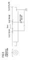
- FIG. 6 is a view showing the method for measuring a resistance value in the radial direction of the transfer roller 50 according to the first embodiment.
- the resistance value was measured under a temperature of 15° C. and a humidity of 10%.
- both ends of the core bar 51 are each pressed toward the metal drum with a force of 4.9 N.
- the transfer roller 50 is pressed against the metal drum with a force of 9.8 N.
- a voltage Vref applied to a reference resistance Rref when a voltage V 1 is applied to the core bar 51 is measured using a digital multi meter (manufactured by FLUKE Corporation).
- the voltage V 1 applied to the core bar 51 is 2000 V
- the reference resistance Rref is 1000 ⁇
- the voltage applied to the reference resistance Rref is measured for 10 seconds after 10 seconds elapse since the application of the voltage to the core bar 51 .
- an average of the voltages applied for 10 seconds is the voltage Vref.
- a resistance value Rm in the radial direction of the transfer roller 50 is calculated by the following formula.
- Rm V rol/ I rol (Formula 1)
- Vrol and Irol are calculated by the following formulae.
- V rol V 1 ⁇ V ref (Formula 2)
- I rol R ref/ V ref (Formula 3)
- Rm ( V 1 ⁇ V ref) ⁇ V erf/ R ref
- the resistance value Rm in the radial direction of the transfer roller 50 may be calculated with the measurement of the voltage Vref.
- the transfer roller 50 preferably has a resistance value Rm of 2.0 ⁇ 10 7 to 5.0 ⁇ 10 9 ⁇ in the radial direction. Therefore, in the embodiment, the transfer roller 50 has a resistance value Rm of 3.0 ⁇ 10 8 ⁇ in the radial direction.
- the photosensitive drum 1 is charged to have a negative polarity, and developed toner is also charged to have a negative polarity.
- a voltage having a positive polarity opposite to that of the toner is applied to the transfer roller 50 , and charges having a positive polarity are applied onto the rear surface of the recording member P when a discharge occurs between the transfer roller 50 and the recording member P.
- a toner image is electrostatically transferred from the photosensitive drum 1 onto the recording member P.
- a force with which the recording member P retains the toner image is determined based on the amount of charges obtained by subtracting the amount of charges having a negative polarity on the surface of the recording member P from the amount of charges having the positive polarity on the rear surface of the recording member P after the recording member P passes through the transfer nip portion Nt. That is, the recording member P may stably retain the toner image when the amount of the charges having the positive polarity on the rear surface of the recording member P is larger than the amount of the charges having the negative polarity on the surface of the recording member P.
- the amount of the charges on the rear surface of the recording member P after the recording member P passes through the transfer nip portion Nt is determined based on the amount of the discharge from the transfer roller 50 to the recording member P.
- the amount of the charges on the surface of the recording member P is the sum of the amount of the charges having the negative polarity of the toner and the amount of the charges having the negative polarity applied from the photosensitive drum 1 onto the recording member P.
- the amount of the charges having the negative polarity applied from the photosensitive drum 1 onto the recording member P is determined based on the amount of the discharge occurring between the photosensitive drum 1 and the recording member P on the downstream side of the transfer nip portion Nt in the transporting direction of the recording member P.
- the elastic layer provided on the transfer roller 50 is conventionally foamed to have a cell structure near the surface of the transfer roller 50 .
- the outer diameters of the cells constituting the foaming material are increased near the surface of the elastic layer of the transfer roller 50 .
- the interval between the recording member P and the transfer roller 50 may be increased at the transfer nip portion Nt with an increase in the cell diameter. Therefore, since the amount of the discharge occurring between the recording member P and the transfer roller 50 is increased, the amount of the charges applied onto the rear surface of the recording member P may be increased. As a result, the force with which the recording member P retains a toner image is increased, and an excellent image with no image failure may be obtained.
- the amount of the charges having the negative polarity applied onto the surface of the recording member P after the recording member P passes through the transfer nip portion Nt is determined based mainly on the amount of the discharge occurring between the photosensitive drum 1 and the recording member P on the downstream side of the transfer nip portion Nt in the transporting direction of the recording member P.
- the discharge occurring between the photosensitive drum 1 and the recording member P may be suppressed on the downstream side of the transfer nip portion Nt in the transporting direction of the recording member P.
- FIG. 7 is a view showing the relationship between the surface potential, the surface resistance Rs, and the resistance value Rm of the transfer roller 50 .
- a voltage applied to the core bar of the transfer roller 50 is a voltage Vp and a potential at a point T 1 on the downstream side of the transfer nip portion Nt in the transporting direction of the recording member P is a potential Vs.
- the surface potential of the transfer roller 50 at the transfer nip portion Nt is a potential Vnip
- a current fed from the transfer nip portion Nt to the core bar 51 is a current value Inip
- a current fed from the transfer nip portion Nt to the core bar 51 via the point T 1 is a current Is.
- Vs Vp ⁇ Rm ⁇ Is (Formula 4)
- V nip Vp ⁇ ( Rm+Rs ) ⁇ Is (Formula 5)
- the following formula may be obtained.
- Vs Vp ⁇ ( Vp ⁇ V nip)/(1 +Rs/Rm ) (Formula 6)
- a letter-sized Business 4200 (hereinafter called a letter sheet) manufactured by Xerox Corporation was used as the recording member P.
- a letter sheet left to stand for 48 hours in a low temperature and low humidity environment of a temperature of 15° C. and a humidity of 10% was used as the recording member P.
- a half-tone image was successively printed on ten sheets to confirm the presence or absence of the occurrence of an image failure.
- the voltage applied to the transfer roller 50 was 2000 V.
- a transfer roller in which an elastic layer 53 had a cell diameter larger than those of the embodiment and Comparative Example 1 was used as Conventional Example 1.
- the elastic layer 53 has a cell diameter of 300 ⁇ m in both the embodiment and Comparative Example 1.
- Rs/Rm is 3000 in the embodiment, while Rs/Rm is 9000 in Comparative Example 1.
- the discharge from the photosensitive drum 1 to the surface of the recording member P was suppressed on the downstream side of the transfer nip portion Nt in the transporting direction of the recording member P, whereby the amount of the charges having the negative polarity applied onto the surface of the recording member P was decreased.
- the force with which the recording member P retained the toner was increased, whereby the occurrence of “scattering” was suppressed.
- the value of Rm/Rs is the same between Comparative Example 1 and Conventional Example 1.
- the elastic layer 53 has a cell diameter of 500 ⁇ m in Conventional Example 1, while the elastic layer 53 has a cell diameter of 300 ⁇ m in Comparative Example 1. Therefore, it appears that the amount of the discharge from the transfer roller 50 to the recording member P was increased at the transfer nip portion Nt, and that the amount of the charges having the positive polarity applied onto the rear surface of the recording member P was increased. Therefore, it appears that the force with which the recording member P retained the toner was improved, and that the occurrence of “scattering” was suppressed.
- FIG. 8 is a diagram showing the relationship between the number of sheets in which “scattering” occurred and Rs/Rm in the first embodiment.
- a letter sheet left to stand for 48 hours in a low temperature and low humidity environment of a temperature of 15° C. and a humidity of 10% was used as the recording member P.
- a half-tone image was successively printed on ten sheets to confirm the presence or absence of an image failure.
- the transfer roller 50 was set such that the cell diameter of the elastic layer 53 was 300 ⁇ m, the surface resistance Rs was 1.5 ⁇ 10 10 to 3.0 ⁇ 10 12 ⁇ , the resistance value Rm was 3.0 ⁇ 10 8 ⁇ , and Rs/Rm was 50 to 10,000. As shown in FIG. 8 , the smaller the value of Rs/Rm, the more “scattering” was suppressed. When Rs/Rm was 4000, the occurrence of “scattering” was not confirmed.
- a potential Vd of the dark portion (the portion not irradiated with laser L) of the photosensitive drum 1 desirably becomes ⁇ 600 V after the photosensitive drum 1 is charged by the charging roller 2 .
- the potential Vd of the dark portion of the photosensitive drum 1 becomes, for example, only ⁇ 450 V or so. Therefore, the potential difference
- the pair of electrodes face each other in the axial direction of the transfer roller 50 and are arranged on the surface of the transfer roller 50 with an interval of 5 mm therebetween.
- the two electrodes have a width of 20 mm in the circumferential direction of the transfer roller 50 when arranged on the transfer roller 50 .
- the surface resistance of the transfer roller 50 when a current is fed between the electrodes in this state is Rs ( ⁇ ).
- the combined resistance of the elastic layer 52 and the elastic layer 53 is Rm ( ⁇ ).
- the relationship 150 ⁇ Rs ( ⁇ )/Rm ( ⁇ ) ⁇ 4000 is established in an environment of a temperature of 15° C. and a humidity of 10%.
- the discharge occurring between the photosensitive drum 1 and the recording member P may be suppressed, and the recording member P may be caused to reliably retain a toner image transferred onto the recording member P.
- the transfer roller 50 has an outer diameter of 8 mm to 15 mm.
- an increase in the manufacturing costs of the transfer roller 50 or the upsize of the image forming apparatus M may be suppressed.
- the elastic layer 53 is made of a foaming material, and the cells constituting the foaming material in the elastic layer 53 have an average outer diameter of 150 ⁇ m to 450 ⁇ m.
- the cell diameter is too large, the discharge becomes sparse and the shading of an image also becomes sparse.
- the cell diameter is too small, the discharge is not promoted between the transfer roller 50 and the recording member P, whereby the amount of the charges applied onto the rear surface of the recording member P is decreased.
- the above problems may be suppressed since the cells have an average outer diameter of 150 ⁇ m to 450 ⁇ m.
- the elastic layer of a transfer roller 60 in the second embodiment is constituted by only one elastic layer 62 .
- portions having the same functions as those of the first embodiment will be denoted by the same symbols, and their descriptions will be omitted.
- FIG. 9 is a cross-sectional view of the transfer roller 60 according to the second embodiment.
- the transfer roller 60 is constituted by a core bar 61 and the cylindrical elastic layer 62 that surrounds the outer peripheral surface of the core bar 61 .
- the transfer roller 60 has a length of 216 mm in its longitudinal direction (rotational center axial direction), the core bar 61 has an outer diameter ⁇ of 5 mm, the elastic layer 62 has a thickness of 3.75 mm.
- the elastic layer 62 is an elastic member made of a foaming material, and cells in a layer near the surface of the elastic layer 62 have a diameter of 300 ⁇ m.
- the transfer roller 60 presses a photosensitive drum 1 with a force of 9.8 N (1 kgf).
- the transfer roller 60 has the only one elastic layer 62 , and the value of Rs/Rm may be decreased with the adjustment of a vulcanization condition for manufacturing the transfer roller 60 .
- the value of Rs/Rm may be decreased even with an increase in the thickness of the elastic layer and an increase in the value of Rm.
- the transfer roller is caused to have a larger outer diameter, which results in a likelihood that the manufacturing costs of the transfer roller are increased or an image forming apparatus is upsized. Therefore, the transfer roller 60 preferably has an outer diameter of 8 mm to 15 mm.
- the transfer roller 60 has an outer diameter of 12.5 mm.
- a letter-sized Business 4200 (letter sheet) manufactured by Xerox Corporation was used as a recording member P.
- a letter sheet left to stand for 48 hours in a low temperature and low humidity environment of a temperature of 15° C. and a humidity of 10% was used as the recording member P. Then, a half-tone image was successively printed on ten sheets to confirm the presence or absence of an image failure.
- a voltage applied to the transfer roller 60 was 2000 V.
- the cell outer diameter of the elastic layer 62 was 300 ⁇ m
- the surface resistance Rs was 1.5 ⁇ 10 10 to 3.3 ⁇ 10 12 ⁇
- the resistance value Rm was 3.0 ⁇ 10 8 ⁇
- Rs/Rm was 50 to 10,000. Under the conditions, the presence or absence of “scattering” and “drum memory” was confirmed.
- FIG. 10 is a diagram showing the relationship between the number of sheets in which “scattering” occurred and Rs/Rm in the second embodiment.
- a solid line indicates the experimental results of the embodiment
- dashed lines indicate the experimental results of the first embodiment.
- the smaller the value of Rs/Rm the more “scattering” was suppressed in the embodiment similarly to the first embodiment.
- Rs/Rm was 4000
- the occurrence of “scattering” was not confirmed.
- “drum memory” did not occur when Rs/Rm was 150 but occurred when Rs/Rm was 100. From the results, it appears that the amount of charges having a negative polarity applied onto the surface of the recording member P may be decreased with a decrease in the value of Rs/Rm even when the transfer roller 60 has the one elastic layer 62 as in the second embodiment.
- the cell diameter of the elastic layer 62 may be increased so long as the value of Rs/Rm falls within the range of 150 to 4000. However, if the cell diameter of the elastic layer 62 is excessively increased, “roughness” occurs. For example, when the cell diameter of the elastic layer 62 is 500 ⁇ m and Rs/Rm is 3000, the occurrence of “scattering” is suppressed but “roughness” occurs.
- the elastic layer 62 of the transfer roller 60 preferably has a cell diameter of 150 to 450 ⁇ m. Further, the value of Rs/Rm is preferably 150 to 4000.
- FIGS. 11A and 11B are views each showing the transfer nip portion Nt between the photosensitive drum 1 and the transfer roller 50 according to the third embodiment.
- FIG. 11A an angle (winding angle ⁇ (see FIG. 2 )) at which the recording member P winds around the photosensitive drum 1 is small, and a transfer separating angle ⁇ (see FIG. 2 ) is small.
- FIG. 11B the winding angle ⁇ is large, and the transfer separating angle ⁇ is large.
- the winding angle ⁇ and the transfer separating angle ⁇ are defined as described above.
- an angle at which the recording member P enters the transfer nip portion Nt is increased with a change in the position of a pre-transfer guide 5 .
- the winding angle ⁇ at which the recording member P winds around the photosensitive drum 1 is increased.
- the transfer separating angle ⁇ is also increased on the downstream side of the transfer nip portion Nt in the transporting direction of the recording member P. This is because the transfer roller 50 is pressed by the recording member P in a direction opposite to a direction in which the transfer roller 50 presses the photosensitive drum 1 due to the elasticity of the recording member P.
- the transfer separating angle ⁇ when the transfer separating angle ⁇ is increased, the distance between the photosensitive drum 1 and the recording member P is increased on the downstream side of the transfer nip portion Nt in the transporting direction of the recording member P, whereby a discharge from the photosensitive drum 1 to the recording member P is intensified.
- the amount of charges having a negative polarity applied from the photosensitive drum 1 onto the recording member P is increased, and a force with which the recording member P retains toner is decreased. For this reason, there is a likelihood that an image failure occurs.
- the occurrence of an image failure may be suppressed with the adjustment of the value of Rs/Rm even when the transfer separating angle ⁇ is increased and the amount of the charges having the negative polarity applied onto the surface of the recording member P is increased.
- the position of the pre-transfer guide 5 and the winding angle ⁇ are different from those of the first embodiment, but the other configurations are the same.
- the quality of an image is improved if the winding angle ⁇ is large, but the recording member P may not be properly transported if the winding angle ⁇ is too large. It is generally said that the winding angle ⁇ is preferably 0° to 20°. Therefore, in the embodiment, the winding angle ⁇ is 15°.
- a letter-sized Business 4200 (hereinafter called a letter sheet) manufactured by Xerox Corporation was used as a recording member. Specifically, a letter sheet left to stand for 48 hours in a low temperature and low humidity environment of a temperature of 15° C. and a humidity of 10% was used as the recording member P. Then, a half-tone image was successively printed on ten sheets to confirm the presence or absence of an image failure. At this time, a voltage applied to the transfer roller 50 was 2000 V.
- the cell diameter of an elastic layer 53 of the transfer roller 50 was 300 ⁇ m
- the surface resistance Rs was 1.5 ⁇ 10 10 to 3.0 ⁇ 10 12 ⁇
- the resistance value Rm was 3.0 ⁇ 10 8 ⁇
- Rs/Rm was 50 to 10,000 like the first embodiment. Under the conditions, the presence or absence of the occurrence of “scattering” and “drum memory” was confirmed.
- FIG. 12 is a diagram showing the relationship between the number of sheets in which “scattering” occurred and Rs/Rm in the third embodiment. As shown in FIG. 12 , the smaller the value of Rs/Rm, the more “scattering” was suppressed. When Rs/Rm was 3000, the occurrence of “scattering” was not confirmed. In the first embodiment, the occurrence of “scattering” was not confirmed when Rs/Rm was 4000. In the embodiment, however, “scattering” occurred when Rs/Rm was 4000, and the occurrence of “scattering” was not confirmed when Rs/Rm was 3000.
- the transfer separating angle ⁇ becomes larger than that of the first embodiment, which results in an increase in the amount of the charges having the negative polarity applied onto the surface of the recording member P on the downstream side of the transfer nip portion Nt in the transporting direction of the recording member P. Therefore, it appears that “scattering” occurred since the force with which the recording member P retained toner was weakened.
- the value of Rs/Rm is set at 150 to 3000 to suppress “scattering.”
- “drum memory” did not occur when Rs/Rm was 150 but occurred when Rs/Rm was 100.
- the cell diameter of the elastic layer 53 of the transfer roller 50 may be increased so long as the value of Rs/Rm falls within the range of 150 to 3000.
- the cell diameter of the elastic layer 53 is excessively increased, there is a likelihood that “roughness” occurs as described above. For example, when the cell diameter of the elastic layer 53 is 500 ⁇ m and Rs/Rm is 3000, the occurrence of “scattering” may be suppressed but “roughness” occurs.
- a tangent of which the contact with the photosensitive drum 1 is closer to the transfer nip portion Nt among tangents from the sharp portion of a pre-transfer guide 5 to the outer peripheral surface of the photosensitive drum 1 is a straight line A
- a line segment that connects the center of the photosensitive drum 1 and the center of the transfer roller 50 to each other is a line segment B
- a line segment that connects the contact between the photosensitive drum 1 and the straight line A and the center of the photosensitive drum 1 to each other is a line segment C.
- an angle ⁇ (winding angle ⁇ ) formed by the line segments B and C is indicated as 0° ⁇ 20°, and the relationship between Rs ( ⁇ ) and Rm ( ⁇ ) is indicated as 150 ⁇ Rs ( ⁇ )/Rm ( ⁇ ) ⁇ 3000.
- the distance between the outer peripheral surface of the photosensitive drum 1 and the recording member P may be increased on the downstream side of the transfer nip portion Nt in the transporting direction of the recording member P.
- the resistance values Rs and Rm are adjusted since the transfer roller 50 has a plurality of elastic layers.
- the transfer roller 50 may be constituted by different layers.
- the transfer roller 50 may be constituted not only by elastic layers but also by different types of layers such as a coat layer and a tube layer.
Landscapes
- Physics & Mathematics (AREA)
- General Physics & Mathematics (AREA)
- Electrostatic Charge, Transfer And Separation In Electrography (AREA)
- Rolls And Other Rotary Bodies (AREA)
Abstract
Description
-
- a conductive core portion:
- a first layer that covers the core portion; and
- a second layer that covers the first layer, wherein the developer image is transferred onto the sheet at a nip portion between the photosensitive drum and the transfer roller when a voltage is applied to the core portion, and
- a relationship 150≤Rs (Ω)/Rm (Ω)≤4000 is established in an environment of a temperature of 15 C and a humidity of 10% in a case where
- a surface resistance of the transfer roller is Rs (Ω) when a current is fed between a pair of electrodes facing each other in an axial direction of the transfer roller and arranged on a surface of the transfer roller with an interval of 5 mm therebetween, the electrodes having a width of 20 mm in a circumferential direction of the transfer roller in a state of being arranged on the transfer roller, and
- in a case where
- a combined resistance of the first layer and the second layer is Rm (Ω) when the current is fed from the core portion to an outer peripheral surface of the second layer.
-
- the transfer roller; and
- a photosensitive drum, wherein
- an image is formed on a sheet when a developer image formed on the photosensitive drum is transferred onto a sheet.
Rm=Vrol/Irol (Formula 1)
Here, Vrol and Irol are calculated by the following formulae.
Vrol=V1−Vref (Formula 2)
Irol=Rref/Vref (Formula 3)
Here, when (Formula 2) and (Formula 3) are substituted into (Formula 1), the following formula is obtained.
Rm=(V1−Vref)×Verf/Rref
Vs=Vp−Rm×Is (Formula 4)
Vnip=Vp−(Rm+Rs)×Is (Formula 5)
From the above two formulae, the following formula may be obtained.
Vs=Vp−(Vp−Vnip)/(1+Rs/Rm) (Formula 6)
| TABLE 1 | |||||
| Cell Diameter | Rs/Rm | Roughness | Scattering | ||
| Embodiment | 300 | 3000 | ◯ | ◯ |
| Conventional | 500 | 9000 | X | ◯ |
| Example 1 | ||||
| Comparative | 300 | 9000 | ◯ | X |
| Example 1 | ||||
Claims (9)
Applications Claiming Priority (2)
| Application Number | Priority Date | Filing Date | Title |
|---|---|---|---|
| JP2016-119812 | 2016-06-16 | ||
| JP2016119812A JP6808368B2 (en) | 2016-06-16 | 2016-06-16 | Transfer roller and image forming device |
Publications (2)
| Publication Number | Publication Date |
|---|---|
| US20170363993A1 US20170363993A1 (en) | 2017-12-21 |
| US10025236B2 true US10025236B2 (en) | 2018-07-17 |
Family
ID=60659488
Family Applications (1)
| Application Number | Title | Priority Date | Filing Date |
|---|---|---|---|
| US15/619,910 Active US10025236B2 (en) | 2016-06-16 | 2017-06-12 | Transfer roller and image forming apparatus |
Country Status (2)
| Country | Link |
|---|---|
| US (1) | US10025236B2 (en) |
| JP (1) | JP6808368B2 (en) |
Families Citing this family (2)
| Publication number | Priority date | Publication date | Assignee | Title |
|---|---|---|---|---|
| JP2021039229A (en) | 2019-09-03 | 2021-03-11 | ヒューレット−パッカード デベロップメント カンパニー エル.ピー.Hewlett‐Packard Development Company, L.P. | Image formation system having transfer roller |
| JP7823449B2 (en) * | 2022-03-18 | 2026-03-04 | 株式会社リコー | Image forming device |
Citations (7)
| Publication number | Priority date | Publication date | Assignee | Title |
|---|---|---|---|---|
| US7486919B2 (en) | 2005-03-02 | 2009-02-03 | Oki Data Corporation | Transfer apparatus and image forming apparatus |
| US20090232530A1 (en) | 2008-02-28 | 2009-09-17 | Canon Kabushiki Kaisha | Image forming apparatus |
| US7773928B2 (en) * | 2006-05-08 | 2010-08-10 | Ricoh Company, Limited | Transfer-separation device and image forming apparatus |
| JP4639712B2 (en) | 2004-09-15 | 2011-02-23 | 富士ゼロックス株式会社 | Conductive roll and image forming apparatus provided with the same |
| US20110194880A1 (en) * | 2010-02-05 | 2011-08-11 | Canon Kasei Kabushiki Kaisha | Transfer roller |
| JP2012155263A (en) | 2011-01-28 | 2012-08-16 | Canon Chemicals Inc | Conductive sponge rubber roller and transfer roller |
| US9274462B2 (en) * | 2014-02-05 | 2016-03-01 | Fuji Xerox Co., Ltd. | Transfer member and image forming apparatus |
Family Cites Families (6)
| Publication number | Priority date | Publication date | Assignee | Title |
|---|---|---|---|---|
| JPH063974A (en) * | 1992-06-24 | 1994-01-14 | Canon Inc | Image forming device |
| JP3539550B2 (en) * | 1999-10-01 | 2004-07-07 | シャープ株式会社 | Conductive member and method of manufacturing the same |
| JP2001117375A (en) * | 1999-10-19 | 2001-04-27 | Canon Inc | Image forming device |
| JP2003241541A (en) * | 2002-02-14 | 2003-08-29 | Canon Inc | Image forming device |
| JP2004271836A (en) * | 2003-03-07 | 2004-09-30 | Fuji Xerox Co Ltd | Conductive roll and image forming apparatus using the same |
| JP5970850B2 (en) * | 2012-02-21 | 2016-08-17 | 富士ゼロックス株式会社 | Transfer roll, image forming apparatus, and process cartridge |
-
2016
- 2016-06-16 JP JP2016119812A patent/JP6808368B2/en active Active
-
2017
- 2017-06-12 US US15/619,910 patent/US10025236B2/en active Active
Patent Citations (9)
| Publication number | Priority date | Publication date | Assignee | Title |
|---|---|---|---|---|
| JP4639712B2 (en) | 2004-09-15 | 2011-02-23 | 富士ゼロックス株式会社 | Conductive roll and image forming apparatus provided with the same |
| US7486919B2 (en) | 2005-03-02 | 2009-02-03 | Oki Data Corporation | Transfer apparatus and image forming apparatus |
| JP5116947B2 (en) | 2005-03-02 | 2013-01-09 | 株式会社沖データ | Transfer device and image forming apparatus |
| US7773928B2 (en) * | 2006-05-08 | 2010-08-10 | Ricoh Company, Limited | Transfer-separation device and image forming apparatus |
| US20090232530A1 (en) | 2008-02-28 | 2009-09-17 | Canon Kabushiki Kaisha | Image forming apparatus |
| US20140105643A1 (en) | 2008-02-28 | 2014-04-17 | Canon Kabushiki Kaisha | Image forming apparatus having a brush member |
| US20110194880A1 (en) * | 2010-02-05 | 2011-08-11 | Canon Kasei Kabushiki Kaisha | Transfer roller |
| JP2012155263A (en) | 2011-01-28 | 2012-08-16 | Canon Chemicals Inc | Conductive sponge rubber roller and transfer roller |
| US9274462B2 (en) * | 2014-02-05 | 2016-03-01 | Fuji Xerox Co., Ltd. | Transfer member and image forming apparatus |
Also Published As
| Publication number | Publication date |
|---|---|
| JP6808368B2 (en) | 2021-01-06 |
| US20170363993A1 (en) | 2017-12-21 |
| JP2017223864A (en) | 2017-12-21 |
Similar Documents
| Publication | Publication Date | Title |
|---|---|---|
| US8811868B2 (en) | Fusing unit and image forming apparatus employing the same | |
| US6681094B2 (en) | Intermediate transfer member belt/roller configuration for single-pass color electrophotographic printer | |
| US9501007B2 (en) | Image forming apparatus | |
| JP6532355B2 (en) | Image forming device | |
| US7440711B2 (en) | Image-forming apparatus having cleaning roller to remove toner from transfer roller that facilitates transferring toner image from image-bearing member to recording material | |
| CN109765767B (en) | Image forming apparatus with a toner supply device | |
| US10025236B2 (en) | Transfer roller and image forming apparatus | |
| US7693438B2 (en) | Image transfer device, image forming apparatus having the image transfer device, and method of measuring resistance of a printing medium or an endless track belt of the image forming apparatus | |
| JP7739104B2 (en) | Image forming device | |
| JP2010175952A (en) | Image forming apparatus | |
| US10444673B2 (en) | Guide member and image forming apparatus comprising the same | |
| JP3368222B2 (en) | Image forming device | |
| CN103492959B (en) | Image processing system | |
| US10222718B2 (en) | Image forming apparatus for duplex operation using potential differences | |
| JP5267865B2 (en) | Electrostatic recording device | |
| JP2019133203A (en) | Image forming apparatus | |
| US12517450B2 (en) | Image forming apparatus | |
| JP2006220974A (en) | Transfer device and image forming apparatus | |
| US11835912B2 (en) | Image forming apparatus | |
| JP2000131974A (en) | Fixing device and image forming device | |
| JP4521939B2 (en) | Image forming apparatus | |
| JP5101330B2 (en) | Transfer apparatus and electrostatic recording apparatus using the same | |
| JPH11184281A (en) | Transfer voltage control method in image forming apparatus | |
| JP2010145815A (en) | Image forming apparatus | |
| JP2009053272A (en) | Image forming apparatus |
Legal Events
| Date | Code | Title | Description |
|---|---|---|---|
| AS | Assignment |
Owner name: CANON KABUSHIKI KAISHA, JAPAN Free format text: ASSIGNMENT OF ASSIGNORS INTEREST;ASSIGNORS:SASAME, HIROKI;KOBAYASHI, SHINSUKE;AKAMATSU, TAKAAKI;AND OTHERS;SIGNING DATES FROM 20170524 TO 20170530;REEL/FRAME:043597/0899 |
|
| STCF | Information on status: patent grant |
Free format text: PATENTED CASE |
|
| MAFP | Maintenance fee payment |
Free format text: PAYMENT OF MAINTENANCE FEE, 4TH YEAR, LARGE ENTITY (ORIGINAL EVENT CODE: M1551); ENTITY STATUS OF PATENT OWNER: LARGE ENTITY Year of fee payment: 4 |
|
| MAFP | Maintenance fee payment |
Free format text: PAYMENT OF MAINTENANCE FEE, 8TH YEAR, LARGE ENTITY (ORIGINAL EVENT CODE: M1552); ENTITY STATUS OF PATENT OWNER: LARGE ENTITY Year of fee payment: 8 |