US10024966B2 - Efficient implementation of distance de-aliasing for ranging systems using phase domain computation - Google Patents
Efficient implementation of distance de-aliasing for ranging systems using phase domain computation Download PDFInfo
- Publication number
- US10024966B2 US10024966B2 US15/009,332 US201615009332A US10024966B2 US 10024966 B2 US10024966 B2 US 10024966B2 US 201615009332 A US201615009332 A US 201615009332A US 10024966 B2 US10024966 B2 US 10024966B2
- Authority
- US
- United States
- Prior art keywords
- point
- frequencies
- bin
- electromagnetic radiation
- distance
- Prior art date
- Legal status (The legal status is an assumption and is not a legal conclusion. Google has not performed a legal analysis and makes no representation as to the accuracy of the status listed.)
- Active, expires
Links
Images


Classifications
-
- G—PHYSICS
- G01—MEASURING; TESTING
- G01S—RADIO DIRECTION-FINDING; RADIO NAVIGATION; DETERMINING DISTANCE OR VELOCITY BY USE OF RADIO WAVES; LOCATING OR PRESENCE-DETECTING BY USE OF THE REFLECTION OR RERADIATION OF RADIO WAVES; ANALOGOUS ARRANGEMENTS USING OTHER WAVES
- G01S17/00—Systems using the reflection or reradiation of electromagnetic waves other than radio waves, e.g. lidar systems
- G01S17/02—Systems using the reflection of electromagnetic waves other than radio waves
- G01S17/06—Systems determining position data of a target
- G01S17/08—Systems determining position data of a target for measuring distance only
- G01S17/32—Systems determining position data of a target for measuring distance only using transmission of continuous waves, whether amplitude-, frequency-, or phase-modulated, or unmodulated
- G01S17/36—Systems determining position data of a target for measuring distance only using transmission of continuous waves, whether amplitude-, frequency-, or phase-modulated, or unmodulated with phase comparison between the received signal and the contemporaneously transmitted signal
-
- G—PHYSICS
- G01—MEASURING; TESTING
- G01S—RADIO DIRECTION-FINDING; RADIO NAVIGATION; DETERMINING DISTANCE OR VELOCITY BY USE OF RADIO WAVES; LOCATING OR PRESENCE-DETECTING BY USE OF THE REFLECTION OR RERADIATION OF RADIO WAVES; ANALOGOUS ARRANGEMENTS USING OTHER WAVES
- G01S17/00—Systems using the reflection or reradiation of electromagnetic waves other than radio waves, e.g. lidar systems
- G01S17/88—Lidar systems specially adapted for specific applications
- G01S17/89—Lidar systems specially adapted for specific applications for mapping or imaging
- G01S17/894—3D imaging with simultaneous measurement of time-of-flight at a 2D array of receiver pixels, e.g. time-of-flight cameras or flash lidar
-
- G—PHYSICS
- G01—MEASURING; TESTING
- G01S—RADIO DIRECTION-FINDING; RADIO NAVIGATION; DETERMINING DISTANCE OR VELOCITY BY USE OF RADIO WAVES; LOCATING OR PRESENCE-DETECTING BY USE OF THE REFLECTION OR RERADIATION OF RADIO WAVES; ANALOGOUS ARRANGEMENTS USING OTHER WAVES
- G01S7/00—Details of systems according to groups G01S13/00, G01S15/00, G01S17/00
- G01S7/48—Details of systems according to groups G01S13/00, G01S15/00, G01S17/00 of systems according to group G01S17/00
- G01S7/491—Details of non-pulse systems
- G01S7/4912—Receivers
- G01S7/4915—Time delay measurement, e.g. operational details for pixel components; Phase measurement
Definitions
- aspects of this disclosure are directed, in general, to distance measurement and, more specifically, to efficient implementation of distance de-aliasing for ranging systems using phase domain computations.
- ranging systems use a single frequency, continuous wave for ranging. Such systems measure the phase of the received reflected wave with respect to the transmitted wave to measure the distance of the object in the scene. The phase of the returning wave “wraps” at 2 ⁇ , thereby leading to a distance ambiguity.
- a common technique to extend the range is to use another frequency of operation and extend the unambiguous range to the Least Common Multiple (LCM) of the two ranges.
- LCM Common Multiple
- the calculations involved are complex and requiring significant Integrated Circuit (IC) silicon area and/or time to compute the de-aliased (actual) distance.
- a search for the best match is typically performed in the distance domain after converting the plurality of acquired phases to distances.
- Some existing methods use a search algorithm to find the closest match for the two frequencies to find the bin (set) in which the object lies. The search takes a O(n) time where, n is proportional to the range extension (i.e. extension beyond wrap of the phase of the measuring frequencies) if implemented on a serial processor or takes O(n) silicon area if implemented in a parallel processor.
- Some existing methods use a divider to compute with O(1) time complexity, but dividers are expensive in terms of IC silicon area and/or processor time.
- aspects of the disclosure provide an implementation for determining a distance to a surface of interest, such as, for example in a Time of Flight (ToF) system, includes projecting modulated electromagnetic radiation of at least two frequencies to a point on the surface of interest, receiving the electromagnetic radiation reflected from the point on the surface of interest.
- a weighted phase difference between the received frequencies may be calculated, in accordance with the present systems and methods, and respective bins for each of the reflected frequencies for an actual distance to the point on the surface of interest is calculated using the weighted phase difference.
- a final phase of the bin for the actual distance to the point on the surface of interest may be calculated as a weighted average of phases of the respective bins based on the signal strengths of the at least two reflected frequencies. The actual distance to the point on the surface of interest is then output.
- a ToF system may, in accordance with embodiments of the present systems and methods, include at least one illumination module to project modulated electromagnetic radiation of at least two frequencies to a point on a surface of interest, a sensor configured to receive and demodulate electromagnetic radiation reflected from the surface of interest and a ToF controller apparatus operatively coupled to the sensor.
- the controller apparatus may take the form of, and/or employ a time of flight distance de-aliasing apparatus that includes an input from at least one time of flight sensor apparatus to receive a demodulated phase of each at least two projected electromagnetic radiation frequencies reflected from a point on a surface of interest and a depth engine.
- This depth engine may be configured to calculate a weighted phase difference between the frequencies and calculate one bin for each of the reflected frequencies for an actual distance to the point on the surface of interest using the weighted phase difference and calculate the actual distance to the point on the surface of interest based on the final phase.
- An output may be configured to output the actual distance to the point on the surface of interest.
- This apparatus may also include a memory interface, coupled to an external memory, and the depth engine may temporarily store at least a portion of the data associated with demodulated electromagnetic radiation to the external memory for processing in accordance with the present systems and methods.
- Calculating the weighted phase difference between the frequencies may include monotonically increasing a value for the weighted phase difference from zero by a difference between the products of a coefficient for each frequency and a phase for each corresponding frequency.
- the coefficient for each frequency may be proportional to a weight of signal strength of received electromagnetic radiation of each respective frequency in some aspects of the present systems and methods.
- Using the calculated weighted phase difference to calculate one bin for each of the frequencies for an actual distance to the point on the surface of interest includes, for each bin, may include performing a bit-wise right shift operation on a product of the weighted phase difference and an integer proportional to a frequency associated with that bin.
- Calculating one bin for each of the frequencies for an actual distance to the point on the surface of interest using the weighted phase difference may include comparing an absolute value of the residue of each bin for each of the frequencies to determine which bin has a residue that is greater than or equal to the other bin.
- Certain alternative aspects may call for also calculating an unambiguous phase for each of the frequencies using the one bin for each of the frequencies and calculating a final phase of the bin for the actual distance to the point on the surface of interest using the unambiguous phase, using weights operating on the unambiguous phase for each of the frequencies.
- Using weights operating on the unambiguous phase for each of the frequencies may include calculating a weighted average of the unambiguous phases of the frequencies using weights based on signal strengths of received electromagnetic radiation of the frequencies.
- FIG. 1 is a diagrammatic representation of single-frequency ranging, according to some embodiments.
- FIG. 2 is a diagrammatic representation of multi-frequency ranging, according to some embodiments.
- FIG. 3 is a block diagram of a 3D ToF camera implementation using a ToF sensor and a controller, in accordance with some embodiments;
- FIG. 4 is a block diagram of a 3D ToF distance de-aliasing apparatus, in accordance with some embodiments.
- FIG. 5 is a flowchart of an implementation of efficient distance de-aliasing for ranging systems using phase domain computation, in accordance with some embodiments
- FIG. 6 is a flowchart of another implementation of efficient distance de-aliasing for ranging systems using phase domain computation, in accordance with some embodiments.
- FIGS. 7A through 7D graph implementation of an embodiment of the present systems and methods for distance de-aliasing using the phase domain, in accordance with some embodiments.
- Time of Flight (ToF) cameras provide a depth map of a scene.
- the depth map of the entire scene is captured at the same instant with an array of ToF pixels.
- a time-of-flight camera is a range imaging camera system that resolves distance based on the known speed of light, measuring the time-of-flight of a light signal between the camera and the subject for each point of the image.
- a time-of-flight camera generally includes an illumination unit that illuminates the subject with light modulated with frequencies up to 100 MHz.
- the illumination unit normally uses infrared light to make the illumination unobtrusive.
- a lens can be used to gather the reflected light and images the environment onto an image sensor, with an optical band-pass filter passing the light with the same wavelength as the illumination unit. This helps suppress non-pertinent light and reduce noise.
- each pixel measures the time the light has taken to travel from the illumination unit to the object and back to the sensor. From this time, a distance to the subject at that point can be determined.
- ranging systems may use a single frequency, continuous wave for ranging. Such systems measure the phase of the received reflected wave with respect to the transmitted wave to measure the distance of the object in the scene. The phase of the returning wave “wraps” at 2 ⁇ , thereby leading to a distance ambiguity.
- FIG. 1 is a diagrammatic representation of single-frequency ranging 100 , according to some embodiments. Therein, the single-frequency ranging process returns several possible distances corresponding to possible measured locations 102 a through 102 e of an object of interest. The distance corresponding to a measured location of the object may refer to the distance between the measured location of the object and the camera.
- the distance to measured location 102 c is the actual distance to the object of interest
- the distance to measured location 102 a is the measured unambiguous distance within an unambiguous range (d u ) 104 a of the frequency (i.e. within 2 ⁇ ) employed by camera 106
- the distances to measured locations 102 b, 102 d and 102 e are further possible distances returned as a result of wrapping of the frequency beyond a to provide further ambiguous ranges 104 b through 104 e.
- FIG. 2 is a diagrammatic representation of multi-frequency ranging 200 , according to some embodiments.
- illustrated two-frequency ranging returns several more possible distances to measured locations 202 a through 202 d and 203 a through 203 d to an object of interest.
- 203 c is the actual location of the object of interest.
- the distance to measured location 202 a is a measured unambiguous distance within an unambiguous range (d uA ) 204 a of a first frequency (i.e.
- locations 202 b through 202 d are further possible locations returned as a result of wrap of the first frequency beyond 2 ⁇ to provide further ambiguous ranges 204 b through 204 e.
- the second frequency also returns locations 203 a, 203 b and 203 d.
- the distance to location 203 a is a measured unambiguous distance within an unambiguous range (d uB ) 205 a of the second frequency (i.e.
- locations 203 b and 203 d are further possible distances returned as a result of wrapping of the first frequency beyond a to provide further ambiguous ranges 205 b through 205 d. Since the measurements from the two frequencies will not match perfectly, a search for the best match is typically performed in the distance domain after converting the plurality of acquired phases to distances. However, the calculations involved are complex and require significant Integrated Circuit (IC) silicon area and/or time to compute the de-aliased (actual) distance.
- IC Integrated Circuit
- Embodiments of the present systems and methods provide efficient implementation of distance de-aliasing for multi-frequency ranging systems, such as may be used in three dimensional (3D) ToF cameras, through the use of phase domain computations.
- Applications for a three dimensional (3D) camera employing ToF include presence detection, object location, movement detection, and 3D scanning.
- a ToF 3D camera may employ a ToF sensor and a controller, or the like.
- FIG. 3 is a block diagram of 3D ToF camera implementation 300 using ToF sensor 302 and controller 304 , in accordance with some embodiments.
- Either or both of sensor 302 and controller 304 may include one or more Integrated Circuits (ICs), or the like, separately or together.
- ICs Integrated Circuits
- a technique to extend the range of a ranging system uses two frequencies of operation to extend the unambiguous range to the LCM of the two ranges.
- ToF camera system 300 employs at least one illumination module, which may be made-up an illumination driver such as may be provided via sensor engine 306 and illumination source 308 , which is configured to project modulated electromagnetic radiation of at least two frequencies 310 and 312 , such as through illumination optics 314 , to point 316 on surface of interest 318 .
- Sensor engine 306 may also be configured to receive electromagnetic radiation 320 and 322 reflected from the surface of interest, via sensor pixel array 324 , such as may be received back at camera 300 through lens 326 . Sensor engine 306 may also demodulate electromagnetic radiation 320 and 322 reflected from the surface of interest and provide phase measurements of the electromagnetic radiation 320 and 322 reflected from the surface of interest and/or data related thereto to controller 304 .
- controller 304 is operatively coupled to sensor 302 .
- Controller 304 may compute a de-aliased distance of the point on the surface of interest using the phase measurements from the electromagnetic radiation 320 and 322 reflected from the surface of interest.
- Controller 304 may be coupled to external memory 328 .
- Controller 304 may temporarily store at least a portion of data associated with demodulated electromagnetic radiation, such as received from sensor 302 for processing.
- the de-aliased distance to the point on the surface of interest may be output by controller 306 as depth data, or the like, to at least one host device.
- FIG. 4 is a block diagram of a 3D ToF distance de-aliasing apparatus 400 , in accordance with some embodiments.
- Apparatus 400 may be employed as controller 304 of camera 300 , or as a part thereof.
- ToF distance de-aliasing apparatus 400 includes input interface 402 which may be operatively coupled to receive input from at least one ToF sensor apparatus, such as sensor 302 .
- apparatus 400 is configured to receive demodulated phase measurements of each of two or more projected electromagnetic radiation frequencies reflected from a point on a surface of interest.
- This phase data may be passed to and employed by distance de-aliasing apparatus depth engine 404 to compute the de-aliased distance of the point on the surface of interest using the phase measurements from projected electromagnetic radiation reflected from the surface of interest.
- These computations may be carried-out in accordance with implementations 500 and/or 600 described below, with respect to FIGS. 5 and 6 .
- Distance de-aliasing apparatus 400 may further include memory controller 406 configured to interface with external memory (such memory 328 of camera 300 ). Depth engine 404 may temporarily store at least a portion of received data associated with demodulated electromagnetic radiation, such as received sensor data, for processing to compute the de-aliased distance of the point on the surface of interest. Distance de-aliasing apparatus 400 may also include an output interface adapted to output the de-aliased distance to the point on the surface of interest as depth data, or the like, to at least one host device.
- Embodiments of the present systems and methods may efficiently implement distance de-aliasing for ranging systems using phase domain computation to extend the unambiguous range of Time of Flight (ToF) cameras, or the like.
- FIG. 5 is a flowchart of implementation 500 of efficient distance de-aliasing for ranging systems using phase domain computation, in accordance with some embodiments.
- a distance to a surface of interest is determined in a ToF ranging system, such as system 300 illustrated and described above.
- Working in the phase domain instead of the distance domain enables use of more efficient computations of the de-aliased distance of the object, given two phase measurements from the use of two frequencies.
- modulated electromagnetic radiation of at least two frequencies is projected to a point on the surface of interest, such as via illumination functionality of the ToF system at 502 .
- electromagnetic radiation reflected from the point on the surface of interest is received, such as by a sensor of the ToF system and is demodulated at 506 to provide phases of reflected electromagnetic radiation corresponding to the at least two frequencies to a depth engine ( 404 ).
- Such demodulation may be performed by diverting generated electrons to one node or the other of the sensor ( 302 ).
- Such direct demodulation may be considered a type of homodyning and may provide amplitude demodulation at a modulation frequency. That is, the demodulation frequency and modulation frequency are the same. Therefore, correlation between the demodulation frequency and modulation frequency is reflective of a phase to be provided to the depth engine ( 404 ).
- the unambiguous range to a point of interest in a ToF system is defined by the modulation frequency (f). If the total range of the application is beyond the unambiguous range for a given modulation frequency, de-aliasing can be enabled to extend the unambiguous range.
- This technique employs two modulation frequencies (f 1 and f 2 ).
- Embodiments of the present systems and methods call for working in the phase domain instead of the distance domain for finding the correct bin, that is, the bin in which the subject object lies.
- Implementation of the present systems and methods have a complexity of O(1) and do not use any division operations. Hence, when implemented in an IC, or the like it occupies less die area, or takes less time for computation, compared to existing de-aliasing systems and methods.
- At least two frequencies, f 1 and f 2 are used for distance measurement
- at least two phases, p 1 and p 2 are obtained, such as in steps 502 through 506 discussed above (e.g. as a result of demodulation at 506 of the electromagnetic radiation reflected from the point on the surface of interest).
- the phases are N-bit numbers where the full scale value corresponds to 2 ⁇
- a weighted phase difference (p d ) between the phases obtained (in step 506 ) for the at least two frequencies is calculated by a depth engine ( 404 ) or the like.
- This calculation of the weighted phase difference between the at least two frequencies may include monotonically increasing a value for the weighted phase difference from zero by a difference between the products of a coefficient for each frequency and a phase for each corresponding frequency.
- & is used to denote the “bit-wise AND” operation. (Bitwise AND takes two equal-length binary representations and performs the logical AND operation on each pair of the corresponding bits, by multiplying them.)
- the coefficient for each frequency (k 1 and k 2 ) may be calculated such that they are each proportional to a weight of signal strength of received electromagnetic radiation of each respective frequency, to provide further efficiency in accordance with various embodiments of the present systems and methods.
- one bin for each of the at least two frequencies for an actual distance to the point on the surface of interest is calculated, by the depth engine, or the like, using the weighted phase difference, such as by performing a bit-wise right shift operation on a product of the weighted phase difference and an integer proportional to a phase associated with each frequency.
- An unambiguous phase for each of the frequencies may be calculated at 512 using the one bin for each of the frequencies for the actual distance to the point on the surface of interest.
- the “signed( )” function treats a binary number as if it is represented in two's complement form, that is, to convey that the binary representation is converted into a signed number before using it as a residue for determining which of the bins is accurate and which of the bins is inaccurate.
- the absolute value (abs) of the residue of bin 1 (res 1 ) is greater than the absolute value of the residue of bin 2 (res 2 ) (i.e. (abs)(res 1 )>abs(res 2 ))
- b 1 is inaccurate.
- the inaccurate bin can then be then corrected by adding or subtracting one so as to make the inaccurate bin equal to the bring the accurate bin. That is, when the inaccurate bin's residue is negative, one is subtracted to correct the inaccurate bin; or when the inaccurate bin's residue is positive, one is added to the inaccurate bin to correct the inaccurate bin.
- the final computed phase (p u ) equals the weighted average of the phases p n1 and p n2 , where the weights (w 1 and w 2 ) are computed based on the signal strengths of the two measurements.
- p u ( w 1 *p n1 +w 2 *p n2 )/( w 1 +w 2 )
- a final phase used for computing, and/or selecting the bin containing the de-aliased distance of the point on the surface of interest may be calculated using weights operating on the unambiguous phase for each of the frequencies at 514 .
- the final de-aliased phase may be used to calculate the distance to the point of interest.
- the actual distance to the point on the surface of interest such as may be calculated or selected from a bin using the final phase, and may be output at 518 , such as to a host device or system.
- equation 4 calculates a weighted phase difference (p d ) using coefficients k 1 and k 2 and phases p 1 and p 2 . Then, equations 5 and 6 (and 9 and 10) determine the correct bins for each frequency, using p d . Equations 7 and 8 provide the unambiguous phases p n1 and p n2 using the calculated bins. The final phase is then calculated using weights w 1 and w 2 operating on p n1 and p n2 , such that the final computed phase equals the weighted average of the phases p n1 and p n2 , where the weights are computed based on the signal strengths of the two measurements.
- FIG. 6 is a flowchart of another implementation ( 600 ) of efficient distance de-aliasing for ranging systems using phase domain computation, in accordance with some embodiments.
- a distance to a surface of interest is also determined in a ToF ranging system, such as system 300 illustrated and described above.
- modulated electromagnetic radiation of at least two frequencies is projected to a point on the surface of interest, such as via illumination functionality of the ToF system at 602 .
- the electromagnetic radiation reflected from the point on the surface of interest is received by a sensor of the ToF system, or the like, and is demodulated at 606 to provide phases of reflected electromagnetic radiation corresponding to the at least two frequencies to a depth engine ( 404 ).
- a depth engine 404
- at least two frequencies, f 1 and f 2 are used for distance measurement
- at least two phases, p 1 and p 2 are obtained.
- coefficient (k 1 and k 2 ) for each frequency used in equations 3 and 4 to to calculate p d may be calculated at 608 such that they are each proportional to a weight of signal strength of received electromagnetic radiation of each respective frequency, to provide further efficiency in accordance the embodiment of FIG. 6 .
- a final phase used for computing, and/or selecting the bin containing the de-aliased distance of the point on the surface of interest may be calculated using weights operating on the unambiguous phase for each of the frequencies at 614 .
- the actual distance to the point on the surface of interest such as may be calculated or selected from a bin using the final phase, and may be output at 618 , such as to a host device or system.
- D is the full unambiguous distance and d is the actual distance of the object.
- Y is some integer which may have to change with distance as the phases p 1 and p 2 wrap. k 1 and k 2 need to be found.
- Y's can be eliminated by stripping the Most Significant Bits (MSBs) in the calculation, such as, in the present context, through operation of equation 4, wherein the weighted phase difference between the reflected frequencies is calculated by monotonically increasing a value for the weighted phase difference from zero by a difference between the products of a coefficient for each frequency and a phase for each corresponding frequency.
- MSBs Most Significant Bits
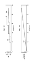
- FIGS. 7A through 7D graph implementation of an embodiment of the present systems and methods for distance de-aliasing using the phase domain, in accordance with some embodiments.
- FIGS. 7A through 7D are simulated results of application of an embodiment of the present systems and methods for a first frequency (f 1 ) of 30 MHz and a second frequency (f 2 ) of 18 MHz with phases (N) of 16 bits, (where, as noted the phases are a N-bit number where the full scale value corresponds to 2 ⁇ ).
- FIG. 7A shows a graph of the individual phases of two simultaneous ranging frequencies f 1 and f 2 over the same distances.
- line 702 is representative of a 30 MHz measurement frequency
- line 704 is representative of a 18 MHz measurement frequency f 2
- FIG. 7B graphs weighted phase difference 706 over the same distances upon application of equations 2 through 4, above.
- FIG. 7C graphs the resulting distance bins (b 1 708 and b 2 710 ) upon application of equation set 5 and 6 above.
- FIG. 7D graphs the calculated distance 712 following use of the residues of the bins, calculated using equation set 9 and 10 above, to determine which is incorrect by determining that (abs)(res 1 ) ⁇ abs(res 2 )), which means that b 2 is incorrect.
- f 1 is providing the proper measured distance in accordance with the present systems and methods for efficient implementation of distance de-aliasing for ranging systems using the phase domain.
- b 2 can be corrected by adding one.
- complexity of de-aliasing is reduced to O(1).
- the present systems and methods do not employ dividers, as compared to some other algorithms, and hence the present systems and methods require lower IC implementation area.
- the reduction of complexity reduces IC implementation area and processing requirements.
- a silicon area reduction of about fifty to sixty percent can be realized in ranging system ICs and/or ranging components of other ICs, with even greater reductions in Field-Programmable Gate Arrays (FPGAs) because of the use of existing multipliers in the computation(s).
- FPGAs Field-Programmable Gate Arrays
- existing hardware multipliers may be used for calculations such as, k 1 *p d1 ⁇ k 2 *p d2 and the like.
- ToF applications particularly three-dimensional (3D) ToF applications, which include both industrial and intuitive consumer user interface applications, can make use of the present systems and method reduce die area on an Application Specific Integrated Circuit (ASIC) or logical element usage on an FPGA implementing ranging in accordance with the present efficient implementation of distance de-aliasing for ranging systems using phase domain computation.
- ASIC Application Specific Integrated Circuit
Landscapes
- Physics & Mathematics (AREA)
- Engineering & Computer Science (AREA)
- Computer Networks & Wireless Communication (AREA)
- Electromagnetism (AREA)
- General Physics & Mathematics (AREA)
- Radar, Positioning & Navigation (AREA)
- Remote Sensing (AREA)
- Optical Radar Systems And Details Thereof (AREA)
- Radar Systems Or Details Thereof (AREA)
Abstract
Description
R=c/2*GCD(f 1 ,f 2) Eq. 1
wherein c is the speed of light and GCD is the Greatest Common Devisor.
f 1 /f 2 =m 1 /m 2 Eq. 2
then constants k1, k2 may be pre-computed such that the following relationship is met:
k 1 ×m 1 −k 2 ×m 2=1 Eq. 3
p d=(k 1 ×p 1 −k 2 ×p 2)&(2N−1) Eq. 4
Where, “&” is used to denote the “bit-wise AND” operation. (Bitwise AND takes two equal-length binary representations and performs the logical AND operation on each pair of the corresponding bits, by multiplying them.) As discussed in greater detail below, the coefficient for each frequency (k1 and k2) may be calculated such that they are each proportional to a weight of signal strength of received electromagnetic radiation of each respective frequency, to provide further efficiency in accordance with various embodiments of the present systems and methods.
b 1=(p d *m 1)>>N Eq. 5
b 2=(p d *m 2)>>N Eq. 6
Where, b1 and b2 correspond to the calculated bins and >> represents the bit-wise right shift operator.
p n1=(b 1 <<N+p 1)*m 2 Eq. 7
p n2=(b 2 <<N+p 2)*m 1 Eq. 8
Where, << represents the bit-wise left shift operator.
res1=signed((p d *m 1)&(2N−1)) Eq. 9
res2=signed((p d *m 1)&(2N−1)) Eq. 10
p u=(w 1 *p n1 +w 2 *p n2)/(w 1 +w 2) Eq. 11
Distance=R*p u/(2^(number of bits used to represent p u)) Eq. 12
Where unambiguous range, R is calculated from equation 1.
k 1 /k 2 =w 1 /w 2 Eq. 13
eliminates need to calculate the unambiguous phases pn1 and pn2 using the bins and eliminates need to calculate the final phase using weights w1 and w2, operating on pn1 and pn2, thereby reducing computation further.
k 1 ×m 1 −k 2 ×m 2=1 Eq. 14
then:
(k 1 +m 2)×m 1−(k 2 +m 1)×m 2=1 Eq. 15
pow(k 1 , n×(1+m 1))×m 1 −k 2 ×m 2=1 Eq. 16
or, that is:
(k 1 n×(1+m
where n is an integer.
k 1 *p 1 −k 2*p2 +Y=d/D Eq. 18
which is monotonous with increase in distance. D is the full unambiguous distance and d is the actual distance of the object. Y is some integer which may have to change with distance as the phases p1 and p2 wrap. k1 and k2 need to be found.
k 1 *m 1 *d/D−k 2 *m 2 *d/D+Y=d/D Eq. 19
m1*d/D and m2*d/D need to roll at 1. So Y will change accordingly. Therefore:
(k 1 *m 1 −k 2 *m 2)*d/D+Y=d/D Eq. 20
Therefore, if k1*m1−k2*m2=1, and if Y can be eliminated, the equation balances. Y's can be eliminated by stripping the Most Significant Bits (MSBs) in the calculation, such as, in the present context, through operation of equation 4, wherein the weighted phase difference between the reflected frequencies is calculated by monotonically increasing a value for the weighted phase difference from zero by a difference between the products of a coefficient for each frequency and a phase for each corresponding frequency.
Claims (20)
Priority Applications (1)
| Application Number | Priority Date | Filing Date | Title |
|---|---|---|---|
| US15/009,332 US10024966B2 (en) | 2015-01-28 | 2016-01-28 | Efficient implementation of distance de-aliasing for ranging systems using phase domain computation |
Applications Claiming Priority (3)
| Application Number | Priority Date | Filing Date | Title |
|---|---|---|---|
| US201562108885P | 2015-01-28 | 2015-01-28 | |
| US201562273858P | 2015-12-31 | 2015-12-31 | |
| US15/009,332 US10024966B2 (en) | 2015-01-28 | 2016-01-28 | Efficient implementation of distance de-aliasing for ranging systems using phase domain computation |
Publications (2)
| Publication Number | Publication Date |
|---|---|
| US20160216376A1 US20160216376A1 (en) | 2016-07-28 |
| US10024966B2 true US10024966B2 (en) | 2018-07-17 |
Family
ID=56432532
Family Applications (1)
| Application Number | Title | Priority Date | Filing Date |
|---|---|---|---|
| US15/009,332 Active 2036-09-27 US10024966B2 (en) | 2015-01-28 | 2016-01-28 | Efficient implementation of distance de-aliasing for ranging systems using phase domain computation |
Country Status (1)
| Country | Link |
|---|---|
| US (1) | US10024966B2 (en) |
Cited By (3)
| Publication number | Priority date | Publication date | Assignee | Title |
|---|---|---|---|---|
| US10795021B2 (en) * | 2013-03-20 | 2020-10-06 | Iee International Electronics & Engineering S.A. | Distance determination method |
| EP3859380A1 (en) | 2020-01-30 | 2021-08-04 | Melexis Technologies NV | Optical range calculation apparatus and method of extending a measurable range |
| US11675061B2 (en) * | 2018-12-07 | 2023-06-13 | Infineon Technologies Ag | Apparatuses and methods for determining depth motion relative to a time-of-flight camera in a scene sensed by the time-of-flight camera |
Families Citing this family (8)
| Publication number | Priority date | Publication date | Assignee | Title |
|---|---|---|---|---|
| CN110612430B (en) * | 2018-04-16 | 2021-11-19 | 深圳市汇顶科技股份有限公司 | Image sensing system and electronic device |
| US11662445B2 (en) * | 2018-05-25 | 2023-05-30 | Woven Planet North America, Inc. | Adaptive LiDAR system |
| KR20230010620A (en) * | 2020-01-27 | 2023-01-19 | 센스 포토닉스, 인크. | DRAM-based LIDAR pixels |
| US20210338090A1 (en) * | 2020-05-01 | 2021-11-04 | Viavi Solutions Inc. | Optical sensor device |
| CN112099036B (en) * | 2020-11-10 | 2021-03-23 | 深圳市汇顶科技股份有限公司 | Distance measuring method and electronic device |
| WO2022113637A1 (en) * | 2020-11-26 | 2022-06-02 | ソニーセミコンダクタソリューションズ株式会社 | Signal processing device, distance measurement device, distance measurement method, and image sensor |
| CN113715758B (en) * | 2021-09-02 | 2024-04-16 | 潍柴动力股份有限公司 | Wiring harness fault detection method, device and system |
| CN116520341B (en) * | 2023-03-09 | 2025-06-20 | 中山大学 | A method and system for extended ranging based on time of flight |
Citations (4)
| Publication number | Priority date | Publication date | Assignee | Title |
|---|---|---|---|---|
| US9134114B2 (en) * | 2013-03-11 | 2015-09-15 | Texas Instruments Incorporated | Time of flight sensor binning |
| US20160047913A1 (en) * | 2013-03-20 | 2016-02-18 | Iee International Electronics & Engineering S.A. | Distance determination method |
| US9418425B2 (en) * | 2011-10-25 | 2016-08-16 | Samsung Electronic Co., Ltd. | 3D image acquisition apparatus and method of calculating depth information in the 3D image acquisition apparatus |
| US9702976B2 (en) * | 2014-10-27 | 2017-07-11 | Microsoft Technology Licensing, Llc | Time of flight camera |
-
2016
- 2016-01-28 US US15/009,332 patent/US10024966B2/en active Active
Patent Citations (4)
| Publication number | Priority date | Publication date | Assignee | Title |
|---|---|---|---|---|
| US9418425B2 (en) * | 2011-10-25 | 2016-08-16 | Samsung Electronic Co., Ltd. | 3D image acquisition apparatus and method of calculating depth information in the 3D image acquisition apparatus |
| US9134114B2 (en) * | 2013-03-11 | 2015-09-15 | Texas Instruments Incorporated | Time of flight sensor binning |
| US20160047913A1 (en) * | 2013-03-20 | 2016-02-18 | Iee International Electronics & Engineering S.A. | Distance determination method |
| US9702976B2 (en) * | 2014-10-27 | 2017-07-11 | Microsoft Technology Licensing, Llc | Time of flight camera |
Cited By (4)
| Publication number | Priority date | Publication date | Assignee | Title |
|---|---|---|---|---|
| US10795021B2 (en) * | 2013-03-20 | 2020-10-06 | Iee International Electronics & Engineering S.A. | Distance determination method |
| US11675061B2 (en) * | 2018-12-07 | 2023-06-13 | Infineon Technologies Ag | Apparatuses and methods for determining depth motion relative to a time-of-flight camera in a scene sensed by the time-of-flight camera |
| EP3859380A1 (en) | 2020-01-30 | 2021-08-04 | Melexis Technologies NV | Optical range calculation apparatus and method of extending a measurable range |
| US12055667B2 (en) | 2020-01-30 | 2024-08-06 | Melexis Technologies Nv | Optical range calculation apparatus and method of extending a measurable range |
Also Published As
| Publication number | Publication date |
|---|---|
| US20160216376A1 (en) | 2016-07-28 |
Similar Documents
| Publication | Publication Date | Title |
|---|---|---|
| US10024966B2 (en) | Efficient implementation of distance de-aliasing for ranging systems using phase domain computation | |
| US11694350B2 (en) | Time-of-flight depth measurement using modulation frequency adjustment | |
| CN103998949B (en) | Improvements to or relating to time-of-flight signal processing | |
| KR102904495B1 (en) | Method and system for increasing the range of a time-of-flight system by explicit range toggling | |
| US10795021B2 (en) | Distance determination method | |
| EP1103786B1 (en) | Method for unambiguous range estimation | |
| US20150310622A1 (en) | Depth Image Generation Utilizing Pseudoframes Each Comprising Multiple Phase Images | |
| EP2264481A1 (en) | Method and device for acquiring a range image | |
| JP6261681B2 (en) | Improvements in or relating to processing of time-of-flight signals | |
| US11675061B2 (en) | Apparatuses and methods for determining depth motion relative to a time-of-flight camera in a scene sensed by the time-of-flight camera | |
| CN109597091B (en) | Phase unwrapping method for TOF ranging and TOF ranging system | |
| JP7149941B2 (en) | Apparatus and method | |
| EP3114502A1 (en) | Multi frequency range estimation | |
| CN113474673B (en) | Method for depth measurement using a time-of-flight camera using amplitude-modulated continuous light | |
| EP3964868A1 (en) | Method and apparatus for time-of-flight sensing | |
| Schönlieb et al. | Coded modulation phase unwrapping for time-of-flight cameras | |
| WO2015131907A1 (en) | Frequency set quality measure | |
| CN112630790B (en) | Indirect flight time distance calculation device and method for calculating phase angle based on indirect flight time distance calculation technology | |
| Seiter et al. | Correction of a phase dependent error in a time-of-flight range sensor | |
| US20250271574A1 (en) | Depth sensing device and depth sensing method | |
| Schönlieb et al. | Multi-Depth Sensing for Applications With Indirect Solid-State LiDAR | |
| RU2626973C1 (en) | Optical device for determining distances to object | |
| Falie | Improvements of the 3D images captured with time-of-flight cameras | |
| CN121169986A (en) | Depth image generation method, system, computer equipment and computer program product | |
| WO2016200293A1 (en) | Method and optical device for determining distances to an object |
Legal Events
| Date | Code | Title | Description |
|---|---|---|---|
| AS | Assignment |
Owner name: TEXAS INSTRUMENTS INCORPORATED, TEXAS Free format text: ASSIGNMENT OF ASSIGNORS INTEREST;ASSIGNOR:PATIL, BHARATH;REEL/FRAME:037617/0424 Effective date: 20160128 |
|
| AS | Assignment |
Owner name: TEXAS INSTRUMENTS INCORPORATED, TEXAS Free format text: ASSIGNMENT OF ASSIGNORS INTEREST;ASSIGNOR:PATIL, BHARATH;REEL/FRAME:038392/0340 Effective date: 20160404 |
|
| STCF | Information on status: patent grant |
Free format text: PATENTED CASE |
|
| MAFP | Maintenance fee payment |
Free format text: PAYMENT OF MAINTENANCE FEE, 4TH YEAR, LARGE ENTITY (ORIGINAL EVENT CODE: M1551); ENTITY STATUS OF PATENT OWNER: LARGE ENTITY Year of fee payment: 4 |
|
| MAFP | Maintenance fee payment |
Free format text: PAYMENT OF MAINTENANCE FEE, 8TH YEAR, LARGE ENTITY (ORIGINAL EVENT CODE: M1552); ENTITY STATUS OF PATENT OWNER: LARGE ENTITY Year of fee payment: 8 |