US10024170B1 - Integrally bladed rotor with bore entry cooling holes - Google Patents
Integrally bladed rotor with bore entry cooling holes Download PDFInfo
- Publication number
- US10024170B1 US10024170B1 US15/203,905 US201615203905A US10024170B1 US 10024170 B1 US10024170 B1 US 10024170B1 US 201615203905 A US201615203905 A US 201615203905A US 10024170 B1 US10024170 B1 US 10024170B1
- Authority
- US
- United States
- Prior art keywords
- axial bore
- rotor
- holes
- radial
- circumferential channel
- Prior art date
- Legal status (The legal status is an assumption and is not a legal conclusion. Google has not performed a legal analysis and makes no representation as to the accuracy of the status listed.)
- Active
Links
Images


Classifications
-
- F—MECHANICAL ENGINEERING; LIGHTING; HEATING; WEAPONS; BLASTING
- F01—MACHINES OR ENGINES IN GENERAL; ENGINE PLANTS IN GENERAL; STEAM ENGINES
- F01D—NON-POSITIVE DISPLACEMENT MACHINES OR ENGINES, e.g. STEAM TURBINES
- F01D5/00—Blades; Blade-carrying members; Heating, heat-insulating, cooling or antivibration means on the blades or the members
- F01D5/02—Blade-carrying members, e.g. rotors
- F01D5/08—Heating, heat-insulating or cooling means
- F01D5/085—Heating, heat-insulating or cooling means cooling fluid circulating inside the rotor
- F01D5/087—Heating, heat-insulating or cooling means cooling fluid circulating inside the rotor in the radial passages of the rotor disc
-
- F—MECHANICAL ENGINEERING; LIGHTING; HEATING; WEAPONS; BLASTING
- F01—MACHINES OR ENGINES IN GENERAL; ENGINE PLANTS IN GENERAL; STEAM ENGINES
- F01D—NON-POSITIVE DISPLACEMENT MACHINES OR ENGINES, e.g. STEAM TURBINES
- F01D5/00—Blades; Blade-carrying members; Heating, heat-insulating, cooling or antivibration means on the blades or the members
- F01D5/12—Blades
- F01D5/14—Form or construction
- F01D5/18—Hollow blades, i.e. blades with cooling or heating channels or cavities; Heating, heat-insulating or cooling means on blades
- F01D5/186—Film cooling
-
- F—MECHANICAL ENGINEERING; LIGHTING; HEATING; WEAPONS; BLASTING
- F01—MACHINES OR ENGINES IN GENERAL; ENGINE PLANTS IN GENERAL; STEAM ENGINES
- F01D—NON-POSITIVE DISPLACEMENT MACHINES OR ENGINES, e.g. STEAM TURBINES
- F01D5/00—Blades; Blade-carrying members; Heating, heat-insulating, cooling or antivibration means on the blades or the members
- F01D5/34—Rotor-blade aggregates of unitary construction, e.g. formed of sheet laminae
-
- F—MECHANICAL ENGINEERING; LIGHTING; HEATING; WEAPONS; BLASTING
- F05—INDEXING SCHEMES RELATING TO ENGINES OR PUMPS IN VARIOUS SUBCLASSES OF CLASSES F01-F04
- F05D—INDEXING SCHEME FOR ASPECTS RELATING TO NON-POSITIVE-DISPLACEMENT MACHINES OR ENGINES, GAS-TURBINES OR JET-PROPULSION PLANTS
- F05D2220/00—Application
- F05D2220/30—Application in turbines
- F05D2220/32—Application in turbines in gas turbines
-
- F—MECHANICAL ENGINEERING; LIGHTING; HEATING; WEAPONS; BLASTING
- F05—INDEXING SCHEMES RELATING TO ENGINES OR PUMPS IN VARIOUS SUBCLASSES OF CLASSES F01-F04
- F05D—INDEXING SCHEME FOR ASPECTS RELATING TO NON-POSITIVE-DISPLACEMENT MACHINES OR ENGINES, GAS-TURBINES OR JET-PROPULSION PLANTS
- F05D2250/00—Geometry
- F05D2250/10—Two-dimensional
- F05D2250/14—Two-dimensional elliptical
-
- F—MECHANICAL ENGINEERING; LIGHTING; HEATING; WEAPONS; BLASTING
- F05—INDEXING SCHEMES RELATING TO ENGINES OR PUMPS IN VARIOUS SUBCLASSES OF CLASSES F01-F04
- F05D—INDEXING SCHEME FOR ASPECTS RELATING TO NON-POSITIVE-DISPLACEMENT MACHINES OR ENGINES, GAS-TURBINES OR JET-PROPULSION PLANTS
- F05D2260/00—Function
- F05D2260/20—Heat transfer, e.g. cooling
- F05D2260/202—Heat transfer, e.g. cooling by film cooling
-
- Y—GENERAL TAGGING OF NEW TECHNOLOGICAL DEVELOPMENTS; GENERAL TAGGING OF CROSS-SECTIONAL TECHNOLOGIES SPANNING OVER SEVERAL SECTIONS OF THE IPC; TECHNICAL SUBJECTS COVERED BY FORMER USPC CROSS-REFERENCE ART COLLECTIONS [XRACs] AND DIGESTS
- Y02—TECHNOLOGIES OR APPLICATIONS FOR MITIGATION OR ADAPTATION AGAINST CLIMATE CHANGE
- Y02T—CLIMATE CHANGE MITIGATION TECHNOLOGIES RELATED TO TRANSPORTATION
- Y02T50/00—Aeronautics or air transport
- Y02T50/60—Efficient propulsion technologies, e.g. for aircraft
Definitions
- the present invention relates generally to a gas turbine engine, and more specifically to an integrally bladed rotor for a small gas turbine engine with blade cooling.
- compressed air from a compressor is supplied to a combustor and burned with a fuel to produce a hot gas stream that is then passed through a turbine to produce mechanical energy.
- the turbine drives both the compressor and a fan that produces the propulsion to power an aircraft.
- the efficiency of the engine can be increased by passing a higher temperature gas stream through the turbine.
- the turbine inlet temperature is limited to the material properties of the turbine as well as the effectiveness of the turbine cooling.
- Compressed air is bled off from the compressor and passed through cooling circuits formed within stator vanes and rotor blades of the turbine to allow for higher turbine gas stream temperatures.
- Turbine rotor blades are typically formed as a single piece with an airfoil extending from a root and platform to form the single piece rotor blade.
- the root typically has a dovetail or fir tree shape that is inserted into a slot form on an outside surface of a rotor.
- a small gas is thus formed between the blade root attachment and the rotor disk slot.
- this gap is small compared to the size of the rotor.
- any leakage across the gap will be small compared to the flow passing through the rotor.
- UAV Unmanned Aero Vehicle
- the gap is large when compared to the flow through the smaller rotor.
- any gap formed between the blade attachment and the rotor disk slot will be large and therefore the leakage flow across the rotor will be significant.
- small gas turbine engines typically use an integrally bladed rotor (IBR) in which the rotor and the blades are all formed as a single piece to eliminate the gaps.
- IBR integrally bladed rotor
- IBR Integrally Bladed Rotor
- the rotor includes radial extending cooling supply holes that open within an axial bore of the disk and discharge into a circumferential extending cooling channel formed just below platforms of the blades.
- the radial cooling air supply holes have an elliptical cross sectional shape with a major axis aligned perpendicular to an axis of the axial bore and a minor axis aligned parallel to the axis of the axial bore so that stress levels within the disk are reduced to acceptable Low Cycle Fatigue (LCF) levels.
- LCF Low Cycle Fatigue
- the radial cooling supply holes open into an axial bore having a curvature or dishing inward shape in order to locate the hole openings away from high stress areas.
- the axial bore is formed straight but with projections in which the radial cooling holes open.
- the IBR is formed with the radial cooling supply holes and the circumferential channel cast together, and then blade cooling holes are drilled using an EDM method because of the small size of the blades.
- Compressed air for cooling of the first stage rotor blades is discharged from the compressor and flows around the combustor liner where some of the compressed air is bled off and passed through angled holes in a static part of the combustor case to provide the compressed air with a tangential flow component or swirling motion.
- the swirling compressed air is then passed into a rotating part of the rotor such that parasitic windage lose is minimized.
- the compressed air is then delivered to the inner bore of the rotor where the cooling air is further compressed due to rotation of the rotor before passing into the cooling channels of the blades.
- FIG. 1 shows a schematic view of an integrally bladed rotor with disk bore cooling holes of the present invention.
- FIG. 2 shows a cross section view of the IBR of FIG. 1 with the disk bore entrance holes and radial holes and a circumferential channel in the IBR of the present invention.
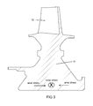
- FIG. 3 shows a cross section side view of an IBR with axial and hoop stress directions of the present invention.
- FIG. 4 shows a cross section side view of the IBR of the present invention with disk bore cooling holes and a circumferential channel.
- FIG. 5 shows a ceramic core used to form the disk bore cooling holes in the IBR of the present invention.
- FIG. 6 shows a cross section view of one of the elliptical shaped radial cooling holes having a major axis greater than a minor axis in the IBR of the present invention.
- FIG. 7 shows a cross section side view of a first embodiment of the IBR with cooling holes in a dishing shaped bore and the blade of the present invention.
- FIG. 8 shows a cross section side view of a second embodiment of the IBR with cooling holes in a projection of the disk bore and the blade of the present invention.
- FIG. 9 shows a cross section vide of a section of an engine with the cooling air supply path for the rotor disk of the present invention.
- the present invention is an IBR with cooling air supply holes passing through the disk or axial bore and opening into the bore where the bore cooling air supply holes have an elliptical cross sectional shape with a major axis perpendicular to the IBR bore axis and the minor axis parallel to the bore axis.
- This structure solves the hoop stress related LCF issue but introduces a very high axial compressive stress due to the stress concentration at the acute corner of the elliptical hole entrance.
- the axial compressive stress at the bore is caused by the blade and rim of the disk pulling outward and the disk bore restraining this pull.
- the center of the bore wants to move outward but is restrained causing the axial compressive stress. By dishing the bore inward, the axial compressive component of the stress is reduced and the hole entrance stress concentration yields a greater LCF life.
- Turbine rotor disks are designed to transmit torque from the rotor blades to the rotor shaft and to retain the blades in a stable condition.
- High rotational loads result in very high tensile bore stress in the tangential direction called hoop stress.
- the hoop stress and the axial stress are both indicated in FIG. 3 which occur near to where the radial cooling holes open into the axial bore of the IBR 10 .
- a decreased LCF lives are calculated at the location of the hole entrance. The LCF life can be increased at this location by forming the passages in an ellipse such that the less acute curve abuts the hoop direction and the more acute curve abuts the axial compressive load direction.
- the present invention introduces the cooling air to feed the blade cooling passages at the bore of the disk. This design precludes flooding the rim cavity with cooling air and essentially eliminates the leakage.
- FIG. 1 shows the IBR 10 of the present invention with a bore having an annular arrangement of cooling air entrance holes 18 .
- FIG. 2 shows a cross section cutaway view of the IBR of FIG. 1 with the radial cooling holes 13 and the circumferential channel 14 .
- the entrance holes 18 for the radial cooling holes 13 open into the axial disk bore of the IBR 10 .
- FIG. 3 shows a cross section view of the IBR with the hoop stress and the axial stress acting on the disk near an inner diameter of the axial bore of the IBR 10 due to rotation.
- the rotor blades 12 extend out from the disk 11 .
- FIG. 4 shows a cross section of the IBR with radial cooling air supply holes 13 that discharge into a circumferential channel 14 that is formed just below the platform of the blade.
- the radial supply holes 13 open in the bore at entrance holes 18 and discharge into the circumferential channel 14 .
- the disk bore has a dishing inward shape 15 .
- the radial supply holes 13 have an elliptical cross section shape as seen in FIG. 6 in which the major axis extends in a direction perpendicular to the axis of the bore and the minor axis of the hole 13 extends in a direction parallel to the axis of the bore. This shape reduces the stress in the region of the hole openings 18 .
- the circumferential channel 14 has a greater diameter than the radial cooling holes 13 .
- the stress levels in the disk are the greatest near to the axial bore. However, the stress levels are still quite high even in the section of the disk near to the blades.
- the radial holes 13 can have the elliptical cross sectional shape from the inlet opening 18 to the outlet discharge into the circumferential channel 14 .
- the radial cooling holes 13 could transition into a circular cross sectional shape toward the discharge into the circumferential channel 14 while still being within an acceptable level of stress.
- FIG. 5 shows a schematic view of a ceramic core that forms the radial supply holes 13 and the circumferential channel 14 .
- the ceramic core includes the radial supply hole forming pieces 21 and the circumferential channel forming piece 22 .
- the IBR is cast with the ceramic core of FIG. 5 to form the cooling air supply holes to the blades.
- the blade cooling holes 16 are formed.
- the blade cooling holes 16 can be formed by EDM or other drilling processes. The blade cooling holes 16 are formed after the IBR has been cast because of the small size of the blades.
- FIG. 8 shows a second embodiment of the IBR of the present invention.
- the bore in straight 16 but includes an annular projection 17 in which the cooling supply holes 13 open.
- the annular projection 17 is a 360 degree annular projection within the axial bore 16 .
- the stress field of the disk has high tangential stress at the bore and a much weaker axial compressive stress at the same location.
- the stress concentration is reduced at the high tangential stress locations.
- the size and number of the radial supply holes 13 can be tailored to the coolant flow requirements and the stress field in the rotor in order to achieve the required rotor life.
- the circumferential ring 21 of the ceramic core provides stability for the radial cooling supply forming pieces 22 during the casting process and a target to drill into when the cooling holes 16 in the blade are formed.
- the disk bore with the dishing inward shape 15 or the straight axial bore 15 with the projection 17 both provide improvement in the life of the IBR.
- the high stress concentrations occur at the cooling supply hole entrance and the elliptical shape of the holes 13 provide for reduced stress concentration in the tangential direction but the sharper acute corner of the ellipse yields a higher stress concentration.
- axial stress is small at this location, it combined with the stress concentration can drive the result concentrated stress higher than desired.
- the solution is to place the supply hole opening in a region where the axial stress is low, and this is achieved with the bowing of the bore or the projection on a straight bore.
- FIG. 9 shows a section of a gas turbine engine with the rotor blade cooling circuit described above with a cooling air supply circuit to deliver the cooling air from a compressor outlet to the radial cooling air holes 13 within the rotor 11 .
- FIG. 9 shows a compressor disk 31 , a combustor case 32 , and a combustor liner 33 , where compressed air discharged from the compressor flows through a diffuser and then flows around the combustor liner 33 where most of the compressed air flows into the combustion chamber and then through the first stage stator vanes 34 .
- Shaft 39 connects the compressor disk 31 to the turbine disk 11 and all three rotate as one unit.
- the angled nozzles 35 impact a swirl motion to the air before the air exits into a cavity 36 formed between the static combustor case 32 and the rotating shaft 39 .
- a labyrinth seal teeth 37 extends from the shaft 39 to form a seal with an underside surface of the static part of the stator vane 34 lower section.
Landscapes
- Engineering & Computer Science (AREA)
- Mechanical Engineering (AREA)
- General Engineering & Computer Science (AREA)
- Turbine Rotor Nozzle Sealing (AREA)
Abstract
An integrally bladed rotor with an axial bore having either an inward dishing shape or an axial straight shape with an annular inward projection in which radial cooling holes having an elliptical cross sectional shape are formed, where the radial cooling holes have an elliptical cross sectional shape with a major axis perpendicular to the axial bore in order to reduce stress near an inlet opening of the radial holes in order to increase the LCF life of the IBR. The radial cooling holes discharge into a circumferential channel that is connected to cooling holes extending in the rotor blades.
Description
This application is a CONTINUATION-IN-PART of U.S. patent application Ser. No. 15/190,703 filed on Jun. 23, 2016 and entitled INTEGRALLY BLADED ROTOR WITH BORE ENTRY COOLING HOLES.
None.
The present invention relates generally to a gas turbine engine, and more specifically to an integrally bladed rotor for a small gas turbine engine with blade cooling.
In a gas turbine engine, compressed air from a compressor is supplied to a combustor and burned with a fuel to produce a hot gas stream that is then passed through a turbine to produce mechanical energy. In an aero engine, the turbine drives both the compressor and a fan that produces the propulsion to power an aircraft.
The efficiency of the engine can be increased by passing a higher temperature gas stream through the turbine. However, the turbine inlet temperature is limited to the material properties of the turbine as well as the effectiveness of the turbine cooling. Compressed air is bled off from the compressor and passed through cooling circuits formed within stator vanes and rotor blades of the turbine to allow for higher turbine gas stream temperatures.
Turbine rotor blades are typically formed as a single piece with an airfoil extending from a root and platform to form the single piece rotor blade. The root typically has a dovetail or fir tree shape that is inserted into a slot form on an outside surface of a rotor. A small gas is thus formed between the blade root attachment and the rotor disk slot. In a large engine such as the type that powers a large aircraft, this gap is small compared to the size of the rotor. Thus, any leakage across the gap will be small compared to the flow passing through the rotor. However, for a small gas turbine engine such as those used to power a Unmanned Aero Vehicle (UAV), the gap is large when compared to the flow through the smaller rotor. For a gas turbine engine with a rotor with a diameter of less than four inches, any gap formed between the blade attachment and the rotor disk slot will be large and therefore the leakage flow across the rotor will be significant. For this reason, small gas turbine engines typically use an integrally bladed rotor (IBR) in which the rotor and the blades are all formed as a single piece to eliminate the gaps.
When cooling of airfoils is incorporated in a turbine engine, the non-cooling usage of the cooling air (leakage) is minimized as this represents a penalty to the engine cycle and reduces engine efficiency. Rather than routing cooling air to the blades past the rim of the disk (high leakage) it is desired to rout the cooling air from the bore of the disk, through the center of the disk, and to the blades. In the prior art, this approach has been avoided due to the reduction of the disk LCF (Low Cycle Fatigue) life caused by the hole entrance at the bore.
An Integrally Bladed Rotor (IBR) for a small gas turbine engine in which the rotor includes radial extending cooling supply holes that open within an axial bore of the disk and discharge into a circumferential extending cooling channel formed just below platforms of the blades. The radial cooling air supply holes have an elliptical cross sectional shape with a major axis aligned perpendicular to an axis of the axial bore and a minor axis aligned parallel to the axis of the axial bore so that stress levels within the disk are reduced to acceptable Low Cycle Fatigue (LCF) levels.
The radial cooling supply holes open into an axial bore having a curvature or dishing inward shape in order to locate the hole openings away from high stress areas. In another embodiment, the axial bore is formed straight but with projections in which the radial cooling holes open.
The IBR is formed with the radial cooling supply holes and the circumferential channel cast together, and then blade cooling holes are drilled using an EDM method because of the small size of the blades.
Compressed air for cooling of the first stage rotor blades is discharged from the compressor and flows around the combustor liner where some of the compressed air is bled off and passed through angled holes in a static part of the combustor case to provide the compressed air with a tangential flow component or swirling motion. The swirling compressed air is then passed into a rotating part of the rotor such that parasitic windage lose is minimized. The compressed air is then delivered to the inner bore of the rotor where the cooling air is further compressed due to rotation of the rotor before passing into the cooling channels of the blades.
The present invention is an IBR with cooling air supply holes passing through the disk or axial bore and opening into the bore where the bore cooling air supply holes have an elliptical cross sectional shape with a major axis perpendicular to the IBR bore axis and the minor axis parallel to the bore axis. This structure solves the hoop stress related LCF issue but introduces a very high axial compressive stress due to the stress concentration at the acute corner of the elliptical hole entrance. The axial compressive stress at the bore is caused by the blade and rim of the disk pulling outward and the disk bore restraining this pull. The center of the bore wants to move outward but is restrained causing the axial compressive stress. By dishing the bore inward, the axial compressive component of the stress is reduced and the hole entrance stress concentration yields a greater LCF life.
Turbine rotor disks are designed to transmit torque from the rotor blades to the rotor shaft and to retain the blades in a stable condition. High rotational loads result in very high tensile bore stress in the tangential direction called hoop stress. At the same time, there is an axial compressive stress in the bore of the disk. The hoop stress and the axial stress are both indicated in FIG. 3 which occur near to where the radial cooling holes open into the axial bore of the IBR 10. When passages are formed in the center of the disk passing from the bore to the rim for the purpose of supplying cooling air to the blades, a decreased LCF lives are calculated at the location of the hole entrance. The LCF life can be increased at this location by forming the passages in an ellipse such that the less acute curve abuts the hoop direction and the more acute curve abuts the axial compressive load direction.
Secondary cooling air leakage becomes more problematic as engine size is reduced. To mitigate this cooling air leakage, the present invention introduces the cooling air to feed the blade cooling passages at the bore of the disk. This design precludes flooding the rim cavity with cooling air and essentially eliminates the leakage.
The stress levels in the disk are the greatest near to the axial bore. However, the stress levels are still quite high even in the section of the disk near to the blades. Thus, the radial holes 13 can have the elliptical cross sectional shape from the inlet opening 18 to the outlet discharge into the circumferential channel 14. However, the radial cooling holes 13 could transition into a circular cross sectional shape toward the discharge into the circumferential channel 14 while still being within an acceptable level of stress.
When the IBR is in operation, the stress field of the disk has high tangential stress at the bore and a much weaker axial compressive stress at the same location. By forming the radial cooling holes 13 with the elliptical cross section shape, the stress concentration is reduced at the high tangential stress locations. The size and number of the radial supply holes 13 can be tailored to the coolant flow requirements and the stress field in the rotor in order to achieve the required rotor life. The circumferential ring 21 of the ceramic core provides stability for the radial cooling supply forming pieces 22 during the casting process and a target to drill into when the cooling holes 16 in the blade are formed.
The disk bore with the dishing inward shape 15 or the straight axial bore 15 with the projection 17 both provide improvement in the life of the IBR. The high stress concentrations occur at the cooling supply hole entrance and the elliptical shape of the holes 13 provide for reduced stress concentration in the tangential direction but the sharper acute corner of the ellipse yields a higher stress concentration. Although axial stress is small at this location, it combined with the stress concentration can drive the result concentrated stress higher than desired. The solution is to place the supply hole opening in a region where the axial stress is low, and this is achieved with the bowing of the bore or the projection on a straight bore.
Claims (13)
1. An integrally bladed rotor for a turbomachine comprising:
a rotor disk with a plurality of rotor blades extending from a rim of the integrally bladed rotor;
an axial bore;
a circumferential channel located in an outer section of the rotor disk near to the plurality of rotor blades;
a plurality of radial extending cooling holes each having an inlet opening in the axial bore and an outlet opening into the circumferential channel;
each of the plurality of rotor blades having a cooling air hole connected to the circumferential channel;
the radial extending cooling holes having a section of the holes with an elliptical cross section shape with a major axis greater than a minor axis; and,
the major axis is aligned perpendicular to a rotative axis of the axial bore.
2. The integrally bladed rotor of claim 1 , and further comprising:
the axial bore has a dishing inward shape with a continuous curvature from an inlet side of the axial bore to an outlet side.
3. The integrally bladed rotor of claim 1 , and further comprising:
the axial bore is a straight axial bore;
an annular projection within the straight axial bore; and,
the radial extending cooling holes pass through the annular projection and opening on an inner surface of the annular projection.
4. The integrally bladed rotor of claim 1 , and further comprising:
the circumferential channel has a circular cross sectional shape.
5. The integrally bladed rotor of claim 1 , and further comprising:
the circumferential channel has a greater diameter than the radial cooling holes.
6. The integrally bladed rotor of claim 1 , and further comprising:
the radial cooling holes have the elliptical cross sectional shape at least from the inlet opening to a section of the disk and a circular cross section shape opening into the circumferential channel.
7. The integrally bladed rotor of claim 1 , and further comprising:
the radial cooling holes have the elliptical cross sectional shape from the inlet opening to the discharge into the circumferential channel.
8. A turbine rotor disk comprising:
a rotor disk having an axial bore;
a plurality of rotor blades extending out from the rotor disk;
a circumferential channel formed within the rotor disk;
a plurality of radial extending cooling air holes having an inlet end opening into the axial bore and an outlet end opening into the circumferential channel;
each of plurality of rotor blades having an airfoil cooling passage connected to the circumferential channel;
the inlet opening of each of the radial extending cooling air supply holes having an elliptical cross sectional shape with a major axis greater than a minor axis; and,
the major axis for each of the plurality of inlets are perpendicular to a rotative axis of the axial bore.
9. The turbine rotor disk of claim 8 , and further comprising:
the rotor disk is an integrally bladed rotor.
10. The turbine rotor disk of claim 8 , and further comprising:
the axial bore is a straight axial bore;
an annular projection within the straight axial bore; and,
the radial extending cooling air holes pass through the annular projection and opening on an inner surface of the annular projection.
11. The turbine rotor disk of claim 8 , and further comprising:
the circumferential channel has a greater diameter than the radial cooling holes.
12. The turbine rotor disk of claim 8 , and further comprising:
the radial cooling holes have the elliptical cross sectional shape at least from the inlet opening of the axial bore and a circular cross section shape opening into the circumferential channel.
13. The turbine rotor disk of claim 8 , and further comprising:
the axial bore has an inward dishing shape around the inlet openings of each of the radial extending cooling air supply holes.
Priority Applications (1)
| Application Number | Priority Date | Filing Date | Title |
|---|---|---|---|
| US15/203,905 US10024170B1 (en) | 2016-06-23 | 2016-07-07 | Integrally bladed rotor with bore entry cooling holes |
Applications Claiming Priority (2)
| Application Number | Priority Date | Filing Date | Title |
|---|---|---|---|
| US201615190703A | 2016-06-23 | 2016-06-23 | |
| US15/203,905 US10024170B1 (en) | 2016-06-23 | 2016-07-07 | Integrally bladed rotor with bore entry cooling holes |
Related Parent Applications (1)
| Application Number | Title | Priority Date | Filing Date |
|---|---|---|---|
| US201615190703A Continuation-In-Part | 2016-06-23 | 2016-06-23 |
Publications (1)
| Publication Number | Publication Date |
|---|---|
| US10024170B1 true US10024170B1 (en) | 2018-07-17 |
Family
ID=62837126
Family Applications (1)
| Application Number | Title | Priority Date | Filing Date |
|---|---|---|---|
| US15/203,905 Active US10024170B1 (en) | 2016-06-23 | 2016-07-07 | Integrally bladed rotor with bore entry cooling holes |
Country Status (1)
| Country | Link |
|---|---|
| US (1) | US10024170B1 (en) |
Cited By (4)
| Publication number | Priority date | Publication date | Assignee | Title |
|---|---|---|---|---|
| US20180112531A1 (en) * | 2016-10-25 | 2018-04-26 | Pratt & Whitney Canada Corp. | Rotor disc with passages |
| US10794190B1 (en) | 2018-07-30 | 2020-10-06 | Florida Turbine Technologies, Inc. | Cast integrally bladed rotor with bore entry cooling |
| US11814991B1 (en) | 2022-07-28 | 2023-11-14 | General Electric Company | Turbine nozzle assembly with stress relief structure for mounting rail |
| US11885241B1 (en) * | 2022-07-28 | 2024-01-30 | General Electric Company | Turbine nozzle assembly with stress relief structure for mounting rail |
Citations (19)
| Publication number | Priority date | Publication date | Assignee | Title |
|---|---|---|---|---|
| US4312625A (en) * | 1969-06-11 | 1982-01-26 | The United States Of America As Represented By The Secretary Of The Air Force | Hydrogen cooled turbine |
| US4447188A (en) * | 1982-04-29 | 1984-05-08 | Williams International Corporation | Cooled turbine wheel |
| US4522562A (en) * | 1978-11-27 | 1985-06-11 | Societe Nationale D'etude Et De Construction De Moteurs D'aviation S.N.E.C.M.A. | Turbine rotor cooling |
| US5244345A (en) * | 1991-01-15 | 1993-09-14 | Rolls-Royce Plc | Rotor |
| US5317877A (en) * | 1992-08-03 | 1994-06-07 | General Electric Company | Intercooled turbine blade cooling air feed system |
| US5465780A (en) * | 1993-11-23 | 1995-11-14 | Alliedsignal Inc. | Laser machining of ceramic cores |
| US5860789A (en) * | 1996-03-19 | 1999-01-19 | Hitachi, Ltd. | Gas turbine rotor |
| US5961287A (en) * | 1997-09-25 | 1999-10-05 | United Technologies Corporation | Twin-web rotor disk |
| US6514038B2 (en) * | 1999-02-23 | 2003-02-04 | Hitachi, Ltd. | Turbine rotor, cooling method of turbine blades of the rotor and gas turbine with the rotor |
| US20050232780A1 (en) * | 2004-04-16 | 2005-10-20 | Rolls-Royce Plc | Turbine blisk |
| US7241111B2 (en) * | 2003-07-28 | 2007-07-10 | United Technologies Corporation | Contoured disk bore |
| US20080025843A1 (en) * | 2006-07-28 | 2008-01-31 | Philip Scope | Mounting disc |
| US20080295988A1 (en) * | 2006-02-09 | 2008-12-04 | General Electric Company | Method for removal of cores from niobium-based part, and related casting process |
| US7559745B2 (en) * | 2006-03-21 | 2009-07-14 | United Technologies Corporation | Tip clearance centrifugal compressor impeller |
| US7578656B2 (en) * | 2005-12-20 | 2009-08-25 | General Electric Company | High pressure turbine disk hub with reduced axial stress and method |
| US7585148B2 (en) * | 2004-03-17 | 2009-09-08 | Siemens Aktiengesellschaft | Non-positive-displacement machine and rotor for a non-positive-displacement machine |
| US20100326039A1 (en) * | 2008-02-28 | 2010-12-30 | Mitsubishi Heavy Industries, Ltd. | Gas turbine, disk, and method for forming radial passage of disk |
| US20130259685A1 (en) * | 2012-03-29 | 2013-10-03 | Narendra Are | Apparatus and method for purging a gas turbine rotor |
| US20140348664A1 (en) * | 2013-05-13 | 2014-11-27 | Honeywell International Inc. | Impingement-cooled turbine rotor |
-
2016
- 2016-07-07 US US15/203,905 patent/US10024170B1/en active Active
Patent Citations (19)
| Publication number | Priority date | Publication date | Assignee | Title |
|---|---|---|---|---|
| US4312625A (en) * | 1969-06-11 | 1982-01-26 | The United States Of America As Represented By The Secretary Of The Air Force | Hydrogen cooled turbine |
| US4522562A (en) * | 1978-11-27 | 1985-06-11 | Societe Nationale D'etude Et De Construction De Moteurs D'aviation S.N.E.C.M.A. | Turbine rotor cooling |
| US4447188A (en) * | 1982-04-29 | 1984-05-08 | Williams International Corporation | Cooled turbine wheel |
| US5244345A (en) * | 1991-01-15 | 1993-09-14 | Rolls-Royce Plc | Rotor |
| US5317877A (en) * | 1992-08-03 | 1994-06-07 | General Electric Company | Intercooled turbine blade cooling air feed system |
| US5465780A (en) * | 1993-11-23 | 1995-11-14 | Alliedsignal Inc. | Laser machining of ceramic cores |
| US5860789A (en) * | 1996-03-19 | 1999-01-19 | Hitachi, Ltd. | Gas turbine rotor |
| US5961287A (en) * | 1997-09-25 | 1999-10-05 | United Technologies Corporation | Twin-web rotor disk |
| US6514038B2 (en) * | 1999-02-23 | 2003-02-04 | Hitachi, Ltd. | Turbine rotor, cooling method of turbine blades of the rotor and gas turbine with the rotor |
| US7241111B2 (en) * | 2003-07-28 | 2007-07-10 | United Technologies Corporation | Contoured disk bore |
| US7585148B2 (en) * | 2004-03-17 | 2009-09-08 | Siemens Aktiengesellschaft | Non-positive-displacement machine and rotor for a non-positive-displacement machine |
| US20050232780A1 (en) * | 2004-04-16 | 2005-10-20 | Rolls-Royce Plc | Turbine blisk |
| US7578656B2 (en) * | 2005-12-20 | 2009-08-25 | General Electric Company | High pressure turbine disk hub with reduced axial stress and method |
| US20080295988A1 (en) * | 2006-02-09 | 2008-12-04 | General Electric Company | Method for removal of cores from niobium-based part, and related casting process |
| US7559745B2 (en) * | 2006-03-21 | 2009-07-14 | United Technologies Corporation | Tip clearance centrifugal compressor impeller |
| US20080025843A1 (en) * | 2006-07-28 | 2008-01-31 | Philip Scope | Mounting disc |
| US20100326039A1 (en) * | 2008-02-28 | 2010-12-30 | Mitsubishi Heavy Industries, Ltd. | Gas turbine, disk, and method for forming radial passage of disk |
| US20130259685A1 (en) * | 2012-03-29 | 2013-10-03 | Narendra Are | Apparatus and method for purging a gas turbine rotor |
| US20140348664A1 (en) * | 2013-05-13 | 2014-11-27 | Honeywell International Inc. | Impingement-cooled turbine rotor |
Cited By (6)
| Publication number | Priority date | Publication date | Assignee | Title |
|---|---|---|---|---|
| US20180112531A1 (en) * | 2016-10-25 | 2018-04-26 | Pratt & Whitney Canada Corp. | Rotor disc with passages |
| US10458242B2 (en) * | 2016-10-25 | 2019-10-29 | Pratt & Whitney Canada Corp. | Rotor disc with passages |
| US10794190B1 (en) | 2018-07-30 | 2020-10-06 | Florida Turbine Technologies, Inc. | Cast integrally bladed rotor with bore entry cooling |
| US11814991B1 (en) | 2022-07-28 | 2023-11-14 | General Electric Company | Turbine nozzle assembly with stress relief structure for mounting rail |
| US11885241B1 (en) * | 2022-07-28 | 2024-01-30 | General Electric Company | Turbine nozzle assembly with stress relief structure for mounting rail |
| US20240035388A1 (en) * | 2022-07-28 | 2024-02-01 | General Electric Company | Turbine nozzle assembly with stress relief structure for mounting rail |
Similar Documents
| Publication | Publication Date | Title |
|---|---|---|
| US6431820B1 (en) | Methods and apparatus for cooling gas turbine engine blade tips | |
| US8381533B2 (en) | Direct transfer axial tangential onboard injector system (TOBI) with self-supporting seal plate | |
| US6331097B1 (en) | Method and apparatus for purging turbine wheel cavities | |
| US6402471B1 (en) | Turbine blade for gas turbine engine and method of cooling same | |
| US8920128B2 (en) | Gas turbine engine cooling systems having hub-bleed impellers and methods for the production thereof | |
| US9091173B2 (en) | Turbine coolant supply system | |
| US6174135B1 (en) | Turbine blade trailing edge cooling openings and slots | |
| JP5108486B2 (en) | Plasma induced virtual turbine airfoil trailing edge extension | |
| US11655718B2 (en) | Blade with tip rail, cooling | |
| US9657642B2 (en) | Turbine sections of gas turbine engines with dual use of cooling air | |
| EP3036405B1 (en) | Component for a gas turbine engine, gas turbine engine comprising said component, and method of cooling a component of a gas turbine | |
| JP2008121673A (en) | Combined turbine cooling engine | |
| JP2002235502A (en) | Turbine blade for gas turbine engine and method for cooling the turbine blade | |
| JP2004332737A (en) | Method and apparatus for controlling tip clearance of a gas turbine engine rotor | |
| EP3428398A1 (en) | Airfoil and corresponding method of cooling a tip rail | |
| US10408075B2 (en) | Turbine engine with a rim seal between the rotor and stator | |
| US10024170B1 (en) | Integrally bladed rotor with bore entry cooling holes | |
| CN107084005A (en) | Gas turbine engine trailing edge injection holes | |
| CN104487657A (en) | Method for producing a guide vane and guide vane | |
| US20130318982A1 (en) | Turbine cooling apparatus | |
| EP2791472B2 (en) | Film cooled turbine component | |
| JP2019056366A (en) | Shield for turbine engine airfoil | |
| US20230059027A1 (en) | Method of cooling a turbine blade | |
| US10577945B2 (en) | Turbomachine rotor blade | |
| US20190003320A1 (en) | Turbomachine rotor blade |
Legal Events
| Date | Code | Title | Description |
|---|---|---|---|
| STCF | Information on status: patent grant |
Free format text: PATENTED CASE |
|
| FEPP | Fee payment procedure |
Free format text: ENTITY STATUS SET TO UNDISCOUNTED (ORIGINAL EVENT CODE: BIG.); ENTITY STATUS OF PATENT OWNER: LARGE ENTITY |
|
| MAFP | Maintenance fee payment |
Free format text: PAYMENT OF MAINTENANCE FEE, 4TH YEAR, LARGE ENTITY (ORIGINAL EVENT CODE: M1551); ENTITY STATUS OF PATENT OWNER: LARGE ENTITY Year of fee payment: 4 |
|
| MAFP | Maintenance fee payment |
Free format text: PAYMENT OF MAINTENANCE FEE, 8TH YEAR, LARGE ENTITY (ORIGINAL EVENT CODE: M1552); ENTITY STATUS OF PATENT OWNER: LARGE ENTITY Year of fee payment: 8 |