US10024014B1 - Nonfloating oil fence boom - Google Patents
Nonfloating oil fence boom Download PDFInfo
- Publication number
- US10024014B1 US10024014B1 US15/657,071 US201715657071A US10024014B1 US 10024014 B1 US10024014 B1 US 10024014B1 US 201715657071 A US201715657071 A US 201715657071A US 10024014 B1 US10024014 B1 US 10024014B1
- Authority
- US
- United States
- Prior art keywords
- section
- buoyant
- nonfloating
- boom
- oil fence
- Prior art date
- Legal status (The legal status is an assumption and is not a legal conclusion. Google has not performed a legal analysis and makes no representation as to the accuracy of the status listed.)
- Active - Reinstated
Links
Images


Classifications
-
- E—FIXED CONSTRUCTIONS
- E02—HYDRAULIC ENGINEERING; FOUNDATIONS; SOIL SHIFTING
- E02B—HYDRAULIC ENGINEERING
- E02B15/00—Cleaning or keeping clear the surface of open water; Apparatus therefor
- E02B15/04—Devices for cleaning or keeping clear the surface of open water from oil or like floating materials by separating or removing these materials
- E02B15/08—Devices for reducing the polluted area with or without additional devices for removing the material
- E02B15/0814—Devices for reducing the polluted area with or without additional devices for removing the material with underwater curtains
-
- Y—GENERAL TAGGING OF NEW TECHNOLOGICAL DEVELOPMENTS; GENERAL TAGGING OF CROSS-SECTIONAL TECHNOLOGIES SPANNING OVER SEVERAL SECTIONS OF THE IPC; TECHNICAL SUBJECTS COVERED BY FORMER USPC CROSS-REFERENCE ART COLLECTIONS [XRACs] AND DIGESTS
- Y02—TECHNOLOGIES OR APPLICATIONS FOR MITIGATION OR ADAPTATION AGAINST CLIMATE CHANGE
- Y02A—TECHNOLOGIES FOR ADAPTATION TO CLIMATE CHANGE
- Y02A20/00—Water conservation; Efficient water supply; Efficient water use
- Y02A20/20—Controlling water pollution; Waste water treatment
- Y02A20/204—Keeping clear the surface of open water from oil spills
Definitions
- NFO Fence Boom Nonfloating Oil Containment and Protection Boom
- responders can use NFO Fence Booms to contain spilled oil in a proximate location, and prevent migration of submerged oil from impacting nearby sensitive environments or other commercial interests.
- NFO Fence Booms can be placed to protect sensitive areas and deflect the oil into planned recovery locations. As with floating booms, this allows responders to use currents and the intrinsic heavy oil properties to aid in the spilled oil recovery and in protecting valued ecological and commercial assets.
- the NFO Fence Boom is designed to provide an effective seal with the seabed and a barrier to contain and redirect submerged oil for concentration and recovery.
- NFO Fence Booms are made using highly flexible but impermeable fabrics like the urethane and PVC coated nylon or poly scrim fabrics used in the manufacture of floating containment booms.
- Portions of the NFO Fence boom can also contain or be composed of adsorbent or absorbent water permeable materials to aide in the containment of spills and continuously work in heavy current flow situations.
- the NFO Fence Boom works in two planes to contain and redirect submerged oil.
- a horizontal section ballasted by chain pockets hugs the contours of the underwater floor and can be tucked into sand or rubble to limit oil seep under the boom.
- Grommet holes along the chain ballast pockets allow the boom to accommodate stakes driven into the underwater floor for additional anchoring security.
- a vertical section is joined to the horizontal section with an impermeable seam at a main chain ballast pocket.
- the vertical section has a buoyant section which causes only enough buoyancy to suspend the vertical section in an upright position and not raise the ballasted chain pockets or horizontal section from the seafloor during operation.
- the horizontal section extends at least from the main chain ballast pocket to a leading edge having a second chain ballast pocket, the leading edge being the closest part of the NFO fence boom to the heavy oil that is to be contained.
- the two chain ballast pockets specific horizontal configuration allows an impermeable seal to the underwater floor, thus submerged heavy oil is caught above the horizontal section and in the suspended vertical section while non-contaminated water can move easily over top of the NFO Fence Boom.
- NFO Fence Booms can be diver-deployed in ten—twenty meter sections that can be placed individually in overlapping chevron patterns to direct submerged oil flow or can be linked together to form a continuous subsea barrier to isolate and contain sunken oil at docks, berths, river sections, or other vessel grounding, wreck or pipeline break locations.
- linking mechanisms are well known in the art and can be composed of snaps, hook and loop fasteners, overlapping clamps, zippers, tied grommets, heat sealing, adhesives, or any combination thereof.
- overlapping sections containing grommets on linking sides of a NFO Fence boom section are both folded toward the leading edge and then zip tied or tied together.
- the horizontal section can extend from the main chain ballast pocket away from the leading edge, thus creating a tail edge that can comprise grommet holes or other well known structures to accept stakes and/or can be buried with sand, rocks or rubble to additionally secure the NFO Fence Boom in its stable underwater position. It is within the scope of the invention that the vertical section and horizontal section from the main chain ballast pocket to the leading edge are a single continuous sheet of fabric thus maximizing linked section sealing capabilities.
- NFO Fence Booms can be deployed by a boat in much longer sections to expedite deployment and recovery for large spill containment.
- the overall structure and support for the NFO Fence Boom is identical for either type of deployment and contain the same inventive concept. That inventive concept being a mobile fully submerged NFO fence boom structure that works in two planes to contain and redirect heavy or sinking oils along the underwater floor.
- the buoyant section allows only enough buoyant force to maintain the vertical section in an upright perpendicular position while maintaining the horizontal sections seal against the underwater floor.
- the entirety of the NFO Fence Boom being submerged underwater thus allowing tidal flow and current flow to pass over the NFO Fence Boom while trapping heavy sunken oil. It
- buoys with pre-calculated diameters in the buoyant section to cause such proper buoyancy for the depth and/or density of the local water and specific size of the NFO fence boom, thus allowing variation for salt and fresh water spills.
- buoys can be formed of PVC, foam, or any non-collapsible tube formed of material commonly used in the art. These characteristics provide for ease in installation and a secure seal at the seabed. Additionally the chain ballasts used can be linked together between sections thus providing a sturdy continuous chain to accept the forces required when deploying and/or retrieving the NFO Fence Boom.
- Additional straps can be used between the vertical section and horizontal section, or between the vertical section and the underwater floor to maintain the vertical sections stable upright configuration when positioned at locations with heavy flow. These straps can also be used to bind the top end of the vertical section to the leading edge of the horizontal section in a folded manner to allow easier handling during deployment and/or retrieval. Furthermore stiffening elements can be positioned every few feet or as desired on the horizontal section between the main chain ballast pocket and the second chain ballast pocket or along the vertical section from the bottom end to a top end.
- the stiffening elements can be a few mm thick piece of plastic or other torsional and longitudinally rigid material a couple inches wide that extends the entire length of the horizontal section, or any portion of the horizontal or vertical section deemed necessary for varying floor geometries.
- the stiffeners aid in maintaining the chain ballast pockets separation from each other and prevent twisting of the horizontal section as the NFO Fence Boom is sinking to the underwater floor during deployment. This allows for optimal speed while setting the NFO Fence Boom in its stable sealed upright configuration.
- FIG. 1 shows the NFO Fence Boom in its natural habitat, linked together beneath the surface of a body of water and abutting the underwater seafloor in the migrating path of a large bath of heavy sunken oil.
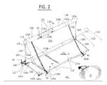
- FIG. 2 shows a 3D perspective view of the NFO Fence Booms two plane containing sealed barrier in complete detail.
- FIG. 3 a shows a side view of the NFO Fence Boom while in an upright perpendicular position on the underwater floor.
- FIG. 3 b shows a side view of the NFO Fence Boom while in a folded deployment/retrieval position
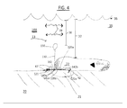
- FIG. 4 shows the NFO Fence boom in use where the sunken oils are actively contained by the NFO Fence Boom and the uncontaminated water is able to pass unrestricted above the buoyant section.
- a NFO Fence Boom 100 is shown with linked NFO Fence Boom sections 100 a - f .
- the NFO Fence boom 100 can be deployed into water 35 via the boat 30 off a spool 31 and/or with aid from a diver 33 in a flow path of a migrating heavy or sunken oil 22 which flows on an underwater floor 20 .
- the heavy oil 22 is at a depth 37 beneath a surface 36 of the water 35 .
- the NFO Fence Boom section 100 is comprised of a vertical section 110 , a horizontal section 120 and a buoyant section 130 .
- the vertical section 110 and horizontal section 120 are preferably composed of an impermeable poly coated fabric such as urethane or PVC coated nylon.
- the horizontal section 120 is comprised of a leading section 122 and a tail edge 121 .
- a main chain ballast pocket 140 a is located at a bottom end 110 b of vertical section 110 .
- the horizontal section 120 is impermeably sealed at a joint 102 to the vertical section 110 via heat welding.
- the vertical section 110 and the leading section 122 are a continuous length of fabric and the tail edge 121 is impermeably sealed at joint 102 to the main chain ballast pocket 140 a.
- the leading section 122 has a leading edge 122 a where a second chain ballast pocket 140 b is located.
- the chain ballast pockets 140 a - b contain a main chain ballast 141 a and a second chain ballast 141 b .
- the chain ballast pockets 140 a - b are formed by folding said poly coated fabric back onto itself and then heat welding or sewing the fold thus creating the pockets as is commonly done in the art. A common form of heat welding is radiofrequency welding and can be used to fabricate such pockets.
- the fabrics used in the vertical section 110 and horizontal section 120 are preferably impermeable fabrics such as polyurethane, or PVC coated nylons, additional types of fabrics that are also absorbent or adsorbent may be used, such fabrics are commonly known in the art.
- the buoyant section 130 can have multiple buoy pockets 130 a - d which are formed in the vertical section 110 using the same folding method as the chain ballast pockets 140 a - b and can be separated by sewing or heat welding at areas 131 a as needed.
- Each pocket has either a slit 32 or an air inlet hole 134 that allows inflation of each buoy pocket 130 a - d individually, or the entire buoyant section 130 can be inflated and deflated as a whole.
- a prefabricated buoy 131 can be integrally sealed into the buoyant section 130 a - d during manufacture, in such cases it may be desirable to only secure the buoys 131 into the pockets 130 a - d without completely sealing the pocket 130 a - d thus allowing water seepage to evacuate the buoy pockets 130 a - d upon retrieval of the NFO Fence Boom.
- the buoyant section 130 is engineered to create only enough buoyancy to maintain the vertical section 110 in an upright perpendicular position 13 , and not lift the horizontal section 120 , this is referred to as a proper buoyant force.
- the proper volume is pre-calculated at manufacture depending on the specific materials used, and more specifically depending on the mass and volume of the fabric, chain and/or buoys used for the entire vertical section 110 , main chain ballast 141 a , and buoyant section 130 which, overall, cause a sinking force on the vertical section 110 that allows the horizontal section 120 to abut the underwater floor 20 .
- a sinking force to proper buoyant force ratio is at least 2:1.
- the proper buoyant force is only half the magnitude of the vertical sections sinking force, and since the main chain ballast 141 a is located at the bottom 110 b of the vertical section 110 and creates the majority of the sinking force due to its massive nature compared to the fabrics, the vertical section 110 is upwardly stretched with buoyant tension and maintained in the upright perpendicular position 13 without lifting the bottom surface 120 b of the horizontal section 120 from the underwater floor 20 , as seen in FIGS. 2, 3 a and 4 .
- a sinking force to proper buoyant force ratio for determining a volume of the prefabricated buoys could be higher than 2:1 such as 3:1 or 4:1, doing so allows for quicker deployment and a respective increase in sealing strength against the underwater floor 20 .
- increasing the sinking force to proper buoyant force ratio should not go as far as to prevent the vertical section 110 from being maintained in the upright perpendicular position 13 at the installation depth 38 , which would oppose the main object of the present invention.
- the prefabricated buoys 131 are most preferably incompressible spheres of small diameter so as to aid in the storage of the NFO Fence Boom on a spool 31 , however other buoys may be used which are either long flexible incompressible tubes or short incompressible buoys known in the art that could easily wrap around said spool 31 . Furthermore, a wire, cable or rope could be coupled to the buoys 131 , inside the pockets 130 a - d.
- the leading section 122 along with the two chain ballast pockets 140 a - b are designed to sink the NFO Fence Boom 100 to the underwater floor 20 and thus create an impermeable seal 21 .
- the leading section 122 can also comprise stiffeners 115 which act as an aid in deploying the NFO Fence Boom 100 into the water 35 and neatly onto the underwater floor 20 to expedite the formation of the NFO Fence Booms impermeable seal 21 .
- the impermeable seal 21 is designed differently than any inventions on the market.
- the seal 21 is formed by the main chain ballast pocket 140 a containing a main ballast chain 141 a , and the second chain ballast pocket 140 b containing a second chain ballast 141 b wherein the chain ballast pockets and an entire bottom surface 120 b of the horizontal section 120 abut the underwater floor 20 .
- the chain ballast pockets 140 a - b and chain ballasts 141 a - b are linkable between each NFO Fence Boom section 100 a - f by means that include but are not limited to carabineers, eyelets, rope, hook and loop fasteners, bolts, cable, heat welds or anything commonly used in the art.
- each NFO Fence Boom 100 has overlapping sections 103 located at the linking sides 110 c - d and 122 c - d of the vertical section 110 and leading section 122 respectively. Additionally tail edge 121 comprises overlapping sections 103 at each linking side 121 c - d . These overlapping sections 103 comprise linking means such as grommets 104 which can be thread together with rope, zip ties or the like as is commonly done in the art. Overlapping sections could also be composed primarily of hook and loop fasteners, zippers, clamps, snaps, adhesives or heat welded plastics as are commonly used in the art.
- the NFO Fence Boom 100 is shown in an upright perpendicular position 13 . This is shown by the vertical section 110 being suspended by the buoyant section 130 at a perpendicular arrangement with respect to the horizontal section 120 .
- the NFO Fence Boom 100 comprises a strap 150 which is adjustable in nature, such as a nylon webbing strap or chain with a carabineer.
- the strap 150 can be used for multiple reasons, one is to aid the vertical section 110 from falling over when the oil 22 comes into contact with the NFO Fence Boom 100 , further more strap 150 can have anchor holes 142 in which an additional chain with anchor or stake 42 could be attached to thus providing a further support means to hold and contain the heavy oils 22 .
- leading section 122 it is desired for the leading section 122 to extend from the joint 102 a distance equal to the height of the vertical section 110 , thus creating an equally substaintial dual plane NFO Fence Boom. IF the leading section 122 is too short compared to the height of the vertical section 110 , the chances of the seal 21 to be broken are increased, thus it I essential to the present invention that at least the leading section 122 of the horizontal section 120 extends a distance at least half the height of the vertical section 110 and more preferably equal to the height of the vertical section 110 .
- FIG. 3 b Another use of strap 150 is shown in FIG. 3 b wherein the strap 150 is shortened thus causing the vertical section 110 to lay down against the leading section 122 to allow easier deployment and retrieval.
- This configuration is generally referred to as a folded position 12 .
- the buoyant section 130 is inflatable/deflatable, and thus in the folded position 12 the buoyant section 130 is not inflated to promote an easier deployment of the NFO Fence Boom 100 . This ensures an expedited proper seal 21 with the underwater floor 20 during diver and/or boat deployment . . .
- the buoyant section 130 should remain deflated until the entire bottom surface 120 b of horizontal section 120 is abutting the underwater floor 20 , said stakes 42 are placed into the underwater floor, and said strap 150 is extended to allow the vertical section 110 to be suspended in its upright perpendicular position 13 .
- a diver 33 can use his pneumatic hose 34 to inflate the buoyant section 130 to provide the optimal buoyant force that maintains the vertical section 110 in its upright perpendicular position 13 without allowing the horizontal section 120 or chain ballast sections 140 a - b from rising off the underwater floor 20 , thus the impenetrable seal 21 is effectively maintained.
- the heavy sunken oils 22 are contained by the NFO Fence Boom 100 in its upright perpendicular position 13 .
- the seal 21 is formed via the chain ballast 141 a - b and the entire bottom surface 120 b of the horizontal section 120 .
- the seal 21 is further strengthened by the sunken oils 22 as the oils cover the leading section 122 by applying pressure to a top side 120 a of horizontal section 120 thus preventing the leading edge 122 a from lifting and breaking the seal 21 .
- rocks or debris 43 are used to secure the tail edge 121 from moving or lifting.
- the stiffeners 115 provide support between the main chain ballast pocket 140 a and the second chain ballast pocket 140 b , thus forcing the chain ballasts 141 a - b to maintain a horizontal separation distance 47 and not become entwined with one another. Furthermore, the stiffeners 115 create a stronger seal 21 with the underwater floor 20 by maintaining a horizontal surface area 122 ′ which opposes a top surface 122 b of leading section 122 as it abuts the underwater floor 20 .
- This horizontal surface area 122 ′ has a frictional seal with the underwater floor 20 and is maximized when the entire surface area 122 ′ is expanded from the main chain ballast pocket 140 a to the leading edge 122 a and completely abuts the underwater floor 20 .
- main chain ballast 141 a can be a larger gauge chain and/or a more dense chain than the second chain ballast 141 b .
- These chains for example could be 1 ⁇ 4, 3 ⁇ 8, 1 ⁇ 2, 5 ⁇ 8, 3 ⁇ 4and/or 1 inch gauge chain, other sizes of chain or cable can also be used.
- the stakes 42 can be any suitable anchoring system well known in the art for varying underwater floor conditions, which include but are not limited to metal stakes, wood stakes, wide drag anchors, heavy weighted anchors, rocks, and/or chains or rope used to connect said stake 42 to the stakeholes 142 .
- the nonfloating oil 22 could be comprised of dilbit, group V oils, sinking oils, fuel oils, asphalt or the like.
- the stakeholes 142 are also shown in the drawings as 142 a and 142 b to show different useful positions along the NFO Fence Boom 100 .
- the amount of stakeholes 142 , 142 a - b can vary depending on the location to be installed.
- the stakeholes 142 , 142 a , 142 b are multipurpose and are used to bind the top end 110 a of the vertical section 110 to the leading edge 122 a as shown in FIG. 3 b , an generally disclosed as the folded position 12 as well as to attach stakes 42 to the vertical section 110 via chain or nylon, or rope as is commonly done in the art.
- stakeholes 142 a - b can be sewn or heat welded metal D rings that easily accept nylon webbing 150 or carabineers with chains attached thereto, this embodiment allows multiple support chains to be used to hold the vertical section 110 against the heavy oils 22 mass, or very rapid currents without compromising the impermeability of fabrics used.
- These stakeholes 142 a,b can be placed at additional points along the NFO Fence Boom 100 such as at the top end 110 a , bottom end 110 b , or linking ends 110 c - d of vertical section 110 and/or at or near the overlapping sections 103 of the vertical section 110 or horizontal section 120 .
- the above embodiments are used purely to describe the inventive concept and are not to be construed as a fully limiting disclosure.
- the main object of this invention is to overcome the following shortcomings of the prior art: the inability to maintain an impermeable seal with the underwater floor; the movement of fence booms due to tidal flow, river currents, wind currents, underwater currents, animal migration or the like; and the difficulties of sinking buoyed fences to the underwater floor.
- the main object of the present invention is to provide a NFO Fence boom 100 that creates and maintains an impermeable seal 21 with an underwater floor 20 to stop migrating heavy oils 22 at a depth 37 beneath the body of waters surface 36 which is easily deployable by boat 30 and/or diver 33 that is less subject to water currents 39 due to the depth 38 of the buoyant section 130 while in an upright perpendicular position 13 .
- the NFO Fence Boom 100 maintains said impermeable seal 21 in an innovative step using a combination of a horizontal section 120 having a main chain ballast 141 a , a leading edge 122 a , a vertical section 110 impermeably sealed at a joint 102 to a main chain ballast pocket 140 a of the horizontal section 120 , a buoyant section 130 that is adjustably inflated by either an inflatable air inlet 34 or by use of prefabricated buoys 131 of different diameters inserted through slit 32 to provide a proper buoyant force to maintain the vertical section 110 in an upright perpendicular position 13 without lifting the chain ballast 141 a horizontal section 120 or leading edge 122 a from the underwater floor 20 . It is essential that the buoyant section 130 is maintained at a depth 38 beneath the surface 36 thus allowing optimal unrestricted flow of uncontaminated water above the fence thus minimizing the current flow 39 against the NFO Fence Boom.
- Another main object of the present invention is to provide an additional second chain ballast 141 b to increase sealing ability.
- the NFO Fence Boom 100 maintains said impermeable seal 21 in an innovative step using the combination of a horizontal section 120 having a main chain ballast 141 a and a second chain ballast 141 b , a vertical section 110 impermeably sealed at a joint 102 to a main chain ballast pocket 140 a of the horizontal section 120 , a buoyant section 130 that is adjustably inflated by either an inflatable air inlet 34 or by use of prefabricated buoys 131 of different diameters inserted through slit 32 to provide a proper buoyant force to maintain the vertical section 110 in an upright perpendicular position 13 without lifting the chain ballasts 141 a - b or horizontal section 120 from the underwater floor 20 . It is essential that the buoyant section 130 is maintained at a depth 38 beneath the surface 36 thus allowing optimal unrestricted flow of uncontaminated water above the fence.
- the NFO Fence Boom 100 is easily deployed due to the main chain ballast 141 a and second chain ballast 141 b being designed to supply a sinking force that is greater than the buoyant force of the buoyant section 130 , both being adjustable for any water depth 38 or water density.
- a plurality of stiffeners 115 can be disposed along the horizontal section 120 to aid in expedited deployment of longer sections 100 a - f by preventing the chain ballasts 141 a - b from getting tangled together.
- the buoyant section 130 can be deflated during deployment to expedite the sinking and installation.
- the buoyant section 130 can be filled by inflation means that are common in the art.
- the leading edge 122 a is staked 42 or buried 43 in a similar fashion as the tail edge 121 .
- the main chain ballast 141 a has enough sinking force to maintain the horizontal section 120 against the underwater floor 20 , while the buoyant section 130 is supplied with a proper buoyancy to keep the vertical section 110 in the upright perpendicular position 13 while not lifting the main chain ballast 141 a off the underwater floor 20 thus maintaining seal 21 to contain or redirect oils 22 .
- the stiffening members 115 can be used in the same fashion, wherein a strap 150 binds a top end 110 a of the vertical section to the leading edge 122 a in a folded position 12 during deployment and thus the buoyant section 130 and main chain ballast 141 a do not become entangled allowing easier installation.
- each NFO Fence Boom section 100 can be placed in a pattern that better suits the installation location than a linked fence, such patterns can be V shaped, chevron patterns, stepped alignments, or aligned one behind another to catch large baths of or fast flowing sunken oils 22 .
- the NFO Fence Boom 100 can have multiple sections linked for each portion of the pattern to ensure a long enough seal to contain said oils 22 , such as 2-3 sections linked per side of a V, or per step.
- the method comprising deploying a NFO Fence Boom 100 ; the NFO Fence Boom 100 comprising a buoyant section 130 , a horizontal section 120 , a vertical section 110 , a main chain ballast pocket 140 a , a main chain ballast 141 a ; sinking the NFO Fence Boom 100 to an underwater floor 20 until the main chain ballast 141 a and horizontal section 120 are abutting the underwater floor 20 ; staking 42 , 43 the horizontal section 120 to the underwater floor 20 ; inflating 131 , 134 the buoyant section 130 until is supplies a proper buoyant force to maintain the vertical section 110 in an upright perpendicular position 13 while not lifting the main chain ballast 141 a or horizontal section 120 from the underwater floor 20 ; thus providing an impermeable seal 21 to contain or redirect heavy or sunken oils 22 .
- This method can include usage of straps
Landscapes
- Engineering & Computer Science (AREA)
- General Engineering & Computer Science (AREA)
- Environmental & Geological Engineering (AREA)
- Mechanical Engineering (AREA)
- Civil Engineering (AREA)
- Structural Engineering (AREA)
- Cleaning Or Clearing Of The Surface Of Open Water (AREA)
Abstract
Description
Claims (9)
Priority Applications (2)
| Application Number | Priority Date | Filing Date | Title |
|---|---|---|---|
| US15/657,071 US10024014B1 (en) | 2017-07-21 | 2017-07-21 | Nonfloating oil fence boom |
| CA3011522A CA3011522C (en) | 2017-07-21 | 2018-07-17 | Nonfloating oil fence boom |
Applications Claiming Priority (1)
| Application Number | Priority Date | Filing Date | Title |
|---|---|---|---|
| US15/657,071 US10024014B1 (en) | 2017-07-21 | 2017-07-21 | Nonfloating oil fence boom |
Publications (1)
| Publication Number | Publication Date |
|---|---|
| US10024014B1 true US10024014B1 (en) | 2018-07-17 |
Family
ID=62837106
Family Applications (1)
| Application Number | Title | Priority Date | Filing Date |
|---|---|---|---|
| US15/657,071 Active - Reinstated US10024014B1 (en) | 2017-07-21 | 2017-07-21 | Nonfloating oil fence boom |
Country Status (2)
| Country | Link |
|---|---|
| US (1) | US10024014B1 (en) |
| CA (1) | CA3011522C (en) |
Cited By (3)
| Publication number | Priority date | Publication date | Assignee | Title |
|---|---|---|---|---|
| CN110199786A (en) * | 2019-05-09 | 2019-09-06 | 广西壮族自治区农业科学院 | A kind of rice spiral shell symbiotic cultivation method based on green manure |
| US10753057B1 (en) * | 2019-04-11 | 2020-08-25 | Kenny Carter Sokolowski | Bottom boom |
| US20240229399A9 (en) * | 2021-02-24 | 2024-07-11 | Verderg Limited | Bouyancy-assisted weir |
Families Citing this family (1)
| Publication number | Priority date | Publication date | Assignee | Title |
|---|---|---|---|---|
| CN111231104A (en) * | 2020-01-17 | 2020-06-05 | 北京九州动脉隧道技术有限公司 | Segment prefabrication and sinking process for underwater construction |
Citations (5)
| Publication number | Priority date | Publication date | Assignee | Title |
|---|---|---|---|---|
| US4252461A (en) * | 1978-07-28 | 1981-02-24 | Pirelli Furlanis Applicazioni Idrauliche | Maneuverable dam |
| US5688075A (en) * | 1993-10-25 | 1997-11-18 | Gradek; Thomas | Boom system |
| US5984577A (en) * | 1997-06-18 | 1999-11-16 | Strong; William P. | Flotation flood wall |
| US20010048851A1 (en) * | 2000-05-04 | 2001-12-06 | Dreyer Harold B. | Containment/exclusion boom with bird deterrent |
| US6743367B2 (en) * | 2001-10-29 | 2004-06-01 | Gunderboom, Inc. | Boom curtain with expandable pleated panels, containment boom containing the same, and use thereof |
-
2017
- 2017-07-21 US US15/657,071 patent/US10024014B1/en active Active - Reinstated
-
2018
- 2018-07-17 CA CA3011522A patent/CA3011522C/en not_active Expired - Fee Related
Patent Citations (5)
| Publication number | Priority date | Publication date | Assignee | Title |
|---|---|---|---|---|
| US4252461A (en) * | 1978-07-28 | 1981-02-24 | Pirelli Furlanis Applicazioni Idrauliche | Maneuverable dam |
| US5688075A (en) * | 1993-10-25 | 1997-11-18 | Gradek; Thomas | Boom system |
| US5984577A (en) * | 1997-06-18 | 1999-11-16 | Strong; William P. | Flotation flood wall |
| US20010048851A1 (en) * | 2000-05-04 | 2001-12-06 | Dreyer Harold B. | Containment/exclusion boom with bird deterrent |
| US6743367B2 (en) * | 2001-10-29 | 2004-06-01 | Gunderboom, Inc. | Boom curtain with expandable pleated panels, containment boom containing the same, and use thereof |
Cited By (3)
| Publication number | Priority date | Publication date | Assignee | Title |
|---|---|---|---|---|
| US10753057B1 (en) * | 2019-04-11 | 2020-08-25 | Kenny Carter Sokolowski | Bottom boom |
| CN110199786A (en) * | 2019-05-09 | 2019-09-06 | 广西壮族自治区农业科学院 | A kind of rice spiral shell symbiotic cultivation method based on green manure |
| US20240229399A9 (en) * | 2021-02-24 | 2024-07-11 | Verderg Limited | Bouyancy-assisted weir |
Also Published As
| Publication number | Publication date |
|---|---|
| CA3011522A1 (en) | 2019-01-21 |
| CA3011522C (en) | 2021-05-18 |
Similar Documents
| Publication | Publication Date | Title |
|---|---|---|
| US10024014B1 (en) | Nonfloating oil fence boom | |
| US5102261A (en) | Floating containment boom | |
| US8348549B2 (en) | Method and apparatus for absorptive boom | |
| US12252852B2 (en) | Fence system and method of use | |
| US6848861B2 (en) | Y-panel anchoring system for boom installation | |
| CN108086267B (en) | A lightweight anti-fouling screen and its layout and construction method | |
| US20170233966A1 (en) | Integrated marine barrier | |
| KR101611209B1 (en) | Silt protector and method thereof | |
| US7497643B2 (en) | Artificial reef | |
| US4657433A (en) | Shoreline erosion control mat and method of use therefor | |
| US20150078825A1 (en) | System and Method for Building and Maintaining Stable Sand Beach and Shoreline Profiles and for Controlling Beach or Riparian Erosion | |
| US10753057B1 (en) | Bottom boom | |
| US4100746A (en) | Protected aquatic sports area | |
| CN203279654U (en) | Purse net for marine culture | |
| JP3823273B2 (en) | Float body sheet | |
| US6190088B1 (en) | Device for forming a sand body and method for the application thereof | |
| CA3128667C (en) | Bottom boom | |
| US20090297270A1 (en) | Artificial reef and a method of constructing an artificial reef | |
| CA2826175C (en) | Subsea crude oil and/or gas containment and recovery system and method | |
| US9284704B2 (en) | Device and method for keeping channels clear of silt | |
| JP2015218552A (en) | Sandpack, underwater structure, and construction method of underwater structure | |
| Watson | Scour in the North Sea | |
| RU2226586C2 (en) | Anti-erosion bed revetment and building method thereof | |
| US20180202121A1 (en) | Aquatic containment material and method of use | |
| US20040197149A1 (en) | Boom system for water filtration in shallow water |
Legal Events
| Date | Code | Title | Description |
|---|---|---|---|
| STCF | Information on status: patent grant |
Free format text: PATENTED CASE |
|
| FEPP | Fee payment procedure |
Free format text: MAINTENANCE FEE REMINDER MAILED (ORIGINAL EVENT CODE: REM.); ENTITY STATUS OF PATENT OWNER: MICROENTITY |
|
| LAPS | Lapse for failure to pay maintenance fees |
Free format text: PATENT EXPIRED FOR FAILURE TO PAY MAINTENANCE FEES (ORIGINAL EVENT CODE: EXP.); ENTITY STATUS OF PATENT OWNER: MICROENTITY |
|
| STCH | Information on status: patent discontinuation |
Free format text: PATENT EXPIRED DUE TO NONPAYMENT OF MAINTENANCE FEES UNDER 37 CFR 1.362 |
|
| FP | Lapsed due to failure to pay maintenance fee |
Effective date: 20220717 |
|
| PRDP | Patent reinstated due to the acceptance of a late maintenance fee |
Effective date: 20221203 |
|
| FEPP | Fee payment procedure |
Free format text: PETITION RELATED TO MAINTENANCE FEES FILED (ORIGINAL EVENT CODE: PMFP); ENTITY STATUS OF PATENT OWNER: MICROENTITY Free format text: PETITION RELATED TO MAINTENANCE FEES GRANTED (ORIGINAL EVENT CODE: PMFG); ENTITY STATUS OF PATENT OWNER: MICROENTITY Free format text: SURCHARGE, PETITION TO ACCEPT PYMT AFTER EXP, UNINTENTIONAL (ORIGINAL EVENT CODE: M3558); ENTITY STATUS OF PATENT OWNER: MICROENTITY |
|
| MAFP | Maintenance fee payment |
Free format text: PAYMENT OF MAINTENANCE FEE, 4TH YEAR, MICRO ENTITY (ORIGINAL EVENT CODE: M3551); ENTITY STATUS OF PATENT OWNER: MICROENTITY Year of fee payment: 4 |
|
| STCF | Information on status: patent grant |
Free format text: PATENTED CASE |
|
| MAFP | Maintenance fee payment |
Free format text: PAYMENT OF MAINTENANCE FEE, 8TH YEAR, MICRO ENTITY (ORIGINAL EVENT CODE: M3552); ENTITY STATUS OF PATENT OWNER: MICROENTITY Year of fee payment: 8 |