US10022225B2 - Self-adjusting tissue holder - Google Patents
Self-adjusting tissue holder Download PDFInfo
- Publication number
- US10022225B2 US10022225B2 US14/807,407 US201514807407A US10022225B2 US 10022225 B2 US10022225 B2 US 10022225B2 US 201514807407 A US201514807407 A US 201514807407A US 10022225 B2 US10022225 B2 US 10022225B2
- Authority
- US
- United States
- Prior art keywords
- tissue
- holding plate
- tissue holder
- holder
- holding
- Prior art date
- Legal status (The legal status is an assumption and is not a legal conclusion. Google has not performed a legal analysis and makes no representation as to the accuracy of the status listed.)
- Active, expires
Links
Images


Classifications
-
- A—HUMAN NECESSITIES
- A61—MEDICAL OR VETERINARY SCIENCE; HYGIENE
- A61F—FILTERS IMPLANTABLE INTO BLOOD VESSELS; PROSTHESES; DEVICES PROVIDING PATENCY TO, OR PREVENTING COLLAPSING OF, TUBULAR STRUCTURES OF THE BODY, e.g. STENTS; ORTHOPAEDIC, NURSING OR CONTRACEPTIVE DEVICES; FOMENTATION; TREATMENT OR PROTECTION OF EYES OR EARS; BANDAGES, DRESSINGS OR ABSORBENT PADS; FIRST-AID KITS
- A61F2/00—Filters implantable into blood vessels; Prostheses, i.e. artificial substitutes or replacements for parts of the body; Appliances for connecting them with the body; Devices providing patency to, or preventing collapsing of, tubular structures of the body, e.g. stents
- A61F2/02—Prostheses implantable into the body
- A61F2/24—Heart valves ; Vascular valves, e.g. venous valves; Heart implants, e.g. passive devices for improving the function of the native valve or the heart muscle; Transmyocardial revascularisation [TMR] devices; Valves implantable in the body
- A61F2/2472—Devices for testing
Definitions
- heart valve disease The overall prevalence of heart valve disease in the United States, adjusted to the 2000 population, was estimated at that time to be 2.5%, with about 99,000 heart valve operations yearly. By 2011, it was estimated that roughly four million people in the United States were diagnosed annually with a heart valve disorder. Often, the only solution for degenerated or calcified heart valves is replacement of the entire valve, which up to now has been either a bioprosthetic or mechanical valve.
- BPV bioprosthetic valve
- porcine aortic valves or bovine pericardium that has been chemically fixed, cross-linking the tissue and masking the antigens present in the xenogeneic materials.
- BPVs are predicted to last 10-15 years, which is a lower expectation than that of mechanical valves.
- all-cause mortality is lower for patients implanted with mechanical valves as compared to BPVs.
- the mechanical valve has been shown to be more durable and can be projected to last longer, the BPV is still the best choice for those patients who cannot be put on anticoagulant regimes.
- certain patient populations preferably receive certain valves. For example elderly patients (65 years and older) typically receive BPVs because of expected life span and the reduced chance for calcification, and younger patients/children receive mechanical valves due to the decreased number of expected replacements required.
- tissue engineering approaches have been developed that seek to make curative solutions for patients who are seeking long-term treatment of disease and tissue degeneration.
- the constructs that are being researched and tested will not simply compensate for the damaged tissue; the aim is to create living tissue that can be implanted into a human that will, from that point on, grow and remodel.
- a tissue engineered heart valve will resemble both the size and shape of the native valve; be durable and fully functioning with good hemodynamics; be non-immunogenic, non-inflammatory, non-thrombogenic, and non-obstructive; respond to mechanical and biological cues appropriately; grow in size with the recipient; and will adapt to changing conditions throughout the life of the recipient and valve.
- natural and synthetic heart valve tissue BHV and engineered tissue is generally subjected to multiple treatment regimes.
- xenograft valve tissue must be decellularized to remove the native cells prior to either testing or implant.
- mechanical testing by use of a conditioning system can be carried out to examine and alter tissue strength or to ensure suitable strength prior to implant. Seeding of natural or synthetic scaffolds can also be carried out in development of new valves and/or to encourage integration with a recipient's natural tissue following implantation.
- tissue has been common to secure valve tissue during the various treatment regimens by temporarily suturing or clipping the tissue to mounting rings.
- physically attaching the tissue to the holding device can damage the tissue and cause mechanical weakening of the tissue.
- securement systems generally do not provide a method for securing the tissue with a tight seal, and fluid leakage around the tissue during the treatment protocols can prevent effective conditioning and/or testing.
- the tissue characteristics can change during treatment. For instance decellularization can lead to a loss of tissue volume, and presently known systems do not account for the physical changes of the tissue associated with a volume loss.
- the tissue can become loose in/on the holder and/or leaks can form between the tissue and the holder as decellularization takes place.
- tissue holder that can effectively grip tissue during conditioning and/or testing.
- a heart valve tissue holder that can provide for totally hands-free and secure retention during multiple treatment regimens would be of great benefit for natural or synthetic heart valve tissue for research and development protocols as well as for implantation protocols.
- the tissue holder can be a heart valve tissue holder.
- the tissue holder can include a first holding plate and a second holding plate.
- the first holding plate has a first side and a second side and a primary opening that passes from the first side to the second side of the first holding plate.
- the second holding plate also has a first side and a second side and a primary opening that passes from the first side to the second side of the second holding plate.
- the first and second holding plates are alignable with one another such that upon alignment the second side of the first holding plate is adjacent to the first side of the second holding plate and the primary openings of the two holding plates align with one another.
- the tissue holder can also include a clamping mechanism. When tightened the clamping mechanism can apply a clamping force between the first side of the first holding plate and the second side of the second holding plate when the two holding plates are aligned with one another.
- the tissue holder can include a spring.
- the spring can be held between the clamping mechanism and either the first holding plate or the second holding plate. During use, the spring can maintain the clamping force between the two holding plates.
- a method can include locating a portion of a tissue on a surface of the first holding plate, for example on the second side of the first holding plate.
- the second holding plate can be aligned with the first holding plate such that the tissue portion is between the first holding plate and the second holding plate and the primary openings of the two holding plates are axially aligned.
- the clamping mechanism can then be tightened thereby gripping the tissue portion between the first and second holding plates.
- the spring of the tissue holder can serve to maintain the clamping pressure on the tissue portion, for instance following decellularization of the tissue.
- the tissue holder can be used to hold heart valve tissue with the tissue portion held between the holding plates being, e.g., a ventricular portion of a heart valve.
- the heart valve can be held within the aligned openings of the two holding plates and, when present, an aortic root of the heart valve can extend away from the heart valve.
- the tissue holder can optionally also include a support stand to support the aortic root.
- FIG. 1 is a schematic of a sectional perspective view of one embodiment of a tissue holder as disclosed herein.
- FIG. 2 illustrates several pieces of a disassembled tissue holder.
- FIG. 3 is an exploded view of the tissue holder of FIG. 1 .
- FIG. 4 illustrates several views of a lower casing piece of a tissue holder including a bottom view ( FIG. 4A ) a perspective view ( FIG. 4B ), a top view ( FIG. 4C ), a schematic bottom view ( FIG. 4D ) and a sectional side view ( FIG. 4E ).
- FIG. 5 illustrates a schematic top view ( FIG. 5A ) and a sectional view ( FIG. 5B ) of an upper casing piece of a tissue holder.
- FIG. 6 illustrates a tightening/temporary support tool for use with a device.
- FIG. 7 is a schematic of a perspective view of an assembled tissue holder.
- FIG. 8 is an image of an assembled tissue holder.
- FIG. 9 illustrates the placement of a tissue portion on one side of a holding plate.
- FIG. 10 illustrates the holding plate following location of the tissue portion on the holding plate.
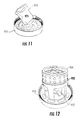
- FIG. 11 illustrates heart valve tissue gripped by a tissue holder.
- FIG. 12 illustrates an assembled device that is holding a heart valve and associated tissue.
- FIG. 13 illustrates the heart valve and associated tissue held in the device including a top view ( FIG. 13A ) and a bottom view ( FIG. 13B ).
- FIG. 14 illustrates a heart valve and associated tissue held in a device and coupled with a capping device.
- FIG. 15 illustrates a heart valve and associated tissue held in a treatment system for treating the tissue.
- FIG. 16 presents a top view of holding plates for a tissue holder as described herein.
- FIG. 17 presents a bottom view of the holding plates of FIG. 16 .
- FIG. 18 presents a perspective view of the holding plates of FIG. 16
- the present disclosure relates generally to tissue holders and, in one particular embodiment, to tissue holders for gripping natural or synthetic heart valves.
- the tissue holder can be self-adjusting with regard to pressure applied to the tissue gripped in the holder.
- the tissue holder can firmly grip a tissue sample throughout a procedure such as decellularization, seeding, or conditioning during which the physical characteristics (e.g., thickness) of the gripped tissue can change.
- the self-adjusting capability of the tissue holder can allow for the clamping force on the gripped tissue to be maintained and the tissue can be securely gripped in the holder throughout the procedure.
- tissue generally refers to an organization of one or more components that can support and interact with living cells.
- a tissue can be a natural tissue obtained from a natural source (e.g., human or animal-derived tissue), and can include natural structural components such as the structural proteins collagen, elastin, laminin, etc.
- a tissue can be a synthetic tissue, in which the structural components can include synthetically formed materials, e.g., hydrogel networks and fibers, etc. that can include synthetic polymers.
- a synthetic tissue can also include natural polymers, such as collagen, alginates, etc., that have been processed in some fashion to form the synthetic tissue.
- tissue can be the cells that are naturally present in a natural tissue or can be cells that are seeded on the natural or synthetic tissue for study and/or implantation in a living subject.
- tissue can refer to both the acellular structural scaffolding material as well as the structural scaffolding material in conjunction with cells.
- the self-adjusting characteristics of the tissue holder can provide a route to firmly grip a tissue during multiple different regimens.
- the tissue holder can be designed to fit with different treatment devices and systems.
- the tissue holder can be utilized in conjunction with a decellularization device and system during which the tissue gripped in the holder can be decellularized.
- the tissue holder can be moved to a cell seeding device and/or a bioreactor where the tissue gripped in the device can be subjected to strength testing, cell seeding etc.
- the tissue can be subjected to multiple different regimens in multiple different systems without removal from the tissue holder. This can provide for totally hands-free treatment of a tissue from initial development (in the case of a synthetic tissue) or from excisernent (in the case of a natural tissue) to either implantation or testing completion.
- tissue holder 10 is illustrated in the cut-away sectional view of FIG. 1 .
- the tissue holder includes a first holding plate 12 and a second holding plate 14 .
- the first holding plate 12 has a first side 11 and a second side 13 and the second holding plate 14 has a first side 9 and a second side 15 .
- the first holding plate 12 defines a primary opening 16 therethrough that passes from the first side 11 to the second side 13 of the first plate 12 .
- the second holding plate 14 defines a primary opening 17 therethrough that passes from the first side 9 to the second side 15 of the second plate 14 .
- the first and second plates 12 , 14 can be located adjacent to one another such that when they are aligned as shown in FIG. 1 , the primary openings 16 and 17 are axially aligned with one another.
- a tissue portion can be clamped between the adjacent sides of the two holding plates, e.g., between the second side 13 of the first plate 12 and the first side 9 of the second plate 14 .
- one or both of the plates can include one or more three dimensional features such as bumps, ridges, indentations, etc. on the side of the plate that will contact the tissue.
- the second side 13 of the first plate 12 can include a series of ridges 8 defined on the second side 13 .
- the second plate 14 can define a series of impressions 7 that can mate with the ridges 8 when the holding plates 12 , 14 are aligned. The mated features can increase the gripping force between the two plates.
- the second side 13 of the first plate 12 can define three-dimensional features such as ridges, bumps, etc. and the first side 9 of the second plate 14 can be substantially flat, such that the tissue sample is tightly held between the features of the first plate 12 and the flatter surface of the second plate 14 .
- Components of a tissue holder can be formed of polymeric materials, ceramic materials, metals, metal alloys, or any other formable material.
- the first plate 12 and the second plate 14 can both be formed of polymeric materials such as polyethylene (including high density polyethylene, ultrahigh molecular weight polyethylene, etc.), polysiloxanes, polyurethanes, polyvinyl chloride, polyacrylates, and so forth.
- Polymeric materials can be shaped according to known methodology, e.g., injection molding processes, 3-D printing, etc., to form one or more components of a tissue holder.
- the first plate 12 and the second plate can optionally be formed of other materials, however, such as ceramic materials (e.g., aluminum oxide, zirconia, etc.), or metals or metal alloys (e.g., stainless steel, cobalt alloys, titanium alloys, etc.) that can be molded or shaped according to standard methodology.
- ceramic materials e.g., aluminum oxide, zirconia, etc.
- metals or metal alloys e.g., stainless steel, cobalt alloys, titanium alloys, etc.
- the different components of a tissue holder can be formed of the same or different materials.
- the first holding plate 12 and the second holding plate 14 can both be formed of the same material, e.g., a polymeric material.
- the first holding plate 212 can be formed of a metal or metal alloy and the second holding plate 214 can be formed of a polymeric material. Any combination of suitable materials is encompassed herein.
- tissue holder can vary generally depending upon the tissue type that will be utilized with the holder. For instance, when a tissue holder is intended for use with heart valve tissue, the cross-sectional dimension of the tissue holder can generally be from about 1 inch to about 3 inches. The device cross section can be larger or smaller, however, as desired.
- the cross-sectional dimension of the primary openings 16 , 17 of the aligned plates 12 , 14 can vary, depending on the tissue type and size to be gripped by the holder.
- the aligned openings need not have the same cross sectional dimension as one another. For instance, as shown in FIG. 1 , the first and second holding plates 12 , 14 , are nested at the openings 16 , 17 , with the diameter of the opening 17 of the second plate 14 being smaller than the opening 16 of the first plate 12 .
- the device can also be provided with multiple plates that can provide various sizes and shapes of openings for treatment of different tissue types and sizes.
- the tissue holder of FIG. 2 includes a first plate 212 and a second plate 214 .
- the primary opening 217 of the second plate 214 is larger than the primary opening 216 of the first plate 212 .
- the size of the smaller of the two openings (e.g., opening 216 ) will be the limiting size for determining the size of the tissue gripped by the tissue holder.
- the holder can optionally include other first and second plates with larger or smaller openings or differently shaped openings that can be utilized alternatively to the first and/or second plates. For example, FIG. 16 , FIG. 17 , and FIG.
- FIG. 16 illustrates a top view of a first holding plate 612 and a second holding plate 614
- FIG. 17 presents a bottom view of the holding plates 612 , 614
- FIG. 18 presents perspective views of the holding plates 612 , 614 .
- the primary openings of these holding plates are not round.
- plates 612 , 614 include suture holes that can be used to further stabilize a tissue held by the plates 612 , 614 . Additional stabilization capabilities, such as suture holes, can be included in any holding plate of a system.
- the tissue holder can be used to grip a tissue of a different size or shape, for instance a mitral valve tissue segment.
- the diameter of the primary openings can generally be from about 0.5 inches to about 1.5 inches when considering use for heart valve tissues. This dimension can vary, however, for instance for other tissue types.
- the thickness of the first and second holding plates is generally not limited.
- the first and second plates can have a thickness from the first side to the second side of from about 0.05 inches to about 0.25 inches, or from about 0.1 inches to about 0.15 inches in some embodiments.
- the tissue holder 10 can also include a spring 20 that applies a force to the first plate 14 .
- a spring may be located in conjunction with the second plate 12 rather than the first plate 14 .
- the spring 20 is illustrated as a single coiled spring, but any type or number of springs can be utilized. For instance, a single or multiple leaf springs can be held against a plate of the holder or multiple coiled springs can be utilized, each held against a holding plate of the holder such that the spring exerts force on the plate. The force exerted on the plate by the spring can vary depending primarily on the tissue type to be held.
- the spring can exert a load of between about 5 pounds-force (lb f ) and about 100 lb f at the working surface.
- the tissue holder can be manually tightened or loosened as needed to maintain desired pressure on the tissue held between the holding plates.
- the spring can be formed of any material, e.g., any ceramic, polymeric, metal, or metal alloy as is generally known that can exert a force against one of the two holding plates by use of a clamping mechanism.
- the clamping mechanism can use any method of clamping, e.g., clips, screws, etc.
- the clamping mechanism is threaded and the gripping forces applied to a tissue held between the two plates can be increased and decreased as needed by tightening or loosening of the threaded clamping mechanism.
- the threaded clamping mechanism includes a first casing 22 and a second casing 24 .
- Several views of the first casing 22 are shown in FIG. 4 including a bottom perspective view ( FIG. 4A ), a side perspective view ( FIG. 4B ), a top perspective view ( FIG. 4C ), a bottom view ( FIG. 4D ) and a sectional side view ( FIG. 4E ).
- the first casing 22 includes a base 23 and a side 25 that is threaded on an interior surface, as shown.
- the first plate 12 can be seated in the first casing 22 with the first side 11 of the first plate 12 adjacent to the base 23 of the first casing 22 .
- the first casing can be formed of a material that can support and maintain the threads of the casing with repeated use, e.g., a ceramic, polymeric, metal or metal alloy.
- FIG. 5 illustrates a top view ( FIG. 5A ) and a sectional view ( FIG. 5B ) of the second casing 24 .
- Second casing 24 includes a surface 27 that, upon assembly of the tissue holder 10 will contact one end of the spring 20 as shown in FIG. 1 .
- the other end of the spring 20 abuts the second side 15 of the second plate 14 to apply pressure to the second plate 14 when compressed.
- the second casing 24 includes an external threaded side 26 that can partner with the internal threaded side 25 of the first casing 22 and function as a clamping mechanism for the tissue holder 10 when tightened together.
- a tissue can be firmly held between the first holding plate 12 and the second holding plate 14 .
- the spring 20 located between the second casing 24 and the second plate 14 applies pressure to a tissue held in the device once the first and second casings 22 , 24 are attached to one another at the threaded surfaces. This pressure can be maintained within a relatively narrow range and can be automatically adjusted by the spring even upon changes to the tissue clamped in the tissue holder.
- the first holding plate 212 can include a side 225 that has a threaded interior surface.
- the casing 224 is similar to that of the second casing 24 of FIG. 1 .
- the first holding plate 212 can be directly attached to the casing 224 via the paired threaded sides of the two components.
- the exterior threaded side 226 of the casing 224 can be paired to the interior threaded side 225 of the first plate 212 .
- the second holding plate 214 can be aligned with the first holding plate 212 with the primary openings 216 , 217 axially aligned and a tissue sample (not shown in FIG. 2 ), gripped between the first plate 212 and the second plate 214 .
- a spring ( 220 ) can be located between the second plate 214 and the casing 224 and upon tightening the casing 224 to the first plate 212 via the threads the tissue sample can be tightly gripped by the device.
- the first holding plate 212 , second holding plate 214 , and casing 224 include a series of flow openings 230 around the periphery of the components.
- the first casing 22 , first plate 12 , second plate 14 , and second casing 24 all include a series of flow openings 30 around the periphery of each component.
- the clamping mechanism need not include flow openings that match those of the holding plates. These flow openings can provide for flow across the tissue holder during a procedure.
- the flow openings 16 , 17 contain a tissue that either blocks flow completely or allows partial or periodic flow (e.g., a heart valve)
- the flow openings can be used to control pressure across the tissue.
- the flow openings 30 can be partially or fully aligned to allow a controllable flow through the openings or can be purposely misaligned to limit or prevent flow through the flow openings.
- the tissue holder can include an O-ring that can be assembled with the device (e.g., external to one of the casings) that can completely block flow through the flow openings.
- all flow through the device will be forced through the primary openings 16 , 17 and the tissue held there (e.g., through a heart valve) or alternatively, there can be no flow through the device, with a tissue held in the openings 16 , 17 blocking any flow through the primary openings 16 , 17 .
- the tissue holder can include a tool 60 as illustrated in FIG. 6 .
- the tool 60 can include a series of teeth 62 that can fit into the flow openings 30 of the casing 24 ( FIG. 7 ).
- the tool 60 can be, e.g., injection molded, 3D printed, etc., and can facilitate tightening of the clamping mechanism during assembly of the tissue holder.
- the tool 60 can support the tissue to be held in the device during assembly.
- the teeth 62 on the tool 60 can be designed with a predetermined height to selectively control which plates of the device are tightened by the tool.
- the teeth 62 can be relatively short, and during use the tool 60 can tighten only the upper casing 24 of a device as illustrated in FIG. 1 , FIG. 3 and FIG. 7 . In this embodiment, the tool will not place any circumferential forces on the tissue held between the first and second plates.
- the tool 60 can include longer teeth 62 that can reach through the flow holes of the upper casing and engage with the flow holes of the second plate 14 , which can place a torqueing force on the tissue held between the plates.
- the teeth 62 of the tool 60 can reach through the flow holes of both the first plate 14 and the second plate 12 and even through the flow holes of the first casing 22 to align the flow holes and/or to rotate the entire device 10 to a desired orientation in a secondary device (e.g., in a decellularization device).
- a secondary device e.g., in a decellularization device
- the tissue holder can be designed for gripping heart valve tissue.
- the tissue can be held such that the valve itself is suspended in or near the aligned primary openings of the first and second plates that are held together with the clamping mechanism and screw.
- a heart valve tissue segment may include at least a segment of a valve root (e.g. an aortic root in the case of an aortic valve) in conjunction with the heart valve.
- the tissue holder can include a stand and a containment aide for supporting the valve root.
- FIG. 7 illustrates one embodiment of a tissue holder 10 following assembly.
- the stand 32 can include multiple feet 31 that can be attachable to some other component of the tissue holder such as a casing or a holding plate.
- one or more feet 31 can be removably attachable to the second holding plate 14 of the tissue holder.
- the attachment between the stand 32 and the second holding plate 14 can be any suitable attachment, such as a ridged snap-lock, a luer-lock type of fitting, a key-hole fitting, or the like.
- the containment aide 34 can be separable from the stand 32 as shown in FIG. 2 and FIG. 3 or the two can be of unitary construction, as desired.
- the containment aide 34 can simply snap into place on the distal end of the stand 32 via a ridged snap lock, a key-hole fitting, or the like.
- the containment aide 34 can be adjustable on the stand 32 so as to accommodate different heights of a valve root.
- the containment aide 34 can include telescoping components that can be used to increase or decrease the height of the containment aide 34 .
- the containment aide 34 can include components for containing the tissue on/in the stand.
- the containment aide 34 can include holes that can be utilized to suture a tissue segment to the containment aide.
- a tissue segment can be clipped, tied, or otherwise contained on the aide and thus more securely held to the stand 32 .
- FIG. 3 presents an exploded image of the tissue holder 10 including the first casing 22 and the second casing 24 that can be attached to one another as a clamping mechanism for the device. Also shown is the first holding plate 14 and the second holding plate 12 between which a tissue portion can be secured, as well as a stand 32 and a containment aide 34 that can be utilized to hold a vessel portion, such as a valve root.
- FIG. 8 is another image of a tissue holder 810 following assembly.
- the tissue holder 810 includes a first casing 822 and a second casing 824 that are threaded together to form a clamping mechanism that holds the first holding plate (not visible in FIG. 8 ), the second holding plate 814 , and the spring (not visible in FIG. 8 ) there between.
- the tissue holder 810 also includes a stand 832 and a suture aide 834 that can be used to support a valve root of a section of heart valve tissue.
- FIG. 9 illustrates a method for associating a tissue with a tissue holder.
- a tissue section 870 can be spread over a surface of a first plate 812 of the holder. It should be understood that there is no requirement as to which of the two holding plates the tissue contacts first, the tissue will be applied to one surface of one of the plates and the second plate will then be aligned with the first plate such that the two primary openings are axially aligned.
- the tissue 870 has been spread over the surface of the plate 812 and is ready for the second plate to be aligned with the plate 812 .
- the tissue 870 includes a heart valve 872 that is located near or within the primary opening of the plate 812 .
- FIG. 11 illustrates the assembled tissue holder 910 with a section of heart valve tissue 970 in the holder.
- the valve root 975 has not yet been attached to a stand of the holder.
- the stand 932 and containment aide 934 have been attached to the tissue holder 910 and the valve root 975 is held inside of the stand 932 .
- the valve root 975 can then be attached to the containment aide 934 and more firmly held during subsequent testing/procedures.
- a section of the ventricle tissue (not visible in FIG. 11 or FIG. 12 ) is clamped between the plates for gripping the heart valve tissue 970 as discussed previously.
- FIG. 13 illustrates a top view ( FIG. 13A ) and a bottom view ( FIG. 13B ) of the assembled tissue holder 910 with the heart valve tissue 970 gripped in the holder.
- the heart valve 976 is accessible in the primary opening 916 of the first holding plate 912 from both the top via the valve root ( FIG. 13A ) and from the bottom ( FIG. 13B ).
- the tissue that is gripped in the tissue holder can be subjected to one or more treatment protocols and can be firmly gripped by the tissue holder throughout the protocols.
- the tissue holder can enable completely hands-free manipulation of a tissue from excisement or development to implantation.
- the engineered or excised tissue can be subjected to multiple treatment protocols that utilize multiple different devices and systems without the need to remove the tissue from the holder.
- the heart valve tissue 970 has been connected to a capping device 920 with an outflow tube that can be located in a decellularization chamber as illustrated in FIG. 15 .
- the tissue holder can be removed from the system and moved to a second system for further treatment of the tissue, and the tissue can remain in the holder without further handling of the tissue itself.
Landscapes
- Health & Medical Sciences (AREA)
- Cardiology (AREA)
- Oral & Maxillofacial Surgery (AREA)
- Transplantation (AREA)
- Engineering & Computer Science (AREA)
- Biomedical Technology (AREA)
- Heart & Thoracic Surgery (AREA)
- Vascular Medicine (AREA)
- Life Sciences & Earth Sciences (AREA)
- Animal Behavior & Ethology (AREA)
- General Health & Medical Sciences (AREA)
- Public Health (AREA)
- Veterinary Medicine (AREA)
- Prostheses (AREA)
Abstract
Description
Claims (12)
Priority Applications (2)
| Application Number | Priority Date | Filing Date | Title |
|---|---|---|---|
| US14/807,407 US10022225B2 (en) | 2014-07-23 | 2015-07-23 | Self-adjusting tissue holder |
| US16/010,889 US10660754B2 (en) | 2014-07-23 | 2018-06-18 | Self-adjusting tissue holder |
Applications Claiming Priority (2)
| Application Number | Priority Date | Filing Date | Title |
|---|---|---|---|
| US201462028064P | 2014-07-23 | 2014-07-23 | |
| US14/807,407 US10022225B2 (en) | 2014-07-23 | 2015-07-23 | Self-adjusting tissue holder |
Related Child Applications (1)
| Application Number | Title | Priority Date | Filing Date |
|---|---|---|---|
| US16/010,889 Division US10660754B2 (en) | 2014-07-23 | 2018-06-18 | Self-adjusting tissue holder |
Publications (2)
| Publication Number | Publication Date |
|---|---|
| US20160022420A1 US20160022420A1 (en) | 2016-01-28 |
| US10022225B2 true US10022225B2 (en) | 2018-07-17 |
Family
ID=55165771
Family Applications (2)
| Application Number | Title | Priority Date | Filing Date |
|---|---|---|---|
| US14/807,407 Active 2035-11-23 US10022225B2 (en) | 2014-07-23 | 2015-07-23 | Self-adjusting tissue holder |
| US16/010,889 Active 2035-08-10 US10660754B2 (en) | 2014-07-23 | 2018-06-18 | Self-adjusting tissue holder |
Family Applications After (1)
| Application Number | Title | Priority Date | Filing Date |
|---|---|---|---|
| US16/010,889 Active 2035-08-10 US10660754B2 (en) | 2014-07-23 | 2018-06-18 | Self-adjusting tissue holder |
Country Status (1)
| Country | Link |
|---|---|
| US (2) | US10022225B2 (en) |
Citations (38)
| Publication number | Priority date | Publication date | Assignee | Title |
|---|---|---|---|---|
| US5488789A (en) * | 1991-05-08 | 1996-02-06 | Nika Health Products Limited | Process and apparatus for the production of a heart valve prosthesis |
| US5607470A (en) * | 1995-05-01 | 1997-03-04 | Milo; Simcha | Suture rings for prosthetic heart valves |
| US5800531A (en) * | 1996-09-30 | 1998-09-01 | Baxter International Inc. | Bioprosthetic heart valve implantation device |
| US5823342A (en) * | 1997-11-14 | 1998-10-20 | Sulzer Carbomedics Inc. | Packaging for mitral or aortic heart valve device |
| US5846828A (en) | 1995-06-07 | 1998-12-08 | Advanced Tissue Sciences | Apparatus and method for sterilizing, seeding, culturing, storing, shipping, and testing tissue, synthetic, or mechanical heart valves orvalve segments |
| US5899937A (en) | 1997-03-05 | 1999-05-04 | Cryolife, Inc. | Pulsatile flow system for developing heart valves |
| US5976183A (en) * | 1998-01-05 | 1999-11-02 | Medical Carbon Research Institute, Llc | Sewing ring for heart valve prosthesis |
| US6121042A (en) | 1995-04-27 | 2000-09-19 | Advanced Tissue Sciences, Inc. | Apparatus and method for simulating in vivo conditions while seeding and culturing three-dimensional tissue constructs |
| US6126007A (en) | 1998-12-30 | 2000-10-03 | St. Jude Medical, Inc. | Tissue valve holder |
| US6214043B1 (en) * | 1995-05-24 | 2001-04-10 | St. Jude Medical, Inc. | Releasable hanger for heart valve prosthesis low profile holder |
| US6383732B1 (en) | 1999-02-11 | 2002-05-07 | Crosscart, Inc. | Method of preparing xenograft heart valves |
| US6409758B2 (en) | 2000-07-27 | 2002-06-25 | Edwards Lifesciences Corporation | Heart valve holder for constricting the valve commissures and methods of use |
| US6432712B1 (en) | 1999-11-22 | 2002-08-13 | Bioscience Consultants, Llc | Transplantable recellularized and reendothelialized vascular tissue graft |
| US6652583B2 (en) | 2000-04-07 | 2003-11-25 | Rhode Island Hospital | Cardiac valve replacement |
| US6881569B2 (en) | 2002-01-25 | 2005-04-19 | Children's Medical Center Corporation | Apparatus and method for evaluating tissue engineered biological material |
| US6952814B2 (en) | 2002-11-20 | 2005-10-04 | Sun Microsystems Inc. | Method and apparatus for establishment of a die connection bump layout |
| US6964682B2 (en) | 2000-12-21 | 2005-11-15 | Edwards Lifesciences Corporation | Heart valve holder that resist suture looping |
| US6966925B2 (en) | 2000-12-21 | 2005-11-22 | Edwards Lifesciences Corporation | Heart valve holder and method for resisting suture looping |
| US20060015177A1 (en) * | 2004-07-19 | 2006-01-19 | St. Jude Medical, Inc. | Heart valve support and lid liner system and methods |
| US7063942B2 (en) | 2000-10-06 | 2006-06-20 | Victor Krstec | System and method to simulate hemodynamics |
| US20060136052A1 (en) * | 2004-12-16 | 2006-06-22 | Valvexchange Inc. | Cardiovascular valve assembly |
| US7112218B2 (en) | 1999-11-22 | 2006-09-26 | Cytograft Tissue Engineering, Inc. | Tissue engineered blood vessels and apparatus for their manufacture |
| US7378271B2 (en) | 2001-06-25 | 2008-05-27 | Augustinus Bader | Device for pressurized perfusion especially for culturing and/or treating cells |
| US7439057B2 (en) | 2004-11-16 | 2008-10-21 | La Jolla Bioengineering Institute | Convective flow tissue assembly |
| US7498412B2 (en) | 2001-08-17 | 2009-03-03 | National Cheng Kung University | Process for preparing porous collagen matrix from connective tissue |
| US7504258B2 (en) | 2001-12-11 | 2009-03-17 | Cytograft Tissue Engineering, Inc. | Tissue engineered cellular sheets, methods of making and use thereof |
| US7691046B2 (en) | 2004-01-08 | 2010-04-06 | Pumpworks, Inc. | Nondestructive fluid transfer device |
| US7754232B2 (en) | 2003-05-22 | 2010-07-13 | The University Of Leeds | Ultrasonic modification of soft tissue matrices |
| US7753840B2 (en) | 2002-11-26 | 2010-07-13 | Clemson University | Tissue material process for forming bioprosthesis |
| US7851200B2 (en) | 2003-11-01 | 2010-12-14 | More Robert B | Bioreactor for growing engineered tissue |
| US7871367B2 (en) | 2001-08-31 | 2011-01-18 | Ams Research Corporation | Surgical articles for placing an implant about a tubular tissue structure and methods |
| US20110167603A1 (en) * | 2008-09-12 | 2011-07-14 | Ivan Vesely | Valve assembly with exchangeable valve member and a tool set for exchanging the valve member |
| US8230717B2 (en) | 2008-12-18 | 2012-07-31 | Ethicon, Inc. | Paravalvular leak test apparatus and method |
| US20120290079A1 (en) * | 2011-05-12 | 2012-11-15 | Edwards Lifesciences Corporation | Mitral heart valve holder and storage system |
| US8399243B2 (en) | 2005-02-17 | 2013-03-19 | Universitaet Zuerich | Method of manufacturing a tissue-engineered prosthesis |
| US8491457B2 (en) | 2005-03-11 | 2013-07-23 | Wake Forest University Health Services | Tissue engineered blood vessels |
| US8609415B2 (en) | 2008-02-01 | 2013-12-17 | Technische Universiteit Eindhoven | Method for manufacturing a tissue-engineered construct |
| US20140371842A1 (en) * | 2013-06-12 | 2014-12-18 | Edwards Lifesciences Corporation | Cardiac implant with integrated suture fasteners |
Family Cites Families (1)
| Publication number | Priority date | Publication date | Assignee | Title |
|---|---|---|---|---|
| KR100313248B1 (en) | 1999-12-14 | 2001-11-07 | 구본준, 론 위라하디락사 | Color Filter |
-
2015
- 2015-07-23 US US14/807,407 patent/US10022225B2/en active Active
-
2018
- 2018-06-18 US US16/010,889 patent/US10660754B2/en active Active
Patent Citations (45)
| Publication number | Priority date | Publication date | Assignee | Title |
|---|---|---|---|---|
| US5488789A (en) * | 1991-05-08 | 1996-02-06 | Nika Health Products Limited | Process and apparatus for the production of a heart valve prosthesis |
| US6121042A (en) | 1995-04-27 | 2000-09-19 | Advanced Tissue Sciences, Inc. | Apparatus and method for simulating in vivo conditions while seeding and culturing three-dimensional tissue constructs |
| US5607470A (en) * | 1995-05-01 | 1997-03-04 | Milo; Simcha | Suture rings for prosthetic heart valves |
| US6214043B1 (en) * | 1995-05-24 | 2001-04-10 | St. Jude Medical, Inc. | Releasable hanger for heart valve prosthesis low profile holder |
| US5846828A (en) | 1995-06-07 | 1998-12-08 | Advanced Tissue Sciences | Apparatus and method for sterilizing, seeding, culturing, storing, shipping, and testing tissue, synthetic, or mechanical heart valves orvalve segments |
| US5800531A (en) * | 1996-09-30 | 1998-09-01 | Baxter International Inc. | Bioprosthetic heart valve implantation device |
| US5899937A (en) | 1997-03-05 | 1999-05-04 | Cryolife, Inc. | Pulsatile flow system for developing heart valves |
| US5823342A (en) * | 1997-11-14 | 1998-10-20 | Sulzer Carbomedics Inc. | Packaging for mitral or aortic heart valve device |
| US5976183A (en) * | 1998-01-05 | 1999-11-02 | Medical Carbon Research Institute, Llc | Sewing ring for heart valve prosthesis |
| US6126007A (en) | 1998-12-30 | 2000-10-03 | St. Jude Medical, Inc. | Tissue valve holder |
| US6383732B1 (en) | 1999-02-11 | 2002-05-07 | Crosscart, Inc. | Method of preparing xenograft heart valves |
| US7112218B2 (en) | 1999-11-22 | 2006-09-26 | Cytograft Tissue Engineering, Inc. | Tissue engineered blood vessels and apparatus for their manufacture |
| US6432712B1 (en) | 1999-11-22 | 2002-08-13 | Bioscience Consultants, Llc | Transplantable recellularized and reendothelialized vascular tissue graft |
| US7744526B2 (en) | 1999-11-22 | 2010-06-29 | Cytograft Tissue Engineering, Inc. | Bioreactor for the manufacture of tissue engineered blood vessels |
| US7179287B2 (en) | 1999-11-22 | 2007-02-20 | Bioscience Consultants | Bioreactor mediated recellularization of natural and tissue engineered vascular grafts |
| US6652583B2 (en) | 2000-04-07 | 2003-11-25 | Rhode Island Hospital | Cardiac valve replacement |
| US7645568B2 (en) | 2000-06-01 | 2010-01-12 | Aperion Biologics, Inc. | Xenograft heart valves |
| US6409758B2 (en) | 2000-07-27 | 2002-06-25 | Edwards Lifesciences Corporation | Heart valve holder for constricting the valve commissures and methods of use |
| US7819915B2 (en) * | 2000-07-27 | 2010-10-26 | Edwards Lifesciences Corporation | Heart valve holders and handling clips therefor |
| US6702852B2 (en) | 2000-07-27 | 2004-03-09 | Edwards Lifesciences Corporation | Method for retrofitting a heart valve holder |
| US7063942B2 (en) | 2000-10-06 | 2006-06-20 | Victor Krstec | System and method to simulate hemodynamics |
| US6966925B2 (en) | 2000-12-21 | 2005-11-22 | Edwards Lifesciences Corporation | Heart valve holder and method for resisting suture looping |
| US6964682B2 (en) | 2000-12-21 | 2005-11-15 | Edwards Lifesciences Corporation | Heart valve holder that resist suture looping |
| US7658763B2 (en) | 2000-12-21 | 2010-02-09 | Edwards Lifesciences Corporation | Heart valve holder and method for resisting suture looping |
| US7378271B2 (en) | 2001-06-25 | 2008-05-27 | Augustinus Bader | Device for pressurized perfusion especially for culturing and/or treating cells |
| US7498412B2 (en) | 2001-08-17 | 2009-03-03 | National Cheng Kung University | Process for preparing porous collagen matrix from connective tissue |
| US7871367B2 (en) | 2001-08-31 | 2011-01-18 | Ams Research Corporation | Surgical articles for placing an implant about a tubular tissue structure and methods |
| US8308629B2 (en) | 2001-08-31 | 2012-11-13 | Ams Research Corporation | Surgical articles for placing an implant about a tubular tissue structure and methods |
| US7504258B2 (en) | 2001-12-11 | 2009-03-17 | Cytograft Tissue Engineering, Inc. | Tissue engineered cellular sheets, methods of making and use thereof |
| US6881569B2 (en) | 2002-01-25 | 2005-04-19 | Children's Medical Center Corporation | Apparatus and method for evaluating tissue engineered biological material |
| US6952814B2 (en) | 2002-11-20 | 2005-10-04 | Sun Microsystems Inc. | Method and apparatus for establishment of a die connection bump layout |
| US7753840B2 (en) | 2002-11-26 | 2010-07-13 | Clemson University | Tissue material process for forming bioprosthesis |
| US7754232B2 (en) | 2003-05-22 | 2010-07-13 | The University Of Leeds | Ultrasonic modification of soft tissue matrices |
| US7851200B2 (en) | 2003-11-01 | 2010-12-14 | More Robert B | Bioreactor for growing engineered tissue |
| US7691046B2 (en) | 2004-01-08 | 2010-04-06 | Pumpworks, Inc. | Nondestructive fluid transfer device |
| US20060015177A1 (en) * | 2004-07-19 | 2006-01-19 | St. Jude Medical, Inc. | Heart valve support and lid liner system and methods |
| US7439057B2 (en) | 2004-11-16 | 2008-10-21 | La Jolla Bioengineering Institute | Convective flow tissue assembly |
| US20060136052A1 (en) * | 2004-12-16 | 2006-06-22 | Valvexchange Inc. | Cardiovascular valve assembly |
| US8399243B2 (en) | 2005-02-17 | 2013-03-19 | Universitaet Zuerich | Method of manufacturing a tissue-engineered prosthesis |
| US8491457B2 (en) | 2005-03-11 | 2013-07-23 | Wake Forest University Health Services | Tissue engineered blood vessels |
| US8609415B2 (en) | 2008-02-01 | 2013-12-17 | Technische Universiteit Eindhoven | Method for manufacturing a tissue-engineered construct |
| US20110167603A1 (en) * | 2008-09-12 | 2011-07-14 | Ivan Vesely | Valve assembly with exchangeable valve member and a tool set for exchanging the valve member |
| US8230717B2 (en) | 2008-12-18 | 2012-07-31 | Ethicon, Inc. | Paravalvular leak test apparatus and method |
| US20120290079A1 (en) * | 2011-05-12 | 2012-11-15 | Edwards Lifesciences Corporation | Mitral heart valve holder and storage system |
| US20140371842A1 (en) * | 2013-06-12 | 2014-12-18 | Edwards Lifesciences Corporation | Cardiac implant with integrated suture fasteners |
Non-Patent Citations (77)
Also Published As
| Publication number | Publication date |
|---|---|
| US10660754B2 (en) | 2020-05-26 |
| US20180296342A1 (en) | 2018-10-18 |
| US20160022420A1 (en) | 2016-01-28 |
Similar Documents
| Publication | Publication Date | Title |
|---|---|---|
| US11617587B2 (en) | Clamp | |
| CN110740712B (en) | Crimping device for loading stents and prosthetic heart valves | |
| US11331188B2 (en) | Adjustable artificial chordae tendineae fixing assembly and an implanting method thereof | |
| US4693715A (en) | Artificial cornea | |
| US6319280B1 (en) | Prosthetic ring holder | |
| CN107427607B (en) | Methods, devices and systems for processing pericardial tissue | |
| US6699283B2 (en) | Heart valve with rectangular orifice | |
| CN108143540B (en) | Dressing support assembly for ocular surface and method of securing same | |
| US9974646B2 (en) | Keratoprosthesis, and system and method of corneal repair using same | |
| CN111671547A (en) | Valve clamp with cover and valve clamp system | |
| JPWO2006070628A1 (en) | Intraocular lens implantation device | |
| GB2083751A (en) | Prosthetic device positioning apparatus | |
| CN101715334A (en) | Corneal implant and method and system for placement | |
| JP2018519885A (en) | Morse taper protective sleeve | |
| CN109481101A (en) | A kind of anterior approach self-retaining artificial vertebral body | |
| CN113749830A (en) | A 3D printed porous interbody cage | |
| US20140330374A1 (en) | Implanting oversized objects into surgical beds | |
| US10660754B2 (en) | Self-adjusting tissue holder | |
| CN106232051A (en) | Dental Implant barrier film | |
| US11338067B2 (en) | Synthetic prosthesis for use in osteo-odonto-keratoprosthesis (OOKP) surgery | |
| US11446137B2 (en) | Flexible keratoprosthesis devices and uses thereof | |
| CN113662713B (en) | Valve backflow blocking device | |
| CN105997294A (en) | Repair system and repair method applied in craniocerebral operation | |
| US20120283827A1 (en) | Ossicular Prosthesis with Stabilizer and Method of Use with Intact Stapes | |
| US20110060406A1 (en) | Heart valve |
Legal Events
| Date | Code | Title | Description |
|---|---|---|---|
| AS | Assignment |
Owner name: CLEMSON UNIVERSITY, SOUTH CAROLINA Free format text: ASSIGNMENT OF ASSIGNORS INTEREST;ASSIGNORS:SIERAD, LESLIE;PASCAL, RICHARD, III;DEBORDE, CHRIS;AND OTHERS;SIGNING DATES FROM 20140806 TO 20140808;REEL/FRAME:036166/0337 |
|
| AS | Assignment |
Owner name: NATIONAL INSTITUTES OF HEALTH (NIH), U.S. DEPT. OF Free format text: CONFIRMATORY LICENSE;ASSIGNOR:CLEMSON UNIVERSITY;REEL/FRAME:036607/0168 Effective date: 20150910 |
|
| AS | Assignment |
Owner name: CLEMSON UNIVERSITY RESEARCH FOUNDATION, SOUTH CARO Free format text: ASSIGNMENT OF ASSIGNORS INTEREST;ASSIGNOR:CLEMSON UNIVERSITY;REEL/FRAME:039185/0827 Effective date: 20160606 |
|
| AS | Assignment |
Owner name: CLEMSON UNIVERSITY RESEARCH FOUNDATION, SOUTH CARO Free format text: ASSIGNMENT OF ASSIGNORS INTEREST;ASSIGNOR:CLEMSON UNIVERSITY;REEL/FRAME:039360/0407 Effective date: 20160606 |
|
| STCF | Information on status: patent grant |
Free format text: PATENTED CASE |
|
| MAFP | Maintenance fee payment |
Free format text: PAYMENT OF MAINTENANCE FEE, 4TH YR, SMALL ENTITY (ORIGINAL EVENT CODE: M2551); ENTITY STATUS OF PATENT OWNER: SMALL ENTITY Year of fee payment: 4 |
|
| MAFP | Maintenance fee payment |
Free format text: PAYMENT OF MAINTENANCE FEE, 8TH YR, SMALL ENTITY (ORIGINAL EVENT CODE: M2552); ENTITY STATUS OF PATENT OWNER: SMALL ENTITY Year of fee payment: 8 |