US10022006B1 - Clamping support assembly - Google Patents
Clamping support assembly Download PDFInfo
- Publication number
- US10022006B1 US10022006B1 US15/660,580 US201715660580A US10022006B1 US 10022006 B1 US10022006 B1 US 10022006B1 US 201715660580 A US201715660580 A US 201715660580A US 10022006 B1 US10022006 B1 US 10022006B1
- Authority
- US
- United States
- Prior art keywords
- tab
- finger
- central portion
- facing surface
- hook
- Prior art date
- Legal status (The legal status is an assumption and is not a legal conclusion. Google has not performed a legal analysis and makes no representation as to the accuracy of the status listed.)
- Active
Links
Images


Classifications
-
- A—HUMAN NECESSITIES
- A47—FURNITURE; DOMESTIC ARTICLES OR APPLIANCES; COFFEE MILLS; SPICE MILLS; SUCTION CLEANERS IN GENERAL
- A47G—HOUSEHOLD OR TABLE EQUIPMENT
- A47G29/00—Supports, holders, or containers for household use, not provided for in groups A47G1/00-A47G27/00 or A47G33/00
- A47G29/08—Holders for articles of personal use in general, e.g. brushes
- A47G29/083—Devices for suspending handbags from tables, chairs or the like
-
- F—MECHANICAL ENGINEERING; LIGHTING; HEATING; WEAPONS; BLASTING
- F16—ENGINEERING ELEMENTS AND UNITS; GENERAL MEASURES FOR PRODUCING AND MAINTAINING EFFECTIVE FUNCTIONING OF MACHINES OR INSTALLATIONS; THERMAL INSULATION IN GENERAL
- F16B—DEVICES FOR FASTENING OR SECURING CONSTRUCTIONAL ELEMENTS OR MACHINE PARTS TOGETHER, e.g. NAILS, BOLTS, CIRCLIPS, CLAMPS, CLIPS OR WEDGES; JOINTS OR JOINTING
- F16B2/00—Friction-grip releasable fastenings
- F16B2/20—Clips, i.e. with gripping action effected solely by the inherent resistance to deformation of the material of the fastening
- F16B2/22—Clips, i.e. with gripping action effected solely by the inherent resistance to deformation of the material of the fastening of resilient material, e.g. rubbery material
-
- F—MECHANICAL ENGINEERING; LIGHTING; HEATING; WEAPONS; BLASTING
- F16—ENGINEERING ELEMENTS AND UNITS; GENERAL MEASURES FOR PRODUCING AND MAINTAINING EFFECTIVE FUNCTIONING OF MACHINES OR INSTALLATIONS; THERMAL INSULATION IN GENERAL
- F16B—DEVICES FOR FASTENING OR SECURING CONSTRUCTIONAL ELEMENTS OR MACHINE PARTS TOGETHER, e.g. NAILS, BOLTS, CIRCLIPS, CLAMPS, CLIPS OR WEDGES; JOINTS OR JOINTING
- F16B45/00—Hooks; Eyes
- F16B45/005—Hooks; Eyes characterised by the material
-
- F—MECHANICAL ENGINEERING; LIGHTING; HEATING; WEAPONS; BLASTING
- F16—ENGINEERING ELEMENTS AND UNITS; GENERAL MEASURES FOR PRODUCING AND MAINTAINING EFFECTIVE FUNCTIONING OF MACHINES OR INSTALLATIONS; THERMAL INSULATION IN GENERAL
- F16M—FRAMES, CASINGS OR BEDS OF ENGINES, MACHINES OR APPARATUS, NOT SPECIFIC TO ENGINES, MACHINES OR APPARATUS PROVIDED FOR ELSEWHERE; STANDS; SUPPORTS
- F16M13/00—Other supports for positioning apparatus or articles; Means for steadying hand-held apparatus or articles
- F16M13/02—Other supports for positioning apparatus or articles; Means for steadying hand-held apparatus or articles for supporting on, or attaching to, an object, e.g. tree, gate, window-frame, cycle
- F16M13/022—Other supports for positioning apparatus or articles; Means for steadying hand-held apparatus or articles for supporting on, or attaching to, an object, e.g. tree, gate, window-frame, cycle repositionable
-
- F—MECHANICAL ENGINEERING; LIGHTING; HEATING; WEAPONS; BLASTING
- F16—ENGINEERING ELEMENTS AND UNITS; GENERAL MEASURES FOR PRODUCING AND MAINTAINING EFFECTIVE FUNCTIONING OF MACHINES OR INSTALLATIONS; THERMAL INSULATION IN GENERAL
- F16B—DEVICES FOR FASTENING OR SECURING CONSTRUCTIONAL ELEMENTS OR MACHINE PARTS TOGETHER, e.g. NAILS, BOLTS, CIRCLIPS, CLAMPS, CLIPS OR WEDGES; JOINTS OR JOINTING
- F16B2/00—Friction-grip releasable fastenings
- F16B2/02—Clamps, i.e. with gripping action effected by positive means other than the inherent resistance to deformation of the material of the fastening
- F16B2/06—Clamps, i.e. with gripping action effected by positive means other than the inherent resistance to deformation of the material of the fastening external, i.e. with contracting action
- F16B2/10—Clamps, i.e. with gripping action effected by positive means other than the inherent resistance to deformation of the material of the fastening external, i.e. with contracting action using pivoting jaws
Definitions
- the disclosure and prior art relates to clamping devices and more particularly pertains to a new clamping device for suspending an object from a platform.
- An embodiment of the disclosure meets the needs presented above by generally comprising a clamp that is selectively manipulated.
- the clamp is biased into a closed position to engage a platform.
- a hook is coupled to the clamp.
- An object is selectively suspended from the clamp thereby facilitating the object to be suspended from the platform.
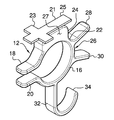
- FIG. 1 is a front perspective view of a clamping support assembly according to an embodiment of the disclosure.
- FIG. 2 is a left side view of an embodiment of the disclosure.
- FIG. 3 is a front view of an embodiment of the disclosure.
- FIG. 4 is a right side view of an embodiment of the disclosure.
- FIG. 5 is a perspective in-use view of an embodiment of the disclosure.
- FIGS. 1 through 5 a new clamping device embodying the principles and concepts of an embodiment of the disclosure and generally designated by the reference numeral 10 will be described.
- the clamping support assembly 10 generally comprises a clamp 12 that is selectively manipulated.
- the clamp 12 is biased into a closed position to engage a platform 14 .
- the platform 14 may be a table top, a counter top and any other horizontally planar platform 14 .
- the clamp 12 has a central portion 16 extending between a top finger 18 and a bottom finger 20 .
- the central portion 16 is arcuate between each of the top 18 and bottom 20 portions such that the central portion 16 forms an open loop.
- the top finger 18 is spaced from the bottom finger 20 and the top finger 18 is biased toward the bottom finger 20 .
- each of the top 18 and bottom 20 fingers may frictionally engage an associated one of a top surface and a bottom surface of the platform 14 .
- the central portion 16 has an outwardly facing surface 22 and a prominence 24 extends upwardly from the outwardly facing surface 22 .
- the prominence 24 is centrally positioned between the top finger 18 and a midpoint 26 of the central portion 16 .
- the prominence 24 has a lateral surface 27 and indicia may be printed on the lateral surface 27 .
- the indicia may comprise letters and the letters may spell “love u” or the like.
- a cross 21 may be provided and the cross may be coupled to the prominence 24 .
- the cross 21 may be displayed when the clamp 12 is manipulated to engage the platform 14 .
- the cross 21 may have a first member 23 that intersects a second member 25 at a right angle.
- the first member 23 may have a length that is less than a length of the second member 25 .
- the cross 21 may resemble the Christian cross.
- a first tab 28 extends away from the outwardly facing surface 22 and the first tab 28 is selectively manipulated.
- the first tab 28 is positioned between the prominence 24 and the midpoint 26 .
- a second tab 30 extends away from the outwardly facing surface 22 and the second tab 30 is selectively manipulated.
- the second tab 30 is positioned on an opposite side of the midpoint 26 with respect to the first tab 28 .
- Each of the first tab 28 and the second tab 30 is selectively urged toward each other. In this way the top finger 18 is urged away from the bottom finger 20 thereby facilitating the platform 14 to be positioned between the top 18 and bottom 20 fingers.
- the central portion 16 may be comprised of a resiliently bendable material.
- a hook 32 is coupled to the clamp 12 and an object 33 may be suspended from the hook 32 .
- the object 33 may be suspended from the platform 14 .
- the object may be strap on a purse or the like.
- the hook 32 extends outwardly from the outwardly facing surface 22 of the central portion 16 .
- the hook 32 is centrally positioned between the second tab 30 and the bottom finger 20 .
- the hook 32 has a distal end 34 with respect to the outwardly facing surface 22 .
- the hook 32 is curved between the outwardly facing surface 22 and the distal end 34 .
- each of the first 28 and second 30 tabs are urged toward each other thereby facilitating the top finger 18 of the clamp 12 to be urged away from the bottom finger 20 of the clamp 12 .
- the clamp 12 is manipulated to position the platform 14 between the top 18 and bottom 20 portions.
- Each of the first 28 and second 30 tabs is released.
- the object 33 is selectively suspended from the hook 32 for storage.
Landscapes
- Engineering & Computer Science (AREA)
- General Engineering & Computer Science (AREA)
- Mechanical Engineering (AREA)
- Clamps And Clips (AREA)
Abstract
A clamping support assembly for suspending an object from a platform includes a clamp that is selectively manipulated. The clamp is biased into a closed position to engage a platform. A hook is coupled to the clamp. An object is selectively suspended from the clamp thereby facilitating the object to be suspended from the platform.
Description
Not Applicable
Not Applicable
Not Applicable
Not Applicable
Not Applicable
The disclosure and prior art relates to clamping devices and more particularly pertains to a new clamping device for suspending an object from a platform.
An embodiment of the disclosure meets the needs presented above by generally comprising a clamp that is selectively manipulated. The clamp is biased into a closed position to engage a platform. A hook is coupled to the clamp. An object is selectively suspended from the clamp thereby facilitating the object to be suspended from the platform.
There has thus been outlined, rather broadly, the more important features of the disclosure in order that the detailed description thereof that follows may be better understood, and in order that the present contribution to the art may be better appreciated. There are additional features of the disclosure that will be described hereinafter and which will form the subject matter of the claims appended hereto.
The objects of the disclosure, along with the various features of novelty which characterize the disclosure, are pointed out with particularity in the claims annexed to and forming a part of this disclosure.
The disclosure will be better understood and objects other than those set forth above will become apparent when consideration is given to the following detailed description thereof. Such description makes reference to the annexed drawings wherein:
With reference now to the drawings, and in particular to FIGS. 1 through 5 thereof, a new clamping device embodying the principles and concepts of an embodiment of the disclosure and generally designated by the reference numeral 10 will be described.
As best illustrated in FIGS. 1 through 5 , the clamping support assembly 10 generally comprises a clamp 12 that is selectively manipulated. The clamp 12 is biased into a closed position to engage a platform 14. The platform 14 may be a table top, a counter top and any other horizontally planar platform 14. The clamp 12 has a central portion 16 extending between a top finger 18 and a bottom finger 20. The central portion 16 is arcuate between each of the top 18 and bottom 20 portions such that the central portion 16 forms an open loop.
The top finger 18 is spaced from the bottom finger 20 and the top finger 18 is biased toward the bottom finger 20. Thus, each of the top 18 and bottom 20 fingers may frictionally engage an associated one of a top surface and a bottom surface of the platform 14. The central portion 16 has an outwardly facing surface 22 and a prominence 24 extends upwardly from the outwardly facing surface 22. Moreover, the prominence 24 is centrally positioned between the top finger 18 and a midpoint 26 of the central portion 16. The prominence 24 has a lateral surface 27 and indicia may be printed on the lateral surface 27. The indicia may comprise letters and the letters may spell “love u” or the like.
A cross 21 may be provided and the cross may be coupled to the prominence 24. Thus, the cross 21 may be displayed when the clamp 12 is manipulated to engage the platform 14. The cross 21 may have a first member 23 that intersects a second member 25 at a right angle. The first member 23 may have a length that is less than a length of the second member 25. Thus, the cross 21 may resemble the Christian cross.
A first tab 28 extends away from the outwardly facing surface 22 and the first tab 28 is selectively manipulated. The first tab 28 is positioned between the prominence 24 and the midpoint 26. A second tab 30 extends away from the outwardly facing surface 22 and the second tab 30 is selectively manipulated. The second tab 30 is positioned on an opposite side of the midpoint 26 with respect to the first tab 28. Each of the first tab 28 and the second tab 30 is selectively urged toward each other. In this way the top finger 18 is urged away from the bottom finger 20 thereby facilitating the platform 14 to be positioned between the top 18 and bottom 20 fingers. The central portion 16 may be comprised of a resiliently bendable material.
A hook 32 is coupled to the clamp 12 and an object 33 may be suspended from the hook 32. In this way the object 33 may be suspended from the platform 14. The object may be strap on a purse or the like. The hook 32 extends outwardly from the outwardly facing surface 22 of the central portion 16. Moreover, the hook 32 is centrally positioned between the second tab 30 and the bottom finger 20. The hook 32 has a distal end 34 with respect to the outwardly facing surface 22. The hook 32 is curved between the outwardly facing surface 22 and the distal end 34.
In use, each of the first 28 and second 30 tabs are urged toward each other thereby facilitating the top finger 18 of the clamp 12 to be urged away from the bottom finger 20 of the clamp 12. The clamp 12 is manipulated to position the platform 14 between the top 18 and bottom 20 portions. Each of the first 28 and second 30 tabs is released. Thus, the top 18 and bottom 20 fingers frictionally engage the platform 14. The object 33 is selectively suspended from the hook 32 for storage.
With respect to the above description then, it is to be realized that the optimum dimensional relationships for the parts of an embodiment enabled by the disclosure, to include variations in size, materials, shape, form, function and manner of operation, assembly and use, are deemed readily apparent and obvious to one skilled in the art, and all equivalent relationships to those illustrated in the drawings and described in the specification are intended to be encompassed by an embodiment of the disclosure.
Therefore, the foregoing is considered as illustrative only of the principles of the disclosure. Further, since numerous modifications and changes will readily occur to those skilled in the art, it is not desired to limit the disclosure to the exact construction and operation shown and described, and accordingly, all suitable modifications and equivalents may be resorted to, falling within the scope of the disclosure. In this patent document, the word “comprising” is used in its non-limiting sense to mean that items following the word are included, but items not specifically mentioned are not excluded. A reference to an element by the indefinite article “a” does not exclude the possibility that more than one of the element is present, unless the context clearly requires that there be only one of the elements.
Claims (6)
1. A clamping support assembly being configured to engage a support thereby facilitating a purse to be suspended from the support, said assembly comprising:
a clamp being configured to be manipulated, said clamp being biased into a closed position wherein said clamp is configured to engage a platform, said clamp having a central portion extending between a top finger and a bottom finger, said central portion being arcuate between each of said top and bottom fingers such that said central portion forms an open loop having said top finger being spaced from said bottom finger, said central portion having an outwardly facing surface, said central portion having a prominence extending upwardly from said outwardly facing surface, said prominence being centrally positioned between said top finger and a midpoint of said central portion;
a first tab extending away from said outwardly facing surface wherein said first tab is configured to be manipulated, said first tab being positioned between said prominence and said midpoint; and
a hook being coupled to said clamp wherein said hook is configured to have an object suspended therefrom thereby facilitating the object to be suspended from the platform.
2. The assembly according to claim 1 , wherein said top finger is biased toward said bottom finger wherein each of said top and bottom fingers are configured to frictionally engage an associated one of a top surface and a bottom surface of the platform.
3. The assembly according to claim 1 , further comprising a second tab extending away from said outwardly facing surface wherein said second tab is configured to be manipulated, said second tab being positioned on an opposite side of said midpoint with respect to said first tab.
4. The assembly according to claim 3 , wherein each of said first tab and said second tab is selectively urged toward each other such that said top finger is urged away from said bottom finger wherein each of said top and bottom fingers is configured to have the platform positioned between said top and bottom fingers.
5. The assembly according to claim 3 , wherein said hook extends outwardly from said outwardly facing surface of said central portion, said hook being centrally positioned between said second tab and said bottom finger, said hook having a distal end with respect to said outwardly facing surface, said hook being curved between said outwardly facing surface and said distal end.
6. A clamping support assembly being configured to engage a support thereby facilitating a purse to be suspended from the support, said assembly comprising:
a clamp being configured to be manipulated, said clamp being biased into a closed position wherein said clamp is configured to engage a platform, said clamp having a central portion extending between a top finger and a bottom finger, said central portion being arcuate between each of said top and bottom fingers such that said central portion forms an open loop having said top finger being spaced from said bottom finger, said top finger being biased toward said bottom finger wherein each of said top and bottom fingers are configured to frictionally engage an associated one of a top surface and a bottom surface of the platform, said central portion having an outwardly facing surface, said central portion having a prominence extending upwardly from said outwardly facing surface, said prominence being centrally positioned between said top finger and an midpoint of said central portion;
a first tab extending away from said outwardly facing surface wherein said first tab is configured to be manipulated, said first tab being positioned between said prominence and said midpoint;
a second tab extending away from said outwardly facing surface wherein said second tab is configured to be manipulated, said second tab being positioned on an opposite side of said midpoint with respect to said first tab, each of said first tab and said second tab being selectively urged toward each other such that said top finger is urged away from said bottom finger wherein each of said top and bottom fingers is configured to have the platform positioned between said top and bottom fingers; and
a hook being coupled to said clamp wherein said hook is configured to have an object suspended therefrom thereby facilitating the object to be suspended from the platform, said hook extending outwardly from said outwardly facing surface of said central portion, said hook being centrally positioned between said second tab and said bottom finger, said hook having a distal end with respect to said outwardly facing surface, said hook being curved between said outwardly facing surface and said distal end.
Priority Applications (1)
| Application Number | Priority Date | Filing Date | Title |
|---|---|---|---|
| US15/660,580 US10022006B1 (en) | 2017-07-26 | 2017-07-26 | Clamping support assembly |
Applications Claiming Priority (1)
| Application Number | Priority Date | Filing Date | Title |
|---|---|---|---|
| US15/660,580 US10022006B1 (en) | 2017-07-26 | 2017-07-26 | Clamping support assembly |
Publications (1)
| Publication Number | Publication Date |
|---|---|
| US10022006B1 true US10022006B1 (en) | 2018-07-17 |
Family
ID=62837428
Family Applications (1)
| Application Number | Title | Priority Date | Filing Date |
|---|---|---|---|
| US15/660,580 Active US10022006B1 (en) | 2017-07-26 | 2017-07-26 | Clamping support assembly |
Country Status (1)
| Country | Link |
|---|---|
| US (1) | US10022006B1 (en) |
Cited By (6)
| Publication number | Priority date | Publication date | Assignee | Title |
|---|---|---|---|---|
| WO2020181179A1 (en) * | 2019-03-07 | 2020-09-10 | Thornton Brandon | Hanging device |
| US20220099304A1 (en) * | 2020-09-28 | 2022-03-31 | Shauna Jessop | Oven handle fastener |
| US20220263301A1 (en) * | 2021-02-18 | 2022-08-18 | Dino Group Pty Ltd | Cable Management Devices |
| US11419443B2 (en) | 2020-11-02 | 2022-08-23 | MillerKnoll, Inc. | Accessory hook |
| JP7390714B2 (en) | 2020-02-06 | 2023-12-04 | セイキ工業株式会社 | article holder |
| US20240245247A1 (en) * | 2023-01-21 | 2024-07-25 | Brittany Scott | Hook for Suspending a Purse |
Citations (30)
| Publication number | Priority date | Publication date | Assignee | Title |
|---|---|---|---|---|
| US1220717A (en) * | 1916-05-16 | 1917-03-27 | William C Bennett | Detachable hook. |
| US2124483A (en) | 1936-10-12 | 1938-07-19 | S K Rowe | Lady's handbag holder |
| US2461071A (en) * | 1946-09-25 | 1949-02-08 | Michael W Mettenleiter | Handbag holder or the like |
| US2516760A (en) | 1950-04-28 | 1950-07-25 | James A Doran | Device for holding gloves and suspending a handbag from a support |
| US2555890A (en) * | 1949-06-29 | 1951-06-05 | Hazel M Korth | Bracelet and utility holder |
| US2565719A (en) * | 1949-06-22 | 1951-08-28 | Franklin O Church | Support for handbags and other articles |
| US2875970A (en) * | 1956-06-14 | 1959-03-03 | John C Gardner | Bag holder |
| US3300168A (en) * | 1965-09-15 | 1967-01-24 | Orlando A Gaudino | Visor clip |
| US3376006A (en) * | 1966-09-19 | 1968-04-02 | Zezula Mary | Suspension clamp device |
| US3767152A (en) * | 1972-06-28 | 1973-10-23 | W Killinger | Tabletop clamp |
| US3799416A (en) * | 1971-05-10 | 1974-03-26 | L Schmaltz | Hand grip clothes carrier |
| US4118001A (en) * | 1978-04-10 | 1978-10-03 | Serkez Alvin A | Handbag holder |
| US4210302A (en) * | 1979-04-06 | 1980-07-01 | Serkez Alvin A | Handbag holder |
| US4728069A (en) | 1986-12-16 | 1988-03-01 | Semcer John P | Article attachment for bars, tables and the like |
| USD314864S (en) | 1988-09-28 | 1991-02-26 | Creed Kenny D | Table top hook for purse or similar article |
| US5314151A (en) * | 1992-12-11 | 1994-05-24 | Carter Mann Candice | Plastic bag hanger device |
| US5797567A (en) * | 1996-05-23 | 1998-08-25 | Magnafici; Bill | Easy fill locking bag holder |
| US6345796B1 (en) * | 2000-12-19 | 2002-02-12 | P.K. Torten Enterprises | Table hook for purses and the like |
| US6390431B1 (en) * | 2000-08-17 | 2002-05-21 | Gail F. Ott | Beverage cup holder for attachment to a wheeled suitcase |
| US20050056746A1 (en) * | 2003-09-12 | 2005-03-17 | Michael Landver | Baggage holder |
| US7644900B2 (en) | 2006-08-15 | 2010-01-12 | Luxe Link, Llc | Portable hanger for purse |
| US7828258B2 (en) * | 2008-08-04 | 2010-11-09 | Shigio Linda T | Personal accessory hanger |
| US20120198680A1 (en) * | 2011-02-08 | 2012-08-09 | Durben David P | Flexible Securing Device |
| US8308125B2 (en) * | 2009-09-14 | 2012-11-13 | Monte Roger Losaw | Selectively adjustable device for securing a handbag |
| US20130056602A1 (en) * | 2011-09-06 | 2013-03-07 | Srbijanka Zivku | Flexible Bag Holder |
| US8668177B2 (en) * | 2012-08-09 | 2014-03-11 | The Finding Ip Holding Company Llc | Combination purse hanger and object retainer |
| US20140284360A1 (en) * | 2013-03-25 | 2014-09-25 | Steven D. Chorazewitz | Bottle docking device |
| US9080715B2 (en) * | 2013-10-02 | 2015-07-14 | Steelcase Inc. | Support device for suspending an article from a horizontal object |
| US20160355205A1 (en) * | 2015-07-20 | 2016-12-08 | Cheryl Glynn Upton | Device Holding Clip for Shopping Cart |
| US9631771B1 (en) * | 2015-11-17 | 2017-04-25 | Four Strong Corporation | Manually actuatable hanger for suspending articles from a tubular carrier structure |
-
2017
- 2017-07-26 US US15/660,580 patent/US10022006B1/en active Active
Patent Citations (30)
| Publication number | Priority date | Publication date | Assignee | Title |
|---|---|---|---|---|
| US1220717A (en) * | 1916-05-16 | 1917-03-27 | William C Bennett | Detachable hook. |
| US2124483A (en) | 1936-10-12 | 1938-07-19 | S K Rowe | Lady's handbag holder |
| US2461071A (en) * | 1946-09-25 | 1949-02-08 | Michael W Mettenleiter | Handbag holder or the like |
| US2565719A (en) * | 1949-06-22 | 1951-08-28 | Franklin O Church | Support for handbags and other articles |
| US2555890A (en) * | 1949-06-29 | 1951-06-05 | Hazel M Korth | Bracelet and utility holder |
| US2516760A (en) | 1950-04-28 | 1950-07-25 | James A Doran | Device for holding gloves and suspending a handbag from a support |
| US2875970A (en) * | 1956-06-14 | 1959-03-03 | John C Gardner | Bag holder |
| US3300168A (en) * | 1965-09-15 | 1967-01-24 | Orlando A Gaudino | Visor clip |
| US3376006A (en) * | 1966-09-19 | 1968-04-02 | Zezula Mary | Suspension clamp device |
| US3799416A (en) * | 1971-05-10 | 1974-03-26 | L Schmaltz | Hand grip clothes carrier |
| US3767152A (en) * | 1972-06-28 | 1973-10-23 | W Killinger | Tabletop clamp |
| US4118001A (en) * | 1978-04-10 | 1978-10-03 | Serkez Alvin A | Handbag holder |
| US4210302A (en) * | 1979-04-06 | 1980-07-01 | Serkez Alvin A | Handbag holder |
| US4728069A (en) | 1986-12-16 | 1988-03-01 | Semcer John P | Article attachment for bars, tables and the like |
| USD314864S (en) | 1988-09-28 | 1991-02-26 | Creed Kenny D | Table top hook for purse or similar article |
| US5314151A (en) * | 1992-12-11 | 1994-05-24 | Carter Mann Candice | Plastic bag hanger device |
| US5797567A (en) * | 1996-05-23 | 1998-08-25 | Magnafici; Bill | Easy fill locking bag holder |
| US6390431B1 (en) * | 2000-08-17 | 2002-05-21 | Gail F. Ott | Beverage cup holder for attachment to a wheeled suitcase |
| US6345796B1 (en) * | 2000-12-19 | 2002-02-12 | P.K. Torten Enterprises | Table hook for purses and the like |
| US20050056746A1 (en) * | 2003-09-12 | 2005-03-17 | Michael Landver | Baggage holder |
| US7644900B2 (en) | 2006-08-15 | 2010-01-12 | Luxe Link, Llc | Portable hanger for purse |
| US7828258B2 (en) * | 2008-08-04 | 2010-11-09 | Shigio Linda T | Personal accessory hanger |
| US8308125B2 (en) * | 2009-09-14 | 2012-11-13 | Monte Roger Losaw | Selectively adjustable device for securing a handbag |
| US20120198680A1 (en) * | 2011-02-08 | 2012-08-09 | Durben David P | Flexible Securing Device |
| US20130056602A1 (en) * | 2011-09-06 | 2013-03-07 | Srbijanka Zivku | Flexible Bag Holder |
| US8668177B2 (en) * | 2012-08-09 | 2014-03-11 | The Finding Ip Holding Company Llc | Combination purse hanger and object retainer |
| US20140284360A1 (en) * | 2013-03-25 | 2014-09-25 | Steven D. Chorazewitz | Bottle docking device |
| US9080715B2 (en) * | 2013-10-02 | 2015-07-14 | Steelcase Inc. | Support device for suspending an article from a horizontal object |
| US20160355205A1 (en) * | 2015-07-20 | 2016-12-08 | Cheryl Glynn Upton | Device Holding Clip for Shopping Cart |
| US9631771B1 (en) * | 2015-11-17 | 2017-04-25 | Four Strong Corporation | Manually actuatable hanger for suspending articles from a tubular carrier structure |
Cited By (8)
| Publication number | Priority date | Publication date | Assignee | Title |
|---|---|---|---|---|
| WO2020181179A1 (en) * | 2019-03-07 | 2020-09-10 | Thornton Brandon | Hanging device |
| JP7390714B2 (en) | 2020-02-06 | 2023-12-04 | セイキ工業株式会社 | article holder |
| US20220099304A1 (en) * | 2020-09-28 | 2022-03-31 | Shauna Jessop | Oven handle fastener |
| US11988389B2 (en) * | 2020-09-28 | 2024-05-21 | Shauna Jessop | Oven handle fastener |
| US11419443B2 (en) | 2020-11-02 | 2022-08-23 | MillerKnoll, Inc. | Accessory hook |
| US20220263301A1 (en) * | 2021-02-18 | 2022-08-18 | Dino Group Pty Ltd | Cable Management Devices |
| US12027838B2 (en) * | 2021-02-18 | 2024-07-02 | Dino Group Pty Ltd | Cable management devices |
| US20240245247A1 (en) * | 2023-01-21 | 2024-07-25 | Brittany Scott | Hook for Suspending a Purse |
Similar Documents
| Publication | Publication Date | Title |
|---|---|---|
| US10022006B1 (en) | Clamping support assembly | |
| US10117505B1 (en) | Electronic case assembly | |
| US10383379B2 (en) | Electronic device holding system | |
| US20190191910A1 (en) | Clothes Hanger Organization Assembly | |
| US9901796B2 (en) | Smart phone holding system | |
| US9392865B2 (en) | Electronic device theft prevention assembly | |
| US10660426B2 (en) | Electronic device harness assembly | |
| US9833082B1 (en) | Pillow dressing system | |
| US11084317B1 (en) | Writing utensil assembly | |
| US20180159579A1 (en) | Smartphone Case Assembly | |
| US20190208833A1 (en) | Handkerchief securing assembly | |
| US20200237130A1 (en) | Adjustable clothes hanger assembly | |
| US10368703B2 (en) | Toilet paper holding system | |
| US20190191824A1 (en) | Nonmetallic Belt Buckle Assembly | |
| US10039393B1 (en) | Calendar frame assembly | |
| US10099626B1 (en) | Garment hanging device | |
| US9902325B1 (en) | Portable climbing system | |
| US20190363747A1 (en) | Smart phone case assembly | |
| US20210107736A1 (en) | Garbage Can Retaining Clip Apparatus | |
| US20200147994A1 (en) | Hanging folder assembly | |
| US11219299B1 (en) | Electronic tablet holder assembly | |
| US20190174965A1 (en) | Friction Reducing Pad System | |
| US10796612B1 (en) | Vanity plate assembly | |
| US20190021421A1 (en) | Apparel Protecting Device | |
| US10765120B2 (en) | Hinged panel assembly |
Legal Events
| Date | Code | Title | Description |
|---|---|---|---|
| STCF | Information on status: patent grant |
Free format text: PATENTED CASE |
|
| MAFP | Maintenance fee payment |
Free format text: PAYMENT OF MAINTENANCE FEE, 4TH YEAR, MICRO ENTITY (ORIGINAL EVENT CODE: M3551); ENTITY STATUS OF PATENT OWNER: MICROENTITY Year of fee payment: 4 |
|
| MAFP | Maintenance fee payment |
Free format text: PAYMENT OF MAINTENANCE FEE, 8TH YEAR, MICRO ENTITY (ORIGINAL EVENT CODE: M3552); ENTITY STATUS OF PATENT OWNER: MICROENTITY Year of fee payment: 8 |