US10017092B1 - Adjustable truckbed with extendable ramp - Google Patents
Adjustable truckbed with extendable ramp Download PDFInfo
- Publication number
- US10017092B1 US10017092B1 US15/687,515 US201715687515A US10017092B1 US 10017092 B1 US10017092 B1 US 10017092B1 US 201715687515 A US201715687515 A US 201715687515A US 10017092 B1 US10017092 B1 US 10017092B1
- Authority
- US
- United States
- Prior art keywords
- ramp
- bridge
- bedrunner
- loading
- truck
- Prior art date
- Legal status (The legal status is an assumption and is not a legal conclusion. Google has not performed a legal analysis and makes no representation as to the accuracy of the status listed.)
- Expired - Fee Related
Links
- 238000011068 loading method Methods 0.000 claims abstract description 65
- 239000000463 material Substances 0.000 claims abstract description 5
- 230000007246 mechanism Effects 0.000 claims description 13
- 230000014759 maintenance of location Effects 0.000 claims 3
- 239000000126 substance Substances 0.000 claims 3
- 238000010276 construction Methods 0.000 abstract description 2
- 230000009471 action Effects 0.000 description 3
- 238000000605 extraction Methods 0.000 description 2
- 238000000034 method Methods 0.000 description 2
- 239000003381 stabilizer Substances 0.000 description 2
- 238000006467 substitution reaction Methods 0.000 description 2
- 241000083700 Ambystoma tigrinum virus Species 0.000 description 1
- 239000004606 Fillers/Extenders Substances 0.000 description 1
- 244000261422 Lysimachia clethroides Species 0.000 description 1
- 244000046052 Phaseolus vulgaris Species 0.000 description 1
- 235000010627 Phaseolus vulgaris Nutrition 0.000 description 1
- 239000011248 coating agent Substances 0.000 description 1
- 238000000576 coating method Methods 0.000 description 1
- 230000008878 coupling Effects 0.000 description 1
- 238000010168 coupling process Methods 0.000 description 1
- 238000005859 coupling reaction Methods 0.000 description 1
- 230000007423 decrease Effects 0.000 description 1
- 230000003247 decreasing effect Effects 0.000 description 1
- 238000006073 displacement reaction Methods 0.000 description 1
- 238000001125 extrusion Methods 0.000 description 1
- 239000002184 metal Substances 0.000 description 1
- 230000004048 modification Effects 0.000 description 1
- 238000012986 modification Methods 0.000 description 1
- 238000002360 preparation method Methods 0.000 description 1
- 238000000926 separation method Methods 0.000 description 1
- 239000004753 textile Substances 0.000 description 1
Images


Classifications
-
- B—PERFORMING OPERATIONS; TRANSPORTING
- B60—VEHICLES IN GENERAL
- B60P—VEHICLES ADAPTED FOR LOAD TRANSPORTATION OR TO TRANSPORT, TO CARRY, OR TO COMPRISE SPECIAL LOADS OR OBJECTS
- B60P1/00—Vehicles predominantly for transporting loads and modified to facilitate loading, consolidating the load, or unloading
- B60P1/43—Vehicles predominantly for transporting loads and modified to facilitate loading, consolidating the load, or unloading using a loading ramp mounted on the vehicle
- B60P1/431—Vehicles predominantly for transporting loads and modified to facilitate loading, consolidating the load, or unloading using a loading ramp mounted on the vehicle the ramp being stored under the loading floor when not in use
-
- B—PERFORMING OPERATIONS; TRANSPORTING
- B60—VEHICLES IN GENERAL
- B60P—VEHICLES ADAPTED FOR LOAD TRANSPORTATION OR TO TRANSPORT, TO CARRY, OR TO COMPRISE SPECIAL LOADS OR OBJECTS
- B60P1/00—Vehicles predominantly for transporting loads and modified to facilitate loading, consolidating the load, or unloading
- B60P1/43—Vehicles predominantly for transporting loads and modified to facilitate loading, consolidating the load, or unloading using a loading ramp mounted on the vehicle
- B60P1/433—Vehicles predominantly for transporting loads and modified to facilitate loading, consolidating the load, or unloading using a loading ramp mounted on the vehicle the loading floor or a part thereof being movable to form the ramp
-
- B—PERFORMING OPERATIONS; TRANSPORTING
- B60—VEHICLES IN GENERAL
- B60P—VEHICLES ADAPTED FOR LOAD TRANSPORTATION OR TO TRANSPORT, TO CARRY, OR TO COMPRISE SPECIAL LOADS OR OBJECTS
- B60P1/00—Vehicles predominantly for transporting loads and modified to facilitate loading, consolidating the load, or unloading
- B60P1/43—Vehicles predominantly for transporting loads and modified to facilitate loading, consolidating the load, or unloading using a loading ramp mounted on the vehicle
- B60P1/435—Vehicles predominantly for transporting loads and modified to facilitate loading, consolidating the load, or unloading using a loading ramp mounted on the vehicle the ramp being attached to or making part of the side- or tailboards of the vehicle
-
- B—PERFORMING OPERATIONS; TRANSPORTING
- B62—LAND VEHICLES FOR TRAVELLING OTHERWISE THAN ON RAILS
- B62D—MOTOR VEHICLES; TRAILERS
- B62D33/00—Superstructures for load-carrying vehicles
- B62D33/02—Platforms; Open load compartments
- B62D33/023—Sideboard or tailgate structures
- B62D33/027—Sideboard or tailgate structures movable
- B62D33/0273—Movable tailboards for vehicles comprising non-movable sideboards, e.g. pick-up trucks
Definitions
- the inventive concept presented herein is generally concerned with devices and methods for operating an efficient, extendable loading ramp with sufficient strength and durability to on-load and off load objects, particularly wheeled equipment and vehicles.
- Ramps have been designed to be carried within the cargo area of a truck and deployed at the time of loading or unloading cargo. Most of these ramps take up valuable cargo space and usually must be secured with heavy-duty straps or other restraints. This may take considerable time to store and/or deploy such ramps. It is not compact nor is it convenient and easy to extend or assemble quickly.
- Some solutions utilize a tailgate with a ramp that is troublesome, overly-large, or difficult to install and operate and usually requires removal of the factory-equipped tailgate.
- the inventive concept herein provides a safe, inexpensive, strong, simple to operate, extendable ramp system that can be securely installed in a compact space occupying no more than four inches vertically above the truck's bed.
- U.S. Pat. No. 9,073,475 (Jul. 7, 2015) (Chastain, R.) Disclosed is an adjustable-length, variable-tracked ramp loading system attachable to a stationary loading dock or to the bed of any of a variety of trucks, said ramp loading system functioning to assist with the loading of assorted types of cargo including mowing equipment, wheeled vehicles, construction equipment, supplies, materials, and other objects of dimensions compatible with the size of the ramps which comprise the ramp loading system installed.
- the system is constructed and operates with a minimum of two (2) extendable ramps, each ramp reinforced with four lengthwise I-beams. Each ramp is manually pulled out from its individual bridge, which bridge itself is stored inside horizontally-oriented primarily longitudinal housing channels attached to the bed of the thick or loading dock.
- the ramps may be extended and angularly lowered at varying distances from the rear of the truck bed or dock.
- a configurable pickup bed utility management system features a segmented panel assembly pivotally mounted to a pickup bed.
- the panel assembly features a first panel, a second panel pivotally located on the first panel, a third panel pivotally located on the second panel, and a fourth panel pivotally located on the third panel.
- a plurality of curved linear extrusions with ridges are located on the panels.
- the panel assembly can be fully extended over the pickup bed forming a bed cover structure, fully extended posterior to the pickup bed forming a work surface structure, fully extended posterior to the pickup bed forming a ramp structure, partially extended posterior to the pickup bed forming a sun shade structure, folded into the pickup bed forming a lockable toolbox, or folded into the pickup bed forming a bed extender.
- the tailgate storage case assembly is made of an elongated hollow storage compartment having a closed front end and an open rear end.
- a pivot bracket is mounted to the storage compartment near the front end for supporting the front end to the sidewall of a pickup truck box.
- the pivot bracket has a pivot joint therein for allowing an angular displacement of the hollow storage compartment about the pivot joint.
- the storage case assembly also includes a latch bracket mounted to the storage compartment near the rear end thereof for supporting the rear end to the sidewall.
- the latch bracket has a slide surface thereon for allowing the rear end of the hollow storage compartment to be displaced toward and away from the sidewall to define a clearance between a ramp being stowed in the storage case assembly and the tailgate post of the pickup truck.
- US 2011/0072596 Disclosed is a system extending a ramp from a storage position on a vehicle tailgate or flatbed.
- the device has a collection box channel with a sliding member slidingly engaged and moving within the collection box channel and coupling an end of the ramp to the collection box, the sliding member being coupled to the end of ramp closest to the collection box when the ramp is extended.
- Two support hinge members couple the two folding support members, where the two folding support members extend, unfold, and pivot on the two support hinge members and straighten and the extension member extends on the control element to extend the ramp.
- U.S. Pat. No. 7,976,264 B1 Jul. 12, 2011; Pope, T.
- a truck bed platform apparatus is provided as replacement or original equipment.
- An access below the platform selectively houses the individually rollingly removable ramps.
- Bi-directional hinges which fasten each ramp second section to each first section are lockable, giving the ramps infinite incline and decline capabilities.
- Bi-directional lockable hinges affix each third section to each second section for the same reason. Varied lengths of the hinged legs also provide selective angle and support for each ramp.
- the invention is a device that may be mounted on a bed of a pickup truck for smaller vehicles, such as motorcycles, snowmobiles, or all-terrain vehicles to enter from the ground upon a platform of the loading device.
- the loading device has a ramp that can be pulled outwardly or rearwardly form said device, and a motorcycle can drive up the ramp to the platform.
- a dolly slide is polled outwardly from the device, and extends above the tailgate. The ramp then extends downwardly from the dolly slide, so that no weight or load is displaced on the tailgate.
- U.S. Pat. No. 7,810,196 B1 (Oct. 12, 2010; Pritchard et al.)
- the invention as presently conceived discloses a variable length system attachable to a standard pickup truck that assists with the loading of all-terrain vehicles and similar items.
- the length of each ramp can vary independently with the other from four feet to a maximum of eight feet.
- the extension is similar to that of an extension ladder in which one piece slides inside the other.
- a textile strap with connectors provides further securement of the ramps with the truck body. When not in use, the ramps can be collapsed and stored in minimal space.
- a compact ramp and tailgate system for a vehicle tailgate includes a tailgate having an interior hollow cavity for collapsible storage therein of a pair of ramps that are also telescopically extendable therefrom for loading and unloading equipment into and off the bed of the vehicle such as a pickup truck.
- each ramp is mounted to a locking hinge that allows the ramps to pivot up to ninety degrees and each ramp composed of at least three ramp members of decreasing size starting from the largest ramp members that are pivotally interconnected to the locking hinges.
- U.S. Pat. No. 7,524,156 B2 (Apr. 28, 2009; Garbes, L.) Disclosed is a portable ramp and tool container for use in the bed of a pickup truck where the container includes interchangeable retractable and extendable ramps and tool trays which pull out from the container. Portions of the ramps can pivot downward to contact the ground while the tool tray may have a leg attached for support.
- the invention is a three-section foldable loading ramp extending a pick-up truck's cargo area to accommodate heavy and lengthy items.
- the first, or frame section of the loading ramp installs onto the existing tailgate slip hinges in place of the tailgate without tools or modification of the vehicle.
- Upper and lower ramp sections are pivotally connected to each other and to the frame section in a similar manner.
- An arm carried by the first frame section pivots down onto the vehicle's hitch for additional support for the ramp.
- Two legs pivot down from the upper ramp to the ground, providing further support.
- U.S. Pat. No. 7,309,202 B1 (Dec. 18, 2007: Anderson, M.) A system for transporting and storing a portable combination table/ramp device in a truck, including a substantially flat platform supported by a plurality of support members positioned between the platform and the truck bed and defining a plurality of elongated recesses there between. Elongated table top portion and elongated bench seat portions with tailgate-engaging portions connected thereto are received in the recesses.
- a ramp assembly for use in a vehicle provides access thereto by users having restricted mobility.
- the ramp assembly comprises a ramp platform displaceable relative to a mounting structure between a retracted position and a deployed position.
- a drive mechanism is disposed within the mounting structure and operates to displace the ramp platform between the retracted and the deployed positions.
- US 2004/0009055 A1 Shows a tilting ramp is for mounting to a truck, and once so mounted, for loading, unloading and transport of at least one personal recreational vehicle.
- the ramp is slidable over the bed of the truck.
- a pivot member is mounted into a receiver tube mounted to the truck.
- the pivot member extends upwardly into translational engagement with the ramp.
- the ramp may be translated over both the bed and the pivot member between a transport position forward on the bed and a pivoting position pivotable about the pivot member. In the pivoting position the ramp is pivotable between the horizontal and an inclined position contacting the ground.
- U.S. Pat. No. 6,705,820 B2 (Mar. 16, 2004) (Schilling, H.) A carrier/lift adapted to be mounted in a truck bed, and having a carrying platform that pivots and translates in a constrained manner along a pair of tracks to an inclined loading position for safe and convenient loading of the vehicle into the bed of a truck.
- a platform having a recess for storage of a pair of nestable loading ramps is also disclosed. The platform can be supported above the floor of a truck bed to provide usable storage space in the bed of the truck between the platform (with the nested ramps stowed therein) and the floor of the truck bed.
- US 2004/0223836 A1 (Nov. 11, 2004; Robertson, R.) A vehicle ramp assembly for loading ATVs and like things onto transporting vehicles.
- the ramp assembly includes a pair of ramps positioned side-by-side. Each of the ramps has an upper end for engagement with a transporting vehicle and a lower end for positioning upon the ground.
- At least one crosspiece connects the ramps together between the upper and lower ends thereof. The crosspiece is releasably fastened to one of the ramps and is pivotally fastened to the other one of the ramps for compact storage.
- a pickup truck tailgate and loading ramp is formed by a main frame dimensioned to be hingedly received by a given pickup bed.
- Two pairs of hingedly interconnected frames are rigidly secured to the top rail of the tailgate section and form a pair of ramp tracks when in tailgate lowered position. When not in use the track forming frames are disposed rearwardly of the closed tailgate section.
- This invention is a tailgate comprising a plurality of foldable members configured to nest one with the others in an upright closed position and to extend longitudinally from the rear of the truck when in an extended position.
- a notched section is positioned at a top side of the plurality of foldable members when in an upright position for accommodating a goose neck trailer.
- U.S. Pat. No. 5,468,1995 (Nov. 21, 1995; Hickerson, S.)
- the forward one of said ramp sections being slidably mounted within said slideways and the more rearward one being swingable to a vertical position and connectable thereat to the conventional latching mechanism at the rear end of the side walls of a pick-up truck.
- U.S. Pat. No. 5,257,894 (Nov. 2, 1993; Grant, H) Disclosed is a stowable loading ramp assembly for small vehicles, such as pickup trucks, vans and trailer, which includes a stowing chamber and an extendable loading ramp.
- the assembly is installable in a truck bed, or the like, with the stowed loading ramp access positioned toward the rear or tail gate of the vehicle.
- the loading ramp is locked in the stowed position by a floating locking plate, which is raised to permit the loading ramp to be withdrawn from the stowing chamber.
- the inventive concept herein discloses a ramp loading system 1 which, in the preferred embodiment, is permanently attached to the bed of a pickup truck, trailer truck, or other utility type truck.
- the disclosures herein essentially comprise an interconnected mechanism having at least one pivotable ramp, which is telescopically stored within a “bridge” component and, in turn, the bridge is housed within a corresponding “bed runner” unit.
- the preferred embodiment of the ramp loading system comprises four parallel segments or mechanisms, each mechanism consisting of an arrangement of its own bedrunner, bridge, and ramp.
- each mechanism of the disclosed ramp loading system 1 is comprised of three components.
- some embodiments of this inventive concept may comprise as few as two or three parallel segments/mechanisms.
- the largest of the three components are the bedrunners, which essentially is an oblong, rectangular cross-sectioned hollow box.
- the bedrunners in the case of a pickup truck, may be of a length equal to that of the truck bed on which it is installed. However, the length of the bedrunners is such as to allow the complete closure of the tailgate of the truck, if so equipped.
- each bedrunner contains both its corresponding bridge and ramp.
- the ramp loading system 1 may also be installed on a loading dock, wharf, or other permanent structure.
- the second component of the ramp loading system 1 is the bridge, each of which comprises a hollow, rectangular cross-sectioned shaft, optimally four feet in length. With multiple bridges installed, they are functionally arranged side-by-side, across the width of a pickup truck, in one embodiment.
- Each bridge is of an exterior contour of height and width dimensions slightly smaller than that of its corresponding bedrunner. This provides for a precisely-fitted enclosure of the bridges within the inner dimensions of the larger bedrunner component.
- Each bridge is constructed so as to allow stowage of the bridge within the front section of its associated bedrunner. The bridge is restricted from complete separation from the bedrunner.
- the third component of the ramp loading system 1 is the ramp, comprised of a cross-sectional structure resembling that of an I-beam.
- Each ramp comprises left and right overhanging flanges along its length.
- the cross-sectional profile of each ramp is of width and height dimension less than the inner cross-sectional profile of its corresponding bridge.
- the ramp is constructed with a pull-handle at its front end, to accommodate pulling out and extending the ramp. However, care is taken to leave a continuous clearance along the length of the ramp relative to its bridge enclosure. The space between the flanges allows passage of the four I-beams of the ramp through the sub-bridges.
- Sequential deployment of the ramp loading system 1 begins with (1) opening of the tailgate of the truck, (2) grasping the exposed handle at the front end of at least one ramp, (3) pulling the ramp horizontally outward (which simultaneously places the bridge(s) in sliding motion within the bedrunner); (4) continuing the outward pull of the ramp and bridge until the bridge is fully extended at a travel limit set by a bridge stop nut within the bedrunner; (5) physically sensing that a ramp hinge pin engages stop blocks at the front interior of the bridge, thereby limiting further travel of the ramp; and (6) lowering the handle end of the ramp until it contacts the ground or other surface.
- the ramp loading system 1 disclosed can be included attached to a vehicle as a standard manufacturer's option or a vehicle may be retrofitted with the ramp loading system as an accessory.
- the ramp loading system 1 minimizes strenuous lifting, improves safety, saves space on a truck bed or dock, and is simple to operate.
- FIG. 1 illustrates a typical pickup truck having a ramp loading system 1 installed onto the bed 2 of the truck and further, one bridge 8 ( d ) and one ramp 9 ( d ) extended.
- FIG. 2 depicts a standalone plan view of one of the ramps, 9 ( a ), including its hinge pivot bar 24 , bar connector 74 , and pull-out handle 20 .
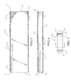
- FIG. 3 shows a segmented section view of the ramp 9 ( d ) in accordance with the view produced by section line 3 - 3 of FIG. 2 .
- FIG. 4 presents a front section view of one of the ramps 9 ( a ) in accordance with the view resulting from section line 4 - 4 of FIG. 2 .
- FIG. 5 presents a plan view of a bridge 8 ( d ) in accordance with the section line 5 - 5 of FIG. 7 .
- FIG. 6 illustrates a side section view of the bridge 8 ( d ) of FIG. 5 as depicted resulting from section line 6 - 6 or FIG. 7 .
- FIG. 7 depicts a from view of the full bridge 8 ( d ), further showing the left stop block 12 and right stop block 13 , and the rod guide tube 27 .
- FIG. 8 illustrates a “peel-away” plan view of one of the bedrunners 7 ( d ), further showing the internal travel rod 25 .
- FIG. 9 is a sidewise section view of the bedrunner 7 ( d ) of FIG. 8 , as revealed by section line 9 - 9 of FIG. 10 , and further showing the travel rod 25 .
- FIG. 10 is a frontal view of the bedrunner 7 ( d ) of FIG. 8 .
- FIG. 11 presents a plan view of a lengthwise segment of the ramp loading system 1 displaying the connecting pattern of nestling comprising a bedrunner 7 ( a ), a bridge 8 ( a ), and a partially extended ramp 9 ( a ).
- FIG. 11(A) depicts an expanded view of the end of the imbedded bridge 8 ( a ) as the rod guide tube 27 engages the stop nut 29 of the travel rod 25 .
- FIG. 12 is the side view of a ramp 9 ( a ) having been extended and rotated downward in preparation for loading or unloading cargo; the bridge 8 ( a ) remains horizontal, with the ramp hinge pivot bar 24 pivot pin abutting the ramp stop blocks, 12 , 13 which serve to limit ramp 9 ( a ) travel extension.
- FIG. 1 depicts the preferred embodiment of the ramp loading system 1 , having four lengthwise sections. Visible are four housing sections, termed “bedrunners” 9 ( a ), 9 ( b ), 9 ( c ), and 9 ( d ). Each bedrunner 9 ( a )- 9 ( d ) encompasses a bridge, and each bridge encompasses a ramp.
- the rightmost section of the displayed ramp loading system 1 depicts a bed runner 7 ( d ), a bridge 8 ( d ) and a fully deployed ramp 9 ( d ).
- the ramp 9 ( d ) shown has been deployed to make contact with the ground 52 or other surface upon which the truck 6 is parked. A portion of the deployed ramp 9 ( d ) previously had been stored within its associated bridge 8 ( d ), and the bridge 8 ( d ) in turn had been tally nestled within the bedrunner 7 ( d ).
- a bridge stop nut 29 (ref. FIG. 8 , FIG. 11A ) affixed to the interior of the bedrunner 7 ( d ), prevented further extraction of the bridge 8 ( d ).
- the bridge 8 ( d ) covers the horizontal length of the tailgate 5 of the truck 6 and serves to prevent undue contact with or damage to the tailgate 5 .
- the remaining three ramps 9 ( b ), 9 ( c ), 9 ( d ), may also be extended.
- FIG. 2 a more detailed depiction of the structure and mechanism associated with a typical ramp 9 ( d ) is shown.
- the rightmost ramp 9 ( d ) of FIG. 1 is shown and depicted by means of its plan view.
- the ramp 9 ( d ) hinge end 71 is the general location of vertical attachment of a support beam 73 between the interior of the top surface 16 and the interior bottom surface 19 .
- a bracket 74 is attached to the support beam 73 by means of bolts 75 .
- a horizontally-oriented hinge pivot bar 24 is then securely affixed to the bracket 74 (also shown in FIG. 3 ).
- the ramp front end 70 is the point of attachment of a handle 20 having a recessed opening 21 for ease of grasping.
- FIG. 3 is a section view of the left side of the ramp 9 ( d ), as displayed with respect to section line 3 - 3 of FIG. 2 .
- the support bean 73 attached to the interior surfaces of the ramp top 16 and ramp bottom 19 of the ramp 9 ( d ).
- the bracket 74 is shown attached by bolts 75 .
- the hinge pivot bar 24 is orthogonally welded to the rear end of the bracket 74 .
- the two bolts 75 may be loosened and thereby allow the slidable positioning of the bracket 74 horizontally, if necessary.
- the variable positioning of the bracket 74 permits the deployment of the ramp 10 at a variety of downward angles for cargo loading and further helps the ramp 9 ( d ) in clearing the tailgate 5 of a truck, if present.
- the function and structure of the ramp 9 ( d ) shown in FIG. 2 and FIG. 3 is identical to that of the remaining ramps 9 ( a ), 9 ( b ), 9 ( c ), which are shown retracted and stowed in FIG. 1 .
- FIG. 4 depicts a cross-sectional view of the front portion of the ramp 9 ( d ), in accordance with the orientation of section line 4 - 4 of FIG. 2 .
- An upper left flange 17 and an upper right flange 18 are shown, both of which help impart rigidity to the ramp 9 ( d ).
- Both flanges 17 , 18 extend the entire length of the ramp 9 ( d ), while the right flange 18 provides vertical clearance over a rod guide tube 27 attached to the right sidewall of the corresponding bridge 8 ( d ).
- the rod guide tube 27 is illustrated more clearly in FIG. 5 and FIG. 6 .
- the top surface 16 of the ramp 9 ( d ) shown in FIG. 2 may be fabricated with a non-slip coating for footing safety and better traction for wheeled cargo items.
- the front end 62 of the rightmost bridge 8 ( d ) of FIG. 1 is discussed as shown in FIG. 7 .
- the function and structure of this bridge 8 ( d ) is identical to that of the remaining bridges 8 ( a ), 8 ( b ), 8 ( c ) which are out of view, but housed within the confines of bedrunners 7 ( a ), 7 ( b ), 7 ( c ) of FIG. 1 .
- the front end 62 of the bridge 8 ( d ) is hollow as to allow horizontal passage of its corresponding ramp 9 ( d ) horizontally back-and-forth during normal operation of the ramp loading system 1 .
- the rod guide tube 27 is also shown in FIG. 7 as it is welded 36 to the right wall of the bridge 8 ( d ), the left stop block 12 , and right stop block 13 .
- FIG. 5 there is illustrated a sectional plan view of the bridge 8 ( d ) in accordance with section line 5 - 5 of FIG. 7 .
- the left and right stop blocks 12 , 13 which serve to engage the hinge pivot bar 24 at the front end 70 of the corresponding ramp 9 ( d ) during horizontal travel back and forth.
- the left and right stop blocks 12 , 13 are welded 36 to the interior sides of the bridge 8 ( d ), as shown in FIG. 5 .
- the rod guide tube 27 is also shown with a plurality of welds 36 attaching it to the right side wall of the ramp 8 ( d ).
- the rod guide tube 27 has a cap 28 which engages a bridge stop nut 29 (shown in FIG. 8 and FIG. 9 ), which stop nut 29 is affixed to the travel rod 25 of the associated bedrunner 7 ( d ).
- FIG. 6 depicts a sectional view of the left side of bridge 8 ( d ) in accordance with section line 6 - 6 of FIG. 7 .
- the left stop block 12 Toward the front end 62 of the bridge 8 ( d ) is shown the left stop block 12 .
- the rod guide tube 27 is also shown along with the guide tube cap 28 .
- the front end 62 of the rightmost bridge 8 ( d ) of FIG. 1 is depicted in FIG. 7 .
- this bridge 8 ( d ) is identical to that of the remaining bridges 8 ( a ), 8 ( b ), 8 ( c ) which are out of view, but housed within the confines of bedrunners 7 ( a ), 7 ( b ), 7 ( c ) illustrated in FIG. 1 . Also shown in FIG. 7 is the rod guide tube 27 as it is welded 36 to the right wall of the bridge 8 ( d ), the left stop block 12 , and right stop block 13 .
- the from end 62 of the bridge 8 ( d ) is open so as to allow horizontal passage of its corresponding ramp 9 ( d ) to and fro during normal operation of the ramp loading system 1 .
- the interior dimensions and contour of the bridge 8 ( d ) are accurately designed and fabricated to accommodate passage and nestling of the exterior dimensions and contour of its associated ramp 9 ( d ).
- the function and structure of this bridge 8 ( d ) are identical to that of the remaining bridges 8 ( a ), 8 ( b ), 8 ( c ) (which are not in view in FIG. 1 ).
- FIG. 8 there is illustrated a sectional plan view of the bedrunner 7 ( d ) which structurally corresponds to the previously-described bridge 8 ( d ).
- the front end 60 of the rightmost bedrunner 7 ( d ) of FIG. 1 is discussed.
- FIG. 8 is shown in accordance with section lines 8 - 8 of FIG. 10 .
- the front end 60 of the bedrunner 7 ( d ) is open so as to allow horizontal passage of its corresponding bridge 8 ( d ) back and forth during normal operation of the ramp loading system 1 .
- Also shown in FIG. 8 is the travel rod 25 , and its corresponding bridge stop nut 29 , the rear portion of the travel rod 25 being welded 36 to the right wall of the bedrunner 7 ( d ).
- FIG. 9 illustrates a sectional view of the left side of the bedrunner 7 ( d ) in accordance with section line 9 - 9 of FIG. 10 .
- the bedrunner 7 ( d ) may be secured to the bed of a pickup truck or other surface by attachment at the undersurface 59 of the bedrunner 7 ( d ) or at the back end 61 of the bedrunner 7 ( d ).
- the function and structure of the bedrunner 7 ( d ) under discussion is identical to that of the remaining bedrunners 7 ( a ), 7 ( b ), 7 ( c ) which are depicted in the preferred embodiment of FIG. 1 .
- the interior dimensions and contour of the bedrunner 7 ( d ) are accurately designed and fabricated to accommodate through-passage and nestling of the exterior dimensions and contour of its associated bridge 8 ( d ).
- FIG. 11 depicts the relative extension-retraction operation of the leftmost ramp 9 ( a ), its bridge 8 ( a ), and the bedrunner 7 ( a ).
- a user initiates the procedure by grasping the recessed opening 21 of the ramp handle 20 and pulling horizontally outward.
- the ramp 9 ( a ) moves outward from its stowage inside the bridge 8 ( a ) and eventually the hinge pivot bar 24 makes contact with the vertically-oriented left and right stop blocks 12 , 13 attached to the interior walls of the bridge 8 ( a ). This contact causes the bridge 8 ( a ) to be extracted from its nestling position inside the bedrunner 7 ( a ).
- These three segments of the ramp loading system 1 respectively depict the telescopic manner of nestling, with sufficient lateral and longitudinal clearance, of the bedrunner 7 ( a ), bridge 8 ( a ), and ramp 9 ( a ), from left to right.
- FIG. 11A is a close-up view of the manner in which the end cap 28 of the rod guide tube 27 of the bridge 8 ( a ) engages the bridge stop nut 29 .
- the bridge stop not 29 is coupled with the threaded travel rod 25 .
- the bridge 8 ( a ) is prevented from any further lengthwise extraction from the bedrunner 7 ( a ).
- FIG. 12 shows the stage wherein the ramp 9 ( a ) has been pulled from the bridge 8 ( a ) to the limit of its travel from without the bedrunner 7 ( a ). Also, the hinge pivot bar 24 is shown abutting the left and right stop blocks 12 , 13 . At this point, a user lowers the ramp 9 ( a ) and this action causes the hinge pivot bar 24 to move slightly upward, rotating the back end 71 of the ramp. The hinge pivot bar 24 then is stabilized in position against the stop blocks 12 , 13 . In turn, the handle 20 of the ramp 9 ( a ) makes contact with the ground 52 or other surface.
- the user grasps the handle 20 , pulls the ramp 9 ( a ) upward to a horizontal orientation, then pushes the ramp 9 ( a ), into the back end 63 of the bridge 8 ( a ). Continuation of the pushing motion causes both the bridge 8 ( a ) and ramp 9 ( a ) to retract into the bedrunner 7 ( a ).
Landscapes
- Engineering & Computer Science (AREA)
- Transportation (AREA)
- Mechanical Engineering (AREA)
- Chemical & Material Sciences (AREA)
- Combustion & Propulsion (AREA)
- Body Structure For Vehicles (AREA)
Abstract
Description
| Nomenclature For Invention Components |
| 1. | |
||
| 2. | |
||
| 3. | |
||
| 4. | Truck back wall | ||
| 5. | Tailgate | ||
| 6. | Pickup truck | ||
| 7(a) | First bedrunner | ||
| 7(b) | Second bedrunner | ||
| 7(c) | Third bedrunner | ||
| 7(d) | Fourth bedrunner | ||
| 8(a) | First bridge | ||
| 8(b) | Second bridge | ||
| 8(c) | Third bridge | ||
| 8(d) | Fourth bridge | ||
| 9(a) | First ramp | ||
| 9(b) | Second ramp | ||
| 9(c) | Third ramp | ||
| 9(d) | Fourth ramp | ||
| 10.-11. | n/a | ||
| 12. | |
||
| 13. | |
||
| 14. | Ramp left |
||
| 15. | Ramp |
||
| 16. | Ramp |
||
| 17. | Ramp left |
||
| 18. | Ramp |
||
| 19. | |
||
| 20. | |
||
| 21. | Recessed opening | ||
| 22.-23. | n/a | ||
| 24. | |
||
| 25. | Travel rod | ||
| 26. | |
||
| 27. | |
||
| 28. | |
||
| 29. | Bridge stop nut | ||
| 30.-32. | n/a | ||
| 33. | Bridge |
||
| 34. | Bridge lower surface | ||
| 35. | n/a | ||
| 36. | Weld | ||
| 37.-49. | n/a | ||
| 50. | Ramp stabilizer | ||
| 51. | |
||
| 52. | Surface or ground | ||
| 53.-57. | n/a | ||
| 58. | |
||
| 59. | |
||
| 60. | Bedrunner |
||
| 61. | Bedrunner |
||
| 62. | Bridge |
||
| 63. | Bridge |
||
| 70. | Ramp |
||
| 71. | Ramp back end | ||
| 72. | n/a | ||
| 73. | |
||
| 74. | I- |
||
| 75. | Bolt | ||
| 76. | n/a | ||
Claims (14)
Priority Applications (1)
| Application Number | Priority Date | Filing Date | Title |
|---|---|---|---|
| US15/687,515 US10017092B1 (en) | 2017-08-27 | 2017-08-27 | Adjustable truckbed with extendable ramp |
Applications Claiming Priority (1)
| Application Number | Priority Date | Filing Date | Title |
|---|---|---|---|
| US15/687,515 US10017092B1 (en) | 2017-08-27 | 2017-08-27 | Adjustable truckbed with extendable ramp |
Publications (1)
| Publication Number | Publication Date |
|---|---|
| US10017092B1 true US10017092B1 (en) | 2018-07-10 |
Family
ID=62750287
Family Applications (1)
| Application Number | Title | Priority Date | Filing Date |
|---|---|---|---|
| US15/687,515 Expired - Fee Related US10017092B1 (en) | 2017-08-27 | 2017-08-27 | Adjustable truckbed with extendable ramp |
Country Status (1)
| Country | Link |
|---|---|
| US (1) | US10017092B1 (en) |
Cited By (8)
| Publication number | Priority date | Publication date | Assignee | Title |
|---|---|---|---|---|
| US20180334071A1 (en) * | 2017-05-16 | 2018-11-22 | Ford Global Technologies, Llc | Truck bed loading system |
| US10994761B2 (en) * | 2019-03-20 | 2021-05-04 | Susan Chappell | Low profile cart with access ramp |
| US20210206307A1 (en) * | 2020-01-07 | 2021-07-08 | Brooke Martinson | Truck ramp system and method |
| US20220009417A1 (en) * | 2020-07-07 | 2022-01-13 | Hyundai Motor Company | Cargo bed assembly for pickup truck |
| CN113928207A (en) * | 2021-09-29 | 2022-01-14 | 广州雷军机械设备有限公司 | Vehicle-mounted motorcycle transportation frame |
| US20230256910A1 (en) * | 2022-02-17 | 2023-08-17 | Ford Global Technologies, Llc | Deployable step for vehicle with extendable cargo bed |
| US11753086B2 (en) | 2022-02-17 | 2023-09-12 | Ford Global Technologies, Llc | Ramp system for vehicle with extendable cargo bed |
| US11926201B1 (en) * | 2018-02-27 | 2024-03-12 | Michael A. Lillo | School bus emergency egress system |
Citations (27)
| Publication number | Priority date | Publication date | Assignee | Title |
|---|---|---|---|---|
| US4601632A (en) * | 1984-12-10 | 1986-07-22 | Agee John H | Stowable truck ramp with extension sleeve |
| US5257894A (en) | 1992-04-23 | 1993-11-02 | Grant Howard K | Small vehicle stowable ramp system |
| US5468114A (en) | 1994-06-20 | 1995-11-21 | Hickerson; Scott J. | Loading device for pick-up trucks |
| US5597195A (en) | 1995-06-02 | 1997-01-28 | Meek; Keith C. | Rampable tailgate |
| US6042923A (en) * | 1997-11-19 | 2000-03-28 | Lewis; Robert P. | Ramp assembly for all-terrain vehicles |
| US6059344A (en) * | 1999-08-12 | 2000-05-09 | Radosevich; Vincent | Pickup tailgate ramp |
| US20040009055A1 (en) | 2001-03-26 | 2004-01-15 | Scherle Jerry A. | Tilting ramp for transport of personal recreational vehicles |
| US6705820B2 (en) | 2000-04-25 | 2004-03-16 | Hms Lift, Llc | Carrier/lift for a truck bed |
| US20040219004A1 (en) | 2000-12-29 | 2004-11-04 | Huggins George M. | Pickup tailgate loading ramp |
| US20040223836A1 (en) | 2003-05-06 | 2004-11-11 | Robertson Ronald I. | Vehicle ramp assembly |
| US20040226116A1 (en) * | 2003-05-13 | 2004-11-18 | O'donnell Michael R. | Portable ramp assembly |
| US20060245883A1 (en) | 2005-04-11 | 2006-11-02 | Yves Fontaine | Vehicle ramp assembly |
| US20070237614A1 (en) * | 2006-04-06 | 2007-10-11 | Johnson Robert A | Ramp apparatus for use with an automotive vehicle |
| US7309202B1 (en) | 2004-12-01 | 2007-12-18 | Anderson Michael D | Combination loading ramp/extension table for a truck bed |
| US20080159838A1 (en) | 2006-04-05 | 2008-07-03 | Bradley Yates Sherer | Cargo area extending foldable loading ramp |
| US7488025B1 (en) * | 2006-07-28 | 2009-02-10 | Roberson Andrew M | Truck bed extender and telescoping ramp |
| US7524156B2 (en) | 2005-02-04 | 2009-04-28 | Larry Vern Garbes | Portable and stowable ramp and equipment storage system for pickup trucks |
| US7549692B2 (en) | 2007-10-31 | 2009-06-23 | Washington Derron K | Ramp assembly for a vehicle tailgate |
| US7810196B1 (en) | 2008-04-10 | 2010-10-12 | Tyler Pritchard | Independently extendable truck ramps and associated use therefor |
| US20100266378A1 (en) | 2009-04-16 | 2010-10-21 | Paul Verwys | Loading device |
| US20110072596A1 (en) | 2008-03-07 | 2011-03-31 | Mark Kenny | Extendable ramp for storage in a tailgate or flat bed |
| US7976264B1 (en) | 2008-08-13 | 2011-07-12 | Pope Timothy W | Truck bed apparatus |
| US20130294873A1 (en) * | 2012-05-04 | 2013-11-07 | Robert M. Chastain, JR. | Cargo and vehicle ramp loading system |
| US20140356117A1 (en) * | 2013-05-28 | 2014-12-04 | William Barger | Storable Truck Ramp |
| US20160059763A1 (en) * | 2014-08-29 | 2016-03-03 | Michael J. Sindoni, JR. | Retractable bed ramps with platform for a pickup truck |
| US20170174113A1 (en) * | 2015-12-17 | 2017-06-22 | GM Global Technology Operations LLC | Loading ramp assembly and a movable cargo transport including the loading ramp assembly |
| US20170267150A1 (en) * | 2016-03-17 | 2017-09-21 | Allan Bergen | Truck ramp for pickup trucks |
-
2017
- 2017-08-27 US US15/687,515 patent/US10017092B1/en not_active Expired - Fee Related
Patent Citations (28)
| Publication number | Priority date | Publication date | Assignee | Title |
|---|---|---|---|---|
| US4601632A (en) * | 1984-12-10 | 1986-07-22 | Agee John H | Stowable truck ramp with extension sleeve |
| US5257894A (en) | 1992-04-23 | 1993-11-02 | Grant Howard K | Small vehicle stowable ramp system |
| US5468114A (en) | 1994-06-20 | 1995-11-21 | Hickerson; Scott J. | Loading device for pick-up trucks |
| US5597195A (en) | 1995-06-02 | 1997-01-28 | Meek; Keith C. | Rampable tailgate |
| US6042923A (en) * | 1997-11-19 | 2000-03-28 | Lewis; Robert P. | Ramp assembly for all-terrain vehicles |
| US6059344A (en) * | 1999-08-12 | 2000-05-09 | Radosevich; Vincent | Pickup tailgate ramp |
| US6705820B2 (en) | 2000-04-25 | 2004-03-16 | Hms Lift, Llc | Carrier/lift for a truck bed |
| US20040219004A1 (en) | 2000-12-29 | 2004-11-04 | Huggins George M. | Pickup tailgate loading ramp |
| US20040009055A1 (en) | 2001-03-26 | 2004-01-15 | Scherle Jerry A. | Tilting ramp for transport of personal recreational vehicles |
| US20040223836A1 (en) | 2003-05-06 | 2004-11-11 | Robertson Ronald I. | Vehicle ramp assembly |
| US20040226116A1 (en) * | 2003-05-13 | 2004-11-18 | O'donnell Michael R. | Portable ramp assembly |
| US7309202B1 (en) | 2004-12-01 | 2007-12-18 | Anderson Michael D | Combination loading ramp/extension table for a truck bed |
| US7524156B2 (en) | 2005-02-04 | 2009-04-28 | Larry Vern Garbes | Portable and stowable ramp and equipment storage system for pickup trucks |
| US20060245883A1 (en) | 2005-04-11 | 2006-11-02 | Yves Fontaine | Vehicle ramp assembly |
| US20080159838A1 (en) | 2006-04-05 | 2008-07-03 | Bradley Yates Sherer | Cargo area extending foldable loading ramp |
| US20070237614A1 (en) * | 2006-04-06 | 2007-10-11 | Johnson Robert A | Ramp apparatus for use with an automotive vehicle |
| US7488025B1 (en) * | 2006-07-28 | 2009-02-10 | Roberson Andrew M | Truck bed extender and telescoping ramp |
| US7549692B2 (en) | 2007-10-31 | 2009-06-23 | Washington Derron K | Ramp assembly for a vehicle tailgate |
| US20110072596A1 (en) | 2008-03-07 | 2011-03-31 | Mark Kenny | Extendable ramp for storage in a tailgate or flat bed |
| US7810196B1 (en) | 2008-04-10 | 2010-10-12 | Tyler Pritchard | Independently extendable truck ramps and associated use therefor |
| US7976264B1 (en) | 2008-08-13 | 2011-07-12 | Pope Timothy W | Truck bed apparatus |
| US20100266378A1 (en) | 2009-04-16 | 2010-10-21 | Paul Verwys | Loading device |
| US20130294873A1 (en) * | 2012-05-04 | 2013-11-07 | Robert M. Chastain, JR. | Cargo and vehicle ramp loading system |
| US9073475B2 (en) * | 2012-05-04 | 2015-07-07 | Robert M. Chastain, JR. | Cargo and vehicle ramp loading system |
| US20140356117A1 (en) * | 2013-05-28 | 2014-12-04 | William Barger | Storable Truck Ramp |
| US20160059763A1 (en) * | 2014-08-29 | 2016-03-03 | Michael J. Sindoni, JR. | Retractable bed ramps with platform for a pickup truck |
| US20170174113A1 (en) * | 2015-12-17 | 2017-06-22 | GM Global Technology Operations LLC | Loading ramp assembly and a movable cargo transport including the loading ramp assembly |
| US20170267150A1 (en) * | 2016-03-17 | 2017-09-21 | Allan Bergen | Truck ramp for pickup trucks |
Cited By (11)
| Publication number | Priority date | Publication date | Assignee | Title |
|---|---|---|---|---|
| US20180334071A1 (en) * | 2017-05-16 | 2018-11-22 | Ford Global Technologies, Llc | Truck bed loading system |
| US11926201B1 (en) * | 2018-02-27 | 2024-03-12 | Michael A. Lillo | School bus emergency egress system |
| US10994761B2 (en) * | 2019-03-20 | 2021-05-04 | Susan Chappell | Low profile cart with access ramp |
| US11834088B2 (en) * | 2019-03-20 | 2023-12-05 | Susan Chappell | Low profile cart for large animals |
| US20210206307A1 (en) * | 2020-01-07 | 2021-07-08 | Brooke Martinson | Truck ramp system and method |
| US20220009417A1 (en) * | 2020-07-07 | 2022-01-13 | Hyundai Motor Company | Cargo bed assembly for pickup truck |
| US11505129B2 (en) * | 2020-07-07 | 2022-11-22 | Hyundai Motor Company | Cargo bed assembly for pickup truck |
| CN113928207A (en) * | 2021-09-29 | 2022-01-14 | 广州雷军机械设备有限公司 | Vehicle-mounted motorcycle transportation frame |
| US20230256910A1 (en) * | 2022-02-17 | 2023-08-17 | Ford Global Technologies, Llc | Deployable step for vehicle with extendable cargo bed |
| US11753086B2 (en) | 2022-02-17 | 2023-09-12 | Ford Global Technologies, Llc | Ramp system for vehicle with extendable cargo bed |
| US11951948B2 (en) * | 2022-02-17 | 2024-04-09 | Ford Global Technologies, Llc | Deployable step for vehicle with extendable cargo bed |
Similar Documents
| Publication | Publication Date | Title |
|---|---|---|
| US10017092B1 (en) | Adjustable truckbed with extendable ramp | |
| US9073475B2 (en) | Cargo and vehicle ramp loading system | |
| US12319234B2 (en) | Vehicle mounted accessory | |
| US7168722B1 (en) | Pull-out step assembly for a pickup truck | |
| CN110650867B (en) | Hitch-mounted carrying systems with ramps | |
| US5090335A (en) | Table for truck bed | |
| US7549692B2 (en) | Ramp assembly for a vehicle tailgate | |
| US4864673A (en) | Folding ramp | |
| US5257894A (en) | Small vehicle stowable ramp system | |
| US10464618B2 (en) | Truck bed extender formed by a retractable tailgate step and handles | |
| US6722721B2 (en) | Pickup truck foldable ramp tailgate | |
| US9199569B2 (en) | Telescoping and magnetic tailgate ramp | |
| US6340190B1 (en) | Tailgate attachment for extending the cargo space of a vehicle | |
| US7758091B1 (en) | Collapsible ladder rack system for vehicles | |
| US10131384B2 (en) | Truck bed extender with webbing | |
| US5026243A (en) | Portable unloading platform and ramp | |
| US20200223465A1 (en) | Collapsible locomotion platform and cart | |
| US10086775B2 (en) | Vehicle tailgate with integrated sawhorse | |
| US11643125B2 (en) | Dolly for attachment to a vehicle hitch | |
| US8882436B2 (en) | ATV ramp | |
| US9266458B2 (en) | Foldable extension deck and ramp assembly for pickup truck | |
| US11420696B2 (en) | Vertically stowable trailer | |
| AU2013200918A1 (en) | Hitch Mounted Camping Assembly | |
| US6379101B1 (en) | Ramp and cargo system | |
| AU2015200661B2 (en) | Trailer Loading Apparatus and Method |
Legal Events
| Date | Code | Title | Description |
|---|---|---|---|
| FEPP | Fee payment procedure |
Free format text: ENTITY STATUS SET TO UNDISCOUNTED (ORIGINAL EVENT CODE: BIG.); ENTITY STATUS OF PATENT OWNER: MICROENTITY |
|
| FEPP | Fee payment procedure |
Free format text: ENTITY STATUS SET TO SMALL (ORIGINAL EVENT CODE: SMAL); ENTITY STATUS OF PATENT OWNER: MICROENTITY Free format text: ENTITY STATUS SET TO MICRO (ORIGINAL EVENT CODE: MICR); ENTITY STATUS OF PATENT OWNER: MICROENTITY |
|
| STCF | Information on status: patent grant |
Free format text: PATENTED CASE |
|
| FEPP | Fee payment procedure |
Free format text: MAINTENANCE FEE REMINDER MAILED (ORIGINAL EVENT CODE: REM.); ENTITY STATUS OF PATENT OWNER: MICROENTITY |
|
| FEPP | Fee payment procedure |
Free format text: SURCHARGE, PETITION TO ACCEPT PYMT AFTER EXP, UNINTENTIONAL (ORIGINAL EVENT CODE: M3558); ENTITY STATUS OF PATENT OWNER: MICROENTITY Free format text: PETITION RELATED TO MAINTENANCE FEES FILED (ORIGINAL EVENT CODE: PMFP); ENTITY STATUS OF PATENT OWNER: MICROENTITY |
|
| MAFP | Maintenance fee payment |
Free format text: PAYMENT OF MAINTENANCE FEE, 4TH YEAR, MICRO ENTITY (ORIGINAL EVENT CODE: M3551); ENTITY STATUS OF PATENT OWNER: MICROENTITY Year of fee payment: 4 |
|
| LAPS | Lapse for failure to pay maintenance fees |
Free format text: PATENT EXPIRED FOR FAILURE TO PAY MAINTENANCE FEES (ORIGINAL EVENT CODE: EXP.); ENTITY STATUS OF PATENT OWNER: MICROENTITY |
|
| STCH | Information on status: patent discontinuation |
Free format text: PATENT EXPIRED DUE TO NONPAYMENT OF MAINTENANCE FEES UNDER 37 CFR 1.362 |
|
| FP | Lapsed due to failure to pay maintenance fee |
Effective date: 20220710 |
|
| FEPP | Fee payment procedure |
Free format text: PETITION RELATED TO MAINTENANCE FEES DISMISSED (ORIGINAL EVENT CODE: PMFS); ENTITY STATUS OF PATENT OWNER: MICROENTITY |