US10016972B2 - Coating for aqueous inkjet transfer - Google Patents
Coating for aqueous inkjet transfer Download PDFInfo
- Publication number
- US10016972B2 US10016972B2 US15/142,516 US201615142516A US10016972B2 US 10016972 B2 US10016972 B2 US 10016972B2 US 201615142516 A US201615142516 A US 201615142516A US 10016972 B2 US10016972 B2 US 10016972B2
- Authority
- US
- United States
- Prior art keywords
- ink
- itm
- skin
- image transfer
- image
- Prior art date
- Legal status (The legal status is an assumption and is not a legal conclusion. Google has not performed a legal analysis and makes no representation as to the accuracy of the status listed.)
- Active
Links
- 238000012546 transfer Methods 0.000 title claims abstract description 62
- 238000000576 coating method Methods 0.000 title description 12
- 239000011248 coating agent Substances 0.000 title description 9
- PEDCQBHIVMGVHV-UHFFFAOYSA-N glycerol group Chemical group OCC(O)CO PEDCQBHIVMGVHV-UHFFFAOYSA-N 0.000 claims abstract description 45
- 239000003230 hygroscopic agent Substances 0.000 claims abstract description 24
- XLYOFNOQVPJJNP-UHFFFAOYSA-N water Substances O XLYOFNOQVPJJNP-UHFFFAOYSA-N 0.000 claims abstract description 12
- 239000000203 mixture Substances 0.000 claims description 30
- 239000003795 chemical substances by application Substances 0.000 claims description 15
- 229920002472 Starch Polymers 0.000 claims description 9
- 239000008107 starch Substances 0.000 claims description 9
- 235000019698 starch Nutrition 0.000 claims description 9
- 239000011118 polyvinyl acetate Substances 0.000 claims description 3
- 229920002449 FKM Polymers 0.000 claims description 2
- 239000004809 Teflon Substances 0.000 claims description 2
- 229920006362 Teflon® Polymers 0.000 claims description 2
- 229920001296 polysiloxane Polymers 0.000 claims description 2
- 229920002689 polyvinyl acetate Polymers 0.000 claims description 2
- BFKJFAAPBSQJPD-UHFFFAOYSA-N tetrafluoroethene Chemical compound FC(F)=C(F)F BFKJFAAPBSQJPD-UHFFFAOYSA-N 0.000 claims description 2
- 238000000034 method Methods 0.000 abstract description 10
- 230000008569 process Effects 0.000 abstract description 7
- 238000001035 drying Methods 0.000 abstract description 6
- 239000000976 ink Substances 0.000 description 81
- 239000000758 substrate Substances 0.000 description 22
- 238000003892 spreading Methods 0.000 description 16
- 230000007480 spreading Effects 0.000 description 16
- 239000008199 coating composition Substances 0.000 description 10
- 238000007639 printing Methods 0.000 description 10
- 238000001000 micrograph Methods 0.000 description 8
- 239000011230 binding agent Substances 0.000 description 6
- 239000000463 material Substances 0.000 description 6
- 238000003384 imaging method Methods 0.000 description 5
- 239000010410 layer Substances 0.000 description 5
- 238000009736 wetting Methods 0.000 description 4
- LYCAIKOWRPUZTN-UHFFFAOYSA-N Ethylene glycol Chemical compound OCCO LYCAIKOWRPUZTN-UHFFFAOYSA-N 0.000 description 3
- 238000009835 boiling Methods 0.000 description 3
- 238000004581 coalescence Methods 0.000 description 3
- 238000010586 diagram Methods 0.000 description 3
- 238000001704 evaporation Methods 0.000 description 3
- 230000008020 evaporation Effects 0.000 description 3
- 239000004094 surface-active agent Substances 0.000 description 3
- 230000006870 function Effects 0.000 description 2
- 238000007641 inkjet printing Methods 0.000 description 2
- 239000007788 liquid Substances 0.000 description 2
- 238000004381 surface treatment Methods 0.000 description 2
- MIDXCONKKJTLDX-UHFFFAOYSA-N 3,5-dimethylcyclopentane-1,2-dione Chemical compound CC1CC(C)C(=O)C1=O MIDXCONKKJTLDX-UHFFFAOYSA-N 0.000 description 1
- 238000010521 absorption reaction Methods 0.000 description 1
- 230000009471 action Effects 0.000 description 1
- 238000007774 anilox coating Methods 0.000 description 1
- 238000013459 approach Methods 0.000 description 1
- 230000004888 barrier function Effects 0.000 description 1
- 230000008901 benefit Effects 0.000 description 1
- 235000013736 caramel Nutrition 0.000 description 1
- 230000008859 change Effects 0.000 description 1
- 238000004140 cleaning Methods 0.000 description 1
- 239000003086 colorant Substances 0.000 description 1
- 238000013329 compounding Methods 0.000 description 1
- 230000007547 defect Effects 0.000 description 1
- 238000013461 design Methods 0.000 description 1
- 230000000694 effects Effects 0.000 description 1
- 230000002708 enhancing effect Effects 0.000 description 1
- 239000012530 fluid Substances 0.000 description 1
- -1 fluorosilicone Polymers 0.000 description 1
- 235000011187 glycerol Nutrition 0.000 description 1
- 238000010438 heat treatment Methods 0.000 description 1
- 235000012907 honey Nutrition 0.000 description 1
- 230000006872 improvement Effects 0.000 description 1
- 239000004615 ingredient Substances 0.000 description 1
- 230000014759 maintenance of location Effects 0.000 description 1
- 230000007246 mechanism Effects 0.000 description 1
- 238000012986 modification Methods 0.000 description 1
- 230000004048 modification Effects 0.000 description 1
- 229920002635 polyurethane Polymers 0.000 description 1
- 239000004814 polyurethane Substances 0.000 description 1
- 238000012805 post-processing Methods 0.000 description 1
- 239000002243 precursor Substances 0.000 description 1
- CMDGQTVYVAKDNA-UHFFFAOYSA-N propane-1,2,3-triol;hydrate Chemical compound O.OCC(O)CO CMDGQTVYVAKDNA-UHFFFAOYSA-N 0.000 description 1
- 230000009467 reduction Effects 0.000 description 1
- 239000011347 resin Substances 0.000 description 1
- 229920005989 resin Polymers 0.000 description 1
- 230000000717 retained effect Effects 0.000 description 1
- 239000002356 single layer Substances 0.000 description 1
- 239000007787 solid Substances 0.000 description 1
- 239000002904 solvent Substances 0.000 description 1
- 235000000346 sugar Nutrition 0.000 description 1
- 239000006188 syrup Substances 0.000 description 1
- 235000020357 syrup Nutrition 0.000 description 1
Images


Classifications
-
- B—PERFORMING OPERATIONS; TRANSPORTING
- B41—PRINTING; LINING MACHINES; TYPEWRITERS; STAMPS
- B41J—TYPEWRITERS; SELECTIVE PRINTING MECHANISMS, i.e. MECHANISMS PRINTING OTHERWISE THAN FROM A FORME; CORRECTION OF TYPOGRAPHICAL ERRORS
- B41J2/00—Typewriters or selective printing mechanisms characterised by the printing or marking process for which they are designed
- B41J2/005—Typewriters or selective printing mechanisms characterised by the printing or marking process for which they are designed characterised by bringing liquid or particles selectively into contact with a printing material
- B41J2/0057—Typewriters or selective printing mechanisms characterised by the printing or marking process for which they are designed characterised by bringing liquid or particles selectively into contact with a printing material where an intermediate transfer member receives the ink before transferring it on the printing material
-
- B—PERFORMING OPERATIONS; TRANSPORTING
- B41—PRINTING; LINING MACHINES; TYPEWRITERS; STAMPS
- B41J—TYPEWRITERS; SELECTIVE PRINTING MECHANISMS, i.e. MECHANISMS PRINTING OTHERWISE THAN FROM A FORME; CORRECTION OF TYPOGRAPHICAL ERRORS
- B41J2/00—Typewriters or selective printing mechanisms characterised by the printing or marking process for which they are designed
- B41J2/005—Typewriters or selective printing mechanisms characterised by the printing or marking process for which they are designed characterised by bringing liquid or particles selectively into contact with a printing material
- B41J2/01—Ink jet
- B41J2/21—Ink jet for multi-colour printing
-
- C—CHEMISTRY; METALLURGY
- C09—DYES; PAINTS; POLISHES; NATURAL RESINS; ADHESIVES; COMPOSITIONS NOT OTHERWISE PROVIDED FOR; APPLICATIONS OF MATERIALS NOT OTHERWISE PROVIDED FOR
- C09D—COATING COMPOSITIONS, e.g. PAINTS, VARNISHES OR LACQUERS; FILLING PASTES; CHEMICAL PAINT OR INK REMOVERS; INKS; CORRECTING FLUIDS; WOODSTAINS; PASTES OR SOLIDS FOR COLOURING OR PRINTING; USE OF MATERIALS THEREFOR
- C09D103/00—Coating compositions based on starch, amylose or amylopectin or on their derivatives or degradation products
- C09D103/02—Starch; Degradation products thereof, e.g. dextrin
-
- C—CHEMISTRY; METALLURGY
- C09—DYES; PAINTS; POLISHES; NATURAL RESINS; ADHESIVES; COMPOSITIONS NOT OTHERWISE PROVIDED FOR; APPLICATIONS OF MATERIALS NOT OTHERWISE PROVIDED FOR
- C09D—COATING COMPOSITIONS, e.g. PAINTS, VARNISHES OR LACQUERS; FILLING PASTES; CHEMICAL PAINT OR INK REMOVERS; INKS; CORRECTING FLUIDS; WOODSTAINS; PASTES OR SOLIDS FOR COLOURING OR PRINTING; USE OF MATERIALS THEREFOR
- C09D11/00—Inks
- C09D11/02—Printing inks
- C09D11/10—Printing inks based on artificial resins
- C09D11/106—Printing inks based on artificial resins containing macromolecular compounds obtained by reactions only involving carbon-to-carbon unsaturated bonds
-
- C—CHEMISTRY; METALLURGY
- C09—DYES; PAINTS; POLISHES; NATURAL RESINS; ADHESIVES; COMPOSITIONS NOT OTHERWISE PROVIDED FOR; APPLICATIONS OF MATERIALS NOT OTHERWISE PROVIDED FOR
- C09D—COATING COMPOSITIONS, e.g. PAINTS, VARNISHES OR LACQUERS; FILLING PASTES; CHEMICAL PAINT OR INK REMOVERS; INKS; CORRECTING FLUIDS; WOODSTAINS; PASTES OR SOLIDS FOR COLOURING OR PRINTING; USE OF MATERIALS THEREFOR
- C09D11/00—Inks
- C09D11/02—Printing inks
- C09D11/14—Printing inks based on carbohydrates
-
- C—CHEMISTRY; METALLURGY
- C09—DYES; PAINTS; POLISHES; NATURAL RESINS; ADHESIVES; COMPOSITIONS NOT OTHERWISE PROVIDED FOR; APPLICATIONS OF MATERIALS NOT OTHERWISE PROVIDED FOR
- C09D—COATING COMPOSITIONS, e.g. PAINTS, VARNISHES OR LACQUERS; FILLING PASTES; CHEMICAL PAINT OR INK REMOVERS; INKS; CORRECTING FLUIDS; WOODSTAINS; PASTES OR SOLIDS FOR COLOURING OR PRINTING; USE OF MATERIALS THEREFOR
- C09D11/00—Inks
- C09D11/30—Inkjet printing inks
- C09D11/38—Inkjet printing inks characterised by non-macromolecular additives other than solvents, pigments or dyes
-
- C—CHEMISTRY; METALLURGY
- C09—DYES; PAINTS; POLISHES; NATURAL RESINS; ADHESIVES; COMPOSITIONS NOT OTHERWISE PROVIDED FOR; APPLICATIONS OF MATERIALS NOT OTHERWISE PROVIDED FOR
- C09D—COATING COMPOSITIONS, e.g. PAINTS, VARNISHES OR LACQUERS; FILLING PASTES; CHEMICAL PAINT OR INK REMOVERS; INKS; CORRECTING FLUIDS; WOODSTAINS; PASTES OR SOLIDS FOR COLOURING OR PRINTING; USE OF MATERIALS THEREFOR
- C09D133/00—Coating compositions based on homopolymers or copolymers of compounds having one or more unsaturated aliphatic radicals, each having only one carbon-to-carbon double bond, and at least one being terminated by only one carboxyl radical, or of salts, anhydrides, esters, amides, imides, or nitriles thereof; Coating compositions based on derivatives of such polymers
- C09D133/04—Homopolymers or copolymers of esters
- C09D133/06—Homopolymers or copolymers of esters of esters containing only carbon, hydrogen and oxygen, the oxygen atom being present only as part of the carboxyl radical
Definitions
- present disclosure is generally directed to imaging transfer systems, particularly systems using aqueous ink. More specifically, the disclosure concerns improved coatings for image transfer surfaces.
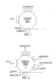
- An image transfer system includes an intermediate transfer member (ITM) to initially receive an image transferred by a plurality of ink jets, as depicted in the diagram of FIG. 1 .
- the ink jets are configured to transfer an aqueous ink onto the surface of the transfer member in a variety of known manners.
- the aqueous image is partially dried before reaching the transfer roll.
- a substrate is pinched between the intermediate transfer member and the transfer roll and the ITM releases the ink image onto the substrate in a transfer step.
- the substrate is conveyed to post-processing components that fix the image onto the substrate. It is understood that the ITM and transfer roll are continuously rotated and that a substrate or substrates are continuously fed through the transfer system and between the ITM and transfer roll.
- Image transfer systems of the kind generically depicted in FIG. 1 are used in a wide range of machines, such as printers, copiers, facsimile machines, book making machines and the like.
- the surface energy of the surface of the ITM controls how well the ink transferred to the ITM surface is retained on the surface and how well the ink image is released from the ITM onto the substrate.
- the problems of ink retention and release are exacerbated in high-throughput systems where the substrate is fed at high speeds through the image transfer system.
- a low surface energy is desirable for optimum image transfer from the surface of the ITM to the surface of the substrate.
- a low surface energy reduces the ability of the aqueous ink to spread on the ITM surface, resulting in a low image quality.
- Aqueous ink jet imaging on a low surface energy, non-absorbing surface and then optimal release and transfer to the substrate has been very challenging, with no commercially viable solution thus far.
- the first challenge wet image quality—prefers a high surface energy on the ITM surface which causes the aqueous ink to spread and wet the surface, rather than beading up into discrete droplets.
- the second challenge image transfer—prefers that the ink, once partially dried on the ITM, has minimal attraction to the ITM surface so that 100% of the ink is transferred from the ITM to the substrate. Thus, image transfer is optimized by minimizing ITM surface energy.
- the third challenge relates to how well the print head can be kept clean of dried ink.
- the drying of the ink on the face plate of a print head can render it inoperable.
- too much moisture can condense on the face plate and cause jetting problems.
- some ink jets can be sensitive to high temperatures, typically temperatures above about 70° C.
- ITM material selection materials that are known to provide optimum release properties include the classes of silicone, fluorosilicone, TEFLON, VITON and certain hybrid materials. These compositions have low surface energy but provide poor wetting. Alternatively, polyurethane and polymide have been used to improve wetting but at the cost of poor ink release properties. Tuning ink compositions to address these challenges has proven to be very difficult since the primary performance attribute of the ink is the performance in the print head.
- ink surface tension is too high it will not jet properly and it if is too low it will drool out of the face plate of the print head.
- Compounding the problem is the fact that for optimal ink transfer, ink cohesion must be significantly greater than the ink-to-ITM adhesion for all image contents, including the stress cases of single layer small dot and three layer process black solid printing.
- the wet image quality is directly affected by surface energy of the ITM.
- low surface energy is typically necessary for image transfer, but this same low surface energy property diminishes the ability of conventional inks, and more particularly aqueous inks, to spread on the ITM surface.
- ink drops coalesce at a state of insufficient spreading, inks from multiple drops can reflow or redistribute in many undesired ways, which ultimately produce image defects.
- the problem of poor-coalescence is enhanced on non-absorbing substrates because there is no simple mechanism to freeze the motion of the colorant in the ink drops. Examples of the poor wet image quality resulting from low surface energy are shown in FIGS. 2 a , 2 b . In the example of FIG.
- the lines of ink should be 100% continuous at 600 dpi with a 12 pl drop size.
- the ink drops draw back due to poor coalescence to that the lines are sporadic and incomplete, again resulting in a poor image quality. Poor ink spreading is the cause of the poor quality in both examples.
- an ink spreading enhancing coating is provided for an indirect image receiving member or blanket in an aqueous printing system in which the coatings include a hygroscopic composition and a surfactant.
- One improved coating composition includes a glycerol composition in a liquid carrier as the hydroscopic composition.
- the improved hygroscopic coating composition is applied to the surface of the blanket and partially dried before the aqueous ink is applied.
- Ink applied in an imagewise manner i.e., according to an image transmitted to the printing device
- the surface of the blanket is then cleaned of any residual hygroscopic coating and ink (if present) and the blanket surface continues to the next application of the improved starch coating composition.
- a coating with improved transfer performance is provided for an indirect image receiving member or blanket in an aqueous printing system in which the coatings include a hygroscopic composition, at least one binder composition (such as starch) and a surfactant.
- the improved hygroscopic coating composition is applied to the surface of the blanket and at least partially dried before the aqueous ink is applied.
- Ink applied in an imagewise manner i.e., according to an image transmitted to the printing device
- the surface of the blanket is then cleaned of any residual of the hygroscopic/binder composition and ink (if present) and the blanket surface continues to the next application of the improved starch coating composition.
- FIG. 1 is a diagram of components of a conventional image transfer system.
- FIG. 2 a is a micrograph of ink drops applied to a low surface energy ITM depicting puddling of the drops.
- FIG. 2 b is a micrograph of ink drops applied to a low surface energy ITM depicting draw-back of the drops due to coalescence.
- FIG. 3 a is a micrograph of ink drops of three volumes (5 pl, 7 pl and 12 pl from left to right) applied to an ink-jet premium photo paper.
- FIG. 3 b is a micrograph of ink drops of three volumes (5 pl, 7 pl and 12 pl from left to right) applied to a skin containing glycerol that has been coated and partially dried on an ITM.
- FIG. 4 a is a micrograph of ink drops of three volumes (5 pl, 7 pl and 12 pl from left to right) applied to a skin that has been coated and partially dried on an ITM, the skin composition has a glycerol-binder ratio of 1:1.
- FIG. 4 b is a micrograph of ink drops of three volumes (5 pl, 7 pl and 12 pl from left to right) applied to a skin that has been coated and partially dried on an ITM, the skin composition has a glycerol-binder ratio of 2:1.
- FIG. 5 is a diagram of an image transfer system, such as the system of FIG. 1 , modified for application of an improved coating composition described herein.
- the present disclosure relates to image transfer systems for transferring an ink image onto a substrate, and particularly to a coating composition for an image transfer surface.
- the image transfer surface is part of an intermediate transfer member (ITM) that is adapted for continuous passage of a substrate across the imaging surface of the ITM.
- ITM intermediate transfer member
- the image transfer systems may be part of an imaging or printing machine, such as a printer, copier, facsimile machine, bookmaking machine, and other machines operable to apply an image to a substrate.
- a “skin” is applied to the surface of the ITM that is hydrophilic to assist in spreading of ink drops in the printing process.
- a “skin” is a layer that is applied to the surface of the ITM that is optionally dried to form a skin surface onto which ink can be dispensed.
- the term “hydrophilic” refers to the ability to attract water molecules or other solvents used in aqueous ink.
- a hygroscopic agent is applied to the surface of the ITM to form the skin. The hygroscopic agent may be combined with a carrier to facilitate application to the ITM surface.
- the carrier is completely or partially removed once the hygroscopic agent-carrier composition has been applied to the surface of the ITM to form a thin skin onto which the inkjet image is applied.
- the carrier thus has an evaporation temperature, or boiling point, that is within the range of typical process temperatures utilized in image transfer machines.
- the hygroscopic agent has an evaporation temperature that is greater than the evaporation temperature, or boiling point, of the carrier so that the agent remains after the carrier has been removed to form the skin on the ITM.
- the hygroscopic composition may be applied to the surface of the ITM using the system shown in FIG. 5 , as described in more detail herein.
- the hygroscopic agent may be selected from several materials, such as sugar, caramel, honey, syrup, glycerol, and ethylene glycol.
- a suitable carrier is water, particularly for an image transfer machine that utilizes aqueous ink since the process temperatures of the machine will be calibrated to remove the water in the applied ink.
- glycerol is well-suited for this application because it is chemically pure, has a high viscosity (1.412 Pa ⁇ sec) and high boiling point (290° C.) and a very high surface tension (64 dynes/cm).
- glycerol is combined with water as a carrier to form a 2-10% solution.
- water is removed by heating leaving an inkjet imaging skin having a thickness of about 0.05-1.0 microns, preferably 0.1 ⁇ 0.3 microns.
- the hygroscopic composition may contain no substantial amount of carrier such as water. No skin drying is required for this composition once coated onto the ITM.
- the skin formed by this alternative composition may have a thickness of about 0.2 ⁇ 2.0 microns, preferably 0.2 ⁇ 0.5 microns.
- FIG. 3 a depicts a pattern of three ink drops (5 pl, 7 pl and 12 pl from left to right) applied to a inkjet premium photopaper, with the mean effective diameter of the drops after spreading.
- Inkjet photo paper is a specially engineered quick absorption paper. Ink drops are quickly absorbed shortly after the initial impact. The spot size is a fair indication of the impact spot size.
- the 7 pl ink drops on the inkjet premium photo paper in the middle of FIG. 3 a spread to a diameter of about 38 microns, which is not sufficient for a 600 dpi printing.
- the same three drops on the bare low surface ITM would have produced even smaller spots due to draw back (not shown).
- the same three ink drops were applied to the glycerol skin coated on an ITM as described above.
- the drops spread to diameters that were over twice as large as with the photo paper, which will be more than sufficient for 600 dpi printing.
- the left-most 5 pl drops that had a 29 micron drop diameter without the skin yielded a 76 micron diameter with the hygroscopic skin.
- the spread diameter increased from 52 microns to 118 microns.
- the hygroscopic skin disclosed herein is demonstrated to dramatically improve the drop spreading and increase the spot size significantly beyond the impact spot size.
- the present hygroscopic composition yields a spot size that is greater than the impact spot size in an inkjet printing system, including spot sizes that are at least 1.2 times greater and more than 2 times (twice) the impact spot size.
- the hygroscopic skin disclosed herein improves the ink spreading even on a low surface energy ITM surface because the skin acts as a barrier between the applied ink and the ITM. Since the hygroscopic skin produces better ink spreading a smaller ink drop can be used to produce the same image quality that can be achieved with an untreated ITM surface.
- the hygroscopic skin allows a 5-7 pl drop to produce the same surface spread and provide the same or better results for 600 dpi image transfer processes. Smaller ink drops means reduced ink usage which ultimately leads to a reduction in cost. Moreover, smaller drops mean that less water needs to be dried before transfer to paper.
- the hygroscopic agent may be combined with other materials acting as a hydrophilic binder or a hydrophilic polymeric agent to help hold the skin to the surface of the ITM, improve the structural strength of the skin and improve the transfer performance.
- One such hydrophilic agent may be starch combined with the hygroscopic agent-carrier solution.
- the agent is glycerol and the carrier is water provided in the 2-10% solution described above.
- the impact of the addition of the binder to the glycerol-water solution is illustrated in the micrographs of FIGS. 4 a -4 b .
- the solution in FIG. 4 a includes starch in 1:1 ratio with the glycerol, while the solution in FIG. 4 b is 2:1 glycerol to starch.
- the 2:1 composition produced larger spread diameters, but in all cases the diameters with the modified skin were greater than the standard photographic papers illustrated in FIG. 2 a .
- Other agents may be added to the skin composition, such as a surfactant to improve various functions of the composition, in particular to enhance the coating coverage of the hygroscopic composition on the ITM.
- the hygroscopic agent and carrier composition may be provided for application to an ITM 10 as depicted in FIG. 5 .
- a coating application element 12 may be an Anilox roll configured to apply the hygroscopic agent-carrier solution in a known manner to the surface of the ITM 10 .
- the solution is at least partially dried by a conventional drying element 14 , which reduces the thickness of the skin to a thickness of between 0.1-0.3 microns.
- the skin is advanced to the ink jet station 16 where aqueous ink is jetted onto the film in an imagewise manner (i.e., according to an image transmitted to the printing device).
- the ink image is dried at a drying station 18 prior to reaching the image transfer station 20 where the substrate passes between the ITM and the transfer roll, where the ink image is transferred to the substrate.
- the skin itself may also be transferred with the ink image.
- the hygroscopic agent has been described as being applied as a layer onto the surface of the ITM, with the ink being applied directly onto the hygroscopic layer.
- the hygroscopic agent may be applied to augment or to act as a precursor to a hydrophilic agent applied to the surface of the ITM.
- the hydrophilic agent can be a starch composition as described in co-pending application Ser. No. 14/032,996, incorporated by reference above, or a polyvinyl acetate (PVA) composition as described in co-pending application Ser. No. 14/033,042, incorporated by reference above.
- PVA polyvinyl acetate
- the hygroscopic agent may be applied over a layer of the hydrophilic agent to enhance the hydrophilic action of the coating.
- the hygroscopic agent may be added as an ingredient to a coating composition formed with the starch or PVA compositions.
- the addition of the hygroscopic agent can boost the wetting or spreading capacity of the coating composition on the ITM. This enhanced wetting capability may be particularly useful for inks with relatively high surface tension that experience difficulty in spreading on the ITM or the hydrophilic composition alone.
Abstract
Description
Claims (13)
Priority Applications (1)
| Application Number | Priority Date | Filing Date | Title |
|---|---|---|---|
| US15/142,516 US10016972B2 (en) | 2013-09-20 | 2016-04-29 | Coating for aqueous inkjet transfer |
Applications Claiming Priority (2)
| Application Number | Priority Date | Filing Date | Title |
|---|---|---|---|
| US14/033,093 US9376584B2 (en) | 2013-09-20 | 2013-09-20 | Coating for aqueous inkjet transfer |
| US15/142,516 US10016972B2 (en) | 2013-09-20 | 2016-04-29 | Coating for aqueous inkjet transfer |
Related Parent Applications (1)
| Application Number | Title | Priority Date | Filing Date |
|---|---|---|---|
| US14/033,093 Continuation US9376584B2 (en) | 2013-09-20 | 2013-09-20 | Coating for aqueous inkjet transfer |
Publications (2)
| Publication Number | Publication Date |
|---|---|
| US20160236461A1 US20160236461A1 (en) | 2016-08-18 |
| US10016972B2 true US10016972B2 (en) | 2018-07-10 |
Family
ID=52690589
Family Applications (2)
| Application Number | Title | Priority Date | Filing Date |
|---|---|---|---|
| US14/033,093 Active 2034-01-23 US9376584B2 (en) | 2013-09-20 | 2013-09-20 | Coating for aqueous inkjet transfer |
| US15/142,516 Active US10016972B2 (en) | 2013-09-20 | 2016-04-29 | Coating for aqueous inkjet transfer |
Family Applications Before (1)
| Application Number | Title | Priority Date | Filing Date |
|---|---|---|---|
| US14/033,093 Active 2034-01-23 US9376584B2 (en) | 2013-09-20 | 2013-09-20 | Coating for aqueous inkjet transfer |
Country Status (4)
| Country | Link |
|---|---|
| US (2) | US9376584B2 (en) |
| JP (1) | JP6275595B2 (en) |
| CN (1) | CN104449054B (en) |
| DE (1) | DE102014218719A1 (en) |
Families Citing this family (24)
| Publication number | Priority date | Publication date | Assignee | Title |
|---|---|---|---|---|
| US9174432B2 (en) | 2012-12-17 | 2015-11-03 | Xerox Corporation | Wetting enhancement coating on intermediate transfer member (ITM) for aqueous inkjet intermediate transfer architecture |
| US9376584B2 (en) * | 2013-09-20 | 2016-06-28 | Xerox Corporation | Coating for aqueous inkjet transfer |
| US9227393B2 (en) * | 2014-03-19 | 2016-01-05 | Xerox Corporation | Wetting enhancement coating on intermediate transfer member (ITM) for aqueous inkjet intermediate transfer architecture |
| US9683130B2 (en) | 2014-03-19 | 2017-06-20 | Xerox Corporation | Polydiphenylsiloxane coating formulation and method for forming a coating |
| US9494884B2 (en) | 2014-03-28 | 2016-11-15 | Xerox Corporation | Imaging plate coating composite composed of fluoroelastomer and aminosilane crosslinkers |
| US9428663B2 (en) | 2014-05-28 | 2016-08-30 | Xerox Corporation | Indirect printing apparatus employing sacrificial coating on intermediate transfer member |
| US9593255B2 (en) | 2014-09-23 | 2017-03-14 | Xerox Corporation | Sacrificial coating for intermediate transfer member of an indirect printing apparatus |
| US9550908B2 (en) | 2014-09-23 | 2017-01-24 | Xerox Corporation | Sacrificial coating for intermediate transfer member of an indirect printing apparatus |
| US9611404B2 (en) | 2014-09-23 | 2017-04-04 | Xerox Corporation | Method of making sacrificial coating for an intermediate transfer member of indirect printing apparatus |
| US9421758B2 (en) | 2014-09-30 | 2016-08-23 | Xerox Corporation | Compositions and use of compositions in printing processes |
| US9428664B2 (en) * | 2014-10-02 | 2016-08-30 | Xerox Corporation | Undercoat layer with low release force for aqueous printing transfix system |
| US9956760B2 (en) | 2014-12-19 | 2018-05-01 | Xerox Corporation | Multilayer imaging blanket coating |
| US9458341B2 (en) | 2015-02-12 | 2016-10-04 | Xerox Corporation | Sacrificial coating compositions comprising polyvinyl alcohol and waxy starch |
| US9816000B2 (en) | 2015-03-23 | 2017-11-14 | Xerox Corporation | Sacrificial coating and indirect printing apparatus employing sacrificial coating on intermediate transfer member |
| US9227429B1 (en) * | 2015-05-06 | 2016-01-05 | Xerox Corporation | Indirect aqueous inkjet printer with media conveyor that facilitates media stripping in a transfer nip |
| US9604471B2 (en) * | 2015-07-06 | 2017-03-28 | Xerox Corporation | System and method for operating an aqueous inkjet printer to coat media prior to printing images on the media with the aqueous inkjet printer |
| US9718964B2 (en) | 2015-08-19 | 2017-08-01 | Xerox Corporation | Sacrificial coating and indirect printing apparatus employing sacrificial coating on intermediate transfer member |
| JP2017149034A (en) * | 2016-02-25 | 2017-08-31 | プラス株式会社 | Coating film transfer tool |
| US10913835B2 (en) * | 2016-11-30 | 2021-02-09 | Landa Labs (2012) Ltd. | Thermal transfer printing |
| JP2019014101A (en) * | 2017-07-04 | 2019-01-31 | キヤノン株式会社 | Inkjet recording method and inkjet recording device |
| US11499873B2 (en) | 2020-06-17 | 2022-11-15 | Xerox Corporation | System and method for determining a temperature differential between portions of an object printed by a 3D printer |
| US11478991B2 (en) | 2020-06-17 | 2022-10-25 | Xerox Corporation | System and method for determining a temperature of an object |
| US11498354B2 (en) | 2020-08-26 | 2022-11-15 | Xerox Corporation | Multi-layer imaging blanket |
| US11767447B2 (en) | 2021-01-19 | 2023-09-26 | Xerox Corporation | Topcoat composition of imaging blanket with improved properties |
Citations (35)
| Publication number | Priority date | Publication date | Assignee | Title |
|---|---|---|---|---|
| US3682635A (en) | 1970-06-30 | 1972-08-08 | Agfa Gevaert Nv | Manufacture of coloured colloid patterns |
| US4035214A (en) | 1975-07-21 | 1977-07-12 | American Can Company | Total image transfer process |
| US4673303A (en) | 1985-10-07 | 1987-06-16 | Pitney Bowes Inc. | Offset ink jet postage printing |
| WO1993007000A1 (en) | 1991-10-04 | 1993-04-15 | Indigo N.V. | Ink-jet printer |
| US5623296A (en) | 1992-07-02 | 1997-04-22 | Seiko Epson Corporation | Intermediate transfer ink jet recording method |
| US5750314A (en) | 1995-12-05 | 1998-05-12 | Howard A. Fromson | Method for selectively imaging a lithographic printing plate |
| JP2767796B2 (en) | 1987-12-03 | 1998-06-18 | セイコーエプソン株式会社 | Ink jet printer |
| EP0583168B1 (en) | 1992-08-12 | 1998-10-28 | Seiko Epson Corporation | Method and device for ink jet recording |
| JP3169634B2 (en) | 1990-07-04 | 2001-05-28 | レール・リキード・ソシエテ・アノニム・プール・レテュード・エ・レクスプロワタシオン・デ・プロセデ・ジョルジュ・クロード | Method and apparatus for simultaneous production of methane and carbon monoxide |
| JP2001212956A (en) | 2000-02-03 | 2001-08-07 | Tohoku Ricoh Co Ltd | Recording method |
| US6335978B1 (en) | 1999-02-09 | 2002-01-01 | Moore North America, Inc. | Variable printing system and method with optical feedback |
| US6357870B1 (en) | 2000-10-10 | 2002-03-19 | Lexmark International, Inc. | Intermediate transfer medium coating solution and method of ink jet printing using coating solution |
| JP2002138228A (en) | 2000-11-01 | 2002-05-14 | Canon Inc | Transfer-type ink jet recording method |
| US20020196321A1 (en) | 2001-03-26 | 2002-12-26 | Seiren Co. Ltd. | Ink acceptor solution for pretreatment of cloth for ink-jet printing, a cloth pretreated with the same for ink-jet printing, and an ink-jet printing process for cloth comprising such pretreatment of the cloth |
| JP3379558B2 (en) | 1994-03-25 | 2003-02-24 | セイコーエプソン株式会社 | Ink jet recording method and apparatus |
| US6709096B1 (en) | 2002-11-15 | 2004-03-23 | Lexmark International, Inc. | Method of printing and layered intermediate used in inkjet printing |
| US6713160B2 (en) | 1999-02-16 | 2004-03-30 | Oji Paper Co., Ltd. | Ink jet recording material |
| US20040218028A1 (en) | 2003-04-29 | 2004-11-04 | Furukawa Ken-Ichi | Method for transferring a color image |
| US7281790B2 (en) | 2003-11-20 | 2007-10-16 | Canon Kabushiki Kaisha | Ink-jet recording method and ink-jet recording apparatus |
| JP4006374B2 (en) | 2002-09-04 | 2007-11-14 | キヤノン株式会社 | Image forming method, image forming apparatus, and recorded product manufacturing method |
| US20070285486A1 (en) | 2006-06-08 | 2007-12-13 | Xerox Corporation | Low viscosity intermediate transfer coating |
| US20080055381A1 (en) * | 2006-09-01 | 2008-03-06 | Fuji Xerox Co., Ltd. | Ink-recipient particle, material for recording, recording apparatus and storage member for ink-recipient particle |
| US7686445B2 (en) | 2005-07-19 | 2010-03-30 | Xerox Corporation | Method for monitoring a transfer surface maintenance system |
| EP1919711B1 (en) | 2005-09-02 | 2010-11-03 | Xaar Technology Limited | Method of printing |
| US7869099B2 (en) | 2005-05-10 | 2011-01-11 | Xerox Corporation | Method and apparatus for image quality diagnosis |
| WO2011014185A1 (en) | 2009-07-31 | 2011-02-03 | Hewlett-Packard Development Company, L.P. | Inkjet ink and intermediate transfer medium for inkjet printing |
| US8011781B2 (en) | 2006-06-15 | 2011-09-06 | Canon Kabushiki Kaisha | Method of producing recorded product (printed product) and image forming apparatus |
| US8025389B2 (en) | 2007-09-25 | 2011-09-27 | Fujifilm Corporation | Image forming apparatus and image forming method |
| US20110234729A1 (en) | 2010-03-24 | 2011-09-29 | Canon Kabushiki Kaisha | Intermediate transfer body for transfer inkjet printing and transfer inkjet printing apparatus |
| US20120013694A1 (en) * | 2010-07-13 | 2012-01-19 | Canon Kabushiki Kaisha | Transfer ink jet recording apparatus |
| US8132885B2 (en) | 2009-03-10 | 2012-03-13 | Xerox Corporation | System and method for evaluating and correcting image quality in an image generating device |
| US20130127966A1 (en) | 2010-07-30 | 2013-05-23 | Canon Kabushiki Kaisha | Intermediate transfer member for transfer ink jet recording |
| US20130127965A1 (en) | 2010-07-30 | 2013-05-23 | Canon Kabushiki Kaisha | Intermediate transfer member for transfer ink jet recording |
| US9376584B2 (en) * | 2013-09-20 | 2016-06-28 | Xerox Corporation | Coating for aqueous inkjet transfer |
| US20160237296A1 (en) * | 2015-02-12 | 2016-08-18 | Xerox Corporation | Sacrificial coating compositions comprising polyvinyl alcohol and waxy starch |
Family Cites Families (15)
| Publication number | Priority date | Publication date | Assignee | Title |
|---|---|---|---|---|
| CN1125706A (en) * | 1994-12-29 | 1996-07-03 | 冯文印 | Production method of ceramic, enamel decalcomania paper and its used coating glue |
| US20020048656A1 (en) * | 1998-01-28 | 2002-04-25 | Yuko Sato | Image-transfer medium for ink-jet printing, production process of transferred image, and cloth with transferred image formed thereon |
| US20070196580A1 (en) * | 2006-02-22 | 2007-08-23 | Patil Damodar R | Water resistant hydrophilic coatings |
| JP2009013394A (en) * | 2007-06-08 | 2009-01-22 | Fujifilm Corp | Ink composition, ink set and inkjet recording method |
| JP5196524B2 (en) * | 2007-09-10 | 2013-05-15 | 富士フイルム株式会社 | Image forming method and image forming apparatus |
| JP2009149725A (en) * | 2007-12-19 | 2009-07-09 | Fujifilm Corp | Ink composition, ink set and method of inkjet-recording |
| JP2009226852A (en) * | 2008-03-25 | 2009-10-08 | Fujifilm Corp | Ink-jet recording device and recording method |
| CN101412836A (en) * | 2008-09-19 | 2009-04-22 | 丁元波 | Covering water transfer printing polyvinyl alcohol blank base film prescription and production technique |
| SI2236307T1 (en) * | 2009-03-30 | 2012-12-31 | Azourite Ventures Ltd. | Production of transfer paper for inkjet printing |
| US9114665B2 (en) * | 2010-10-04 | 2015-08-25 | Seiko Epson Corporation | Transfer member, method for manufacturing transfer member, and transferred member |
| JP2012096441A (en) * | 2010-11-01 | 2012-05-24 | Canon Inc | Image forming method and image forming apparatus |
| JP5669545B2 (en) * | 2010-12-03 | 2015-02-12 | キヤノン株式会社 | Transfer type inkjet recording method |
| JP2013111890A (en) * | 2011-11-30 | 2013-06-10 | Canon Inc | Image recording method |
| JP5129883B1 (en) * | 2011-12-21 | 2013-01-30 | アイセロ化学株式会社 | Hydraulic transfer film |
| JP2014050980A (en) * | 2012-09-05 | 2014-03-20 | Canon Inc | Transfer type image forming method and apparatus |
-
2013
- 2013-09-20 US US14/033,093 patent/US9376584B2/en active Active
-
2014
- 2014-09-01 CN CN201410440635.3A patent/CN104449054B/en not_active Expired - Fee Related
- 2014-09-03 JP JP2014179314A patent/JP6275595B2/en not_active Expired - Fee Related
- 2014-09-17 DE DE201410218719 patent/DE102014218719A1/en not_active Withdrawn
-
2016
- 2016-04-29 US US15/142,516 patent/US10016972B2/en active Active
Patent Citations (37)
| Publication number | Priority date | Publication date | Assignee | Title |
|---|---|---|---|---|
| US3682635A (en) | 1970-06-30 | 1972-08-08 | Agfa Gevaert Nv | Manufacture of coloured colloid patterns |
| US4035214A (en) | 1975-07-21 | 1977-07-12 | American Can Company | Total image transfer process |
| US4135960A (en) | 1975-07-21 | 1979-01-23 | American Can Company | Total image transfer process |
| US4673303A (en) | 1985-10-07 | 1987-06-16 | Pitney Bowes Inc. | Offset ink jet postage printing |
| JP2767796B2 (en) | 1987-12-03 | 1998-06-18 | セイコーエプソン株式会社 | Ink jet printer |
| JP3169634B2 (en) | 1990-07-04 | 2001-05-28 | レール・リキード・ソシエテ・アノニム・プール・レテュード・エ・レクスプロワタシオン・デ・プロセデ・ジョルジュ・クロード | Method and apparatus for simultaneous production of methane and carbon monoxide |
| WO1993007000A1 (en) | 1991-10-04 | 1993-04-15 | Indigo N.V. | Ink-jet printer |
| US5623296A (en) | 1992-07-02 | 1997-04-22 | Seiko Epson Corporation | Intermediate transfer ink jet recording method |
| US6059407A (en) | 1992-08-12 | 2000-05-09 | Seiko Epson Corporation | Method and device for ink jet recording |
| EP0583168B1 (en) | 1992-08-12 | 1998-10-28 | Seiko Epson Corporation | Method and device for ink jet recording |
| JP3379558B2 (en) | 1994-03-25 | 2003-02-24 | セイコーエプソン株式会社 | Ink jet recording method and apparatus |
| US5750314A (en) | 1995-12-05 | 1998-05-12 | Howard A. Fromson | Method for selectively imaging a lithographic printing plate |
| US6335978B1 (en) | 1999-02-09 | 2002-01-01 | Moore North America, Inc. | Variable printing system and method with optical feedback |
| US6713160B2 (en) | 1999-02-16 | 2004-03-30 | Oji Paper Co., Ltd. | Ink jet recording material |
| JP2001212956A (en) | 2000-02-03 | 2001-08-07 | Tohoku Ricoh Co Ltd | Recording method |
| US6357870B1 (en) | 2000-10-10 | 2002-03-19 | Lexmark International, Inc. | Intermediate transfer medium coating solution and method of ink jet printing using coating solution |
| JP2002138228A (en) | 2000-11-01 | 2002-05-14 | Canon Inc | Transfer-type ink jet recording method |
| US20020196321A1 (en) | 2001-03-26 | 2002-12-26 | Seiren Co. Ltd. | Ink acceptor solution for pretreatment of cloth for ink-jet printing, a cloth pretreated with the same for ink-jet printing, and an ink-jet printing process for cloth comprising such pretreatment of the cloth |
| JP4006374B2 (en) | 2002-09-04 | 2007-11-14 | キヤノン株式会社 | Image forming method, image forming apparatus, and recorded product manufacturing method |
| US6709096B1 (en) | 2002-11-15 | 2004-03-23 | Lexmark International, Inc. | Method of printing and layered intermediate used in inkjet printing |
| US20040218028A1 (en) | 2003-04-29 | 2004-11-04 | Furukawa Ken-Ichi | Method for transferring a color image |
| US7281790B2 (en) | 2003-11-20 | 2007-10-16 | Canon Kabushiki Kaisha | Ink-jet recording method and ink-jet recording apparatus |
| US7869099B2 (en) | 2005-05-10 | 2011-01-11 | Xerox Corporation | Method and apparatus for image quality diagnosis |
| US7686445B2 (en) | 2005-07-19 | 2010-03-30 | Xerox Corporation | Method for monitoring a transfer surface maintenance system |
| EP1919711B1 (en) | 2005-09-02 | 2010-11-03 | Xaar Technology Limited | Method of printing |
| US20070285486A1 (en) | 2006-06-08 | 2007-12-13 | Xerox Corporation | Low viscosity intermediate transfer coating |
| US8011781B2 (en) | 2006-06-15 | 2011-09-06 | Canon Kabushiki Kaisha | Method of producing recorded product (printed product) and image forming apparatus |
| US20080055381A1 (en) * | 2006-09-01 | 2008-03-06 | Fuji Xerox Co., Ltd. | Ink-recipient particle, material for recording, recording apparatus and storage member for ink-recipient particle |
| US8025389B2 (en) | 2007-09-25 | 2011-09-27 | Fujifilm Corporation | Image forming apparatus and image forming method |
| US8132885B2 (en) | 2009-03-10 | 2012-03-13 | Xerox Corporation | System and method for evaluating and correcting image quality in an image generating device |
| WO2011014185A1 (en) | 2009-07-31 | 2011-02-03 | Hewlett-Packard Development Company, L.P. | Inkjet ink and intermediate transfer medium for inkjet printing |
| US20110234729A1 (en) | 2010-03-24 | 2011-09-29 | Canon Kabushiki Kaisha | Intermediate transfer body for transfer inkjet printing and transfer inkjet printing apparatus |
| US20120013694A1 (en) * | 2010-07-13 | 2012-01-19 | Canon Kabushiki Kaisha | Transfer ink jet recording apparatus |
| US20130127966A1 (en) | 2010-07-30 | 2013-05-23 | Canon Kabushiki Kaisha | Intermediate transfer member for transfer ink jet recording |
| US20130127965A1 (en) | 2010-07-30 | 2013-05-23 | Canon Kabushiki Kaisha | Intermediate transfer member for transfer ink jet recording |
| US9376584B2 (en) * | 2013-09-20 | 2016-06-28 | Xerox Corporation | Coating for aqueous inkjet transfer |
| US20160237296A1 (en) * | 2015-02-12 | 2016-08-18 | Xerox Corporation | Sacrificial coating compositions comprising polyvinyl alcohol and waxy starch |
Non-Patent Citations (1)
| Title |
|---|
| Diversified Enterprises (2009), Surface Energy Data for PET: Poly(ethylene terephthalate) CAS # 25038-59-9. * |
Also Published As
| Publication number | Publication date |
|---|---|
| US20160236461A1 (en) | 2016-08-18 |
| US20150085039A1 (en) | 2015-03-26 |
| JP6275595B2 (en) | 2018-02-07 |
| CN104449054B (en) | 2018-05-11 |
| CN104449054A (en) | 2015-03-25 |
| JP2015058708A (en) | 2015-03-30 |
| DE102014218719A1 (en) | 2015-04-16 |
| US9376584B2 (en) | 2016-06-28 |
Similar Documents
| Publication | Publication Date | Title |
|---|---|---|
| US10016972B2 (en) | Coating for aqueous inkjet transfer | |
| US10336060B2 (en) | Coating for aqueous inkjet transfer | |
| US9157001B2 (en) | Coating for aqueous inkjet transfer | |
| JP5679637B2 (en) | Intermediate transfer body for transfer type ink jet recording, and transfer type ink jet recording method using the intermediate transfer body | |
| JP4054721B2 (en) | Image forming method and image forming apparatus | |
| JP4834300B2 (en) | Inkjet recording method and inkjet recording apparatus | |
| US20150315403A1 (en) | Sacrificial coating and indirect printing apparatus employing sacrificial coating on intermediate transfer member | |
| JP2005153187A (en) | Image formation method and image forming apparatus | |
| JP4111104B2 (en) | Reaction liquid, ink set, and ink jet recording method | |
| JP2006264080A (en) | Inkjet recording method and inkjet recording apparatus | |
| JP2006082428A (en) | Liquid absorbing member and inkjet recording apparatus | |
| JP2006212787A (en) | Inkjet recorder | |
| JP5269141B2 (en) | Inkjet recording method and inkjet recording apparatus | |
| JP6390234B2 (en) | Image forming apparatus, image forming system, and method for producing printed matter | |
| JP2006089559A (en) | Ink set for inkjet recording, inkjet recording method and inkjet recording device | |
| JP2002321350A (en) | Ink jet recorder, reacting liquid and recording liquid for ink jet recording, and method for ink jet recording | |
| JP2005001182A (en) | Inkjet recording method, recording liquid, and material to be recorded | |
| JP2005074654A (en) | Reaction liquid, ink set and inkjet recording method | |
| JP5207544B2 (en) | Inkjet head manufacturing method and inkjet recording apparatus | |
| JP2014233957A (en) | Image recording method | |
| JP2010167371A (en) | Liquid imparting apparatus | |
| JP2008200855A (en) | Inkjet printer | |
| JP6384170B2 (en) | Image forming apparatus, image forming system, and method for producing printed matter | |
| JP6548681B2 (en) | Method of manufacturing light transmission filter | |
| JP2015107604A (en) | Inkjet recording method |
Legal Events
| Date | Code | Title | Description |
|---|---|---|---|
| AS | Assignment |
Owner name: XEROX CORPORATION, CONNECTICUT Free format text: ASSIGNMENT OF ASSIGNORS INTEREST;ASSIGNOR:LIU, CHU-HENG;REEL/FRAME:038424/0339 Effective date: 20130920 |
|
| STCF | Information on status: patent grant |
Free format text: PATENTED CASE |
|
| MAFP | Maintenance fee payment |
Free format text: PAYMENT OF MAINTENANCE FEE, 4TH YEAR, LARGE ENTITY (ORIGINAL EVENT CODE: M1551); ENTITY STATUS OF PATENT OWNER: LARGE ENTITY Year of fee payment: 4 |
|
| AS | Assignment |
Owner name: CITIBANK, N.A., AS AGENT, DELAWARE Free format text: SECURITY INTEREST;ASSIGNOR:XEROX CORPORATION;REEL/FRAME:062740/0214 Effective date: 20221107 |
|
| AS | Assignment |
Owner name: XEROX CORPORATION, CONNECTICUT Free format text: RELEASE OF SECURITY INTEREST IN PATENTS AT R/F 062740/0214;ASSIGNOR:CITIBANK, N.A., AS AGENT;REEL/FRAME:063694/0122 Effective date: 20230517 |
|
| AS | Assignment |
Owner name: CITIBANK, N.A., AS COLLATERAL AGENT, NEW YORK Free format text: SECURITY INTEREST;ASSIGNOR:XEROX CORPORATION;REEL/FRAME:064760/0389 Effective date: 20230621 |
|
| AS | Assignment |
Owner name: JEFFERIES FINANCE LLC, AS COLLATERAL AGENT, NEW YORK Free format text: SECURITY INTEREST;ASSIGNOR:XEROX CORPORATION;REEL/FRAME:065628/0019 Effective date: 20231117 |
|
| AS | Assignment |
Owner name: CITIBANK, N.A., AS COLLATERAL AGENT, NEW YORK Free format text: SECURITY INTEREST;ASSIGNOR:XEROX CORPORATION;REEL/FRAME:066741/0001 Effective date: 20240206 |