US10016062B2 - Dual-purpose pole chair - Google Patents
Dual-purpose pole chair Download PDFInfo
- Publication number
- US10016062B2 US10016062B2 US15/346,800 US201615346800A US10016062B2 US 10016062 B2 US10016062 B2 US 10016062B2 US 201615346800 A US201615346800 A US 201615346800A US 10016062 B2 US10016062 B2 US 10016062B2
- Authority
- US
- United States
- Prior art keywords
- pole
- seat portion
- distal end
- typically
- feet
- Prior art date
- Legal status (The legal status is an assumption and is not a legal conclusion. Google has not performed a legal analysis and makes no representation as to the accuracy of the status listed.)
- Active, expires
Links
- 230000009977 dual effect Effects 0.000 claims 3
- 238000005516 engineering process Methods 0.000 description 12
- 238000000034 method Methods 0.000 description 7
- XLYOFNOQVPJJNP-UHFFFAOYSA-N water Substances O XLYOFNOQVPJJNP-UHFFFAOYSA-N 0.000 description 5
- 238000012986 modification Methods 0.000 description 3
- 230000004048 modification Effects 0.000 description 3
- 230000008901 benefit Effects 0.000 description 2
- 238000010276 construction Methods 0.000 description 2
- 244000025254 Cannabis sativa Species 0.000 description 1
- 240000008821 Menyanthes trifoliata Species 0.000 description 1
- 235000004443 Ricinus communis Nutrition 0.000 description 1
- 239000000853 adhesive Substances 0.000 description 1
- 230000001070 adhesive effect Effects 0.000 description 1
- 230000004075 alteration Effects 0.000 description 1
- 235000013361 beverage Nutrition 0.000 description 1
- 230000003247 decreasing effect Effects 0.000 description 1
- 238000010586 diagram Methods 0.000 description 1
- 238000003780 insertion Methods 0.000 description 1
- 230000037431 insertion Effects 0.000 description 1
- 210000003127 knee Anatomy 0.000 description 1
- 239000000463 material Substances 0.000 description 1
- 230000007246 mechanism Effects 0.000 description 1
- 230000008569 process Effects 0.000 description 1
- 230000001737 promoting effect Effects 0.000 description 1
- 230000008439 repair process Effects 0.000 description 1
- 239000004576 sand Substances 0.000 description 1
- 230000003319 supportive effect Effects 0.000 description 1
Images


Classifications
-
- A—HUMAN NECESSITIES
- A47—FURNITURE; DOMESTIC ARTICLES OR APPLIANCES; COFFEE MILLS; SPICE MILLS; SUCTION CLEANERS IN GENERAL
- A47C—CHAIRS; SOFAS; BEDS
- A47C7/00—Parts, details, or accessories of chairs or stools
- A47C7/62—Accessories for chairs
-
- A—HUMAN NECESSITIES
- A47—FURNITURE; DOMESTIC ARTICLES OR APPLIANCES; COFFEE MILLS; SPICE MILLS; SUCTION CLEANERS IN GENERAL
- A47C—CHAIRS; SOFAS; BEDS
- A47C3/00—Chairs characterised by structural features; Chairs or stools with rotatable or vertically-adjustable seats
- A47C3/20—Chairs or stools with vertically-adjustable seats
-
- A—HUMAN NECESSITIES
- A47—FURNITURE; DOMESTIC ARTICLES OR APPLIANCES; COFFEE MILLS; SPICE MILLS; SUCTION CLEANERS IN GENERAL
- A47C—CHAIRS; SOFAS; BEDS
- A47C7/00—Parts, details, or accessories of chairs or stools
- A47C7/002—Chair or stool bases
- A47C7/004—Chair or stool bases for chairs or stools with central column, e.g. office chairs
-
- A—HUMAN NECESSITIES
- A47—FURNITURE; DOMESTIC ARTICLES OR APPLIANCES; COFFEE MILLS; SPICE MILLS; SUCTION CLEANERS IN GENERAL
- A47C—CHAIRS; SOFAS; BEDS
- A47C7/00—Parts, details, or accessories of chairs or stools
- A47C7/002—Chair or stool bases
- A47C7/006—Chair or stool bases with castors
-
- A—HUMAN NECESSITIES
- A47—FURNITURE; DOMESTIC ARTICLES OR APPLIANCES; COFFEE MILLS; SPICE MILLS; SUCTION CLEANERS IN GENERAL
- A47C—CHAIRS; SOFAS; BEDS
- A47C7/00—Parts, details, or accessories of chairs or stools
- A47C7/02—Seat parts
-
- A—HUMAN NECESSITIES
- A47—FURNITURE; DOMESTIC ARTICLES OR APPLIANCES; COFFEE MILLS; SPICE MILLS; SUCTION CLEANERS IN GENERAL
- A47C—CHAIRS; SOFAS; BEDS
- A47C7/00—Parts, details, or accessories of chairs or stools
- A47C7/02—Seat parts
- A47C7/029—Seat parts of non-adjustable shape adapted to a user contour or ergonomic seating positions
-
- A—HUMAN NECESSITIES
- A47—FURNITURE; DOMESTIC ARTICLES OR APPLIANCES; COFFEE MILLS; SPICE MILLS; SUCTION CLEANERS IN GENERAL
- A47C—CHAIRS; SOFAS; BEDS
- A47C7/00—Parts, details, or accessories of chairs or stools
- A47C7/62—Accessories for chairs
- A47C7/622—Receptacles, e.g. cup holders, storage containers
- A47C7/626—Receptacles, e.g. cup holders, storage containers directly under the seat
-
- A—HUMAN NECESSITIES
- A47—FURNITURE; DOMESTIC ARTICLES OR APPLIANCES; COFFEE MILLS; SPICE MILLS; SUCTION CLEANERS IN GENERAL
- A47C—CHAIRS; SOFAS; BEDS
- A47C9/00—Stools for specified purposes
- A47C9/02—Office stools; Workshop stools
- A47C9/025—Stools for standing or leaning against, e.g. in a semi-standing or half-seated position
-
- A—HUMAN NECESSITIES
- A47—FURNITURE; DOMESTIC ARTICLES OR APPLIANCES; COFFEE MILLS; SPICE MILLS; SUCTION CLEANERS IN GENERAL
- A47C—CHAIRS; SOFAS; BEDS
- A47C9/00—Stools for specified purposes
- A47C9/10—Camp, travelling, or sports stools
Definitions
- the present novel technology relates generally to the furniture industry, and, more particularly, to a travel-friendly, dual-purpose pole chair.
- a stool or chair that can, in addition to functioning as a traditional chair or stool, both provide support and assistance for completing tasks at or around waist level as well as yielding upper body support when working near ground level.
- FIG. 1 is an enlarged partial view of one embodiment of the seat or cushion attachment of the present novel technology.
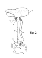
- FIG. 2 is a perspective view of the embodiment of FIG. 2 .
- FIG. 3 is an enlarged partial view of the embodiment of FIG. 2 .
- FIGS. 4 and 5 are perspective views of the embodiment of FIG. 2 with an attachment that is an extendable arm for holding objects.
- FIG. 6 is a perspective view of the embodiment of FIG. 2 with an attachment that is a baseplate with wheels on the bottom side.
- FIG. 7 is a perspective view of the opposite side of the embodiment of FIG. 6 .
- FIG. 8 is a perspective view of four shoe pieces associated with the embodiment of FIG. 2 .
- FIG. 9 is a perspective view of an attachment for the embodiment of FIG. 2 that holds an umbrella and an attachment that holds a water bottle.
- FIG. 10 is an enlarged partial view of the embodiment of FIG. 2 depicting seat, fastener system, and proximal end of pole.
- FIG. 11 is a diagram of a kit containing the present novel technology.
- FIG. 12 is a process flow describing one example method of using the present novel technology.
- FIGS. 1-12 illustrates a portable body support device or system 5 including a seat 10 or like support cushion, such as a bicycle seat or the like; a typically rectangular base plate 30 , and elongated member or pole 20 having a proximal end 21 and an oppositely disposed distal end 22 .
- the seat or cushion portion 10 typically may be attached to the proximal end 21 of the short elongated member or pole (typically about eighteen inches in length) 20 where the length of the elongated member 20 typically may be adjustable via a quick-release fastener system 15 .
- the opposite, distal end 22 typically may be attached to a typically rectangular base 30 .
- the base 30 typically has two front feet 35 and two oppositely disposed rear feet 36 extending therefrom.
- base 30 may have a plurality of feet 35 , 36 , rather than only two per side and/or four total.
- Each respective foot 35 , 36 typically has a cap 40 operationally connected thereto to increase traction with a given surface.
- the distal end 22 typically may not be centered relative to the base 30 , but may instead typically be offset such that the pole 20 intersects the base 30 closer to the front feet 35 than to the rear feet 36 .
- This base 30 may be firmly placed on a surface, such as the ground or floor, so that the user sits directly on the seat 10 with the base 30 underneath, typically with the user's feet likewise in ground contact.
- the system 5 may further be used as a chest support by placing two of the feet 35 , 36 against a wall and the opposing two feet 36 , 35 on the ground, or by simply placing two feet 35 , 36 on the ground, with the system 5 typically tilted toward the user. In this position, the user may engage their chest against the seat/cushion 10 and lean forward and extend his/her arms to an adjacent work area to complete tasks located close to ground level, such as carpentry finish work, electrician wiring tasks, and the like. This supportive positioning typically may help relieve stress on the lower back and knees that would normally be problematic for a user working on projects close to ground level.
- Both the cushioned seat 10 and the rectangular base 30 of the chair 5 typically may be easily detached from the pole 20 for convenient storage and mobility, and different seats or cushions 10 may be connected to the pole 20 for different uses, such as cushions 10 tailored for sitting and other cushions 10 configured to provide chest support. All components 10 , 20 , 30 may typically fit comfortably into the saddlebag of a motorcycle and/or similarly sized storage space, making the dual-purpose pole chairs 5 convenient for hunting, camping, travelling, working, and/or the like. Additionally, because its parts 10 , 20 , 30 typically may be detachable, the compact nature of the pole chair 5 may not substantially add to the clutter of a contractor's tool inventory.
- the chair 5 may typically include multiple attachments.
- One such attachment may be shoulder strap 45 that typically connects under the seat 10 and extends to attach to the rectangular base plate 30 , typically via a quick release fastener system 15 or the like. This typically may allow pole chair assembly 5 to be more easily transported.
- the quick-release fastener system 15 typically may provide a clamp or like apparatus 16 for engaging the seat 10 and other attachments to the elongated member 20 .
- the clamp 16 typically comprises a lever 17 that typically may be rotatably coupled to the (typically c-shaped) clamp 16 . As the lever 17 is rotated clockwise the total circumference of the c-clamp 16 typically may be decreased and the clamp 16 may tighten around the attachment 10 , 20 , 30 . Once the clamp 16 is substantially snug, the lever 17 may then be rotated so that it rests against c-clamp 16 , which also typically further tightens the clamp 16 .
- the arm assembly 50 typically includes a curved or circular cup holder member 52 attached to an elongated member 51 that may be connected to the chair 5 , typically just below the seat 10 of the chair 5 via quick-release fastener system 15 , such as by insertion of pin 54 into receptor 55 .
- holder member 52 may be substantially frustoconical in shape and/or size.
- the cup holder assembly 50 may be more typically connected via hinge 53 so that it may be pivoted down into an orientation parallel with the pole member 20 when not in use.
- Another attachment may be circular base member 60 having a set of connectors or prongs 61 for receiving each of the foot caps 40 on one side (typically the top side 62 ) and wheels or castors 65 on the opposite side (typically the bottom side 63 ).
- the base member 60 may be attached by engaging the feet caps 40 snuggly with the prongs 61 on the top side 62 of the base member 60 .
- This attachment 60 typically may allow the chair 5 to roll about when working on cars, motorcycles, carpentry tasks, and/or the like.
- Another attachment includes four shoe pieces 70 , each piece 70 respectively fitting onto each respective foot 35 , 36 of the chair 5 .
- On one side of each piece 70 typically may be a peg or like connector 71 matable with each foot cap 40 , similar to prongs 61 found on the top side of the circular base member 60 described above, and on the other side may be spike 72 .
- the chair 5 may be stuck or fastened firmly into grass, mud, sand, and/or like soft ground. This allows the chair 5 to be securely anchored to a great many surfaces.
- umbrella/umbrella holster 75 typically connected underneath seat/cushion 10 .
- umbrella holder 75 may connect to cushion 10 directly, seat 10 supports, via indirect attachment mechanisms (e.g., hook-and-loop material, adhesive, magnets, and/or the like).
- umbrella 75 may attach alternatively to fastener system 15 , pole 20 , base 30 , and/or the like.
- Another attachment includes water bottle attachment 80 , typically connected to the elongated pole 20 .
- the device consists of a sleeve 81 for holding the water bottle and two (typically elastic) straps 82 that attach the sleeve 81 to the pole 20 .
- water bottle attachment 80 may attach alternatively to seat 10 , fastener system 15 , base 30 , and/or the like.
- kits 85 e.g., as depicted in FIG. 11
- method 90 e.g., providing a support apparatus
- kit 85 may include, but is not limited to, seat 10 , quick-release fastener system 15 , clamp or like apparatus 16 , lever 17 , elongated member or pole 20 (typically having proximal end 21 and oppositely disposed distal end 22 ), typically rectangular base plate 30 , a plurality of front feet 35 (more typically two front feet 35 ), a plurality of oppositely disposed rear feet 36 (more typically two rear feet 36 ), caps 40 , shoulder straps 45 , arm assembly 50 (typically including elongated member 51 , cup holder member 52 , and hinge 53 ), circular base member 60 (typically having first, top side 62 and second, oppositely disposed bottom side 63 ), connectors/prongs 61 , shoe pieces 70 , pegs/anchors 71 , umbrella/umbrella holder 75 , and/or water bottle holder 80 (typically including sleeve 81 and straps 82 ).
- One non-limiting method 90 includes the steps of: providing a support apparatus 95 ; engaging a plurality of feet 100 ; engaging the cushion with a human chest 105 ; and manually engaging a work surface adjacent to the feet 110 .
- step 95 may provide but is not limited to a cushion portion 10 , that is typically configured to provide torso support; a rectangular base plate 30 having four feet 35 , 36 extending therefrom; a typically length-adjustable elongated pole 20 having a distal end 22 connected to the rectangular base portion 30 , and having an oppositely disposed proximal end 21 operationally connected to the cushion portion 10 , where the distal end 22 is uncentered relative to the rectangular base plate 30 ; and a fastener system 15 connected to the proximal end 21 and engaged with the seat 10 .
- step 110 may include but is not limited to an adjacent surface that is the ground 115 .
- One embodiment of step 100 may include but is not limited to engaging both feet 35 , 36 simultaneously with both the ground and a substantially vertical wall 120 .
- Another embodiment of step 100 may include but is not limited to engaging only two feet 35 , 36 with a surface 125 .
- a user may engage the front feet 35 with a ground surface or other like surface and the rear feet 36 with a wall or other like surface. The user may then lean or kneel down, and engage their chest with the seat portion 10 . The user may then extend their arms out to an adjacent work surface. It may first be necessary to adjust the length of the elongated pole 20 given variable distances to different work surfaces.
- the user may engage only the front feet 35 or the rear feet 36 with a surface.
- This embodiment allows the entire device to pivot about the point of contact between either set of feet 35 , 36 and the surface. This operation provides greater mobility for the user while still offering a stable, upper-body support.
- methods may include variances such as where the surface is the ground, where the feet engage both the ground and a wall simultaneously, where only two feet engage a surface, and/or the like. Further, method steps may be repeated, omitted, subcycled, altered, and/or the like for desired outcomes. Additionally, the above example method is but a nonexclusive example and in no way limits uses of the present novel technology.
Landscapes
- Chair Legs, Seat Parts, And Backrests (AREA)
- Special Chairs (AREA)
Abstract
A dual-purpose pole chair and torso support apparatus including a seat portion, a rectangular base plate having four feet, and an elongated pole extending from the seat portion having a proximal end and an oppositely disposed distal end. The seat portion is connected to the proximal end of the pole, while the rectangular base plate is connected to the distal end of the pole. Both the seat portion and the rectangular base plate are connected to the pole via a quick release fastener system.
Description
This application claims the benefit under 35 U.S.C. § 119(e) to U.S. Provisional Patent Application No. 62/361,177, filed on Jul. 27, 2016, which is incorporated herein by reference in its entirety.
The present novel technology relates generally to the furniture industry, and, more particularly, to a travel-friendly, dual-purpose pole chair.
The details of one or more embodiments of the subject matter described in this specification are set forth in the accompanying drawings and the description below. Other features, aspects, and advantages of the subject matter will become apparent from the description, the drawings, and the claims.
Both domestically and worldwide, mobile or portable seating has been an important addition to the world of sports, camping, construction, hunting, and the like. More specifically, in the fields of auto repair and construction, many stools and chairs have been developed to fit the need of working on tasks located at or below waist level; however, when projects become too close to ground level, these stools cease to be useful and offer no assistance to the workman.
Thus, there is a need for a stool or chair that can, in addition to functioning as a traditional chair or stool, both provide support and assistance for completing tasks at or around waist level as well as yielding upper body support when working near ground level.
The present novel technology addresses these needs.
Like reference numbers and designations in the various drawings indicate like elements.
For the purposes of promoting an understanding of the principles of the novel technology and presenting its currently understood best mode of operation, reference will now be made to the embodiments illustrated in the drawings and specific language will be used to describe the same. It will nevertheless be understood that no limitation of the scope of the novel technology is thereby intended, with such alterations and further modifications in the illustrated device and such further applications of the principles of the novel technology as illustrated therein being contemplated as would normally occur to one skilled in the art to which the novel technology relates.
The novel technology shown in FIGS. 1-12 illustrates a portable body support device or system 5 including a seat 10 or like support cushion, such as a bicycle seat or the like; a typically rectangular base plate 30, and elongated member or pole 20 having a proximal end 21 and an oppositely disposed distal end 22. The seat or cushion portion 10 typically may be attached to the proximal end 21 of the short elongated member or pole (typically about eighteen inches in length) 20 where the length of the elongated member 20 typically may be adjustable via a quick-release fastener system 15.
The opposite, distal end 22 typically may be attached to a typically rectangular base 30. The base 30 typically has two front feet 35 and two oppositely disposed rear feet 36 extending therefrom. In other implementations, base 30 may have a plurality of feet 35, 36, rather than only two per side and/or four total. Each respective foot 35, 36 typically has a cap 40 operationally connected thereto to increase traction with a given surface. The distal end 22 typically may not be centered relative to the base 30, but may instead typically be offset such that the pole 20 intersects the base 30 closer to the front feet 35 than to the rear feet 36. This base 30 may be firmly placed on a surface, such as the ground or floor, so that the user sits directly on the seat 10 with the base 30 underneath, typically with the user's feet likewise in ground contact.
The system 5 may further be used as a chest support by placing two of the feet 35, 36 against a wall and the opposing two feet 36, 35 on the ground, or by simply placing two feet 35, 36 on the ground, with the system 5 typically tilted toward the user. In this position, the user may engage their chest against the seat/cushion 10 and lean forward and extend his/her arms to an adjacent work area to complete tasks located close to ground level, such as carpentry finish work, electrician wiring tasks, and the like. This supportive positioning typically may help relieve stress on the lower back and knees that would normally be problematic for a user working on projects close to ground level.
Both the cushioned seat 10 and the rectangular base 30 of the chair 5 typically may be easily detached from the pole 20 for convenient storage and mobility, and different seats or cushions 10 may be connected to the pole 20 for different uses, such as cushions 10 tailored for sitting and other cushions 10 configured to provide chest support. All components 10, 20, 30 may typically fit comfortably into the saddlebag of a motorcycle and/or similarly sized storage space, making the dual-purpose pole chairs 5 convenient for hunting, camping, travelling, working, and/or the like. Additionally, because its parts 10, 20, 30 typically may be detachable, the compact nature of the pole chair 5 may not substantially add to the clutter of a contractor's tool inventory.
In some embodiments, the chair 5 may typically include multiple attachments. One such attachment may be shoulder strap 45 that typically connects under the seat 10 and extends to attach to the rectangular base plate 30, typically via a quick release fastener system 15 or the like. This typically may allow pole chair assembly 5 to be more easily transported.
The quick-release fastener system 15 typically may provide a clamp or like apparatus 16 for engaging the seat 10 and other attachments to the elongated member 20. The clamp 16 typically comprises a lever 17 that typically may be rotatably coupled to the (typically c-shaped) clamp 16. As the lever 17 is rotated clockwise the total circumference of the c-clamp 16 typically may be decreased and the clamp 16 may tighten around the attachment 10, 20, 30. Once the clamp 16 is substantially snug, the lever 17 may then be rotated so that it rests against c-clamp 16, which also typically further tightens the clamp 16.
Another attachment is an extendable arm assembly 50 for holding cups, beverages, and the like. The arm assembly 50 typically includes a curved or circular cup holder member 52 attached to an elongated member 51 that may be connected to the chair 5, typically just below the seat 10 of the chair 5 via quick-release fastener system 15, such as by insertion of pin 54 into receptor 55. In some implementations, holder member 52 may be substantially frustoconical in shape and/or size. The cup holder assembly 50 may be more typically connected via hinge 53 so that it may be pivoted down into an orientation parallel with the pole member 20 when not in use.
Another attachment may be circular base member 60 having a set of connectors or prongs 61 for receiving each of the foot caps 40 on one side (typically the top side 62) and wheels or castors 65 on the opposite side (typically the bottom side 63). The base member 60 may be attached by engaging the feet caps 40 snuggly with the prongs 61 on the top side 62 of the base member 60. This attachment 60 typically may allow the chair 5 to roll about when working on cars, motorcycles, carpentry tasks, and/or the like.
Another attachment includes four shoe pieces 70, each piece 70 respectively fitting onto each respective foot 35, 36 of the chair 5. On one side of each piece 70 typically may be a peg or like connector 71 matable with each foot cap 40, similar to prongs 61 found on the top side of the circular base member 60 described above, and on the other side may be spike 72. When these pieces 70 are attached to the respective feet caps 40, the chair 5 may be stuck or fastened firmly into grass, mud, sand, and/or like soft ground. This allows the chair 5 to be securely anchored to a great many surfaces.
Another attachment includes umbrella/umbrella holster 75, typically connected underneath seat/cushion 10. For example, umbrella holder 75 may connect to cushion 10 directly, seat 10 supports, via indirect attachment mechanisms (e.g., hook-and-loop material, adhesive, magnets, and/or the like). In other implementations, umbrella 75 may attach alternatively to fastener system 15, pole 20, base 30, and/or the like.
Another attachment includes water bottle attachment 80, typically connected to the elongated pole 20. The device consists of a sleeve 81 for holding the water bottle and two (typically elastic) straps 82 that attach the sleeve 81 to the pole 20. In other implementations, water bottle attachment 80 may attach alternatively to seat 10, fastener system 15, base 30, and/or the like.
Other embodiments and/or implementations of the present novel technology may be a kit 85 (e.g., as depicted in FIG. 11 ) and/or as a method 90 (e.g., providing a support apparatus).
One embodiment of a kit 85 may include, but is not limited to, seat 10, quick-release fastener system 15, clamp or like apparatus 16, lever 17, elongated member or pole 20 (typically having proximal end 21 and oppositely disposed distal end 22), typically rectangular base plate 30, a plurality of front feet 35 (more typically two front feet 35), a plurality of oppositely disposed rear feet 36 (more typically two rear feet 36), caps 40, shoulder straps 45, arm assembly 50 (typically including elongated member 51, cup holder member 52, and hinge 53), circular base member 60 (typically having first, top side 62 and second, oppositely disposed bottom side 63), connectors/prongs 61, shoe pieces 70, pegs/anchors 71, umbrella/umbrella holder 75, and/or water bottle holder 80 (typically including sleeve 81 and straps 82).
One non-limiting method 90 includes the steps of: providing a support apparatus 95; engaging a plurality of feet 100; engaging the cushion with a human chest 105; and manually engaging a work surface adjacent to the feet 110. Typically step 95 may provide but is not limited to a cushion portion 10, that is typically configured to provide torso support; a rectangular base plate 30 having four feet 35, 36 extending therefrom; a typically length-adjustable elongated pole 20 having a distal end 22 connected to the rectangular base portion 30, and having an oppositely disposed proximal end 21 operationally connected to the cushion portion 10, where the distal end 22 is uncentered relative to the rectangular base plate 30; and a fastener system 15 connected to the proximal end 21 and engaged with the seat 10.
One embodiment of step 110 may include but is not limited to an adjacent surface that is the ground 115. One embodiment of step 100 may include but is not limited to engaging both feet 35, 36 simultaneously with both the ground and a substantially vertical wall 120. Another embodiment of step 100 may include but is not limited to engaging only two feet 35, 36 with a surface 125.
In operation, a user may engage the front feet 35 with a ground surface or other like surface and the rear feet 36 with a wall or other like surface. The user may then lean or kneel down, and engage their chest with the seat portion 10. The user may then extend their arms out to an adjacent work surface. It may first be necessary to adjust the length of the elongated pole 20 given variable distances to different work surfaces.
In another embodiment, the user may engage only the front feet 35 or the rear feet 36 with a surface. This embodiment allows the entire device to pivot about the point of contact between either set of feet 35, 36 and the surface. This operation provides greater mobility for the user while still offering a stable, upper-body support.
Further implementations of methods may include variances such as where the surface is the ground, where the feet engage both the ground and a wall simultaneously, where only two feet engage a surface, and/or the like. Further, method steps may be repeated, omitted, subcycled, altered, and/or the like for desired outcomes. Additionally, the above example method is but a nonexclusive example and in no way limits uses of the present novel technology.
While the invention has been illustrated and described in detail in the drawings and foregoing description, the same is to be considered as illustrative and not restrictive in character. It is understood that the embodiments have been shown and described in the foregoing specification in satisfaction of the best mode and enablement requirements. It is understood that one of ordinary skill in the art could readily make a nigh-infinite number of insubstantial changes and modifications to the above-described embodiments and that it would be impractical to attempt to describe all such embodiment variations in the present specification. Accordingly, it is understood that all changes and modifications that come within the spirit of the invention are desired to be protected.
Claims (4)
1. A dual purpose chair and torso support apparatus, comprising:
a seat portion;
a fastener system operationally connected to the seat portion;
an elongated pole extending from the seat portion and having a proximal end connected to the seat portion via the fastener system and an oppositely disposed distal end; and
a rectangular base plate operationally connected to the distal end and having four feet extending therefrom;
wherein the seat portion is configured to provide torso support;
wherein the pole is length-adjustable; and
wherein the distal end of the pole is not centered relative to the rectangular base plate; and
a circular base member having a first, top side; a second, bottom, oppositely disposed side; and four prongs attached to the first side of the circular base member and extending therefrom configured to engage the four feet.
2. The device of claim 1 wherein the circular base member further comprises a plurality of wheels operationally connected to the second side of the circular base member.
3. A dual purpose chair and torso support apparatus, comprising:
a seat portion;
a fastener system operationally connected to the seat portion;
an elongated pole extending from the seat portion and having a proximal end connected to the seat portion via the fastener system and an oppositely disposed distal end; and
a rectangular base plate operationally connected to the distal end and having four feet extending therefrom;
wherein the seat portion is configured to provide torso support;
wherein the pole is length-adjustable; and
wherein the distal end of the pole is not centered relative to the rectangular base plate; and
a plurality of spiked shoe pieces, each respective shoe piece attached to a respective foot.
4. A kit for a dual purpose chair and torso support apparatus, comprising:
an elongated pole having a proximal end and an oppositely disposed distal end;
a seat portion connectable to the proximal end of the pole;
a base plate having a plurality of feet extending therefrom and connectable to the distal end of the pole; and
a quick-release fastener system connectable between the pole and to the seat portion; the kit further comprising a plurality of spiked shoe pieces, each respective spike shoe piece connectable to a respective foot.
Priority Applications (1)
| Application Number | Priority Date | Filing Date | Title |
|---|---|---|---|
| US15/346,800 US10016062B2 (en) | 2016-07-12 | 2016-11-09 | Dual-purpose pole chair |
Applications Claiming Priority (2)
| Application Number | Priority Date | Filing Date | Title |
|---|---|---|---|
| US201662361177P | 2016-07-12 | 2016-07-12 | |
| US15/346,800 US10016062B2 (en) | 2016-07-12 | 2016-11-09 | Dual-purpose pole chair |
Publications (2)
| Publication Number | Publication Date |
|---|---|
| US20180014653A1 US20180014653A1 (en) | 2018-01-18 |
| US10016062B2 true US10016062B2 (en) | 2018-07-10 |
Family
ID=60942263
Family Applications (1)
| Application Number | Title | Priority Date | Filing Date |
|---|---|---|---|
| US15/346,800 Active 2036-12-10 US10016062B2 (en) | 2016-07-12 | 2016-11-09 | Dual-purpose pole chair |
Country Status (1)
| Country | Link |
|---|---|
| US (1) | US10016062B2 (en) |
Cited By (1)
| Publication number | Priority date | Publication date | Assignee | Title |
|---|---|---|---|---|
| US11197551B2 (en) * | 2019-11-08 | 2021-12-14 | The Boeing Company | Seat transit systems and methods |
Families Citing this family (4)
| Publication number | Priority date | Publication date | Assignee | Title |
|---|---|---|---|---|
| US9968195B2 (en) * | 2015-10-20 | 2018-05-15 | Ergo Impact, LLC | Adjustable seat and leaning apparatus |
| US10932572B1 (en) | 2019-05-28 | 2021-03-02 | Veronica Leggette | Height-adjusting stool |
| US11344129B2 (en) * | 2020-01-23 | 2022-05-31 | Lawrence Walker | Portable seat assembly |
| WO2022236117A1 (en) * | 2021-05-07 | 2022-11-10 | Jason Hammond | Stool with instrument and/or accessory storage |
Citations (18)
| Publication number | Priority date | Publication date | Assignee | Title |
|---|---|---|---|---|
| US3542326A (en) * | 1968-08-21 | 1970-11-24 | Alfred G Reapsummer | Adjustable chair slide mechanism |
| US4657218A (en) * | 1986-01-21 | 1987-04-14 | J. I. Case Company | Adjustable chair pedestal |
| US4673155A (en) * | 1986-04-18 | 1987-06-16 | Binder William T | Vertically adjustable boat furniture |
| DE9200169U1 (en) | 1992-01-09 | 1992-03-19 | Rau, Siegfried, 7323 Hattenhofen | Standing relief |
| US5238013A (en) | 1991-08-15 | 1993-08-24 | Tubular Fabricators Industry, Inc. | Walking aid cane |
| US5673966A (en) * | 1996-10-07 | 1997-10-07 | William D. Morton, Jr. | Duck hunter's tule seat |
| US6893097B1 (en) * | 2003-07-07 | 2005-05-17 | Alan H. Ebensperger | Outdoor stool system |
| US20060082203A1 (en) * | 2004-10-20 | 2006-04-20 | Gasser Chair Company, Inc. | Adjustable gaming stool with releasable locking assembly |
| US7070241B2 (en) * | 2004-04-08 | 2006-07-04 | Caroline Saulnier | Ergonomic seating assembly |
| US20070236053A1 (en) | 2006-03-28 | 2007-10-11 | West Steven D | Tool for providing support to the human upper body when having to lean over to work |
| US20110121619A1 (en) * | 2008-07-28 | 2011-05-26 | The Coleman Company, Inc. | Stemmed glass holder |
| US20110316313A1 (en) * | 2010-06-25 | 2011-12-29 | Gasser Chair Company, Inc. | Furniture base with central collector |
| US20120086252A1 (en) * | 2011-12-14 | 2012-04-12 | Simon Hong | Sit-Stand Chair |
| US8459736B1 (en) * | 2010-09-14 | 2013-06-11 | Floyd A. Begley, Jr. | Poolside chair and associated use thereof |
| US20150289494A1 (en) * | 2014-04-09 | 2015-10-15 | Chris J. Davis | Pedestal Mountable Bait Holding Device |
| US20170042334A1 (en) * | 2014-05-23 | 2017-02-16 | Hans Christian Mengshoel | Activating platform |
| US20170105530A1 (en) * | 2015-10-20 | 2017-04-20 | Ergo Impact, LLC | Adjustable seat and leaning apparatus |
| US20170296003A1 (en) * | 2016-04-18 | 2017-10-19 | Andrew Hoesman | Bathing Assistance Assembly |
-
2016
- 2016-11-09 US US15/346,800 patent/US10016062B2/en active Active
Patent Citations (18)
| Publication number | Priority date | Publication date | Assignee | Title |
|---|---|---|---|---|
| US3542326A (en) * | 1968-08-21 | 1970-11-24 | Alfred G Reapsummer | Adjustable chair slide mechanism |
| US4657218A (en) * | 1986-01-21 | 1987-04-14 | J. I. Case Company | Adjustable chair pedestal |
| US4673155A (en) * | 1986-04-18 | 1987-06-16 | Binder William T | Vertically adjustable boat furniture |
| US5238013A (en) | 1991-08-15 | 1993-08-24 | Tubular Fabricators Industry, Inc. | Walking aid cane |
| DE9200169U1 (en) | 1992-01-09 | 1992-03-19 | Rau, Siegfried, 7323 Hattenhofen | Standing relief |
| US5673966A (en) * | 1996-10-07 | 1997-10-07 | William D. Morton, Jr. | Duck hunter's tule seat |
| US6893097B1 (en) * | 2003-07-07 | 2005-05-17 | Alan H. Ebensperger | Outdoor stool system |
| US7070241B2 (en) * | 2004-04-08 | 2006-07-04 | Caroline Saulnier | Ergonomic seating assembly |
| US20060082203A1 (en) * | 2004-10-20 | 2006-04-20 | Gasser Chair Company, Inc. | Adjustable gaming stool with releasable locking assembly |
| US20070236053A1 (en) | 2006-03-28 | 2007-10-11 | West Steven D | Tool for providing support to the human upper body when having to lean over to work |
| US20110121619A1 (en) * | 2008-07-28 | 2011-05-26 | The Coleman Company, Inc. | Stemmed glass holder |
| US20110316313A1 (en) * | 2010-06-25 | 2011-12-29 | Gasser Chair Company, Inc. | Furniture base with central collector |
| US8459736B1 (en) * | 2010-09-14 | 2013-06-11 | Floyd A. Begley, Jr. | Poolside chair and associated use thereof |
| US20120086252A1 (en) * | 2011-12-14 | 2012-04-12 | Simon Hong | Sit-Stand Chair |
| US20150289494A1 (en) * | 2014-04-09 | 2015-10-15 | Chris J. Davis | Pedestal Mountable Bait Holding Device |
| US20170042334A1 (en) * | 2014-05-23 | 2017-02-16 | Hans Christian Mengshoel | Activating platform |
| US20170105530A1 (en) * | 2015-10-20 | 2017-04-20 | Ergo Impact, LLC | Adjustable seat and leaning apparatus |
| US20170296003A1 (en) * | 2016-04-18 | 2017-10-19 | Andrew Hoesman | Bathing Assistance Assembly |
Non-Patent Citations (1)
| Title |
|---|
| Offhand Technique Reference Material, the Fuzzy Limey, www.rimfirecentral.com. |
Cited By (1)
| Publication number | Priority date | Publication date | Assignee | Title |
|---|---|---|---|---|
| US11197551B2 (en) * | 2019-11-08 | 2021-12-14 | The Boeing Company | Seat transit systems and methods |
Also Published As
| Publication number | Publication date |
|---|---|
| US20180014653A1 (en) | 2018-01-18 |
Similar Documents
| Publication | Publication Date | Title |
|---|---|---|
| US10016062B2 (en) | Dual-purpose pole chair | |
| US7393057B2 (en) | Portable adjustable headrest | |
| US8146615B1 (en) | Crutch device with leg support | |
| JP6970179B2 (en) | Chair with exercise means | |
| US9289347B2 (en) | Erect posture mobility device with low turn radius | |
| US6467843B1 (en) | Collapsible seat | |
| US10624810B2 (en) | Hands-free crutch | |
| US3477673A (en) | Leaning device to reduce fatigue | |
| US8403408B2 (en) | Personal support device | |
| US4676547A (en) | Portable spectator's stool | |
| US9301618B2 (en) | Exercise device, connector and methods of use thereof | |
| US4647066A (en) | Orthopedic chair | |
| US7648447B2 (en) | Leg exercise device for use with an office chair | |
| US10272289B2 (en) | Lower extremity receiving device for providing enhanced leg mobility during lower body exercise | |
| US9808393B2 (en) | Mobility aids and related methods | |
| US9345297B2 (en) | Walker standing assist device | |
| US20040094668A1 (en) | Aircraft seat footrest system and method | |
| US7624737B2 (en) | Anterior support device | |
| US20070182233A1 (en) | Neck chair with arm rests | |
| US6565053B1 (en) | Cane holder | |
| US9480341B2 (en) | Physical support device | |
| US20060055128A1 (en) | Multi style golf cart towing device | |
| US20130125794A1 (en) | Standing Support Apparatus | |
| US6033016A (en) | Seat | |
| US20200407994A1 (en) | Adjustable seat device for a swimming pool |
Legal Events
| Date | Code | Title | Description |
|---|---|---|---|
| STCF | Information on status: patent grant |
Free format text: PATENTED CASE |
|
| MAFP | Maintenance fee payment |
Free format text: PAYMENT OF MAINTENANCE FEE, 4TH YEAR, MICRO ENTITY (ORIGINAL EVENT CODE: M3551); ENTITY STATUS OF PATENT OWNER: MICROENTITY Year of fee payment: 4 |