US10015855B2 - Dithering and dimming techniques for light emitting diode (LED) lighting systems - Google Patents
Dithering and dimming techniques for light emitting diode (LED) lighting systems Download PDFInfo
- Publication number
- US10015855B2 US10015855B2 US15/383,402 US201615383402A US10015855B2 US 10015855 B2 US10015855 B2 US 10015855B2 US 201615383402 A US201615383402 A US 201615383402A US 10015855 B2 US10015855 B2 US 10015855B2
- Authority
- US
- United States
- Prior art keywords
- dimming
- level
- color
- range
- current source
- Prior art date
- Legal status (The legal status is an assumption and is not a legal conclusion. Google has not performed a legal analysis and makes no representation as to the accuracy of the status listed.)
- Active
Links
Images


Classifications
-
- H05B33/0845—
-
- H—ELECTRICITY
- H05—ELECTRIC TECHNIQUES NOT OTHERWISE PROVIDED FOR
- H05B—ELECTRIC HEATING; ELECTRIC LIGHT SOURCES NOT OTHERWISE PROVIDED FOR; CIRCUIT ARRANGEMENTS FOR ELECTRIC LIGHT SOURCES, IN GENERAL
- H05B45/00—Circuit arrangements for operating light-emitting diodes [LED]
- H05B45/10—Controlling the intensity of the light
-
- H05B33/0815—
-
- H05B33/0818—
-
- H—ELECTRICITY
- H05—ELECTRIC TECHNIQUES NOT OTHERWISE PROVIDED FOR
- H05B—ELECTRIC HEATING; ELECTRIC LIGHT SOURCES NOT OTHERWISE PROVIDED FOR; CIRCUIT ARRANGEMENTS FOR ELECTRIC LIGHT SOURCES, IN GENERAL
- H05B45/00—Circuit arrangements for operating light-emitting diodes [LED]
- H05B45/30—Driver circuits
- H05B45/32—Pulse-control circuits
- H05B45/327—Burst dimming
-
- H—ELECTRICITY
- H05—ELECTRIC TECHNIQUES NOT OTHERWISE PROVIDED FOR
- H05B—ELECTRIC HEATING; ELECTRIC LIGHT SOURCES NOT OTHERWISE PROVIDED FOR; CIRCUIT ARRANGEMENTS FOR ELECTRIC LIGHT SOURCES, IN GENERAL
- H05B45/00—Circuit arrangements for operating light-emitting diodes [LED]
- H05B45/30—Driver circuits
- H05B45/37—Converter circuits
- H05B45/3725—Switched mode power supply [SMPS]
- H05B45/375—Switched mode power supply [SMPS] using buck topology
Definitions
- Various embodiments concern firmware modification and, more specifically, techniques for modifying power signals for LED-based lighting systems.
- LEDs light emitting diodes
- LED-based systems are capable of having longer lives and offering high energy efficiency, several issues still exist including the degradation of color over time and the responsiveness of color tuning adjustments. These issues can be compounded when multiple LED-based lighting systems are placed near one another or are coupled directly to one another.
- PCBAs printed circuit board assemblies
- LEDs often exhibit undesirable acoustic effects when the PCBAs are driven at particular (e.g., resonant) frequencies in the human hearing range (e.g., approximately 50 Hz to 25 kHz).
- resonant frequencies e.g., approximately 50 Hz to 25 kHz.
- sound may be produced by vibrating capacitors, such as piezoelectric ceramic capacitors that change dimensions in response to an applied voltage.
- Some inductors may also create noise by magnetostriction.
- a light source can be characterized by its color temperature and by its color rendering index (CRI).
- the color temperature of a light source is the temperature at which the color of light emitted from a heated black body radiator is matched by the color of the light source.
- the correlated color temperature (CCT) of the light source is the temperature at which the color of light emitted from a heated black body radiator is approximated by the color of the light source.
- the CCT can also be used to represent chromaticity of white light sources. But because chromaticity is two-dimensional, Duv (as defined in ANSI C78.377) can be used to provide another dimension. When used with a MacAdam ellipse (which represents the colors distinguishable to the human eye), the CCT and Duv allow the visible color output by an LED-based lighting system to be more precisely controlled (e.g., by being tuned).
- the CRI is a rating system that measures the accuracy of how well a light source reproduces the color of an illuminated object in comparison to an ideal or natural light source.
- the CRI is determined based on an average of eight different colors (R1-R8).
- a ninth color (R9) is a fully saturated test color that is not used in calculating CRI, but can be used to more accurately mix and reproduce the other colors.
- the CCT and CRI of LEDs is typically difficult to tune and adjust. Further difficulty arises when trying to maintain an acceptable CRI while varying the CCT of an LED.
- FIG. 1A depicts an example of an LED-based lighting system that includes an LED board coupled to a logic module by a ribbon cable as may occur in various embodiments.
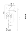
- FIG. 1B depicts an example circuit that is able to facilitate the dimming process described herein.
- FIG. 1C depicts another example circuit that is able to facilitate the dimming process described herein.
- FIG. 1D depicts another example circuit that is able to facilitate the dimming process described herein.
- FIG. 1E depicts another example circuit that is able to facilitate the dimming process described herein.
- FIG. 1F depicts another example circuit that is able to facilitate the dimming process described herein.
- FIG. 1G depicts another example circuit that is able to facilitate the dimming process described herein.
- FIG. 2 depicts four-stage process for dimming LEDs to extinction.
- FIG. 3A depicts a first stage of a process for modifying the current supplied to one or more LEDs, thereby decreasing brightness.
- FIG. 3B depicts a second stage of the process.
- FIG. 3C depicts a third stage of the process.
- FIG. 3D depicts a fourth stage of the process.
- FIG. 4 depicts a process for substantially eliminating the acoustic effects of PWM using software or firmware.
- FIG. 5 is a block diagram illustrating an example of a computer system in which at least some operations described herein can be implemented.
- FIG. 6A is a high-level block diagram of an LED-based lighting system that includes a logic module connected to one or more LED boards.
- FIG. 6B is another high-level block diagram of an LED-based lighting system that includes a logic module connected to one or more LED boards
- FIG. 7 depicts a process for controllably tuning one or more LED boards using a logic module.
- various embodiments are described herein that relate to techniques for dimming LEDs. More specifically, various embodiments relate to systems and methods for selectively providing current to power LED boards, fixtures, etc., that allow the brightness level of the LEDs to be more precisely controlled.
- the techniques introduced here enable the LEDs to be smoothly dimmed from maximum brightness down to “actual extinction” (e.g., where an individual is not able to see any light despite looking straight at the LED) or “pseudo-extinction” (e.g., where the individual is not able to any light reflected off of most materials).
- the techniques may allow brightness to be dimmed from 100% down to 0.00001% brightness (and, in some instances, even lower).
- the reduction in maximum luminous flux may be from 100 million to 1, while for pseudo-extinction the reduction in maximum luminous flux may be from 10 million to 1.
- the systems and techniques described herein allow a user to dim LEDs to extinction without any significant gaps in the available levels of brightness (i.e., a noticeable drop rather than a smooth transition between brightness levels).
- pulse width modulation (PWM) and shunting techniques may be used to control the power provided to each color channel of an LED board.
- the power (and brightness) can be more precisely controlled by simultaneously modifying the PWM and the duty cycle of the circuit(s) involved.
- PWM signals also generally cause LEDs to produce an undesirable acoustic effect (e.g., by vibrating the capacitors on the PCBA).
- the cumulative acoustic effect can become white noise.
- dithering is not necessary when the frequency falls below 25 kHz because the amplitude of the input current is so small the resulting acoustic effects are negligible.
- inventions introduced herein can be embodied as special-purpose hardware (e.g., circuitry), as programmable circuitry appropriately programmed with software and/or firmware, or as a combination of special-purpose and programmable circuitry.
- embodiments may include a machine-readable medium having stored thereon instructions which may be used to program a computer (or another electronic device) to perform a process.
- the machine-readable medium may include, but is not limited to, floppy diskettes, optical disks, compact disk read-only memories (CD-ROMs), magneto-optical disks, read-only memories (ROMs), random access memories (RAMs), erasable programmable read-only memories (EPROMs), electrically erasable programmable read-only memories (EEPROMs), magnetic or optical cards, flash memory, or any other type of media/machine-readable medium suitable for storing electronic instructions.
- CD-ROMs compact disk read-only memories
- ROMs read-only memories
- RAMs random access memories
- EPROMs erasable programmable read-only memories
- EEPROMs electrically erasable programmable read-only memories
- references in this specification to “one embodiment” or “an embodiment” means that a particular feature, structure, or characteristic described in connection with the embodiment is included in at least one embodiment of the disclosure.
- the appearances of the phrase “in one embodiment” or “in some embodiments” in various places in the specification are not necessarily all referring to the same embodiment(s), nor are separate or alternative embodiments mutually exclusive of other embodiments.
- various features are described which may be exhibited by some embodiments and not by others.
- various requirements are described which may be requirements for some embodiments but not other embodiments.
- the words “comprise,” “comprising,” and the like are to be construed in an inclusive sense, as opposed to an exclusive or exhaustive sense; that is to say, in the sense of “including, but not limited to.”
- the terms “connected,” “coupled,” or any variant thereof means any connection or coupling, either direct or indirect, between two or more elements; the coupling or connection between the elements can be physical, logical, or a combination thereof.
- two devices may be coupled directly, or via one or more intermediary channels or devices.
- devices may be coupled in such a way that information can be passed there between, while not sharing any physical connection with one another.
- module refers broadly to software, hardware, or firmware (or any combination thereof) components. Modules are typically functional components that can generate useful data or other output using specified input(s). A module may or may not be self-contained.
- FIG. 1A depicts an example of an LED-based lighting system 100 that includes an LED-based light source, such as an LED board 102 , coupled to a logic module 104 (which may also be referred to as a color tuning module) by a ribbon cable 106 .
- an LED-based light source such as an LED board 102
- a logic module 104 which may also be referred to as a color tuning module
- the LED board 102 is illustrated by FIG. 1A as an array of LEDs 108 positioned linearly on a substrate, other arrangements are also possible and, in some cases, may be preferable.
- the LED board 102 may include a circular arrangement or cluster of mid-power LEDs, a single high power LED, or some other lighting feature.
- FIGS. 1B-G depict various example circuits that are able to facilitate the dimming process described herein.
- FIG. 1B depicts an integrated “mixer” circuit that can be used to controllably provide current to the LED(s), while FIG. 1C depicts a “fast shunt” that can divert current and thereby decrease input current.
- FIG. 1D depicts a “fast pulse” circuit that can be used to quickly provide small amounts of input current with minimal rise time.
- FIG. 1E provides a high-level overview of the circuit assembly as a whole, which is able to perform the dimming techniques described herein.
- dimming function i.e., are “dimmable” that allows a user to selectively control how much light a particular light source produces.
- dimming the light source the user is able to modify the brightness of the light source. More specifically, the dimming process described here allows the LEDs to be smoothly dimmed from maximum brightness down to “actual extinction” (e.g., where an individual is not able to see any light despite looking straight at the LED) or “pseudo-extinction” (e.g., where the individual is not able to any light reflected off of most materials). Smooth transitions between the different brightness levels generally require that each color channel of an LED board have minimal error (e.g., within a couple percent).
- LEDs can be rapidly switched on and off, dimming has traditionally been accomplished using PWM. More specifically, the apparent intensity/brightness of an LED could be dimmed by adjusting the relative duration of each pulse of current supplied to the LED and the time between pulses. However, these pulses must occur with a high enough frequency that the LED appears to be continuously lit, otherwise flickering will result. Because of this limitation and others, once the user reaches a predetermined brightness threshold, the LEDs of conventional lighting systems shut off entirely. Said another way, once the brightness level reaches a predetermined lower threshold, the LEDs shut off entirely, which is easily noticeable by a user.
- a compromise must be made between frame rate (i.e., corresponds to the frequency, or the inverse of the time period over which a pulse, or series of pulses, repeats itself), resolution (i.e., the maximum number of pulses that are able to fit into a period; generally measured in bits), and flicker.
- frame rate i.e., corresponds to the frequency, or the inverse of the time period over which a pulse, or series of pulses, repeats itself
- resolution i.e., the maximum number of pulses that are able to fit into a period; generally measured in bits
- flicker i.e., the maximum number of pulses that are able to fit into a period; generally measured in bits
- PWM resolution typically decreases.
- certain frequencies e.g., 1 kHz
- the process as shown in FIG. 2 , can be used to separately or simultaneously dim the color channels of an LED board.
- the dimming range of stage one typically extends from 100% (i.e., full brightness) to approximately 20%.
- the dimming range of stage two typically extends from 20% to approximately 0.3%.
- the dimming range of stage three typically extends from 0.3% to approximately 0.00001%.
- Stage four meanwhile, is able to provide an additional 500:1 reduction in brightness.
- the numbers listed here refer to the approximately percentage of full brightness that is governed by each stage. One skilled in the art will recognize these numbers are approximations and that modifications to the dimming techniques described here, such as using different circuits, may affect the cutoffs and ranges of each stage.
- stage one utilizes an integrated circuit that is able to provide a consistent (i.e., controlled) level of current in response to receiving an input voltage between 0.5V and 2.5V.
- the input voltage is generated (e.g., by a logic module) using PWM and a duty cycle in combination with an RC circuit that allows the input signal to be easily converted from digital to analog.
- the integrated circuit is configured to produce a maximum current (i.e., LED at 100% brightness) at 20 kHz when the input voltage exceeds 2.5V and a minimum current (i.e., LED at 20% brightness) at 1 MHz when the input voltage is 0.5V.
- a maximum current i.e., LED at 100% brightness
- a minimum current i.e., LED at 20% brightness
- the integrated circuit is able to generate a regulated current that is linearly based on the input voltage. That is, an input voltage between 0.5V and 2.5V allows the integrated circuit to produce an intermediate level of current that is based on the input voltage.
- the integrated circuit can also be readily turned on and off (e.g., using a transistor-transistor logic (TTL)). As illustrated in FIG. 3A , the integrated circuit is able to substantially maintain the current at or near the appropriate level (e.g., using resistors).
- TTL transistor-transistor logic
- stage two utilizes a second circuit (a “fast shunt”) that modulates the effects of the integrated circuit described above by selectively shunting the current provided by the integrated circuit (as described above). Dimming within stage two requires several steps be performed. First, an input voltage of 0.5V is provided to the integrated circuit, which causes the brightness level to remain steady at 20%. Second, the fast shunt is turned off and on at various frequencies to achieve a desired brightness level.
- FIG. 3B illustrates a scenario where a fixed frame width experiences less current as the duty cycle of the fast shunt decreases. But the fast shunt still experiences a lower limit as to how much the frame width can be decreased before flickering occurs.
- This lower limit is influenced by various factors, including the rise time of the input current produced by the integrated circuit and fast shunt and/or digital control limits of the FPGA.
- Stages one and two typically utilize a buck converter (i.e., a voltage step down and current step up converter) as the current driver, while stages three and four utilize an analog driver.
- Buck converters e.g., AL 8806
- AL 8806 a voltage step down and current step up converter
- one or more analog drivers are preferably used as the input current decreases (i.e., as responsiveness and rise time become increasingly important).
- stage three utilizes a third circuit (“micro pulse circuit”) that uses PWM to produce a small current (e.g., 10 milliamps).
- the micro pulse circuit generally takes about 10 nanoseconds to turn on and off, which allows the output current to be controlled at a high resolution.
- stage three neither the integrated circuit nor the fast shunt are used to generate the output current. As such, a “handoff” must occur between the integrated circuit and fast shunt in stage two and the micro pulse circuit in stage three.
- a substantially seamless (i.e., unnoticeable) handoff between the two stages requires that the brightness level generated by the micro pulse circuit at maximum current and maximum duty cycle substantially matches the brightness level generated by the integrated circuit and fast shunt at minimum current and minimum duty cycle.
- the pulses provided by both the fast shunt and the micro pulse circuit remain 25 kHz, which is out of acoustic range and typically does not experience problems with flickering.
- the duty cycle of the micro pulse circuit is decreased until the minimum brightness is reached before the LED would appear to turn off (e.g., a 10 milliamp pulse every 40 microseconds).
- stage four stretches out the frame width of the minimum current supplied by the micro pulse circuit. That is, the minimum current is supplied less frequently (e.g., a 10 milliamp pulse is supplied every 60, 80, or 100 microseconds). Stretching of the frame width causes the frequency of the signal to incrementally decrease. For example, some embodiments may be configured to decrease the frequency of the pulses of current from 25 kHz to 50 Hz.
- Stages two, three, and four could be completed as many times as necessary to meet certain “dim to extinction” objectives.
- stages two, three, and four may be logically replicated to decrease the brightness even further than the lowest level made possible by stage four.
- certain compromises may need to be made (e.g., with respect to flickering and acoustics).
- the dimming stages described above could also be delayed by a certain period of time. For example, a user may elect to turn an LED-based light source off entirely, and a logic module could delay decreasing the brightness. As another example, a user might simply elect a brightness level, and the logic module may decrease or increase the brightness over time to reach the specified brightness level.
- a buck converter (e.g., AL 8806) has a single control input to provide both digital PWM and analog dimming; however, a mixer is required to provide both functions (as shown in FIG. 1F ).
- the analog command is created at point A by a PWM signal from the microprocessor.
- the PWM signal is smoothed by the low pass filter composed of R 1 , R 2 , R 3 , C 1 , C 2 , C 3 , and the operational amplifier (“op amp”).
- op amp operational amplifier
- a voltage varying from 0.5 V to 2.5 V controls the buck converter output current, which typically ranges from 0.2 A to 1.0 A. This current range is used to achieve the first 5 to 1 dimming range.
- the fast shunt gives much better control than the PWM built into the buck converter.
- the reason for this is that the buck converter, when used to perform PWM, turns off its switching FET. While this is effective for turning off the LED current during the “on” portion of the buck converter's switching cycle, it is not effective during the “off” portion of the buck converter's switching cycle. This problem is eliminated by using a fast shunt that bypasses the current around the LED string, thus turning off the LED current at any time.
- the final dimming ranges are achieved using an analog PWM current source.
- the analog PWM current source is modulated at a 25 kHz rate to achieve even further dimming (e.g., down to “actual extinction” or “pseudo-extinction”).
- the additional dimming can be achieved by lengthening the frame rate (i.e., reducing the PWM frequency). Although this brings the current modulation into the audible range, the current is so low that it is generally inaudible.
- another circuit can be used to completely remove current modulation of the input source. This circuit instead draws constant current from the input source and switches the current between the LED(s) and ground.
- FIG. 4 depicts a process 400 for substantially eliminating the acoustic effects of PWM using software or firmware.
- PWM may be used to control the power provided to each color channel of an LED board (steps 402 and 404 ).
- a logic module may controllably provide current to one or more LED(s) using PWM, which allows the logic module to more precisely control the brightness of those LEDs.
- PWM signals cause the LED to produce an acoustic effect (e.g., by exciting and vibrating the components of the LED board, such as the capacitors, the caps, and the board itself) when produced at a frequency within the audible range (e.g., less than 25 kHz).
- the undesirable acoustic effect can be changed to white noise (step 408 ), which largely mitigates, if not substantially eliminates, the problem.
- Dithering the PWM signals in such a manner can remedy several different issues. For example, setting the frequency of the modulated signal to a higher value (e.g., 25 kHz rather than 1 kHz) eliminates acoustic noise, while also eliminating electronic flicker (also referred to as “e-flicker”) that causes visible changes in the brightness of an electronic display (e.g., the screen of a mobile phone). E-flicker can be particularly problematic when trying to capture video of a scene due to a mismatch between the frame rate and the camera shutter speed.
- a higher value e.g. 25 kHz rather than 1 kHz
- E-flicker also referred to as “e-flicker”
- E-flicker can be particularly problematic when trying to capture video of a scene due to a mismatch between the frame rate and the camera shutter speed.
- the PWM signals are instead offset to a greater number of predetermined positions (e.g., 32 different positions), which causes the cumulative acoustic effect to effectively become white noise.
- dithering is typically only necessary if the frequency of the modulated signal is less than 25 kHz. If the frequency of the modulated signal exceeds 25 kHz, the frequency is outside of the audible range and dithering is unnecessary.
- the dithering techniques described here may only be necessary during step four of the four-step dimming process described above. In fact, some embodiments may violate the 25 kHz limitation (i.e., go under this threshold) and not perform any dithering technique(s) because the amplitude of the input current is so small that any undesirable acoustic effects (e.g., from vibrating capacitors) is negligible or undetectable.
- FIG. 5 is a block diagram illustrating an example of a computing system 500 in which at least some operations described herein can be implemented.
- the computing system may include one or more central processing units (“processors”) 502 , main memory 506 , non-volatile memory 510 , network adapter 512 (e.g., network interfaces), video display 518 , input/output devices 520 , control device 522 (e.g., keyboard and pointing devices), drive unit 524 including a storage medium 526 , and signal generation device 530 that are communicatively connected to a bus 516 .
- the bus 516 is illustrated as an abstraction that represents any one or more separate physical buses, point to point connections, or both connected by appropriate bridges, adapters, or controllers.
- the bus 516 can include, for example, a system bus, a Peripheral Component Interconnect (PCI) bus or PCI-Express bus, a HyperTransport or industry standard architecture (ISA) bus, a small computer system interface (SCSI) bus, a universal serial bus (USB), IIC (I2C) bus, or an Institute of Electrical and Electronics Engineers (IEEE) standard 1394 bus, also called “Firewire.”
- PCI Peripheral Component Interconnect
- ISA HyperTransport or industry standard architecture
- SCSI small computer system interface
- USB universal serial bus
- I2C IIC
- IEEE Institute of Electrical and Electronics Engineers
- the computing system 500 operates as a standalone device, although the computing system 500 may be connected (e.g., wired or wirelessly) to other machines. In a networked deployment, the computing system 500 may operate in the capacity of a server or a client machine in a client-server network environment, or as a peer machine in a peer-to-peer (or distributed) network environment.
- the computing system 500 may be a server computer, a client computer, a personal computer (PC), a user device, a tablet PC, a laptop computer, a personal digital assistant (PDA), a cellular telephone, an iPhone, an iPad, a Blackberry, a processor, a telephone, a web appliance, a network router, switch or bridge, a console, a hand-held console, a (hand-held) gaming device, a music player, any portable, mobile, hand-held device, or any machine capable of executing a set of instructions (sequential or otherwise) that specify actions to be taken by the computing system.
- PC personal computer
- PDA personal digital assistant
- main memory 506 non-volatile memory 510 , and storage medium 526 (also called a “machine-readable medium) are shown to be a single medium, the term “machine-readable medium” and “storage medium” should be taken to include a single medium or multiple media (e.g., a centralized or distributed database, and/or associated caches and servers) that store one or more sets of instructions 528 .
- the term “machine-readable medium” and “storage medium” shall also be taken to include any medium that is capable of storing, encoding, or carrying a set of instructions for execution by the computing system and that cause the computing system to perform any one or more of the methodologies of the presently disclosed embodiments.
- routines executed to implement the embodiments of the disclosure may be implemented as part of an operating system or a specific application, component, program, object, module or sequence of instructions referred to as “computer programs.”
- the computer programs typically comprise one or more instructions (e.g., instructions 504 , 508 , 528 ) set at various times in various memory and storage devices in a computer, and that, when read and executed by one or more processing units or processors 502 , cause the computing system 500 to perform operations to execute elements involving the various aspects of the disclosure.
- machine-readable storage media machine-readable media, or computer-readable (storage) media
- recordable type media such as volatile and non-volatile memory devices 510 , floppy and other removable disks, hard disk drives, optical disks (e.g., Compact Disk Read-Only Memory (CD ROMS), Digital Versatile Disks, (DVDs)), and transmission type media such as digital and analog communication links.
- CD ROMS Compact Disk Read-Only Memory
- DVDs Digital Versatile Disks
- transmission type media such as digital and analog communication links.
- the network adapter 512 enables the computing system 1000 to mediate data in a network 514 with an entity that is external to the computing device 500 , through any known and/or convenient communications protocol supported by the computing system 500 and the external entity.
- the network adapter 512 can include one or more of a network adaptor card, a wireless network interface card, a router, an access point, a wireless router, a switch, a multilayer switch, a protocol converter, a gateway, a bridge, bridge router, a hub, a digital media receiver, and/or a repeater.
- the network adapter 512 can include a firewall which can, in some embodiments, govern and/or manage permission to access/proxy data in a computer network, and track varying levels of trust between different machines and/or applications.
- the firewall can be any number of modules having any combination of hardware and/or software components able to enforce a predetermined set of access rights between a particular set of machines and applications, machines and machines, and/or applications and applications, for example, to regulate the flow of traffic and resource sharing between these varying entities.
- the firewall may additionally manage and/or have access to an access control list which details permissions including for example, the access and operation rights of an object by an individual, a machine, and/or an application, and the circumstances under which the permission rights stand.
- Other network security functions can be performed or included in the functions of the firewall, can include, but are not limited to, intrusion-prevention, intrusion detection, next-generation firewall, personal firewall, etc.
- programmable circuitry e.g., one or more microprocessors
- software and/or firmware entirely in special-purpose hardwired (i.e., non-programmable) circuitry, or in a combination or such forms.
- Special-purpose circuitry can be in the form of, for example, one or more application-specific integrated circuits (ASICs), programmable logic devices (PLDs), field-programmable gate arrays (FPGAs), etc.
- ASICs application-specific integrated circuits
- PLDs programmable logic devices
- FPGAs field-programmable gate arrays
- FIGS. 6A-B are high-level block diagrams of an LED-based lighting system that includes a logic module connected to one or more LED boards, while FIG. 7 depicts a process for controllably tuning one or more LED boards using a logic module.
- One or more input signals are received by the logic module and relayed to one or more processing components.
- the processing component(s) can include, for example, a microprocessor and FPGA.
- some or all of the input signal(s) are conditioned (e.g., by a signal conditioning module) before being provided to the processing component(s).
- the input signal(s) prompt the logic module to control one or more LED boards in a certain manner.
- the processing component(s) may selectively control a control signal driver, a power driver, or both, which interface with the LED board(s).
- the logic module selectively controls a primary LED board (e.g., using the control signal driver and/or power driver) that is coupled to a secondary LED board.
- a primary LED board e.g., using the control signal driver and/or power driver
- the primary LED board could be coupled to the secondary LED board by a smart connector that causes the driver signals provided to the primary LED board by the logic module to also be provided to the secondary LED board.
- the secondary LED board may be coupled to additional secondary LED board(s) that act in unison with the primary LED board.
Landscapes
- Circuit Arrangement For Electric Light Sources In General (AREA)
Abstract
Description
Claims (18)
Priority Applications (1)
| Application Number | Priority Date | Filing Date | Title |
|---|---|---|---|
| US15/383,402 US10015855B2 (en) | 2015-12-17 | 2016-12-19 | Dithering and dimming techniques for light emitting diode (LED) lighting systems |
Applications Claiming Priority (2)
| Application Number | Priority Date | Filing Date | Title |
|---|---|---|---|
| US201562269049P | 2015-12-17 | 2015-12-17 | |
| US15/383,402 US10015855B2 (en) | 2015-12-17 | 2016-12-19 | Dithering and dimming techniques for light emitting diode (LED) lighting systems |
Publications (2)
| Publication Number | Publication Date |
|---|---|
| US20170181238A1 US20170181238A1 (en) | 2017-06-22 |
| US10015855B2 true US10015855B2 (en) | 2018-07-03 |
Family
ID=59064840
Family Applications (1)
| Application Number | Title | Priority Date | Filing Date |
|---|---|---|---|
| US15/383,402 Active US10015855B2 (en) | 2015-12-17 | 2016-12-19 | Dithering and dimming techniques for light emitting diode (LED) lighting systems |
Country Status (1)
| Country | Link |
|---|---|
| US (1) | US10015855B2 (en) |
Cited By (1)
| Publication number | Priority date | Publication date | Assignee | Title |
|---|---|---|---|---|
| CN110677955A (en) * | 2019-10-22 | 2020-01-10 | 滨州学院 | A method and system for determining maximum brightness of RGB LED light source matching target chromaticity |
Families Citing this family (2)
| Publication number | Priority date | Publication date | Assignee | Title |
|---|---|---|---|---|
| GB2591720B (en) * | 2019-08-21 | 2022-10-12 | Radiant Res Limited | Illumination control system |
| EP4473799A1 (en) * | 2022-02-01 | 2024-12-11 | Signify Holding B.V. | Dimming control system for a light emitting arrangement |
Citations (6)
| Publication number | Priority date | Publication date | Assignee | Title |
|---|---|---|---|---|
| US20080122376A1 (en) * | 2006-11-10 | 2008-05-29 | Philips Solid-State Lighting Solutions | Methods and apparatus for controlling series-connected leds |
| US20100072902A1 (en) * | 2006-10-06 | 2010-03-25 | Koninklijke Philips Electronics N.V. | Light element array with controllable current sources and method of operation |
| US20150257223A1 (en) * | 2014-03-04 | 2015-09-10 | Osram Sylvania Inc. | Hybrid dimming control techniques for lighting drivers |
| US9433046B2 (en) * | 2011-01-21 | 2016-08-30 | Once Innovations, Inc. | Driving circuitry for LED lighting with reduced total harmonic distortion |
| US9538601B1 (en) * | 2015-10-08 | 2017-01-03 | Allegro Microsystems, Llc | Method and apparatus for driving loads using a DC-DC converter |
| US20170111970A1 (en) * | 2011-11-14 | 2017-04-20 | Cree, Inc. | Solid state lighting switches and fixtures providing dimming and color control |
-
2016
- 2016-12-19 US US15/383,402 patent/US10015855B2/en active Active
Patent Citations (6)
| Publication number | Priority date | Publication date | Assignee | Title |
|---|---|---|---|---|
| US20100072902A1 (en) * | 2006-10-06 | 2010-03-25 | Koninklijke Philips Electronics N.V. | Light element array with controllable current sources and method of operation |
| US20080122376A1 (en) * | 2006-11-10 | 2008-05-29 | Philips Solid-State Lighting Solutions | Methods and apparatus for controlling series-connected leds |
| US9433046B2 (en) * | 2011-01-21 | 2016-08-30 | Once Innovations, Inc. | Driving circuitry for LED lighting with reduced total harmonic distortion |
| US20170111970A1 (en) * | 2011-11-14 | 2017-04-20 | Cree, Inc. | Solid state lighting switches and fixtures providing dimming and color control |
| US20150257223A1 (en) * | 2014-03-04 | 2015-09-10 | Osram Sylvania Inc. | Hybrid dimming control techniques for lighting drivers |
| US9538601B1 (en) * | 2015-10-08 | 2017-01-03 | Allegro Microsystems, Llc | Method and apparatus for driving loads using a DC-DC converter |
Cited By (1)
| Publication number | Priority date | Publication date | Assignee | Title |
|---|---|---|---|---|
| CN110677955A (en) * | 2019-10-22 | 2020-01-10 | 滨州学院 | A method and system for determining maximum brightness of RGB LED light source matching target chromaticity |
Also Published As
| Publication number | Publication date |
|---|---|
| US20170181238A1 (en) | 2017-06-22 |
Similar Documents
| Publication | Publication Date | Title |
|---|---|---|
| JP6114546B2 (en) | LED driving device and lighting apparatus | |
| US11246203B2 (en) | Tapped single-stage buck converter LED driver | |
| CN101340758B (en) | Control device and control method, and planar light source and control method of planar light source | |
| US9125271B2 (en) | Three-way lamp with programmable output levels | |
| US20170105259A1 (en) | Current Splitter For LED Lighting System | |
| EP2638781B1 (en) | Systems and methods of controlling the output of a light fixture | |
| CN102958241A (en) | Light source control system and method, handheld device and medium | |
| RU2707876C2 (en) | Lighting element excitation | |
| EP2291058A2 (en) | Illumination system and illumination control method thereof | |
| JP2011087298A (en) | Conversion circuit for light emitting diode | |
| US10015855B2 (en) | Dithering and dimming techniques for light emitting diode (LED) lighting systems | |
| US8344641B1 (en) | LED illumination control using simple digital command structure | |
| CN104115557A (en) | Lighting driver having multiple dimming interfaces | |
| WO2007073408A1 (en) | Led module with integrated controller | |
| US20200053849A1 (en) | Programmable driver for variable light intensity | |
| US10602596B2 (en) | Architectures for light emitting diode (LED) lighting systems | |
| JP2017500694A (en) | Method and apparatus for controlling illumination of a multi-light source lighting unit | |
| Hsia et al. | Chip implementation of high‐efficient light‐emitting diode dimming driver for high‐power light‐emitting diode lighting system | |
| US11326747B2 (en) | Optical and mechanical manipulation of light emitting diode (LED) lighting systems | |
| US11191138B1 (en) | Light control systems, methods, devices, and uses thereof | |
| US9961738B2 (en) | Modular solid state lighting apparatus platform with local and remote microprocessor control | |
| US9078302B2 (en) | Apparatus for controlling an illumination device and method for controlling an illumination device | |
| CN102098847A (en) | Field programmable gate array (FPGA)-based light-emitting diode (LED) dimming circuit | |
| US20170347411A1 (en) | Color dimming system and methods of operating the same | |
| US20150223307A1 (en) | Theatrical effects controller with ultrasonic output |
Legal Events
| Date | Code | Title | Description |
|---|---|---|---|
| AS | Assignment |
Owner name: LUMENETIX, INC., CALIFORNIA Free format text: ASSIGNMENT OF ASSIGNORS INTEREST;ASSIGNOR:FERRIER, HERMAN;REEL/FRAME:041161/0651 Effective date: 20161220 |
|
| STCF | Information on status: patent grant |
Free format text: PATENTED CASE |
|
| AS | Assignment |
Owner name: LUMENETIX, LLC, CALIFORNIA Free format text: ASSIGNMENT OF ASSIGNORS INTEREST;ASSIGNOR:LUMENETIX, INC.;REEL/FRAME:049494/0189 Effective date: 20190614 |
|
| FEPP | Fee payment procedure |
Free format text: MAINTENANCE FEE REMINDER MAILED (ORIGINAL EVENT CODE: REM.); ENTITY STATUS OF PATENT OWNER: SMALL ENTITY |
|
| FEPP | Fee payment procedure |
Free format text: SURCHARGE FOR LATE PAYMENT, SMALL ENTITY (ORIGINAL EVENT CODE: M2554); ENTITY STATUS OF PATENT OWNER: SMALL ENTITY |
|
| MAFP | Maintenance fee payment |
Free format text: PAYMENT OF MAINTENANCE FEE, 4TH YR, SMALL ENTITY (ORIGINAL EVENT CODE: M2551); ENTITY STATUS OF PATENT OWNER: SMALL ENTITY Year of fee payment: 4 |
|
| FEPP | Fee payment procedure |
Free format text: 7.5 YR SURCHARGE - LATE PMT W/IN 6 MO, SMALL ENTITY (ORIGINAL EVENT CODE: M2555); ENTITY STATUS OF PATENT OWNER: SMALL ENTITY |
|
| MAFP | Maintenance fee payment |
Free format text: PAYMENT OF MAINTENANCE FEE, 8TH YR, SMALL ENTITY (ORIGINAL EVENT CODE: M2552); ENTITY STATUS OF PATENT OWNER: SMALL ENTITY Year of fee payment: 8 |