US10015455B2 - Optical apparatus and image projection apparatus having multiple reflective light modulators and multiple dichroic surface that separate light into multiple color lights and combines them - Google Patents
Optical apparatus and image projection apparatus having multiple reflective light modulators and multiple dichroic surface that separate light into multiple color lights and combines them Download PDFInfo
- Publication number
- US10015455B2 US10015455B2 US14/941,958 US201514941958A US10015455B2 US 10015455 B2 US10015455 B2 US 10015455B2 US 201514941958 A US201514941958 A US 201514941958A US 10015455 B2 US10015455 B2 US 10015455B2
- Authority
- US
- United States
- Prior art keywords
- light
- light source
- optical system
- lens
- dichroic
- Prior art date
- Legal status (The legal status is an assumption and is not a legal conclusion. Google has not performed a legal analysis and makes no representation as to the accuracy of the status listed.)
- Active, expires
Links
Images


Classifications
-
- H—ELECTRICITY
- H04—ELECTRIC COMMUNICATION TECHNIQUE
- H04N—PICTORIAL COMMUNICATION, e.g. TELEVISION
- H04N9/00—Details of colour television systems
- H04N9/12—Picture reproducers
- H04N9/31—Projection devices for colour picture display, e.g. using electronic spatial light modulators [ESLM]
- H04N9/3141—Constructional details thereof
- H04N9/315—Modulator illumination systems
- H04N9/3158—Modulator illumination systems for controlling the spectrum
-
- G—PHYSICS
- G02—OPTICS
- G02B—OPTICAL ELEMENTS, SYSTEMS OR APPARATUS
- G02B27/00—Optical systems or apparatus not provided for by any of the groups G02B1/00 - G02B26/00, G02B30/00
- G02B27/10—Beam splitting or combining systems
- G02B27/14—Beam splitting or combining systems operating by reflection only
- G02B27/149—Beam splitting or combining systems operating by reflection only using crossed beamsplitting surfaces, e.g. cross-dichroic cubes or X-cubes
-
- G—PHYSICS
- G03—PHOTOGRAPHY; CINEMATOGRAPHY; ANALOGOUS TECHNIQUES USING WAVES OTHER THAN OPTICAL WAVES; ELECTROGRAPHY; HOLOGRAPHY
- G03B—APPARATUS OR ARRANGEMENTS FOR TAKING PHOTOGRAPHS OR FOR PROJECTING OR VIEWING THEM; APPARATUS OR ARRANGEMENTS EMPLOYING ANALOGOUS TECHNIQUES USING WAVES OTHER THAN OPTICAL WAVES; ACCESSORIES THEREFOR
- G03B21/00—Projectors or projection-type viewers; Accessories therefor
- G03B21/14—Details
- G03B21/20—Lamp housings
- G03B21/2066—Reflectors in illumination beam
-
- G—PHYSICS
- G03—PHOTOGRAPHY; CINEMATOGRAPHY; ANALOGOUS TECHNIQUES USING WAVES OTHER THAN OPTICAL WAVES; ELECTROGRAPHY; HOLOGRAPHY
- G03B—APPARATUS OR ARRANGEMENTS FOR TAKING PHOTOGRAPHS OR FOR PROJECTING OR VIEWING THEM; APPARATUS OR ARRANGEMENTS EMPLOYING ANALOGOUS TECHNIQUES USING WAVES OTHER THAN OPTICAL WAVES; ACCESSORIES THEREFOR
- G03B21/00—Projectors or projection-type viewers; Accessories therefor
- G03B21/14—Details
- G03B21/20—Lamp housings
- G03B21/2073—Polarisers in the lamp house
-
- G—PHYSICS
- G03—PHOTOGRAPHY; CINEMATOGRAPHY; ANALOGOUS TECHNIQUES USING WAVES OTHER THAN OPTICAL WAVES; ELECTROGRAPHY; HOLOGRAPHY
- G03B—APPARATUS OR ARRANGEMENTS FOR TAKING PHOTOGRAPHS OR FOR PROJECTING OR VIEWING THEM; APPARATUS OR ARRANGEMENTS EMPLOYING ANALOGOUS TECHNIQUES USING WAVES OTHER THAN OPTICAL WAVES; ACCESSORIES THEREFOR
- G03B21/00—Projectors or projection-type viewers; Accessories therefor
- G03B21/14—Details
- G03B21/20—Lamp housings
- G03B21/208—Homogenising, shaping of the illumination light
-
- G—PHYSICS
- G03—PHOTOGRAPHY; CINEMATOGRAPHY; ANALOGOUS TECHNIQUES USING WAVES OTHER THAN OPTICAL WAVES; ELECTROGRAPHY; HOLOGRAPHY
- G03B—APPARATUS OR ARRANGEMENTS FOR TAKING PHOTOGRAPHS OR FOR PROJECTING OR VIEWING THEM; APPARATUS OR ARRANGEMENTS EMPLOYING ANALOGOUS TECHNIQUES USING WAVES OTHER THAN OPTICAL WAVES; ACCESSORIES THEREFOR
- G03B33/00—Colour photography, other than mere exposure or projection of a colour film
- G03B33/04—Colour photography, other than mere exposure or projection of a colour film by four or more separation records
-
- G—PHYSICS
- G03—PHOTOGRAPHY; CINEMATOGRAPHY; ANALOGOUS TECHNIQUES USING WAVES OTHER THAN OPTICAL WAVES; ELECTROGRAPHY; HOLOGRAPHY
- G03B—APPARATUS OR ARRANGEMENTS FOR TAKING PHOTOGRAPHS OR FOR PROJECTING OR VIEWING THEM; APPARATUS OR ARRANGEMENTS EMPLOYING ANALOGOUS TECHNIQUES USING WAVES OTHER THAN OPTICAL WAVES; ACCESSORIES THEREFOR
- G03B33/00—Colour photography, other than mere exposure or projection of a colour film
- G03B33/10—Simultaneous recording or projection
- G03B33/12—Simultaneous recording or projection using beam-splitting or beam-combining systems, e.g. dichroic mirrors
-
- H—ELECTRICITY
- H04—ELECTRIC COMMUNICATION TECHNIQUE
- H04N—PICTORIAL COMMUNICATION, e.g. TELEVISION
- H04N9/00—Details of colour television systems
- H04N9/12—Picture reproducers
- H04N9/31—Projection devices for colour picture display, e.g. using electronic spatial light modulators [ESLM]
- H04N9/3102—Projection devices for colour picture display, e.g. using electronic spatial light modulators [ESLM] using two-dimensional electronic spatial light modulators
- H04N9/3105—Projection devices for colour picture display, e.g. using electronic spatial light modulators [ESLM] using two-dimensional electronic spatial light modulators for displaying all colours simultaneously, e.g. by using two or more electronic spatial light modulators
-
- H—ELECTRICITY
- H04—ELECTRIC COMMUNICATION TECHNIQUE
- H04N—PICTORIAL COMMUNICATION, e.g. TELEVISION
- H04N9/00—Details of colour television systems
- H04N9/12—Picture reproducers
- H04N9/31—Projection devices for colour picture display, e.g. using electronic spatial light modulators [ESLM]
- H04N9/3141—Constructional details thereof
- H04N9/315—Modulator illumination systems
- H04N9/3152—Modulator illumination systems for shaping the light beam
Definitions
- the present invention relates to an optical apparatus including a reflective light modulator and an image projection apparatus using the optical apparatus.
- Image projection apparatuses display an image by introducing a light flux emitted from a light source through an integrator optical system (illumination optical system) to a light modulator and projecting the light modulated by the light modulator depending on an input image signal through a projection optical system.
- image projection apparatuses include ones using a reflective light modulator as the light modulator, such as a reflective liquid crystal panel or a mirror light modulator.
- Japanese Patent Laid-Open Nos. 10-274810 and 2002-268007 each disclose a projector that separates a white color light from the light source into three color lights, namely, an R light, a G light and a B light, introduces the three color lights to three reflective liquid crystal panels, combines the color lights from the three reflective liquid crystal panels with one another by a cross dichroic prism and then projects the combined light.
- Japanese Patent Laid-Open No. 11-316356 discloses a projector having a similar configuration to those of the projectors disclosed in Japanese Patent Laid-Open Nos. 10-274810 and 2002-268007 while including a Philips-type dichroic prism instead of the cross dichroic prisms.
- Each of the projectors disclosed in Japanese Patent Laid-Open Nos. 10-274810 and 2002-268007 causes an S-polarized light or a P-polarized light separated by a polarization beam splitter from the light from the light source to enter the cross dichroic prism to separate the polarized light into the three color lights and then combines, by the cross dichroic prism, the three color lights as P-polarized lights or S-polarized lights reflected by the reflective liquid crystal panels.
- the lights entering the cross dichroic prism from the polarization beam splitter and the reflective liquid crystal panels are the S- and P-polarized lights. For this reason, multiple dichroic films provided to the cross dichroic prism each need to have a sufficient dichroic characteristic for both the P-polarized light and the S-polarized light.
- such a dichroic film typically has a characteristic that a cutoff wavelength thereof largely shifts depending on a ray incident angle.
- a shift direction of the cutoff wavelength is inversed.
- a light amount loss of a spectrum component of the light from the light source around the cutoff wavelength of the dichroic film becomes large, which results in a decrease of brightness of a displayed image (projected image) and in an increase of color unevenness of the projected image.
- the ray incident angle to the dichroic film is close to 0 degree, differently from the cross dichroic prism.
- the reflective liquid crystal panels are arranged such that their short sides (short-side directions) extend parallel to a section including an optical axis of its illumination optical system and including a normal to the dichroic film of the cross dichroic prism.
- This arrangement aims to reduce the color unevenness by decreasing the ray incident angle to the dichroic film.
- this projector since this projector has a configuration in which light rays enter the reflective liquid crystal panel non-telecentrically, each light ray reaches the dichroic film at an incident angle larger than a maximum incident angle defined by an F-number of the illumination optical system. This results in an undesired increase in the light amount loss around the cutoff wavelength.
- Japanese Patent Laid-Open No. 2002-268007 discloses a configuration that, for the above-described purpose, reduces number of lens cells of each of first and second fly-eye lenses included in the illumination optical system in a film surface direction of the dichroic film and that compresses a width of a light flux by using a compression optical system such as a cylindrical lens in that direction (compression direction).
- a compression optical system such as a cylindrical lens in that direction (compression direction).
- sizes of light source images formed near the lens cells of the second fly-eye lens increase in the compression direction, which increases an amount of a light component protruding outside (not entering) apertures of the lens cells. Consequently, the projector disclosed in Japanese Patent Laid-Open No. 2002-268007 in which the short-side direction of each reflective liquid crystal panel and a direction in which the size of the light source images increases coincide with each other has an increased light amount loss, which further decreases the brightness of the projected image.
- the conventional projectors using the dichroic prism that separates the light toward the multiple reflective light modulators and combines the separated lights therefrom can achieve a sufficient color unevenness reduction, but cannot prevent or insufficiently reduces the decrease in the brightness of the projected image.
- the present invention provides an optical apparatus capable of providing a bright light from each of multiple reflective light modulators by reducing a light amount loss at each of multiple dichroic surfaces that perform color separation and color combination with respect to the reflective light modulators.
- the present invention further provides an image projection apparatus capable of providing a brighter projected image.
- the present invention provides as an aspect thereof an optical apparatus including multiple reflective light modulators, an illumination optical system configured to illuminate the multiple reflective light modulators with a light flux from a light source, and multiple dichroic surfaces configured to separate the light flux from the illumination optical system into multiple color lights, introduce the multiple color lights to the multiple reflective light modulators and combine the multiple color lights reflected by the multiple reflective light modulators.
- the illumination optical system includes a condenser lens disposed between an area in which light source images are formed and the multiple reflective light modulators, and light modulation surfaces of the multiple reflective light modulators each have a long side and a short side.
- the multiple reflective light modulators are arranged such that their long sides are parallel to the first section, and the following condition is satisfied: f/D 1> f/D 2 where f represents a focal length of the condenser lens, D 1 represents a maximum effective width of the area in which the light source images are formed in the first section, and D 2 represents a maximum effective width of the area in which the light source images are formed in the second section.
- the present invention provides as another aspect thereof an image projection apparatus including the above optical apparatus, and a body to house the optical apparatus.
- the image projection apparatus is configured to project, through a projection optical system, a projection light from the optical apparatus to display a projected image.
- FIG. 1 is a sectional view (X-Z and Y-Z section views) illustrating a configuration of a projector optical unit that is Embodiment 1 of the present invention.
- FIGS. 2A and 2B illustrate characteristics of dichroic films used in Embodiment 1.
- FIGS. 3A to 3C illustrate a relation between a ray incident angle to the dichroic films and a light amount.
- FIGS. 4A to 4D illustrate a relation between secondary light source images and an aperture shape of each of lens cells of a fly-eye lens in Embodiment 1.
- FIGS. 5A and 5B illustrate an effect of improving brightness in an optical unit of Embodiment 1.
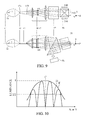
- FIG. 6 is a sectional view (X-Z and Y-Z section views) illustrating a configuration of a projector optical unit that is Embodiment 2 of the present invention.
- FIG. 7 is a sectional view (X-Z and Y-Z section views) illustrating a configuration of a projector optical unit that is Embodiment 3 of the present invention.
- FIGS. 8A to 8C illustrate relations between a secondary light source image and shapes of an entrance surface of a rod integrator in Embodiment 3.
- FIG. 9 is a sectional view (X-Z and Y-Z section views) illustrating a configuration of a projector optical unit that is Embodiment 4 of the present invention.
- FIG. 10 is a diagram illustrating a definition of an F-number.
- FIG. 1 illustrates a configuration of a projector optical unit (optical apparatus) that is a first embodiment (Embodiment 1) of the present invention.
- the projector optical unit is incorporated, as an optical engine, in a projector (image projection apparatus) together with a light source 1 and a projection optical system PL.
- the projection optical system PL may be part of the optical unit or may be detachably (interchangeably) attached to the optical unit.
- a light flux emitted from the light source 1 is condensed by a paraboloidal reflector 2 and then enters a first fly-eye lens 3 as a collimated light flux.
- a super-high-pressure mercury lamp or a xenon lamp is used as the light source 1 .
- an LED may be used as the light source 1 .
- a laser diode as an excitation light source that emits a blue light or the like and a phosphor performing wavelength conversion on part of the light from the excitation light source and not performing the wavelength conversion on the remaining part thereof may be used in combination with each other as the light source 1 .
- the light flux entering the first fly-eye lens 3 from the paraboloidal reflector 2 enters multiple lens cells of the first fly-eye lens 3 to be divided into multiple light fluxes.
- the multiple light fluxes enter multiple lens cells of a second fly-eye lens 4 provided correspondingly to the multiple lens cells of the first fly-eye lens 3 and are then condensed near the second fly-eye lens 4 to form multiple secondary light source images 5 .
- the multiple light fluxes exiting the second fly-eye lens 4 are condensed by a condenser lens 6 and then overlap one another on panel surfaces (modulation surfaces) of multiple (three in this embodiment) reflective liquid crystal panels 7 R, 7 G and 7 B through a polarization beam splitter 8 and a cross dichroic prism 9 both described later. Consequently, the panel surfaces of the reflective liquid crystal panels are uniformly illuminated.
- the light (P-polarized light) entering the cross dichroic prism 9 is separated, by multiple (two) dichroic surfaces 9 a and 9 b provided inside the cross dichroic prism 9 , into three color lights, namely, a red (R) light, a green (G) light and a blue (B) light.
- the dichroic surfaces 9 a and 9 b are arranged so as to mutually intersect inside the cross dichroic prism 9 .
- the three color lights enter the reflective liquid crystal panels 7 R, 7 G and 7 B corresponding to the respective color lights.
- the reflective liquid crystal panels as reflective light modulators are capable of changing (that is, modulating) a polarization direction of a polarized light entering each of pixels thereof in response to control of orientations of liquid crystals in the pixel depending on an input image signal input to the projector.
- the three color lights modulated and reflected by the three reflective liquid crystal panels 7 R, 7 G and 7 B are combined by the dichroic surface 9 a of the cross dichroic prism 9 .
- the P-polarized component is reflected toward the light source 1
- an S-polarized component exits the cross dichroic prism 9 toward the polarization beam splitter 8 as an image light.
- the image light entering the polarization beam splitter 8 is reflected by the polarization splitting surface 8 a , enters the projection optical system PL and is then projected from the projection optical system PL onto a projection surface (not illustrated) such as a screen. Consequently, an RGB full-color image as a projected image is displayed.
- the first fly-eye lens 3 , the second fly-eye lens 4 and the condenser lens 6 constitute an illumination optical system as an integrator optical system that divides and condenses the light flux.
- An optical axis of the condenser lens 6 is hereinafter referred to as “an optical axis C” of the illumination optical system.
- an optical axis direction that is a direction in which the optical axis C of the illumination optical system extends is defined as a Z direction, and two directions orthogonal to the optical axis C and orthogonal to each other are defined as an X direction and a Y direction.
- FIG. 1 illustrates an X-Z section (first section) parallel to the optical axis C of the illumination optical system, to normals to the dichroic surfaces 9 a and 9 b and to normals to the panel surfaces of the reflective liquid crystal panels 7 R, 7 G and 7 B.
- a lower part of FIG. 1 illustrates a Y-Z section (second section) parallel to the optical axis C and orthogonal to the X-Z section.
- FIGS. 2A and 2B illustrate characteristics of the two dichroic films ( 9 a and 9 b ) included in the cross dichroic prism 9 .
- the two dichroic films are an R reflective film ( 9 a ) and a B reflective film ( 9 b ) respectively forming an angle of 45 degrees with respect to the optical axis C and mutually intersecting so as to form an angle of 90 degrees therebetween.
- the R reflective film has a cutoff wavelength of approximately 590 nm and has a characteristic that reflects a light component whose wavelength is longer than the cutoff wavelength (that is, the R light) and transmits a light component whose wavelength is shorter than the cutoff wavelength.
- the B reflective film has a cutoff wavelength of approximately 500 nm and has a characteristic that transmits a light component whose wavelength is longer than the cutoff wavelength and reflects a light component whose wavelength is shorter than the cutoff wavelength (that is, the B light).
- the light component transmitted through the R and B reflective films corresponds to the G light.
- Each of the two dichroic films has an additional characteristic that its cutoff wavelength shifts toward a longer-wavelength side when a ray incident angle to its film surface is larger than 45 degrees and shifts toward a shorter-wavelength side when the ray incident angle thereto is smaller than 45 degrees.
- the light reaching the dichroic film 9 b at an incident angle of 45 degrees toward the reflective liquid crystal panel 7 G is reflected by the reflective liquid crystal panel 7 G and then reaches the dichroic film 9 b at an incident angle of 45 degrees.
- a total characteristic (i.e., a reflectance) of the dichroic film 9 b is provided by multiplying a characteristic of the dichroic film 9 b for the light reaching the dichroic film 9 b toward the reflective liquid crystal panel 7 G by a characteristic of the dichroic film 9 b for the light reflected by the reflective liquid crystal panel 7 G and then reaching the dichroic film 9 b .
- FIGS. 3A to 3C show that, when the incident angle of the light to the dichroic film 9 b is 35 or 55 degrees, a light amount loss around the cutoff wavelength is larger than that caused when the incident angle of the light is 45 degrees.
- a ray spread angle dependent on an F-number of the illumination optical system with reference to the incident angle of 45 degrees enables calculating a total light amount loss. It is thus apparent that reducing a total ray incident angle to the dichroic films 9 a and 9 b enables reducing light amount losses at the dichroic films 9 a and 9 b.
- the “F-number” referred to in this embodiment includes an F-number on the X-Z section and an F-number on the Y-Z section.
- the F-numbers on the X-Z and Y-Z sections are values respectively acquired by dividing a focal length f of the condenser lens 6 by a maximum effective width D (D 1 and D 2 ) of a luminance distribution of the secondary light source images 5 formed near the second fly-eye lens 4 inside the illumination optical system on the X-Z and Y-Z sections.
- D maximum effective width
- These F-numbers on the X-Z and Y-Z sections are expressed as follows.
- the maximum effective width (maximum effective diameter) D of the luminance distribution of the secondary light source images refers to a half-value width of an envelope E of a luminance section of the secondary light source images, that is, a full width at half maximum that is a width providing a half of a maximum luminance I.
- the principal rays are parallel to one another means that an angle formed by each of the principal rays reaching the respective height positions on the reflective liquid crystal panel with respect to the normal to the panel surface of the reflective liquid crystal panel is within a range of ⁇ 5°.
- the illumination optical system in this embodiment enables avoiding an increase in amount of the light ray reaching the dichroic film at an undesired incident angle and thereby enables reducing the light amount loss at the dichroic film.
- the illumination optical system in this embodiment makes a distribution of the ray incident angles to the reflective liquid crystal panel approximately identical at all height positions, which enables reducing color unevenness.
- an eccentric fly-eye lens is used whose each eccentric lens cell is eccentric on the X-Z section illustrated in FIG. 1 in a direction to be closer to or farther from the optical axis C with respect to a center of that eccentric lens cell. More specifically, on the X-Z section, the first fly-eye lens 3 is an eccentric fly-eye lens having a positive refractive power as a whole, and the second fly-eye lens 4 is an eccentric fly-eye lens having a negative refractive power as a whole. These first and second fly-eye lenses 3 and 4 compress a width of the collimated light flux from the reflector 2 .
- the illumination optical system in this embodiment satisfies a condition of f/D 1 >f/D 2 . The satisfaction of this condition enables reducing the shift of the cutoff wavelength of the dichroic film, which enables reducing the light amount loss and the color unevenness.
- the light flux is divided by the multiple lens cells of the first fly-eye lens 3 into the multiple light fluxes to form, near the second fly-eye lens 4 , the multiple secondary light source images 5 corresponding to the respective lens cells.
- a specific lens cell of the first fly-eye lens the specific lens cell is hereinafter referred to as “a first lens cell”
- a partial light flux passing through a second lens cell of the second fly-eye lens 5 corresponding to the first lens cell reaches the panel surface.
- FIGS. 4A to 4D illustrate the relation between the secondary light source images 5 and the aperture shape of the lens cells of the second fly-eye lens 4 viewed from the optical axis direction.
- each of the light source images has a rectangular shape (rod-like shape) which reflects a shape of a discharge arc in the light source and has a tilt corresponding to a position in a reflective surface of the paraboloidal reflector 2 reflecting the light flux forming that light source image 5 .
- an angle at which the reflective surface of the reflector 2 faces the discharge arc varies depending on a height from the optical axis C.
- the multiple light source images 5 have a radial distribution whose center is located on the optical axis C of the illumination optical system.
- FIG. 4B illustrates a relation between radially distributed light source images 5 ′ and a shape of apertures (aperture shape) of lens cells of a second fly-eye lens 4 ′ in a case of using the configuration disclosed in Japanese Patent Laid-Open No. 2002-268007.
- the aperture shape of the lens cells of the second fly-eye lens 4 ′ is rectangular homothetic to that of the panel surface.
- the first fly-eye lens 3 is configured as the eccentric fly-eye lens having the refractive power as a whole
- the second fly-eye lens 4 is configured as the eccentric fly-eye lens having the refractive power as a whole.
- each lens cell of the first fly-eye lens 3 has an aperture having a rectangular shape homothetic to the panel surface
- each lens cell of the second fly-eye lens 4 has an aperture having a square shape whose width in the long-side direction is compressed as compared to that of the panel surface as illustrated in FIG. 4D .
- Such an aperture shape of the lens cells of the second fly-eye lens 4 can prevent the secondary light source images 5 from largely protruding outside the apertures of these lens cells, differently from the configuration disclosed in Japanese Patent Laid-Open No. 2002-268007. Therefore, the illumination optical system in this embodiment enables reducing the light amount loss even though the F-number is increased by compressing the light flux on the X-Z section.
- FIGS. 5A and 5B illustrate a result of a calculation (simulation) of the multiplication. Specifically, FIG. 5A illustrates the calculation result acquired when a super-high-pressure mercury lamp whose discharge arc has a length of 1.1 mm is used as the light source 1 , and FIG.
- FIG. 5B illustrates the calculation result acquired when a super-high-pressure mercury lamp whose discharge arc has a length of 0.9 mm is used as the light source 1 .
- increasing the F-number on the X-Z section decreases the light utilization efficiency in the second fly-eye lens 4 and, on the other hand, decreases the light amount loss at the dichroic surfaces 9 a and 9 b , which consequently improves the light utilization efficiency.
- multiplying these effects makes the final light utilization efficiency (TOTAL) higher as the F-number is increased on the X-Z section.
- a degree of the decrease in the light utilization efficiency due to the increase in the F-number is smaller in the case where the discharge arc has a shorter length of 0.9 mm as illustrated in FIG. 5B than that in the case where the discharge arc has a longer length of 1.1 mm as illustrated in FIG. 5A .
- a larger F-number provides a higher light utilization efficiency. Therefore, reducing the incident angle to the dichroic surface makes it possible to further decrease the color unevenness and to decrease a size of the cross dichroic prism, which is advantageous in miniaturization of not only the projector optical unit, but also the projector. Consequently, when the configuration in this embodiment is employed, it is desirable to use a light source whose light emission area, such as the length of the discharge arc, is small.
- this embodiment can realize a projector optical unit and a projector each capable of presenting a projected image having a higher brightness and less color unevenness as compared to the conventional configurations.
- FIG. 6 illustrates a configuration of a projector optical unit of a second embodiment (Embodiment 2) of the present invention. Since this embodiment is different from Embodiment 1 only in that it uses a reflector 11 and a first fly-eye lens 12 and a second fly-eye lens 13 of the illumination optical system, other constituent elements in this embodiment common to those in Embodiment 1 are denoted by the same reference numerals or characters as those in Embodiment 1, and description thereof is omitted.
- the first fly-eye lens 12 is configured as an eccentric fly-eye lens having a negative refractive power as a whole
- the second fly-eye lens 13 is configured as an eccentric fly-eye lens having a negative refractive power as a whole.
- This configuration enlarges a width of a collimated light flux emitted from the reflector 11 so as to make a maximum effective width D 2 of a luminance distribution of secondary light source images on the Y-Z section larger than a maximum effective width D 1 thereof on the X-Z section as the first section. Therefore, as in Embodiment 1, the F-number on the X-Z section is larger than the F-number on the Y-Z section.
- this embodiment improves a total light utilization efficiency by making the F-number on the Y-Z section smaller than the F-number on the X-Z section while preventing an increase in the light amount loss at the dichroic films ( 9 a and 9 b ) without changing a ray incident angle to the dichroic films on the X-Z section.
- Embodiment 1 suppresses the decrease in the light utilization efficiency by forming the aperture shape of each lens cell of the second fly-eye lens 4 into a square shape by contracting the aperture shape in its long-side direction.
- this embodiment improves the light utilization efficiency by forming the aperture shape of each lens cell of the second fly-eye lens 4 into a square shape by elongating the aperture shape in its short-side direction. If the aperture shape of the lens cell is elongated in the long-side direction, the protrusion of the rod-like shaped secondary light source image at positions where the longitudinal direction of the secondary light source image is largely tilted with respect to the long-side direction of the elongated rectangular aperture of the lens cell is not reduced, and thus a degree of improvement in the light utilization efficiency is low.
- the aperture shape of the lens cell is square in this embodiment, which enables efficiently reducing the protrusion of the rod-like shaped secondary light source image at the positions where the longitudinal direction of the secondary light source images is largely tilted with respect to the long-side direction of the rectangular aperture of the conventional lens cell. This reduction in the protrusion enables significantly improving the light utilization efficiency.
- This embodiment decreases the F-number on the Y-Z section by increasing the maximum effective width D 2 of the luminance distribution of the secondary light source images 5 on the Y-Z section. Decreasing the F-number in this manner makes it necessary to decrease an F-number of the projection optical system PL, which may cause problems such as an increase in size of the projection optical system PL and a decrease in resolution performance.
- this embodiment reduces outer dimensions of the first fly-eye lens 12 by using the reflector 11 with a small aperture diameter. This consequently makes the maximum effective width of the luminance distribution of the secondary light source images 5 in this embodiment approximately the same as that in Embodiment 1, which prevents the above-described problems from occurring. Therefore, in addition to the effects achieved by Embodiment 1, this embodiment enables achieving an effect of miniaturizing the illumination optical system, by using the reflector with the small aperture diameter.
- FIG. 7 illustrates a configuration of a projector optical unit that is a third embodiment (Embodiment 3) of the present invention.
- This embodiment is different from Embodiments 1 and 2 in that it uses a rod integrator 15 in an illumination optical system instead of the first and second fly-eye lenses.
- Constituent elements in this embodiment common to those in Embodiments 1 and 2 are denoted by the same reference numerals or characters as those in Embodiments 1 and 2, and description thereof is omitted
- the rod integrator 15 is an optical element formed of glass and having a rectangular-shaped section orthogonal to the optical axis C. Light entering the rod integrator 15 from its entrance surface 15 a is repeatedly internally totally reflected thereinside to form a uniform luminance distribution at its exit surface 15 b .
- the rod integrator 15 is the same as the first and second fly-eye lenses in Embodiment 1 and 2 in that it is provided to uniformly illuminate the panel surfaces of the reflective liquid crystal panels 7 R, 7 G and 7 B.
- the exit surface 15 b of the rod integrator 15 corresponds to the first fly-eye lens, and the entrance surface 15 a thereof corresponds to the second fly-eye lens.
- the rod integrator 15 has a tapered shape in which a size of its section orthogonal to the optical axis C varies (increases) from the entrance surface 15 a toward the exit surface 15 b.
- a hollow rod integrator may alternatively be used which is provided with, on its side surfaces, a reflective mirror formed by vapor deposition of a multi-layer dielectric film or a metal film.
- a light flux emitted from the light source 1 is condensed by an elliptical reflector 14 to form a secondary light source image 16 near the entrance surface 15 a of the rod integrator 15 and then enters the rod integrator 15 .
- the exit surface 15 b of the rod integrator 15 has a rectangular shape homothetic to the shape of the panel surface of each reflective liquid crystal panel.
- the light flux exiting the exit surface 15 b of the rod integrator 15 is condensed by a relay lens system 17 on the panel surface of each reflective liquid crystal panel. It is the same as Embodiments 1 and 2 in that the light flux passes through the polarization beam splitter 8 and is then color-separated by the cross dichroic prism 9 .
- each reflective liquid crystal panel is arranged such that the long sides of the panel surface are parallel to the X-Z section as the first section. Accordingly, long sides of the exit surface 15 b of the rod integrator 15 are also parallel to the X-Z section.
- a light source image (hereinafter referred to as “a tertiary light source image”) 18 is formed also at an intermediate position in the relay lens system 17 .
- the tertiary light source image 18 corresponds to the secondary light source image formed near the second fly-eye lens in the illumination optical system in each of Embodiments 1 and 2 using the first and second fly-eye lenses.
- F-numbers on the X-Z and Y-Z sections referred to in this embodiment are values acquired by dividing a focal length f of a lens included in the relay lens system 17 at a position closest to the liquid crystal panel and serving as a condenser lens by maximum effective widths D 1 and D 2 of a luminance distribution of the tertiary light source image 18 on the X-Z and Y-Z sections (see expressions (1) and (2)).
- the F-number decreases, which means that the ray incident angle to the reflective liquid crystal panel becomes larger.
- the relay lens system 17 includes multiple lenses each serving as the condenser lens
- the F-number is acquired by using not the focal length of only the lens closest to the liquid crystal panel, but a total focal length of the multiple lenses.
- the lens serving as the condenser lens refers to a lens unit that is located between the liquid crystal panel and the light source image formed closest to the liquid crystal panel and is constituted by one or more lenses condensing the light source image formed closest to the liquid crystal panel on the panel surface.
- this embodiment uses the taper-shaped rod integrator 15 .
- Two of four side surfaces other than the entrance and exit surfaces 15 a and 15 b of the rod integrator 15 which face each other in the X-Z section are formed so as to become closer to each other from the exit surface 15 b toward the entrance surface 15 a .
- This shape causes the entrance surface 15 a of the rod integrator 15 to have a square shape.
- tapered surface After light rays entering the rod integrator 15 are reflected by the side surfaces having the above-described taper (hereinafter referred to as “tapered surface”), an angle formed by each of the light rays with respect to the optical axis C becomes smaller than that before the reflection. Thus, repetition of the reflection on the tapered surface allows the light rays finally exiting the exit surface 15 b to have a smaller spread angle on the X-Z section. This reduction in the spread angle allows the tertiary light source image 18 on the X-Z section to have a smaller maximum effective width D 1 of the luminance distribution on the X-Z section, which allows the F-number on the X-Z section to have a larger value than that of the F-number on the Y-Z section. This enables decreasing the ray incident angle to the dichroic film ( 9 a and 9 b ), which enables reducing the light amount loss at the dichroic film.
- FIGS. 8A to 8C illustrate a relation between the secondary light source image 16 and an aperture shape of the entrance surface 15 a of the rod integrator 15 .
- the secondary light source image 16 is formed near the entrance surface 15 a of the rod integrator 15 by the elliptical reflector 14 facing the discharge arc of the light source 1 from all 360-degree directions. For this reason, the secondary light source image 16 has an approximately circular shape (symmetric to its center) as illustrated in FIG. 8A .
- the entrance surface of the rod integrator has a small area
- vignetting is generated in a light source image formed near the entrance surface, which decreases the light utilization efficiency.
- the entrance surface 15 a of the rod integrator 15 is formed so as to have an area smaller than that of the exit surface 15 b
- the entrance surface 15 a has a square shape by being narrowed along a long-side direction of the exit surface 15 b as illustrated in FIG. 8B .
- This prevents generation of a large vignetting of the light source image, which prevents the light utilization efficiency from significantly decreasing. That is, similarly to the aperture shape of the lens cell of the second fly-eye lens described in Embodiment 1, it is advantageous from a light utilization efficiency point of view that the entrance surface 15 a of the rod integrator 15 has the square shape.
- the entrance surface 15 a ′ has a rectangular shape with an aspect ratio in which its long side is extremely longer than its short side.
- Such a rectangular shape has a low match ratio to the circular secondary light source image 16 , which results in a light utilization efficiency significantly lower than that in the case of using a square shape with the identical area.
- the reason why such a difference occurs is because the long side of the panel surface of the reflective liquid crystal panel is arranged in parallel to the X-Z section as in Embodiments 1 and 2.
- this embodiment reduces the light amount loss at the dichroic film by setting the F-number on the X-Z section to be larger than the F-number on the Y-Z section while making the long side of the panel surface of the reflective liquid crystal panel parallel to the X-Z section.
- This forms the rod integrator 15 having the tapered shape on the X-Z section, which reduces the generation of the vignetting of the secondary light source image 16 on the entrance surface 15 a even though the entrance surface 15 a has a reduced area and thus prevents the decrease in the light utilization efficiency.
- this embodiment forms the rod integrator 15 having the tapered shape in which its two side surfaces facing each other on the X-Z section become closer to each other toward the entrance surface 15 a
- it may be formed so as to have a tapered shape in which two side surfaces facing each other on the Y-Z section become farther from each other toward the entrance surface to allow the entrance surface of the rod integrator to have a square shape.
- the ray incident angle to the rod integrator can be decreased by using the elliptical reflector 14 having a longer focal length than that of the reflector used in this embodiment. This allows the luminance distribution of the tertiary light source image to have a maximum effective width similar to that in this embodiment, which enables making the entire F-number the same as that in Embodiment 1.
- FIG. 9 illustrates a configuration of a projector optical unit that is a fourth embodiment (Embodiment 4) of the present invention.
- An upper part of FIG. 9 illustrates a sectional view of an illumination optical system on an X-Z section including an optical axis of the illumination optical system (such as an optical axis of a condenser lens in the illumination optical system) and being parallel to an X direction and a Z direction.
- a lower part of FIG. 9 illustrates a sectional view of the illumination optical system on a Y-Z section including the optical axis of the illumination optical system and being orthogonal to the X-Z section.
- a configuration of this embodiment is different from that of Embodiment 3 in that it uses mirror light modulators 21 as reflective light modulators instead of the reflective liquid crystal panels and in that an internal total reflective prism 19 instead of the polarization beam splitter.
- the internal total reflective prism 19 , a cross dichroic prism 20 and mirror light modulators 21 are simply illustrated (illustrated not as a correct X-Z section view, but as a view of a section inclined to the X-Z section).
- the mirror light modulator includes, on its surface as a light modulation surface, multiple micromirrors each corresponding to each of pixels arranged in a matrix. An orientation of each micromirror is switched between two tilt positions, namely, an ON position and an OFF position by application of a voltage to a driver of the micromirror. Light reaching the micromirror being at the ON position is reflected by the micromirror and then introduced to a projection optical system, whereas light reaching the micromirror being at the OFF position is not introduced to the projection optical system.
- dichroic films in the cross dichroic prism 20 are each required to have a film characteristic corresponding to a non-polarized light. This requirement results in the same problem as that occurring in the configuration using the reflective liquid crystal panel. Since, in this case, an entrance optical path and a reflection optical path are different from each other, the internal total reflective prism 19 is used as an optical path switching element instead of the polarization beam splitter.
- This embodiment reduces the light amount loss by using the taper-shaped rod integrator as in Embodiment 3 for increasing the F-number on the X-Z section to decrease the ray incident angle to the dichroic film.
- this embodiment suppresses a decrease in the light utilization efficiency caused by the increase in the F-number by making a long-side direction of the mirror light modulator correspond to the X-Z section.
- the switching of the entrance optical path of light rays to the mirror light modulator and the reflection optical path thereof from the mirror light modulator increases an angle formed by light rays. For this reason, arranging an optical path switching surface of the internal total reflective prism 19 on the Y-Z section as illustrated in FIG. 9 enables preventing the ray incident angle to the dichroic film from increasing, which is desirable in terms of the light utilization efficiency. This enables realizing an image projection apparatus capable of projecting a bright image even when the apparatus uses the mirror light modulator.
- Embodiments 1 to 4 use the cross dichroic prism ( 9 or 20 ), other dichroic prisms such as a Philips-type dichroic prism may alternatively be used as disclosed in Japanese Patent Laid-Open No. 2002-268007.
- the Philips-type dichroic prism described here refers to a prism (color separation/combination prism) in which color separation/combination surfaces such as an R reflective film and a B reflective film do not intersect with each other and is applicable to each of Embodiments 1 to 4 described above.
- Embodiments 1 and 2 respectively use the paraboloidal reflectors 2 and 11 as a reflector, a combination of an elliptic reflector and a concave lens may alternatively be used.
- Embodiment 3 uses the elliptical reflector 14 , a combination of a paraboloidal reflector and a convex lens may alternatively be used.
- a polarization conversion element array may be provided at a position at which the secondary light source image 5 or the tertiary light source image 18 is formed.
Landscapes
- Physics & Mathematics (AREA)
- General Physics & Mathematics (AREA)
- Engineering & Computer Science (AREA)
- Multimedia (AREA)
- Signal Processing (AREA)
- Optics & Photonics (AREA)
- Projection Apparatus (AREA)
- Video Image Reproduction Devices For Color Tv Systems (AREA)
Abstract
Description
f/D1>f/D2
where f represents a focal length of the condenser lens, D1 represents a maximum effective width of the area in which the light source images are formed in the first section, and D2 represents a maximum effective width of the area in which the light source images are formed in the second section.
F-number on the X-Z section: F=f/D1 (1)
F-number on the Y-Z section: F=f/D2 (2)
F=1/(2 tan θ). (3)
Claims (12)
f/D1>f/D2,
f/D1>f/D2,
Applications Claiming Priority (2)
| Application Number | Priority Date | Filing Date | Title |
|---|---|---|---|
| JP2014-238505 | 2014-11-26 | ||
| JP2014238505A JP6525560B2 (en) | 2014-11-26 | 2014-11-26 | Optical device and image projection device |
Publications (2)
| Publication Number | Publication Date |
|---|---|
| US20160150202A1 US20160150202A1 (en) | 2016-05-26 |
| US10015455B2 true US10015455B2 (en) | 2018-07-03 |
Family
ID=56011515
Family Applications (1)
| Application Number | Title | Priority Date | Filing Date |
|---|---|---|---|
| US14/941,958 Active 2036-01-30 US10015455B2 (en) | 2014-11-26 | 2015-11-16 | Optical apparatus and image projection apparatus having multiple reflective light modulators and multiple dichroic surface that separate light into multiple color lights and combines them |
Country Status (2)
| Country | Link |
|---|---|
| US (1) | US10015455B2 (en) |
| JP (1) | JP6525560B2 (en) |
Families Citing this family (3)
| Publication number | Priority date | Publication date | Assignee | Title |
|---|---|---|---|---|
| US20170177964A1 (en) * | 2015-12-18 | 2017-06-22 | Industrial Technology Research Institute | Optical inspection system and optical inspection method thereof |
| CN113960861A (en) * | 2020-07-20 | 2022-01-21 | 深圳光峰科技股份有限公司 | Compound eye module, light source device and projection equipment |
| JP2023011496A (en) * | 2021-07-12 | 2023-01-24 | パナソニックIpマネジメント株式会社 | Projection type video display device |
Citations (8)
| Publication number | Priority date | Publication date | Assignee | Title |
|---|---|---|---|---|
| JPH10274810A (en) | 1997-03-31 | 1998-10-13 | Sharp Corp | Projection type image display device |
| JPH11316356A (en) | 1998-03-02 | 1999-11-16 | Nikon Corp | Projection display device |
| US6286961B1 (en) * | 1997-11-18 | 2001-09-11 | Seiko Epson Corporation | Illuminating optical system and projection type display |
| US6357878B1 (en) * | 1999-01-18 | 2002-03-19 | Minolta Co., Ltd. | Optical system for a projector |
| JP2002268007A (en) | 2001-03-12 | 2002-09-18 | Ricoh Co Ltd | Image projecting device |
| US6464375B2 (en) * | 1998-03-12 | 2002-10-15 | Matsushita Electric Industrial Co., Ltd. | Lens element and illumination optical apparatus and projection display apparatus |
| US20030147051A1 (en) * | 2001-12-28 | 2003-08-07 | Kazuhiro Fujita | Color separation device, imaging optical engine, and projection apparatus |
| US20070153663A1 (en) * | 2005-09-16 | 2007-07-05 | Sony Corporation | Hologram recording/reproducing device and recording/reproducing optical apparatus |
Family Cites Families (8)
| Publication number | Priority date | Publication date | Assignee | Title |
|---|---|---|---|---|
| JP3473075B2 (en) * | 1993-12-24 | 2003-12-02 | セイコーエプソン株式会社 | Lighting device and projection display device |
| JPH11295658A (en) * | 1998-04-07 | 1999-10-29 | Sony Corp | LCD projector |
| JP3666339B2 (en) * | 2000-01-28 | 2005-06-29 | セイコーエプソン株式会社 | projector |
| JP2002250918A (en) * | 2001-02-26 | 2002-09-06 | Nikon Corp | Projection display device |
| JP4143444B2 (en) * | 2003-03-07 | 2008-09-03 | キヤノン株式会社 | Illumination optics |
| JP5020502B2 (en) * | 2005-11-18 | 2012-09-05 | キヤノン株式会社 | Image projection optical system and image projection apparatus |
| JP5110979B2 (en) * | 2007-06-26 | 2012-12-26 | キヤノン株式会社 | Illumination optical system and projection display device using the same |
| TWI418916B (en) * | 2010-10-14 | 2013-12-11 | Young Optics Inc | Projection apparatus |
-
2014
- 2014-11-26 JP JP2014238505A patent/JP6525560B2/en active Active
-
2015
- 2015-11-16 US US14/941,958 patent/US10015455B2/en active Active
Patent Citations (9)
| Publication number | Priority date | Publication date | Assignee | Title |
|---|---|---|---|---|
| JPH10274810A (en) | 1997-03-31 | 1998-10-13 | Sharp Corp | Projection type image display device |
| US6157420A (en) * | 1997-03-31 | 2000-12-05 | Sharp Kabushiki Kaisha | Projection-type image display apparatus |
| US6286961B1 (en) * | 1997-11-18 | 2001-09-11 | Seiko Epson Corporation | Illuminating optical system and projection type display |
| JPH11316356A (en) | 1998-03-02 | 1999-11-16 | Nikon Corp | Projection display device |
| US6464375B2 (en) * | 1998-03-12 | 2002-10-15 | Matsushita Electric Industrial Co., Ltd. | Lens element and illumination optical apparatus and projection display apparatus |
| US6357878B1 (en) * | 1999-01-18 | 2002-03-19 | Minolta Co., Ltd. | Optical system for a projector |
| JP2002268007A (en) | 2001-03-12 | 2002-09-18 | Ricoh Co Ltd | Image projecting device |
| US20030147051A1 (en) * | 2001-12-28 | 2003-08-07 | Kazuhiro Fujita | Color separation device, imaging optical engine, and projection apparatus |
| US20070153663A1 (en) * | 2005-09-16 | 2007-07-05 | Sony Corporation | Hologram recording/reproducing device and recording/reproducing optical apparatus |
Also Published As
| Publication number | Publication date |
|---|---|
| JP6525560B2 (en) | 2019-06-05 |
| JP2016099585A (en) | 2016-05-30 |
| US20160150202A1 (en) | 2016-05-26 |
Similar Documents
| Publication | Publication Date | Title |
|---|---|---|
| US6497488B1 (en) | Illumination system and projector | |
| CN104820335B (en) | Light source optical system, light supply apparatus and image display device using it | |
| JPH10333115A (en) | Projection type liquid crystal display | |
| US8434877B2 (en) | Illumination optical system and projection display apparatus | |
| JP2006145644A (en) | Polarization separator and projection display device using the same | |
| US6773111B2 (en) | Projection type image display apparatus | |
| US8123366B2 (en) | Light source with truncated ellipsoidal reflector | |
| JP2007025308A (en) | Projection-type image display device and color separation unit | |
| US10705419B2 (en) | Prism device for use in two-plate video projector apparatus capable of reducing internal stray light of prism device | |
| US7841725B2 (en) | Image display device and projector | |
| US10015455B2 (en) | Optical apparatus and image projection apparatus having multiple reflective light modulators and multiple dichroic surface that separate light into multiple color lights and combines them | |
| JP2004070095A (en) | Optical waveguide, optical unit, and image display device using the same | |
| JP4258293B2 (en) | Projection-type image display device | |
| US8506128B2 (en) | Light source device, illumination system, and projector | |
| KR100764316B1 (en) | Lighting device and projector | |
| JPWO2005019929A1 (en) | projector | |
| US10481473B2 (en) | Image projection apparatus | |
| JP3486608B2 (en) | Projection display device | |
| EP1874063A2 (en) | Projection apparatus | |
| JP2008165136A (en) | projector | |
| US20090147159A1 (en) | Projector | |
| US8128239B2 (en) | Light source device and projector | |
| JP2005165137A (en) | Illumination optical system and image display device | |
| JP2001174756A (en) | Optical device and image display device using the same | |
| JP3365412B2 (en) | Projection display device |
Legal Events
| Date | Code | Title | Description |
|---|---|---|---|
| AS | Assignment |
Owner name: CANON KABUSHIKI KAISHA, JAPAN Free format text: ASSIGNMENT OF ASSIGNORS INTEREST;ASSIGNOR:KAWASUMI, TAKEHITO;REEL/FRAME:037628/0878 Effective date: 20151106 |
|
| STCF | Information on status: patent grant |
Free format text: PATENTED CASE |
|
| MAFP | Maintenance fee payment |
Free format text: PAYMENT OF MAINTENANCE FEE, 4TH YEAR, LARGE ENTITY (ORIGINAL EVENT CODE: M1551); ENTITY STATUS OF PATENT OWNER: LARGE ENTITY Year of fee payment: 4 |
|
| AS | Assignment |
Owner name: BANK OF AMERICA, N.A., AS COLLATERAL AGENT, ILLINOIS Free format text: SECURITY INTEREST;ASSIGNORS:ADEIA INC. (F/K/A XPERI HOLDING CORPORATION);ADEIA HOLDINGS INC.;ADEIA MEDIA HOLDINGS INC.;AND OTHERS;REEL/FRAME:071454/0343 Effective date: 20250527 |
|
| MAFP | Maintenance fee payment |
Free format text: PAYMENT OF MAINTENANCE FEE, 8TH YEAR, LARGE ENTITY (ORIGINAL EVENT CODE: M1552); ENTITY STATUS OF PATENT OWNER: LARGE ENTITY Year of fee payment: 8 |