US1000612A - Ball-bearing. - Google Patents
Ball-bearing. Download PDFInfo
- Publication number
- US1000612A US1000612A US60188811A US1911601888A US1000612A US 1000612 A US1000612 A US 1000612A US 60188811 A US60188811 A US 60188811A US 1911601888 A US1911601888 A US 1911601888A US 1000612 A US1000612 A US 1000612A
- Authority
- US
- United States
- Prior art keywords
- bearing
- balls
- faces
- ball
- members
- Prior art date
- Legal status (The legal status is an assumption and is not a legal conclusion. Google has not performed a legal analysis and makes no representation as to the accuracy of the status listed.)
- Expired - Lifetime
Links
- 230000000295 complement effect Effects 0.000 description 22
- 239000007787 solid Substances 0.000 description 6
- 230000013707 sensory perception of sound Effects 0.000 description 4
- 238000000926 separation method Methods 0.000 description 4
- 238000010276 construction Methods 0.000 description 3
- 238000007493 shaping process Methods 0.000 description 2
- 102000004726 Connectin Human genes 0.000 description 1
- 108010002947 Connectin Proteins 0.000 description 1
- 235000010627 Phaseolus vulgaris Nutrition 0.000 description 1
- 244000046052 Phaseolus vulgaris Species 0.000 description 1
- 208000003251 Pruritus Diseases 0.000 description 1
- 241001249696 Senna alexandrina Species 0.000 description 1
- 229910000831 Steel Inorganic materials 0.000 description 1
- 238000010961 commercial manufacture process Methods 0.000 description 1
- 230000000694 effects Effects 0.000 description 1
- 238000003754 machining Methods 0.000 description 1
- 238000004519 manufacturing process Methods 0.000 description 1
- 239000002184 metal Substances 0.000 description 1
- 230000002093 peripheral effect Effects 0.000 description 1
- 230000000717 retained effect Effects 0.000 description 1
- 238000005096 rolling process Methods 0.000 description 1
- 239000004576 sand Substances 0.000 description 1
- 239000010959 steel Substances 0.000 description 1
- 230000002459 sustained effect Effects 0.000 description 1
- 238000005496 tempering Methods 0.000 description 1
Images
Classifications
-
- F—MECHANICAL ENGINEERING; LIGHTING; HEATING; WEAPONS; BLASTING
- F16—ENGINEERING ELEMENTS AND UNITS; GENERAL MEASURES FOR PRODUCING AND MAINTAINING EFFECTIVE FUNCTIONING OF MACHINES OR INSTALLATIONS; THERMAL INSULATION IN GENERAL
- F16C—SHAFTS; FLEXIBLE SHAFTS; ELEMENTS OR CRANKSHAFT MECHANISMS; ROTARY BODIES OTHER THAN GEARING ELEMENTS; BEARINGS
- F16C19/00—Bearings with rolling contact, for exclusively rotary movement
- F16C19/02—Bearings with rolling contact, for exclusively rotary movement with bearing balls essentially of the same size in one or more circular rows
- F16C19/10—Bearings with rolling contact, for exclusively rotary movement with bearing balls essentially of the same size in one or more circular rows for axial load mainly
Definitions
- This invention relates to improvements in and particularly to thrust bearings of that type in which the balls and their bearings are so combined as to permit the balls to revolve freely between the bearing surfaces with which they are in contact without having any sliding movement with res ect to such surfaces.
- y present invention relates more particularly to a multiple thrust bearing having a plurality 'of substantially concentric rows of-balls which may roll in contact with hearing surfaces of the general character show'n,
- bearing surfaces which coact a row of balls if one of such aring mem hers is madein sections each of which contains a single bearingv surface or ball race complementary to'a corresponding bearing surface or ballv-race of the opposin bearing member.
- One of the bearing mem rs, usually, the lower one, may be made in a single piece and a plurality of substantiall' centric surfaces or ball-races formed therein by first machining out the-metal at the face of the bearing member or plate'and then said bearing member and afterward grinding or otherwise shaping each surface or ball-race separately to form a In thus ishing-such a bearing member the con i perfectly circular bearing surface;
- each ball-race constitutes a'p'erfect hearing surface for the balls of its own particular circuit.
- bearing member In order to obtain a" perfect complementary bearing- "surface for each bearing surface thus formed, it. is necessary bearing member into a'plura ity' ofsections and to form in each section a bearing surface which is the complement of one already formed, and in forming such complementary bearing surface the depth to which I the groove or race is ties in depth may be readilymade att e o no'site or 0, her side of such section after t 'e bearing surface has been completed; In this way each of the sections of the eompleor opposing ground is unimportant, as the necessity compensation for irre ular1- surfaces have been finished the u per or outer faces of the sections may be rought to a common plane by, grinding or otherwise, so as to assure the proper application of the load to all of the sectlons andthe balls on which they rest.
- each multiple thrust bearing of the type just described a single element or unit:-
- This I accomplish by providing a suitable retainer for holding in place the solid bearing membcr and one of the sections of the sectional bearing member, and by so shaping the va rious sections of the sectional bearing mem her that they are-interlocked and can not become separated until the main ballretainer is removed.
- a further important feature of my invention is the means provided to distribute as uniformly as possible the loads borne by the different circuits of balls embodied in a thrust bearing of this type and to equalize the resistance opposed by the several circuits ,of the bearing faces to centrifugal force tending to force the bails out of their races.
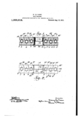
- Figure 1 is a central vertical section of a multiple thrustbcaring constructed in acv cordance with my present invention.
- Fig. 2 is a central vertical section of a multiple thrustbcaring constructed in acv cordance with my present invention.
- .Thcse grooves are designated gen-' erally by 3, 4 and In constructing this bearing member these grooves are machined receive the balls which are-intended to roll thereimand after being so formed the bearing member is tempered to harden the bearingsurfaces-or balLraces. 'After being hardcned each bearing surface is brought to the" ing member is operated upon in this manher to form a plurality of substantially concentric ball-races orsets of bearing surfaces,
- bearing member substantially similar to the' solidone except that it is divided'by nar- -row circular spaces,'such as 12 and. 12'.
- each'section of the upper bearing member, together with its bearing surfaces, is formed in substantially the same manner as the lower solid bearing member and any one-of its ball-grooves, that is to say, such section is first properly shaped, then tempered, and its bearing surfaces afterward finished, as
- bearing surfaces are preferably so formed as to require the minimum amount of grinding to finish the same.
- ball-retainmg means for holding'all of the bearing elements and the balls securely in position.
- a ball-retainer such as 20, of a type somewhat similar to that illustrated in my companion. application, Serial No. 200,678, filed March 30, 1904, that isto say,
- I provide an intcrnal'retaining ring that is 3 preferably formed froma section of soft 'steel tubing having its ends flared outwardly, as at 21, to coact with corresponding flaring walls 22 at-the outer ends of the 40 boresof the opposite bearing members and prevent undue endwise-separation of the latter.
- This retaining ring 20 in the present case, however, instead of being formed of substantially one diameter and being loose' with respect to both bearingmembers as in my aforesaid application, is formed of two diametersso as to have a fixed connection with one of the bearing members and be loose with respect to theother,'the' said re- 'taining ring as herein shown being arranged with its end of largest diameter, indicated at 23, having afixed connection with the lower bearing member 2 by means of frictional engagement therewith, and with its, end of smallest diameter, indicated atQ/t,
- Such a construction of retaining means is-especially adapted for use'in heal ings of this'type because, by reason of the angular positions of the respective sets of bearing surfaces 13'--13", 14 -14 and- I515T, as well as because of the angular positions of the corresponding sets of hearing surfaces 3'--3", l -4:" and 5 -5", all of the'rows of balls are self-centering, and
- a bearing of this type, that is, a multiple thrust bearing having all its rows of balls substantially in a common plane
- the balls in different rows revolve at difierent speeds under ordinary conditions, that is to say, all the upper bearing surfaces move in unison, as is ordinarily the case.
- the balls in the outer row revolve most rapidly and their tendency to fly outward under the action ofcentrif-' ugal. force is greater than is the'case vith' respect to the balls in the intermediatdirow or circuitfwhichballs in turn revolve morerapidly and have greater tendency to .fly outward, than the balls 9 of the innerrow or-'circui,t. l-ri order to equalize the resistance opposed to such centrifugal action
- Fig. 2 it will be seen that the application of these principles to a bearing of this type is clearly illustrated, the diiferent quadrilaterals, 25, 26 and27, which are of different widths and heights illustrating the different distances. from the centers of the balls, as measured in a horizontal direction, at which contact is made by the balls with bearing surfaces placed at different angles to the horizontal.
- each ball 7 has a lighter load to sustain than any ball 8; and each ball 8 has a lighter road to sustain than any ball 9.
- the tendency of the balls in the diferent rows to fly outward under actionof centrifugal force varies according to the speed thereof, the balls in the outermost row having a greater speed naturally have a greater tendency to fiy outward than the balls in the intermediate row, and the balls in the inner row having a less tendency to-fly outward that the balls in the intermediate row, for which reasons the greatest angle to the horizontal is made by the ball surfaces 13 and 3". While the manner in which the loads borne by the different sets of balls are distributed may; be varied and the relative angles of the bearing surfaces of the difl'erent'concentric sets may also be itches, the I varied, the construction just described is that which is most desirable for all highspeed bearings.
- What I claim is: 1. The combination with .a pair of complementary bearing members having a common axis and each of which has a plurality of substantially concentric bearing faces and one of which is formed in a single piece and the other divided into a plurality of relatively movable sections concentric with said axis and each containing one of said bearing faces, of a plurality of substantially'concentric circuits of balls between and in'contact with the bearing faces of said bearing men? bers.
- each bearing point of each ball being in the face of an imaginary cone having its vertex in saidaxis.
- the combination wlth a pair of complementary bearing members having-a common axis and'each of which has a'pluralit'y' of pairs of substantially concentric bearing faces ositioned to make contact with balls of di erent circuits at the outer sides of the ing intervals for ballcircuits and at successively increasing angles to the plane of rotation of the bearing from the axis toward the periphery thereof, of a plurality of substantially concentric circuits of balls between and in con tact with the bearing faces of said bearing members.
- a thrust bearing embodying a pair of complementary bearing members having a common axis and each of which has a plurality of pairs of substantially concentric sets of bearing faces, in combination with a 'plurality of substantially concentric circuits of balls between and in contact with the bearing faces of said bearing members, the
- a thrust gearing embodying a pair of complementary common axis and each of which has a pin ralit of substantially concentric sets of.
Landscapes
- Engineering & Computer Science (AREA)
- General Engineering & Computer Science (AREA)
- Mechanical Engineering (AREA)
- Rolling Contact Bearings (AREA)
Description
H.- LA UASSE.
BALL BEARING.
I APPLICATION FILED HAY 10, 1904. RENEWED JAN. 10, 1911. 1,000, 12.
Patented Aug. 15, 1911.
. ball bearing UNITED PATENT OFFICE.
HENRY LA CASSE, OF AUBURN, NEW YORK.
BALL-BEARING.
1'0 (111 whom it may concern:
Be it known that I, l-lnnnr LA CASSE, a citizen of the United States, and resident of Auburn, in the county of Cayuga and State of New York, have invented certain new and useful Improvements in Ball-Bearings, .of which the following is a specification,
This invention relates to improvements in and particularly to thrust bearings of that type in which the balls and their bearings are so combined as to permit the balls to revolve freely between the bearing surfaces with which they are in contact without having any sliding movement with res ect to such surfaces.
y present invention relates more particularly to a multiple thrust bearing having a plurality 'of substantially concentric rows of-balls which may roll in contact with hearing surfaces of the general character show'n,
- described and claimed in Patent No. 518,321,
' granted to me April 17 1894, although-as to many of the features thereof my present in; vention is not limited tothe type of bearing shown in said patent. In that patent there is illustrated an antifriction ball bearing I having the general characteristics just menhas tioned, that is to say, a bearing in whichi-the balls and the bearing surfaces are so atom bined thatthe balls revolve-freely on such bearing surfaces without sliding. In my prior patentthis result was accomplished by providing bearingsurfaces which made contact with the balls in such a lnanner'that each bearing point of each ball was in the surface of an imaginary cone having its vertex inthe axis of the bearing, and I have shownfthis feature in the present case, and
preferably retain the same as an important feature of my present improved thrust bearlue of the most important features of my presentinvention relates tothe meanswhich I employ to obtain a rolling movement of each one of theballs in a plurality of circuits of balls embodied in amultiple thrust bearing. -In the manufacture of thrust bearings withtwo or, more concentric rows of balls in one plane it has been found that it is extremely diflicult toeprovide proper bearing surfaces for such ,alls in two opposing complementary members. This is due to the Specification of Letters l'atent. Application filed May 10, 1904, Serial No. 207,205. Renewed January 10, 1911 tempering :to divide the complements Patented Aug. 15, 1911.
semi no. 301,338.
fact that the bearing surfaces or ball'races must first be machined out, then tempered, and afterward'ground down to obtain a perfeet bearin circuit for each ron of balls. In performing these several operations there is always a slight difference in the results at each operation, and the aggregate of errors'is' such as toprevent proper coacting of all of the bearing surfaces with their respective rows of balls, and hencejs such as to preclude the commercial manufacture of bear ings of this type. I have found at such multiple thrust bearings can be fori'ned with bearing surfaces which coact a row of balls if one of such aring mem hers is madein sections each of which contains a single bearingv surface or ball race complementary to'a corresponding bearing surface or ballv-race of the opposin bearing member. One of the bearing mem rs, usually, the lower one, may be made in a single piece and a plurality of substantiall' centric surfaces or ball-races formed therein by first machining out the-metal at the face of the bearing member or plate'and then said bearing member and afterward grinding or otherwise shaping each surface or ball-race separately to form a In thus ishing-such a bearing member the con i perfectly circular bearing surface;
roperly with bearing surfaces in some instances-are so ground as to liein slightly different planes, F
but each ball-race constitutes a'p'erfect hearing surface for the balls of its own particular circuit. In order to obtain a" perfect complementary bearing- "surface for each bearing surface thus formed, it. is necessary bearing member into a'plura ity' ofsections and to form in each section a bearing surface which is the complement of one already formed, and in forming such complementary bearing surface the depth to which I the groove or race is ties in depth may be readilymade att e o no'site or 0, her side of such section after t 'e bearing surface has been completed; In this way each of the sections of the eompleor opposing ground is unimportant, as the necessity compensation for irre ular1- surfaces have been finished the u per or outer faces of the sections may be rought to a common plane by, grinding or otherwise, so as to assure the proper application of the load to all of the sectlons andthe balls on which they rest.
Another important feature of my invention is the means I provide for constituting each multiple thrust bearing of the type just described a single element or unit:- This I accomplish by providing a suitable retainer for holding in place the solid bearing membcr and one of the sections of the sectional bearing member, and by so shaping the va rious sections of the sectional bearing mem her that they are-interlocked and can not become separated until the main ballretainer is removed.
' A further important feature of my invention is the means provided to distribute as uniformly as possible the loads borne by the different circuits of balls embodied in a thrust bearing of this type and to equalize the resistance opposed by the several circuits ,of the bearing faces to centrifugal force tending to force the bails out of their races.
Other features of my invention not hereinbefore referred to but which will be hereinafter described, areillustrated in the accompanying drawings, in Which Figure 1 is a central vertical section of a multiple thrustbcaring constructed in acv cordance with my present invention. Fig. 2
is a diagrannuatic View of the same.
' In carrying my present invention into effect, I prcfer to make the lower or ball-sup porting bearing member in onepiece and to form'therein a plural ty of annular bearing surfaces, preferably inthe form-of grooves or ball-races capableof centering a. plurality of circuits of balls and maintaining them in substantially concentric relation. Such a solid bearing member is shown at 2, and as shown it has three'substantially concentric sets of'beari'ng surfacesformed as .grooves intheinner face of such bearing member. .Thcse grooves are designated gen-' erally by 3, 4 and In constructing this bearing member these grooves are machined receive the balls which are-intended to roll thereimand after being so formed the bearing member is tempered to harden the bearingsurfaces-or balLraces. 'After being hardcned each bearing surface is brought to the" ing member is operated upon in this manher to form a plurality of substantially concentric ball-races orsets of bearing surfaces,
o'utas near as may be tovthe proper shape to in my aforesaid patent. 4 and 4;" illus- Y trate another pair of bearing surfaces of larger diameter which in finishing have been ground to a slightly greater depth than the The lines 3' and 3 indifaces 5and 5 cate another pair of bearing surfaces which have been ground to a less depththan the surfaces-Fahd 4". In all of these bearing surfaces, however, the balls which coact therewith make contact in sucha manner that the bearing points of the balls are in the surfaces of imaginary cones the vertices of which are in the axis 6 of the bearing, as
indicated by dotted lines in Fig. 2. The different rows of balls are designated respectively by 7, Sand 9.
Instead of providing a single complementary or opposing bearing member to coact with that shown at 2', I have provided a sectional bearing member, the sections of that shown herein being three in number and being designated respectively by 10, 10' and 10". These three bearing members are all preferably annular and may be considered collective] as constituting a bearing member comp ementar'y to that shown at 2.
.This" sectionaljbearing member is in 'fact a.
bearing member substantially similar to the' solidone except that it is divided'by nar- -row circular spaces,'such as 12 and. 12'.
which spaces separate the sections 10, 10 and'lO from one another and permit thesesections to. turnfreely without making contact. These sections are providedwith bearing surfaces complementary to those of the solid. section, such surfaces being preferably formed by ball-races or grooves,such as 13, 14 and 15. The surfaces '13 and 13;"
with the surfaces 3 and 3", the surfaces 14' and 14 correspond to the faces 4 and.4., and the surfaces 15 and: 15" correspond in angular positions to the surfaces 5 and 5. Each'section of the upper bearing member, together with its bearing surfaces, is formed in substantially the same manner as the lower solid bearing member and any one-of its ball-grooves, that is to say, such section is first properly shaped, then tempered, and its bearing surfaces afterward finished, as
correspond as to their angular positions by grinding. Thegrinding operation leaves the different grooves and their bearing surl bearing members substantially as shown in Fig. -1, 'whenjt is usually found that the up per sides ofthe respective sections 10, and 10" are left at difierent heights as a result of the operations previously described.
10 All of these sections are brought to a common plane after the ball-races have been finished, by assembling the parts in the mannot just described and removing the highest portions or surfaces, as'by grinding. \Vhen all of the upper surfaces have been thus y brought to a uniform height and are in a common plane, as shown in the drawings, each sectlon of the IIPPBDbQtIIlDg member will sustaln properly its own portlon of the total load or thrust applied to the bearing.
In all cases the bearing surfaces are preferably so formed as to require the minimum amount of grinding to finish the same. a
In order to constitute the parts just described a single bearing 'element or unit, I
rovide in connection therewith ball-retainmg means for holding'all of the bearing elements and the balls securely in position. For holding the solid bearing member and 39 the sectional bearing member together I make use of a ball-retainer, such as 20, of a type somewhat similar to that illustrated in my companion. application, Serial No. 200,678, filed March 30, 1904, that isto say,
I provide an intcrnal'retaining ring that is 3 preferably formed froma section of soft 'steel tubing having its ends flared outwardly, as at 21, to coact with corresponding flaring walls 22 at-the outer ends of the 40 boresof the opposite bearing members and prevent undue endwise-separation of the latter. This retaining ring 20 in the present case, however, instead of being formed of substantially one diameter and being loose' with respect to both bearingmembers as in my aforesaid application, is formed of two diametersso as to have a fixed connection with one of the bearing members and be loose with respect to theother,'the' said re- 'taining ring as herein shown being arranged with its end of largest diameter, indicated at 23, having afixed connection with the lower bearing member 2 by means of frictional engagement therewith, and with its, end of smallest diameter, indicated atQ/t,
free from engagement with the section 10 of the upper bearing member so as topermit said section 10 to tui'n freely on the balls 7 without engaging theretaining ring. One
1 of the advantages of this form of retaining ring is'th'at it permits the coacting bearing members to be made of like diameter and form of bore while having fixed connection with one and being free of engagement with 85 the other. The principal feature of my improved retaining means, however, relates to the manner in which the different sections of the upper bearing member are retained in their proper positions relative to one another. This '-I accomplish by so constructing the sections 10,10 and 10" that they are interlocking or self-retaining, that is to 'say, each section is constructed to hold in lace the next adjacent one, the inner ring holding the intermediate one in place in this case, and the intermediate one in turn holding the outer one. In the construction shown, this is accomplished by simply tapering the adjacent edges of the sections 10, 10 and 10", the spaces 12 and 12 referred to being formed by providing said sections with tapering peripheral walls, so as to'per mit each inner section to overlap the next adjacent outersection and prevent separation of said sections unless the retainingring 20 itself is removed. It will be noticed also that-the spaces12 and 12 though narrow, are of sufiicient width to permit each of the sections 10, 10', and 10" to turn freely without making .contact with any other sectiom the only points of contact in the whole bearing being those at. which the balls engage bearing surfaces atpoints in the surfaces of cones the vertices of which are in the common axis 6 of allthebearing members. Such a construction of retaining means is-especially adapted for use'in heal ings of this'type because, by reason of the angular positions of the respective sets of bearing surfaces 13'--13", 14 -14 and- I515T, as well as because of the angular positions of the corresponding sets of hearing surfaces 3'--3", l -4:" and 5 -5", all of the'rows of balls are self-centering, and
moreover, all ofthe sections of the upper 'hearingmember are in like manner selfcentering and always tend to run concentric with the axis 6 and out. of contact with one another.
In a bearing, of this type, that is, a multiple thrust bearing having all its rows of balls substantially in a common plane, the balls in different rows revolve at difierent speeds under ordinary conditions, that is to say, all the upper bearing surfaces move in unison, as is ordinarily the case. Under such circumstances the balls in the outer row revolve most rapidly and their tendency to fly outward under the action ofcentrif-' ugal. force is greater than is the'case vith' respect to the balls in the intermediatdirow or circuitfwhichballs in turn revolve morerapidly and have greater tendency to .fly outward, than the balls 9 of the innerrow or-'circui,t. l-ri order to equalize the resistance opposed to such centrifugal action I prefer to make the bearing surfaces of the solid bearing member and in the sectional m tribution of the load sustained by the walls.
The greater the angle to the horizontalmade by a bearing surface in contact with a ball,
the greater the distance of the bearing point of the ball from its center measured in a horizontal direction, and hence the less the capacity of the ball for carrying loads. By
referring to Fig. 2 it will be seen that the application of these principles to a bearing of this type is clearly illustrated, the diiferent quadrilaterals, 25, 26 and27, which are of different widths and heights illustrating the different distances. from the centers of the balls, as measured in a horizontal direction, at which contact is made by the balls with bearing surfaces placed at different angles to the horizontal. From these quad- .rilaterals and the ,positions of the bearing surfaces themselvas'it will also be seen that Y the balls 9 of the innermost circuit sustain their loads nearer the vertical diameter thereof than do the balls 8 of the intermediate row; and that the balls 8 sustain .their loads nearer their vertical diameters than do the balls of the-outermost row, This is necessary, ecause it is assumed that the total load borne by each sectionof the upper bearing member is substantially the same,
and there is a larger number of balls.in the intermediate row to sustain the total load borne by the intermediate section than in the' innermost row; and in a corresponding manner there is a larger'number of balls 7 inthe outermost row to sustain the load borne by the outermost section .than in the intermediate row. Thus each ball 7 has a lighter load to sustain than any ball 8; and each ball 8 has a lighter road to sustain than any ball 9. The tendency of the balls in the diferent rows to fly outward under actionof centrifugal force however, varies according to the speed thereof, the balls in the outermost row having a greater speed naturally have a greater tendency to fiy outward than the balls in the intermediate row, and the balls in the inner row having a less tendency to-fly outward that the balls in the intermediate row, for which reasons the greatest angle to the horizontal is made by the ball surfaces 13 and 3". While the manner in which the loads borne by the different sets of balls are distributed may; be varied and the relative angles of the bearing surfaces of the difl'erent'concentric sets may also be itches, the I varied, the construction just described is that which is most desirable for all highspeed bearings.
What I claim is: 1. The combination with .a pair of complementary bearing members having a common axis and each of which has a plurality of substantially concentric bearing faces and one of which is formed in a single piece and the other divided into a plurality of relatively movable sections concentric with said axis and each containing one of said bearing faces, of a plurality of substantially'concentric circuits of balls between and in'contact with the bearing faces of said bearing men? bers.
2. The combination witha pair of complementary bearing members having a common axis and each of which has a plurality of substantially concentric bearing faces and one of which is divided into a plurality of relatively movable sections concentric with said axis and each containing oneuof said bearing faces, of a plurality of substantiaily concentric. circuits of balls between and in contact with. the bearing faces ofsaid bean,
ing members, each bearing point of each ball being in the face of an imaginary cone having its vertex in saidaxis.
3. Theco'mbination with a pair of complementary bearing members having a common axis and each of which has a plurality of substantially concentric bearing faces lying at different depths and one of which is divided into a plurality of relatively --movable sections concentric with'said axis and cuits of balls between and in contact with the bearing faces of said bearing members.
4:. The combination with a pair of com-' plementary bearing members'havi'ng a common axis and each of which has a plueach containing one of said bearing'faces, of "a plurality of substantially concentric cir-fi rality of substantially concentric grooves the.walls of which provide bearing surfaces and one of which membersisformed in a single piece and the other divided into.
a plurality of relatively movable sections concentric with said axis and each containing one of said grooves, of a plurality of substantially concentric circuits of balls between and lying inthe grooves of said bearing members. 1
- '5. The combinatim with a pair of complementary bearing mein'bers having a common axis and each of which has a plurality of substantially concentric pairs of bearing faces and one of which is divided into a plurality of relatively movable sections concentric with said axisv and each containing one of said pairs of bearing faces, of a-plu rality of substantially concentric circuits of balls between and in contact with the hear ing faces of said bearing. members, each point at which-a ball makeslcontact with a bearing face being in the face of an imaginary cone having its vertex in said axis.
6. The combination with a pair of complementary bearing members having a (Jilli- 8 mon axis and each of which has a plurality of substantially concentric pairs of bearing faces lying-atditterent depths and one of which bearing members is formed in a single piece and the other divided into a plurality of relatively movable sections (ZOIlUcilbl'lC with said axis and each bearing member containing one of said pairs of bearing faces, of a plurality of substantially concentric circults of balls between, and in contact with the bearing faces of said bearing members.
7. The combination with a pair of complementary bearing members having a common axis and each of which has a lurality 2 of substantially concentric pairs 0 bearing e faces lying at different depths and one of which bearing members is divided into a plurality of relatively movable sections concentric with said axis and each bearing 2 member containing one a of said pairs of bearing faces, of a plurality of substantially concentric circuits of balls between and in contact with the bearing faces of said bear- 'ing members each point at which a ball 130v makes contact with a bearing face being in the face of an imaginary cone havingits vertex in said axis.
i 8. The combination with a pair of complementary bearing members having a common axis and each of which has a plurality of substantially concentric pairs of bearing faces and one of which bearing members is formed in a "single piece and the other divided into a plurality of relatively movable sections concentric withsaid axis'and each bearing member containing one of said pairs of bearin faces and all of said bearing members having their outer surfaces in a common plane, of a plurality of substantially concentric circuits of balls between and in contact with therbearing faces of "said bearing members.
9. "I,he combination with a pair. of com plementarybearihg membershaving a com mon axis and each of which has a plurality of pairs of substantially concentric bearing faces ositioned to make contact with balls of di erent circuits at successively increasing angles to the plane of rotation of the bearin from the axis toward the periphery thereo of a pluralit of substantially concentric circuits ofqba ls between and in contact with the bearing faces of said bearing members.
10. The combination wlth a pair of complementary bearing members having-a common axis and'each of which has a'pluralit'y' of pairs of substantially concentric bearing faces ositioned to make contact with balls of di erent circuits at the outer sides of the ing intervals for ballcircuits and at successively increasing angles to the plane of rotation of the bearing from the axis toward the periphery thereof, of a plurality of substantially concentric circuits of balls between and in con tact with the bearing faces of said bearing members.
11. The combination with a pair of coniplen'icntary bearing members having a com mon axis and each 0F which has a plurality of substantially concentric bearingt'aces positioned to make contact with balls of different circuits at difi'erent'angles to the axis of the bearing and 'one of which is divided into a plurality of relatively movable sections concentric with said axis and each containing one of said bearing faces, of a plurality of substantially concentric circuits of balls between and in contact with the bearing faces of said bearing members.
12. The combination with a pair of com-- plementary bearing members having a common axis and each of which has a plurality of substantially concentric bearing faces positioned to make contact with balls of differentcircuits at successivelyi-increasing angles to the plane of rotation of the bearing from the axis toward the periphery thereof and one of which bearing members is divided into a plurality of relatively movable sections substantially concentric with said axis and each containing one of said bearing faces, of a plurality of concentric circuits of balls between and in contact with the bearing faces of said bearing members.
13. The'combination with a pair of complementary bearing members having a common axis and each ofwhich has a plurality of substantially concentric pairs of lmaring faces positioned to make contact wi h balls of different circuits at different angles to the axis of the bearing and one of which is di-' vided'n'nto a plurality of relatively movable .sections concentric with said axis and each containing one of said bearing faces, of a plurality of substantially concentric circuits of balls between and in contact with the bearingfaces of said bearing members.
14. A thrust bearing embodying a pair of complementary bearing members having a common axis and each of which has a plurality of pairs of substantially concentric sets of bearing faces, in combination with a 'plurality of substantially concentric circuits of balls between and in contact with the bearing faces of said bearing members, the
bearing oints of the balls on each bearing member eing spaced at successively increasdiflerent sets from the axis toward the peri hery of the bearing. i
15. A thrust gearing embodying a pair of complementary common axis and each of which has a pin ralit of substantially concentric sets of.
bearing faces and one of which is divided bearing members having a the bearing faces of into a plurality of relatively movable .sections concentric with said axis and each containing one set of said bearing .faces, in combination with a plurality of substantially concentric circuits of balls between and in contact with the bearing faces of said bearing members, the bearing points of the balls on each bearing member being spaced at successively increasing intervals for different sets from the axis toward the periphs cry of the bearing.
16. The combination with a pair of complementary bearing members having a common axis and each of which has a lurality off-substantially concentric bearingtaces and one of which is divided into a plurality of relatively movable interlocking sections concentric with said axis, of a plurality of circuits of balls between and in contact with the bearing faces of said bearingmemb'ers.
17. The combination with a pair of coinplelnentary bearing members having a common axis and eachof which has a lurality of substantiall concentric bearing aces and on" of which is divided'into a plurality of relatively movable interlocking sections concentr c with said axls,
I of a plurality of circuits of balls between and in contact with the bearing faces of said bearingmembers, and a ball-retainer connecting one section of the sectional bearing member with the other bearing member.
18. The combination with a pair of complementary bearing members having a common axis and each of which has a. plurality of substantially concentric bearing faces and one of which is divided into a plurality of relatively movable sections having tapered peripheries in overlapping interlocking relation will one another, of a plurality of circuits of balls between and in contact with said bearing members.
19. The combination with a pair of. coinplcmentary bearingf members having a common axis and each of which has a lurality of substantially concentric bearing aces and one of which is divided into a plurality of relatively movable sections having tapered peripheries in overlapping interlocking relahon with one another, of a plurality of circuits of balls between and in contact with the bearing faces of said bearing members, and a ball-retainer connectin one section of the sectional bearing mem er with the other bearing member and ,in overlapping bers, of a retaining ring located within the central openings of said bearing members and coacting with the latter to prevent endwise separation of the same and being formed of different diameters with one end thereof in fixed connection with one of the bearing members and its other end clear of engagement with the opposite bearing member.
21. The combination with a pair of annular bearing members of like bore and each having an annular bearing face, and a circuit of balls interposed between and in con.- tact with the bearing faces of said members, of a retaining ring located within the bores of said bearing members and being flared at its ends to coact with the latter to prevent endwise separation of the same, the sair retaining ring being formed of different diameters with one part; thereof in fixed connection with one of thebearing members and its other part clear of engagement with the opposite bearing member.
22. The combination with a pair of complementary bearing members having a com mon axis'and each of which has a plurality of grooves having substantially concentric walls provided with ball bearing surfaces at dilferent depths of the grooves'such bearing surfaces located at successively increased distances from the bottoms of thegroovcs from the axis toward the periphery of the bearing members, and a plurality'of substantially concentric circuits of balls ar-- ranged in said ooves.
Signed at uburn in the county of Cayuga. and State of New York this thir first day of. March A. D. 1904;
HENRY LA CASSE.
Vitnesses E. M. JOHNSTON,
.A. V. McALPiNE.
Priority Applications (1)
| Application Number | Priority Date | Filing Date | Title |
|---|---|---|---|
| US60188811A US1000612A (en) | 1911-01-10 | 1911-01-10 | Ball-bearing. |
Applications Claiming Priority (1)
| Application Number | Priority Date | Filing Date | Title |
|---|---|---|---|
| US60188811A US1000612A (en) | 1911-01-10 | 1911-01-10 | Ball-bearing. |
Publications (1)
| Publication Number | Publication Date |
|---|---|
| US1000612A true US1000612A (en) | 1911-08-15 |
Family
ID=3068938
Family Applications (1)
| Application Number | Title | Priority Date | Filing Date |
|---|---|---|---|
| US60188811A Expired - Lifetime US1000612A (en) | 1911-01-10 | 1911-01-10 | Ball-bearing. |
Country Status (1)
| Country | Link |
|---|---|
| US (1) | US1000612A (en) |
Cited By (1)
| Publication number | Priority date | Publication date | Assignee | Title |
|---|---|---|---|---|
| US4325592A (en) * | 1981-01-19 | 1982-04-20 | Excelermatic Inc. | Axial thrust bearing assembly |
-
1911
- 1911-01-10 US US60188811A patent/US1000612A/en not_active Expired - Lifetime
Cited By (1)
| Publication number | Priority date | Publication date | Assignee | Title |
|---|---|---|---|---|
| US4325592A (en) * | 1981-01-19 | 1982-04-20 | Excelermatic Inc. | Axial thrust bearing assembly |
Similar Documents
| Publication | Publication Date | Title |
|---|---|---|
| US3517975A (en) | Roller bearing construction | |
| US1645345A (en) | Ball bearing | |
| US1000612A (en) | Ball-bearing. | |
| US1146271A (en) | Ball-bearing. | |
| US2057213A (en) | Roller bearing | |
| US1622065A (en) | Thrust ball bearing | |
| US4223961A (en) | Orientation ring with bearings | |
| US1340250A (en) | Ball-bearing | |
| US1356444A (en) | Ball-bearing | |
| US1283714A (en) | Roller-bearing. | |
| US1311769A (en) | Planooraph co | |
| US933974A (en) | Foot-step ball-bearing. | |
| US1622618A (en) | Bearing | |
| US2068198A (en) | Roller bearing | |
| US1325910A (en) | Assxgnob | |
| US1953550A (en) | Antifriction bearing | |
| US1284827A (en) | Ball-bearing. | |
| US854505A (en) | Ball-bearing. | |
| US1115124A (en) | Ball-bearing. | |
| US970132A (en) | Ball-bearing. | |
| US1049866A (en) | Thrust-bearing. | |
| US1803625A (en) | Roller bearing | |
| US1071693A (en) | Antifriction-bearing. | |
| US1195756A (en) | Ments | |
| US439877A (en) | howard |