TWI736599B - Method for detection of saturated pixels in an image - Google Patents
Method for detection of saturated pixels in an image Download PDFInfo
- Publication number
- TWI736599B TWI736599B TW106110648A TW106110648A TWI736599B TW I736599 B TWI736599 B TW I736599B TW 106110648 A TW106110648 A TW 106110648A TW 106110648 A TW106110648 A TW 106110648A TW I736599 B TWI736599 B TW I736599B
- Authority
- TW
- Taiwan
- Prior art keywords
- color
- image
- color coordinates
- coordinates
- estimated
- Prior art date
Links
- 238000001514 detection method Methods 0.000 title claims abstract description 30
- 229920006395 saturated elastomer Polymers 0.000 title claims description 37
- 238000000034 method Methods 0.000 title claims description 14
- 238000012937 correction Methods 0.000 claims description 14
- 239000003086 colorant Substances 0.000 claims description 11
- 238000005286 illumination Methods 0.000 claims description 3
- 238000004891 communication Methods 0.000 claims description 2
- 230000003068 static effect Effects 0.000 claims 1
- 238000004364 calculation method Methods 0.000 description 4
- 238000006243 chemical reaction Methods 0.000 description 3
- 230000001419 dependent effect Effects 0.000 description 2
- 230000000694 effects Effects 0.000 description 2
- 238000002474 experimental method Methods 0.000 description 2
- 238000012986 modification Methods 0.000 description 2
- 230000004048 modification Effects 0.000 description 2
- 238000012545 processing Methods 0.000 description 2
- 238000013398 bayesian method Methods 0.000 description 1
- 230000008859 change Effects 0.000 description 1
- 238000004737 colorimetric analysis Methods 0.000 description 1
- 238000013500 data storage Methods 0.000 description 1
- 230000002093 peripheral effect Effects 0.000 description 1
- 230000008569 process Effects 0.000 description 1
- 238000011084 recovery Methods 0.000 description 1
- 230000004044 response Effects 0.000 description 1
- 230000000717 retained effect Effects 0.000 description 1
- 238000009966 trimming Methods 0.000 description 1
Images

Classifications
-
- G—PHYSICS
- G06—COMPUTING; CALCULATING OR COUNTING
- G06T—IMAGE DATA PROCESSING OR GENERATION, IN GENERAL
- G06T5/00—Image enhancement or restoration
- G06T5/90—Dynamic range modification of images or parts thereof
- G06T5/94—Dynamic range modification of images or parts thereof based on local image properties, e.g. for local contrast enhancement
-
- G—PHYSICS
- G06—COMPUTING; CALCULATING OR COUNTING
- G06T—IMAGE DATA PROCESSING OR GENERATION, IN GENERAL
- G06T5/00—Image enhancement or restoration
-
- G—PHYSICS
- G06—COMPUTING; CALCULATING OR COUNTING
- G06T—IMAGE DATA PROCESSING OR GENERATION, IN GENERAL
- G06T5/00—Image enhancement or restoration
- G06T5/90—Dynamic range modification of images or parts thereof
- G06T5/92—Dynamic range modification of images or parts thereof based on global image properties
-
- G—PHYSICS
- G06—COMPUTING; CALCULATING OR COUNTING
- G06T—IMAGE DATA PROCESSING OR GENERATION, IN GENERAL
- G06T7/00—Image analysis
- G06T7/10—Segmentation; Edge detection
- G06T7/11—Region-based segmentation
-
- G—PHYSICS
- G06—COMPUTING; CALCULATING OR COUNTING
- G06T—IMAGE DATA PROCESSING OR GENERATION, IN GENERAL
- G06T7/00—Image analysis
- G06T7/10—Segmentation; Edge detection
- G06T7/136—Segmentation; Edge detection involving thresholding
-
- G—PHYSICS
- G06—COMPUTING; CALCULATING OR COUNTING
- G06T—IMAGE DATA PROCESSING OR GENERATION, IN GENERAL
- G06T7/00—Image analysis
- G06T7/90—Determination of colour characteristics
-
- H—ELECTRICITY
- H04—ELECTRIC COMMUNICATION TECHNIQUE
- H04N—PICTORIAL COMMUNICATION, e.g. TELEVISION
- H04N1/00—Scanning, transmission or reproduction of documents or the like, e.g. facsimile transmission; Details thereof
- H04N1/46—Colour picture communication systems
- H04N1/56—Processing of colour picture signals
- H04N1/60—Colour correction or control
- H04N1/6002—Corrections within particular colour systems
- H04N1/6008—Corrections within particular colour systems with primary colour signals, e.g. RGB or CMY(K)
-
- H—ELECTRICITY
- H04—ELECTRIC COMMUNICATION TECHNIQUE
- H04N—PICTORIAL COMMUNICATION, e.g. TELEVISION
- H04N1/00—Scanning, transmission or reproduction of documents or the like, e.g. facsimile transmission; Details thereof
- H04N1/46—Colour picture communication systems
- H04N1/56—Processing of colour picture signals
- H04N1/60—Colour correction or control
- H04N1/6027—Correction or control of colour gradation or colour contrast
-
- G—PHYSICS
- G06—COMPUTING; CALCULATING OR COUNTING
- G06T—IMAGE DATA PROCESSING OR GENERATION, IN GENERAL
- G06T2207/00—Indexing scheme for image analysis or image enhancement
- G06T2207/10—Image acquisition modality
- G06T2207/10024—Color image
Landscapes
- Engineering & Computer Science (AREA)
- Physics & Mathematics (AREA)
- General Physics & Mathematics (AREA)
- Theoretical Computer Science (AREA)
- Computer Vision & Pattern Recognition (AREA)
- Signal Processing (AREA)
- Multimedia (AREA)
- Image Processing (AREA)
- Processing Of Color Television Signals (AREA)
- Color Image Communication Systems (AREA)
- Facsimile Image Signal Circuits (AREA)
- Photometry And Measurement Of Optical Pulse Characteristics (AREA)
- Image Analysis (AREA)
- Color Television Image Signal Generators (AREA)
Abstract
Description
本發明關於影像中過度曝光或飽和區域檢測的領域,此一檢測特別使用在顏色修正前,例如用於影像回復或用以轉換到較高動態範圍。 The present invention relates to the field of detection of overexposed or saturated areas in images. This detection is especially used before color correction, such as image restoration or conversion to a higher dynamic range.
利用標準低動態範圍相機來擷取寬廣動態範圍場景可造成飽和或過度曝光影像,由於大部分影像或視訊內容通常係依低(或標準)動態範圍(“SDR”)來編碼,因此通常包含飽和及/或過度曝光區域。目前正開始可取得顯示裝置能重現較寬色域、較高動態範圍及較高解析度影像或視訊內容,因此,為要在顯示此類SDR內容時能使用此類顯示裝置的全功能,通常應將顏色修正應用到此等內容以恢復此等SDR內容的飽和(或過度曝光)區域中失去的細節及資訊。 Using a standard low dynamic range camera to capture a wide dynamic range scene can result in saturated or overexposed images. Since most images or video content are usually encoded in low (or standard) dynamic range ("SDR"), they usually contain saturation And/or overexposed areas. Currently, display devices are beginning to be available that can reproduce images or video content with a wider color gamut, higher dynamic range, and higher resolution. Therefore, in order to use the full functions of such display devices when displaying such SDR content, Generally, color correction should be applied to such content to restore details and information lost in the saturated (or overexposed) areas of such SDR content.
此一修正的第一步驟通常包括識別此等過度曝光區域,例如在一SDR影像中,影像的顏色係以色坐標表示,各色坐標表示一不同顏色通道且編碼在8位元,通常將此等色坐標超出255的所有值修剪到少於(或等於)255的值。通常將235視為一共同且固定的飽和臨界值用以檢測8位元影像中的飽和色及相關像素。用於235此一值的一個理由可係,超出此值,已擷取此SDR影像的相機的感測器,其響應並非線性。在用以恢復內容的過度曝光區域所失去細節的大部分慣常顏色修正方法中,過度曝光區域的識別係基於在此等不同顏色通道中的至少一者超出一固定飽和臨界值,此等不同顏色通道例如係慣常R、G及B通道。已知此一飽和臨界值,一影像中其顏色具有至少一顏色通道具有一值比飽和臨界值高的所有像素係視為過度曝光及形成此影像的飽和(或過度曝光)區域。 The first step of this correction usually includes identifying these overexposed areas. For example, in an SDR image, the color system of the image is represented by color coordinates. Each color coordinate represents a different color channel and is encoded in 8-bit. This is usually the case. All values whose color coordinates exceed 255 are trimmed to values less than (or equal to) 255. Generally, 235 is regarded as a common and fixed saturation threshold for detecting saturated colors and related pixels in an 8-bit image. One reason for the value of 235 may be that beyond this value, the sensor of the camera that has captured the SDR image has a non-linear response. In most of the usual color correction methods for restoring the details lost in the overexposed areas of the content, the identification of the overexposed areas is based on the fact that at least one of these different color channels exceeds a fixed saturation threshold. The channels are, for example, the usual R, G, and B channels. Knowing this saturation threshold, all pixels in an image whose colors have at least one color channel and a value higher than the saturation threshold are regarded as overexposed and form a saturated (or overexposed) area of the image.
然而,使用此一固定飽和臨界值以檢測過度曝光區域可能會有問題。在一典型相機感測器中,相鄰元件通常係覆蓋以紅、綠及藍不同顏色的濾色鏡(分別對應到此相機所傳送影像資料的R、G及B通道)。 因此,相機感測器的不同元件可能不會一直接收相同光量及此等元件可能不會全在同一時間達到其最大容量,後續地,在相機所傳送影像資料的紅色、綠色及藍色通道造成不同表現,尤其若場景中的光並非白光時更是如此。因此,使用一固定飽和臨界值用於一RGB影像的所有三個顏色通道會導致過度曝光區域的錯誤檢測,並且亦導致不正確的後續顏色修正。 However, using this fixed saturation threshold to detect overexposed areas may be problematic. In a typical camera sensor, adjacent components are usually covered with red, green, and blue color filters (corresponding to the R, G, and B channels of the image data sent by the camera, respectively). Therefore, different components of the camera sensor may not always receive the same amount of light and these components may not all reach their maximum capacity at the same time. Subsequently, the red, green, and blue channels of the image data sent by the camera may cause Different performance, especially if the light in the scene is not white. Therefore, using a fixed saturation threshold for all three color channels of an RGB image will lead to false detection of overexposed areas and also lead to incorrect subsequent color corrections.
本發明的目的為避免上述缺點。 The purpose of the present invention is to avoid the above-mentioned disadvantages.
用於此目的,本發明的主題係一種用於影像中飽和像素的檢測方法,像素的顏色係由對應到不同顏色通道的色坐標表示,該檢測方法包括有檢測像素,像素的顏色具有至少一色坐標,對應到該等顏色通道中的一者,該色坐標係高於一用於該顏色通道的飽和臨界值,其中用於該等顏色通道的該等飽和臨界值係分別依表示該影像的照明體的色坐標而定。 For this purpose, the subject of the present invention is a detection method for saturated pixels in an image. The color of the pixel is represented by the color coordinates corresponding to different color channels. The detection method includes detection pixels, and the color of the pixel has at least one color. The coordinate corresponds to one of the color channels, and the color coordinate system is higher than a saturation threshold for the color channel, wherein the saturation thresholds for the color channels are based on the respective values representing the image Depending on the color coordinates of the illuminating body.
此方法有利地限制飽和像素的錯誤檢測,特別係因其考量到場景的照明體的效應。 This method advantageously limits the false detection of saturated pixels, especially because it takes into account the effects of the illuminator of the scene.
在一第一變體中,用於該等顏色通道的飽和臨界值分別係等於表示該照明體的色坐標。 In a first variant, the saturation thresholds for the color channels are respectively equal to the color coordinates representing the illuminating body.
在一第二較佳變體中,藉由將表示該照明體的色坐標定標成已定標色坐標,以便將此等已定標色坐標包括在固定的飽和值範圍中,用以得到用於該等顏色通道的飽和臨界值。 In a second preferred variant, the color coordinates representing the illuminating body are calibrated into calibrated color coordinates, so that these calibrated color coordinates are included in a fixed saturation value range to obtain The saturation threshold used for these color channels.
可執行該定標而不變更色相,或較佳地,該定標係在表示該照明體(ILL)的色坐標(r w ,g w ,b w )之間維持定比。 The calibration can be performed without changing the hue, or preferably, the calibration system maintains a constant ratio between the color coordinates (r w , g w , b w) representing the illuminating body (ILL).
並且本發明的目的為提供一種用於影像中飽和像素檢測的模組,像素的顏色係由對應到不同顏色通道的色坐標表示,該模組包括有至少一處理器,係配置用以:- 估算表示該影像的照明體的色坐標,- 得到用於該等顏色通道的飽和臨界值,分別依存於表示該照明體的色坐標,- 檢測像素,像素的顏色具有至少一色坐標,對應到該等顏色通道中的一者,該色坐標係高於用於該顏色通道的該飽和臨界值。 And the object of the present invention is to provide a module for detecting saturated pixels in an image. The colors of the pixels are represented by color coordinates corresponding to different color channels. The module includes at least one processor and is configured to:- Estimate the color coordinates of the illuminator representing the image,-obtain the saturation critical values for the color channels, which are respectively dependent on the color coordinates representing the illuminator,-detect the pixel, the color of the pixel has at least one color coordinate corresponding to the For one of the color channels, the color coordinate system is higher than the saturation threshold for the color channel.
並且本發明的目的為提供一種顏色修正裝置,用以修正一影像的顏色,其中該等顏色係由對應到不同顏色通道的色坐標表示,該裝置包括此一飽和像素檢測模組。顏色修正裝置在此表示配置用以變更一影像的顏色(包括有動態範圍中的變更)的任何裝置,特別在此影像的飽和區域所失去細節的回復步驟之前,例如可實施此類顏色變更用於影像回復或用以轉換到較高動態範圍。 The object of the present invention is to provide a color correction device for correcting the color of an image, wherein the colors are represented by color coordinates corresponding to different color channels, and the device includes the saturated pixel detection module. The color correction device here refers to any device configured to change the color of an image (including changes in the dynamic range), especially before the step of restoring the details of the saturated area of the image, for example, such color changes can be implemented. Used for image restoration or conversion to a higher dynamic range.
並且本發明的目的為提供一種電腦可讀取媒體,包含一程式用以配置一數位電腦以執行上述影像中飽和像素檢測方法。 And the object of the present invention is to provide a computer-readable medium, including a program for configuring a digital computer to execute the above-mentioned method for detecting saturated pixels in an image.
r,g,b‧‧‧影像的像素 r,g,b ‧‧‧Image pixels
r w ,g w ,b w ‧‧‧照明體的色坐標 r w ,g w ,b w ‧‧‧Color coordinates of the illuminating body
thl,thr‧‧‧臨界強度/亮度的下限及上限 thl,thr ‧‧‧Lower and upper limit of critical intensity/brightness
th r ,th g ,th b ‧‧‧飽和臨界值 th r ,th g ,th b ‧‧‧saturation threshold
在閱讀以下藉由非限定範例方式及參考附圖1所提供的說明時,將更清楚地瞭解本發明,圖1係根據本發明以描繪飽和像素檢測方法的較佳實施例。 The present invention will be understood more clearly when reading the following descriptions provided by way of non-limiting examples and with reference to FIG. 1, which depicts a preferred embodiment of a saturated pixel detection method according to the present invention.
應瞭解根據本發明的飽和像素檢測方法係可實現在各種形式的硬體、軟體、韌體、特殊目的處理器,或其組合中,特別是硬體與軟體的組合,形成一模組用於影像中飽和像素的檢測。此外,軟體係可實現為一應用程式,有形具體實現在一程式儲存單元上。可將應用程式上載到包括有任何合適架構的電腦並由電腦執行,較佳地,電腦係實現在一平台,具有硬體如一或多個中央處理單元("CPU")、隨機存取記憶體("RAM"),及輸入/輸出("I/O")介面。平台亦可包括作業系統及微指令碼,在本文所述各種過程及功能可係可由CPU執行的部分微指令碼或部分應用程式,或其任何組合。此外,其他各種周邊單元係可連接到電腦平台,如顯示單元及額外的資料儲存單元。 It should be understood that the saturated pixel detection method according to the present invention can be implemented in various forms of hardware, software, firmware, special purpose processors, or a combination thereof, especially a combination of hardware and software, to form a module for Detection of saturated pixels in the image. In addition, the soft system can be realized as an application program, which is tangibly and concretely realized on a program storage unit. The application program can be uploaded to a computer including any suitable architecture and executed by the computer. Preferably, the computer is implemented on a platform with hardware such as one or more central processing units ("CPU") and random access memory ("RAM"), and input/output ("I/O") interface. The platform may also include an operating system and microinstruction code. The various processes and functions described herein may be part of the microinstruction code or part of the application program that can be executed by the CPU, or any combination thereof. In addition, various other peripheral units can be connected to the computer platform, such as display units and additional data storage units.
特別影像中飽和像素檢測模組可係顏色修正裝置的一部分,特別此一顏色修正裝置係可配置用於影像回復或用於影像轉換成較高動態範圍。根據示範且非限定實施例,此一顏色修正裝置係可包括在行動裝置;通訊裝置;遊戲裝置;數位板(或平板電腦);膝上型電腦;靜態影像攝影機;視訊攝影機;編碼晶片;靜態影像伺服器;及視訊伺服器(如廣播伺服器、隨選視訊伺服器或網站伺服器)。 In particular, the saturated pixel detection module in the image can be a part of the color correction device. In particular, this color correction device can be configured for image recovery or for image conversion into a higher dynamic range. According to an exemplary and non-limiting embodiment, this color correction device may be included in a mobile device; a communication device; a game device; a tablet (or tablet); a laptop computer; a still image camera; a video camera; Video server; and video server (such as broadcast server, on-demand video server or website server).
圖1所示各種元件的功能係可透過專屬硬體以及有能力 與適當軟體一起執行軟體的硬體的使用來提供。 The functions of the various components shown in Figure 1 can be achieved through dedicated hardware and capable Provided by the use of hardware that runs the software together with appropriate software.
以下將說明場景的影像中飽和像素檢測方法的一主要實施例,像素的顏色係由一組RGB色值表示在一給定色空間,其中此等色值中的每一者對應到一不同顏色通道。 The following will describe a main embodiment of the method for detecting saturated pixels in an image of a scene. The color of a pixel is represented by a set of RGB color values in a given color space, wherein each of these color values corresponds to a different color. aisle.
如圖1所繪示,此方法的第一步驟係估算此場景的一照明體ILL的顏色,對應到影像的一白點。白點係觀看者在場景中感知為白色的顏色,即若其在比色法中實際上並非白色。較佳地,此照明體係場景的主照明體,及其顏色係由一組RGB色值(即r w ,g w ,b w )來表示。用以估算此顏色,可取各顏色分量的最大值:影像的所有像素的最大紅色值r max ,最大綠色值g max 及最大藍色值b max 。此一估算表示場景包含反射全紅光的物件,包含反射全綠光的物件,及包含反射全藍光的物件,因此具有:r w =r max ,g w =g max ,b w =b max 。用於此一照明體估算,亦習知使用所謂的色彩恆常性演算法,如Arjan Gijsenij、Theo Gevers及Joost van De Weijer在計算之色彩恆常性:調查及實驗(Computational color constancy:Survey and experiments)所揭露者(IEEE影像處理學報(20(9):2475-2489),2011年),例如嘗試以下色彩恆常性方法:RGB最大值(maxRGB)、灰色世界(Gray world)、灰色邊際(Gray edge)、灰色陰影(Shades of gray),及貝氏方法(Bayesian method)。 As shown in FIG. 1, the first step of this method is to estimate the color of an illuminator ILL of the scene, which corresponds to a white point of the image. The white point is the color that the viewer perceives as white in the scene, that is, if it is not actually white in the colorimetry. Preferably, the main illuminator of the lighting system scene and its color are represented by a set of RGB color values (ie, r w , g w , b w ). To estimate this color, the maximum value of each color component can be taken: the maximum red value r max of all pixels of the image, the maximum green value g max and the maximum blue value b max . This estimate means that the scene includes objects that reflect all red light, objects that reflect all green light, and objects that reflect all blue light, so it has: r w = r max , g w = g max , b w = b max . For this illuminant estimation, it is also known to use the so-called color constancy algorithm, such as Arjan Gijsenij, Theo Gevers and Joost van De Weijer in the calculation of color constancy: survey and experiment (Computational color constancy: Survey and experiments) (IEEE Journal of Image Processing (20(9): 2475-2489), 2011), for example, try the following color constancy methods: RGB maximum (maxRGB), gray world (Gray world), gray margin (Gray edge), Shades of gray, and Bayesian method.
作為此第一步驟的一實作範例,可較明確地使用Jun-yan Huo、Yi-lin Chang、Jing Wang及Xiao-xia Wei在消費性電子產品(Consumer Electonics)的文章(名稱為"使用影像中灰色點之穩健自動白平衡演算法(Robust automatic white balance algorithm using gray color points in images)”)所揭露的方法(IEEE學報,52(2):541-546,2006年)。此一方法包括以下子步:˙將影像的顏色表示在RGB色空間的RiGiBi色坐標轉換成相同顏色表示在CIELab色空間的Liaibi色坐標,˙選擇影像 I 中滿足方程1的所有像素i,形成一集合Ω。此集合包含不是非常飽和的像素,藉此係較可能表示發白區。 As a practical example of this first step, Jun-yan Huo, Yi-lin Chang, Jing Wang, and Xiao-xia Wei 's article on Consumer Electonics (named "Use Image The method disclosed by the Robust automatic white balance algorithm using gray color points in images") (IEEE Proceedings, 52(2): 541-546, 2006). This method includes the following sub-steps: ˙Convert the color of the image expressed in the R i G i B i color coordinates of the RGB color space into the same color expressed in the L i a i b i color coordinates of the CIELab color space, ˙Select the image I All the pixels i in which satisfy equation 1 form a set Ω . This set contains pixels that are not very saturated, so that it is more likely to indicate whitish areas.

其中a i 、b i 、L i 表示一像素i在CIELab色空間的顏色,其中在建議實作中t=0.3。 Among them, a i , b i , and L i represent the color of a pixel i in the CIELab color space, and t = 0.3 in the recommended implementation.
˙計算色坐標r w ,g w ,b w ,將白點在RGB色空間的顏色表示為Ω中所有像素的RGB平均值,如方程2所示。 ˙Calculate the color coordinates r w , g w , b w , and express the color of the white point in the RGB color space as the RGB average value of all pixels in Ω, as shown in Equation 2.

其中 W rgb 係一向量,具有r w ,g w ,b w 作為坐標。 Among them, W rgb is a vector with r w , g w , and b w as coordinates.
作為此第一步驟的一實作範例變體,不考慮具有飽和(或修剪)色值thr的像素用於RGB平均值的計算,表示具有顏色已達飽和的像素不可能正確地表示影像的白點,因此不應包括在計算中。為達成此目的,以上方程1可寫為Ω i = I i 若
因此,由於假設可能將超出飽和臨界值thr的任何顏色修剪,因此用於方程2的RGB平均值的計算,只包括具有色值 I i 在thr以下的像素。在此變體中,不具有如下的高臨界值及低臨界值,因此thr僅僅是飽和臨界值,在固定範圍內可設成如thr的相同值。 Therefore, since it is assumed that any color that exceeds the saturation threshold thr may be trimmed, the calculation of the RGB average value used in Equation 2 only includes pixels with a color value I i below thr. In this variant, there are no high and low thresholds as follows, so thr is only a saturation threshold, and can be set to the same value as thr within a fixed range.
在影像中飽和像素檢測的第一變體中,將估算照明體的色坐標r w 、g w 及b w 保留為臨界值th r ,、th g 及th b 分別用於R、G及B顏色通道以用於飽和像素的檢測。若th r =r w 、th g =g w 及th b =b w ,則表示若r>th r 及/或g>th g 及/或b>th b ,則將影像中具有r、g及b色坐標的顏色視為飽和。 In the first variant of the detection of saturated pixels in the image, the color coordinates r w , g w and b w of the estimated illuminating body are retained as the critical values th r , th g and th b are used for R, G, and B colors, respectively The channel is used for the detection of saturated pixels. If th r = r w , th g = g w and th b = b w , it means that if r> th r and/or g > th g and/or b> th b , then the image will have r , g and The color of the b color coordinate is regarded as saturated.
但色坐標r w ,g w ,b w (表示一照明體從一SDR影像所估算的顏色)極常具有太低的值,以致無法適當地直接作為飽和臨界值使用以用於過度曝光或飽和檢測。事實上,使用極低飽和臨界值可導致錯誤檢測到一些曝光良好的像素。這是為何圖1所繪示影像中飽和像素檢測的第二變體較佳的原因,其中藉由將照明體的顏色 W rgb 的估算色坐標r w ,g w ,b w 定標到較高值以得到飽和臨界值th r ,th g ,th b ;較佳地,在RGB色空間中, 此定標係在照明體的色坐標之間維持定比;其例如表示th r /th g =r w /g w 及th g /th b =g w /b w 。此一定標係視為檢測方法的第二步驟。 However, the color coordinates r w , g w , b w (representing the color estimated by an illuminant from an SDR image) are very often too low to be used directly as saturation thresholds for overexposure or saturation. Detection. In fact, using a very low saturation threshold can lead to false detection of some well-exposed pixels. This is the reason why the second variant of saturated pixel detection in the image shown in Figure 1 is better, in which the estimated color coordinates r w , g w , b w of the illuminating body color W rgb are scaled to be higher Value to obtain the saturation critical values th r , th g , th b ; preferably, in the RGB color space, this calibration system maintains a constant ratio between the color coordinates of the illuminating body; for example, it means th r / th g = r w / g w and th g / th b = g w / b w . This certain standard system is regarded as the second step of the detection method.
作為此定標的一範例,藉由將所評估照明體的色坐標r w ,g w ,b w 移位到一固定範圍[thl,thr]以得到臨界值th r 、th g 及th b 分別用於R、G及B顏色通道,其中thl及thr係可能過度曝光臨界強度/亮度的下限及上限,特別地,值thl及thr係由使用者設定。以下在RGB色值係編碼在8位元以上的相關情況所執行的實作中,thl=175及thr=235。 As an example of this calibration, by shifting the color coordinates r w , g w , and b w of the illuminant to be evaluated to a fixed range [ thl, thr ] to obtain the critical values th r , th g and th b respectively In the R, G, and B color channels, thl and thr are the lower and upper limits of the critical intensity/brightness that may be overexposed. In particular, the values of thl and thr are set by the user. In the following implementations performed in the case where the RGB color value is coded at more than 8 bits, thl =175 and thr =235.
若min( W rgb )係照明體的色坐標r w ,g w ,b w 之中的最小坐標,若max(W rgb )係色坐標r w ,g w ,b w 之中的最大坐標,則具有th r 、th g 及th b 作為坐標的一臨界向量 th 係定義如下: th = W rgb +[thl-min( W rgb )]若min( W rgb )<thl 方程3 If min ( W rgb ) is the smallest coordinate among the color coordinates r w , g w , and b w of the illuminating body, if max ( W rgb ) is the largest coordinate among the color coordinates r w , g w , and b w, then A critical vector th system with th r , th g and th b as coordinates is defined as follows: th = W rgb +[ thl -min ( W rgb )] if min( W rgb )< thl equation 3
否則 th =thl Otherwise th = thl

否則 th =thr Otherwise th = thr
方程3及4分別只各影響 th 之內在thl以下或在thr以上的元件,此等方程因此係獨立的。 Equations 3 and 4 affect only the components below thl or above thr within th , and these equations are therefore independent.
例如若發現min(W rgb )=r w (即紅色值),則方程3將成為

請注意,在以上第2列及第3列中,由於發現r w 係 W rgb 的最小元素,因此仍將其從thl中減去。若元素中的任一者rw,g w ,b w 
同樣地,用於方程4,例如若發現max(W rgb )=g w ,即綠色值,則方程4有效地成為
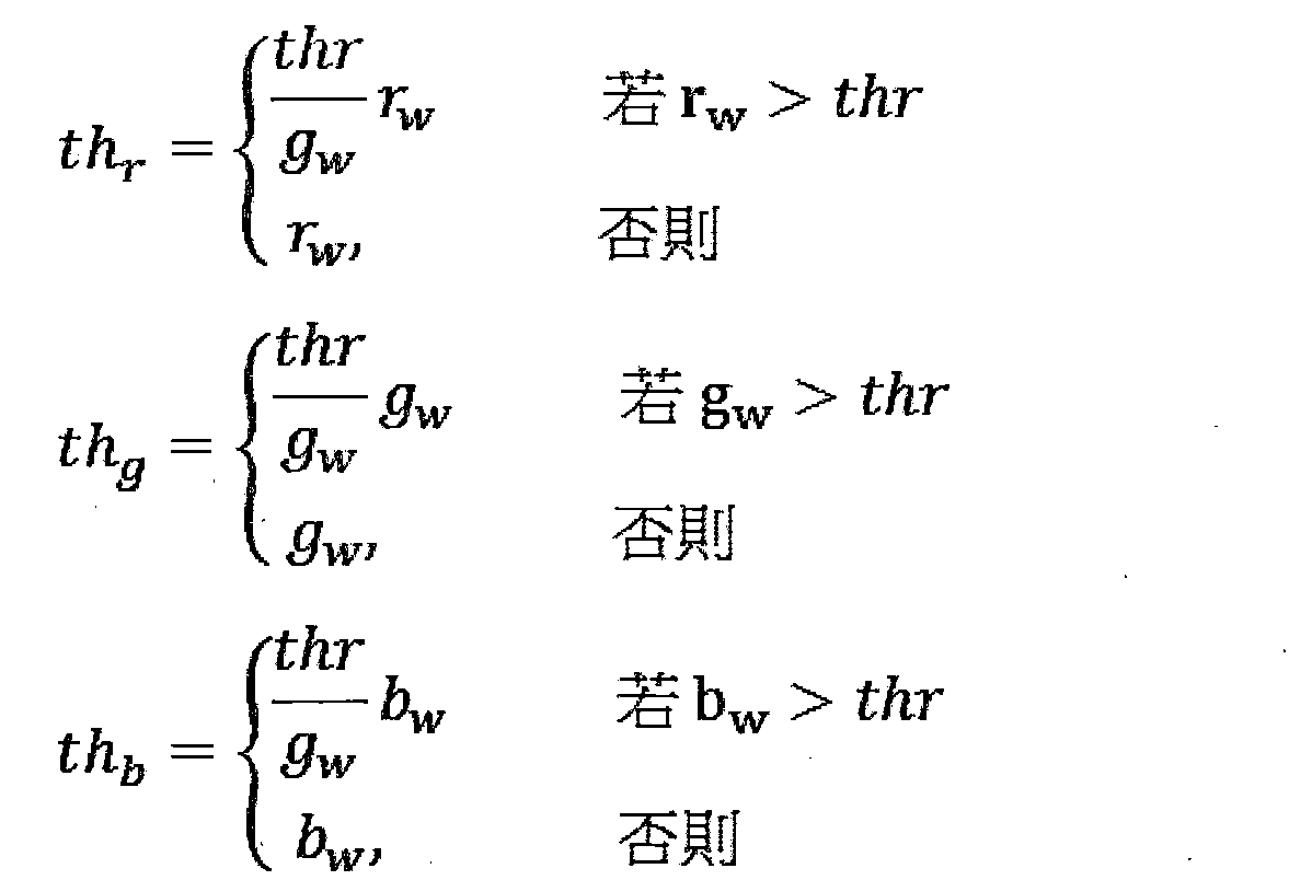
再次,若元素中的任一者r w ,g w ,b w 
方程3表示藉由照明體的所有色坐標r w ,g w ,b w 的一相同移位[thl-min( W rgb )],得到飽和色檢測所使用的臨界值th r 、th g 及th b 。 Equation 3 shows that the threshold values th r , th g, and th used in the saturated color detection are obtained by the same shift of all the color coordinates r w , g w , and b w of the illuminating body [thl -min ( W rgb )] b .
方程4表示使用高於1的位似比
在圖1所繪示的第三步驟中,將影像中飽和像素識別為具有顏色以r、g及b色坐標表示的該等像素,以使r>th r 及/或g>th g 及/或b>th b 。此等飽和像素形成影像的飽和區域。 In the third step shown in FIG. 1, the saturated pixels in the image are identified as those pixels with colors represented by the r, g, and b color coordinates, so that r > th r and/or g > th g and/ Or b > th b . These saturated pixels form the saturated area of the image.
在以上定標的一變體中,此定標係局部地執行在一知覺均勻色空間(如LCh色空間)中,並非整個執行在上述裝置依存的RGB色空間中。 In a variant of the above calibration, the calibration is performed locally in a perceptual uniform color space (such as the LCh color space), not the entire RGB color space dependent on the above device.
在此變體的第一子步中,藉由定標照明體的顏色 W rgb 以計算一中間臨界向量 th' ,以使此照明體的綠色分量g w 定標成thr如下:

較佳選擇綠色分量用於此定標子步,原因在於對照紅色分 量及藍色分量,綠色分量對影像的亮度具有最大貢獻,但亦可能使用照明體的紅色分量或藍色分量用於此定標。 It is better to choose the green component for this calibration substep because it is compared with the red component. The green component has the greatest contribution to the brightness of the image, but it is also possible to use the red component or the blue component of the illuminator for this calibration.
若中間臨界向量 th' 的色彩分量th' r 、th' g 及th' b 中的任一者超出最大位元值(在此係255),則在此等色彩分量th' r 、th' g 及th' b (表示在RGB色空間的臨界顏色)轉換成色彩分量th' L 、th' C 及th' h (表示在LCh色空間的相同顏色)後,將Chroma(色度)分量th' C 定標成一縮小值th" C =k.th' C ,以便色彩分量th' L 、th" C 及th' h 在RGB色空間中的轉換所形成的色彩分量th" r 、th" g 及th" b 中無一者超出最大位元值255,其中k係儘可能接近1且少於1。藉由迭代可找出此一k值。最終臨界顏色 th" 係由色彩分量th" r 、th" g 及th" b 表示在RGB色空間的顏色。 If any of the color components th' r , th' g, and th' b of the intermediate critical vector th' exceeds the maximum bit value (in this case 255), then the color components th' r and th' g And th' b (representing the critical color in the RGB color space) is converted into the color components th' L , th' C, and th' h (representing the same color in the LCh color space), then the Chroma (chromaticity) component th' C scaled to a reduced value th "C = k. th ' C, so that the color component of th' L, th" color component C and th 'h converted in the RGB color space formed by th "r, th" g and None of th" b exceeds the maximum bit value of 255, where k is as close to 1 as possible and less than 1. This value of k can be found by iteration. The final critical color th" is determined by the color components th" r , th" g and th" b represent the colors in the RGB color space.
因執行上述chroma(色度)定標而不變更色相,定標的此變體因此有利地確保影像的照明點的色相不變,及因此在檢測影像中飽和像素後,在飽和/修剪區修正中有利地避開任何無意的色相變更。由於調整照明點係藉由將其Chroma(色度)分量定標在CIE LCh色空間中,因此變成越來越少飽和,有利地保留其色相。 Since the above chroma (chroma) calibration is performed without changing the hue, this variant of calibration thus advantageously ensures that the hue of the illumination point of the image remains unchanged, and therefore, after detecting the saturated pixels in the image, in the saturation/trimming area correction Advantageously avoid any unintentional hue changes. Since the lighting point is adjusted by calibrating its Chroma (chromaticity) component in the CIE LCh color space, it becomes less and less saturated, which advantageously retains its hue.
以上所已說明用以檢測場景的影像中飽和像素的方法及模組有利地限制飽和像素的錯誤檢測,特別係因為此檢測考量到場景的照明體的效應。 The methods and modules described above for detecting saturated pixels in an image of a scene advantageously limit the false detection of saturated pixels, especially because the detection takes into account the effects of the illumination body of the scene.
雖然已在本文中參考附圖描述本發明的說明性實施例,但應瞭解本發明不限於該等精確實施例,不背離本發明,相關領域的普通技術人員亦可在其中實現各種變更及修改,意欲將所有此類變更及修改包括在本發明如後附申請專利範圍的範疇內。如熟諳此藝者所顯而易見的,因此如申請專利範圍所主張,本發明包括本文中所述特殊範例及較佳實施例來的變化。 Although the illustrative embodiments of the present invention have been described herein with reference to the accompanying drawings, it should be understood that the present invention is not limited to these precise embodiments, and without departing from the present invention, those of ordinary skill in the relevant fields can also implement various changes and modifications therein. It is intended to include all such changes and modifications within the scope of the present invention, such as the appended patent application. As is obvious to those who are familiar with this art, as claimed in the scope of the patent application, the present invention includes variations from the specific examples and preferred embodiments described herein.
雖然有些特定實施例係可分開地說明及主張,但當然可組合地使用在本文說明及主張的實施例的各種特徵。 Although some specific embodiments can be described and claimed separately, of course, various features of the embodiments described and claimed herein can be used in combination.
r,g,b‧‧‧影像之像素 r,g,b ‧‧‧Pixel of image
r w ,g w ,b w ‧‧‧照明體之色坐標 r w ,g w ,b w ‧‧‧Color coordinates of the illuminating body
thl,thr‧‧‧臨界強度/亮度之下限及上限 thl,thr ‧‧‧Critical intensity/lower and upper limit of brightness
th r ,th g ,th b ‧‧‧飽和臨界值 th r ,th g ,th b ‧‧‧saturation threshold
Claims (10)
Applications Claiming Priority (3)
| Application Number | Priority Date | Filing Date | Title |
|---|---|---|---|
| EP16305372.1 | 2016-03-30 | ||
| EP16305372.1A EP3226203A1 (en) | 2016-03-30 | 2016-03-30 | Method for detection of saturated pixels in an image |
| ??16305372.1 | 2016-03-30 |
Publications (2)
| Publication Number | Publication Date |
|---|---|
| TW201801042A TW201801042A (en) | 2018-01-01 |
| TWI736599B true TWI736599B (en) | 2021-08-21 |
Family
ID=55701900
Family Applications (1)
| Application Number | Title | Priority Date | Filing Date |
|---|---|---|---|
| TW106110648A TWI736599B (en) | 2016-03-30 | 2017-03-30 | Method for detection of saturated pixels in an image |
Country Status (11)
| Country | Link |
|---|---|
| US (1) | US11488289B2 (en) |
| EP (2) | EP3226203A1 (en) |
| JP (1) | JP6876068B2 (en) |
| KR (1) | KR102287127B1 (en) |
| CN (1) | CN109844803B (en) |
| BR (1) | BR112018069885A2 (en) |
| CA (1) | CA3019961C (en) |
| MX (1) | MX2018011885A (en) |
| RU (1) | RU2750088C2 (en) |
| TW (1) | TWI736599B (en) |
| WO (1) | WO2017167700A1 (en) |
Families Citing this family (4)
| Publication number | Priority date | Publication date | Assignee | Title |
|---|---|---|---|---|
| US11074677B2 (en) | 2018-03-29 | 2021-07-27 | Dolby Laboratories Licensing Corporation | Dynamic range extension of partially clipped pixels in captured images |
| US11100620B2 (en) | 2018-09-04 | 2021-08-24 | Apple Inc. | Hue preservation post processing for highlight recovery |
| EP3729801B1 (en) | 2018-12-27 | 2021-12-01 | Dolby Laboratories Licensing Corporation | Rendering wide color gamut, two-dimensional (2d) images on three-dimensional (3d) capable displays |
| EP3839876A1 (en) * | 2019-12-20 | 2021-06-23 | Fondation B-COM | Method for converting an image and corresponding device |
Citations (5)
| Publication number | Priority date | Publication date | Assignee | Title |
|---|---|---|---|---|
| US20040246336A1 (en) * | 2003-06-04 | 2004-12-09 | Model Software Corporation | Video surveillance system |
| JP2010103700A (en) * | 2008-10-22 | 2010-05-06 | Ricoh Co Ltd | Imaging device and imaging method |
| TW201242379A (en) * | 2011-02-28 | 2012-10-16 | Spatial Photonics Inc | Method for obtaining brighter images from an LED projector |
| US20140375849A1 (en) * | 2013-06-25 | 2014-12-25 | Canon Kabushiki Kaisha | Image processing apparatus, image pickup apparatus, image processing method and non-transitory computer-readable storage medium storing image processing program |
| US20150063690A1 (en) * | 2013-08-27 | 2015-03-05 | Htc Corporation | Method and device for detecting glare pixels of image |
Family Cites Families (20)
| Publication number | Priority date | Publication date | Assignee | Title |
|---|---|---|---|---|
| US5231504A (en) | 1991-12-30 | 1993-07-27 | Xerox Corporation | Method for improved color reproduction using linear mixing calculations based on positional relationships between an original color and an achromatic region in a linear mixing space |
| US20020163525A1 (en) | 2001-03-07 | 2002-11-07 | Shih-Pei Liao | Method for enhancing saturation of color images |
| CN1300744C (en) * | 2003-12-09 | 2007-02-14 | 香港中文大学 | Automatic method for modifying digital image and system of adopting the method |
| EP1747665B1 (en) * | 2004-05-11 | 2017-09-06 | Samsung Electronics Co., Ltd. | Method for processing color image data |
| JP4479457B2 (en) * | 2004-05-27 | 2010-06-09 | ソニー株式会社 | Image processing apparatus, image processing method, and computer program |
| US8331665B2 (en) | 2004-12-01 | 2012-12-11 | Tp Vision Holding B.V. | Method of electronic color image saturation processing |
| US20060146193A1 (en) | 2004-12-30 | 2006-07-06 | Chaminda Weerasinghe | Method and system for variable color saturation |
| JP2006303559A (en) | 2005-04-15 | 2006-11-02 | Matsushita Electric Ind Co Ltd | Electronic camera |
| JP2006333313A (en) | 2005-05-30 | 2006-12-07 | Seiko Epson Corp | Image correction device, method, and program |
| US7893975B2 (en) * | 2006-10-13 | 2011-02-22 | Apple Inc. | System and method for processing images using predetermined tone reproduction curves |
| JP5004305B2 (en) | 2008-09-04 | 2012-08-22 | 株式会社リコー | Image processing apparatus, image processing method, program, and recording medium |
| JP5177751B2 (en) | 2008-09-29 | 2013-04-10 | ルネサスエレクトロニクス株式会社 | Display drive circuit |
| JP5223686B2 (en) | 2009-01-07 | 2013-06-26 | 株式会社リコー | Imaging apparatus and imaging method |
| KR20120091578A (en) * | 2011-02-09 | 2012-08-20 | 삼성전자주식회사 | Method and apparatus for changing of brightness of an image |
| US9171215B2 (en) | 2012-01-17 | 2015-10-27 | Honda Motor Co., Ltd. | Image processing device |
| JP2015092643A (en) | 2012-01-30 | 2015-05-14 | 日本電気株式会社 | Image processing device, image processing method thereof, computer program and image processing system |
| JP2015092301A (en) | 2012-01-30 | 2015-05-14 | 日本電気株式会社 | Image processing apparatus and image processing method of the same, and computer program and image processing system |
| WO2015113655A1 (en) | 2014-01-31 | 2015-08-06 | Thomson Licensing | Method for conversion of a saturated image into a non-saturated image |
| US9749534B2 (en) * | 2014-12-31 | 2017-08-29 | Canon Kabushiki Kaisha | Devices, systems, and methods for estimation of motion blur from a single image |
| US9336582B1 (en) * | 2015-04-17 | 2016-05-10 | Google Inc. | Convolutional color correction |
-
2016
- 2016-03-30 EP EP16305372.1A patent/EP3226203A1/en not_active Withdrawn
-
2017
- 2017-03-27 CN CN201780021645.5A patent/CN109844803B/en active Active
- 2017-03-27 KR KR1020187028205A patent/KR102287127B1/en active IP Right Grant
- 2017-03-27 MX MX2018011885A patent/MX2018011885A/en unknown
- 2017-03-27 WO PCT/EP2017/057222 patent/WO2017167700A1/en active Application Filing
- 2017-03-27 US US16/090,262 patent/US11488289B2/en active Active
- 2017-03-27 JP JP2018551371A patent/JP6876068B2/en active Active
- 2017-03-27 RU RU2018138020A patent/RU2750088C2/en active
- 2017-03-27 BR BR112018069885A patent/BR112018069885A2/en unknown
- 2017-03-27 EP EP17712528.3A patent/EP3437066B1/en active Active
- 2017-03-27 CA CA3019961A patent/CA3019961C/en active Active
- 2017-03-30 TW TW106110648A patent/TWI736599B/en active
Patent Citations (5)
| Publication number | Priority date | Publication date | Assignee | Title |
|---|---|---|---|---|
| US20040246336A1 (en) * | 2003-06-04 | 2004-12-09 | Model Software Corporation | Video surveillance system |
| JP2010103700A (en) * | 2008-10-22 | 2010-05-06 | Ricoh Co Ltd | Imaging device and imaging method |
| TW201242379A (en) * | 2011-02-28 | 2012-10-16 | Spatial Photonics Inc | Method for obtaining brighter images from an LED projector |
| US20140375849A1 (en) * | 2013-06-25 | 2014-12-25 | Canon Kabushiki Kaisha | Image processing apparatus, image pickup apparatus, image processing method and non-transitory computer-readable storage medium storing image processing program |
| US20150063690A1 (en) * | 2013-08-27 | 2015-03-05 | Htc Corporation | Method and device for detecting glare pixels of image |
Also Published As
| Publication number | Publication date |
|---|---|
| CA3019961C (en) | 2024-02-27 |
| CA3019961A1 (en) | 2017-10-05 |
| RU2750088C2 (en) | 2021-06-22 |
| CN109844803B (en) | 2023-07-07 |
| KR20190038753A (en) | 2019-04-09 |
| RU2018138020A (en) | 2020-04-30 |
| RU2018138020A3 (en) | 2020-08-19 |
| BR112018069885A2 (en) | 2019-02-05 |
| EP3226203A1 (en) | 2017-10-04 |
| MX2018011885A (en) | 2019-06-06 |
| US11488289B2 (en) | 2022-11-01 |
| EP3437066B1 (en) | 2021-03-17 |
| WO2017167700A1 (en) | 2017-10-05 |
| EP3437066A1 (en) | 2019-02-06 |
| KR102287127B1 (en) | 2021-08-05 |
| TW201801042A (en) | 2018-01-01 |
| JP6876068B2 (en) | 2021-05-26 |
| JP2019513335A (en) | 2019-05-23 |
| CN109844803A (en) | 2019-06-04 |
| US20190114749A1 (en) | 2019-04-18 |
Similar Documents
| Publication | Publication Date | Title |
|---|---|---|
| US10397486B2 (en) | Image capture apparatus and method executed by image capture apparatus | |
| US8941755B2 (en) | Image processing device with automatic white balance | |
| TWI736599B (en) | Method for detection of saturated pixels in an image | |
| TWI399100B (en) | Image processing method | |
| WO2018176925A1 (en) | Hdr image generation method and apparatus | |
| US8698918B2 (en) | Automatic white balancing for photography | |
| US9699386B2 (en) | Image processing apparatus and method | |
| US20140125836A1 (en) | Robust selection and weighting for gray patch automatic white balancing | |
| WO2021218603A1 (en) | Image processing method and projection system | |
| US11889202B2 (en) | Image processing apparatus, image processing method, and storage medium | |
| US10630954B2 (en) | Estimation of illumination chromaticity in automatic white balancing | |
| JP6904788B2 (en) | Image processing equipment, image processing methods, and programs | |
| CN114143443B (en) | Dual-sensor imaging system and imaging method thereof | |
| CN115514947B (en) | Algorithm for automatic white balance of AI (automatic input/output) and electronic equipment | |
| Jo et al. | Adaptive white point extraction based on dark channel prior for automatic white balance | |
| US10393992B1 (en) | Auto focus based auto white balance | |
| US20120121171A1 (en) | Method and apparatus for determining a value of an attribute to be associated with an image | |
| Lee et al. | Auto White Balance Using Chromatic Coordinates of Detected Human Faces | |
| JP2011182147A (en) | Photographing scene determining device |