RU29363U1 - Thermal curtain - Google Patents
Thermal curtain Download PDFInfo
- Publication number
- RU29363U1 RU29363U1 RU2002135438/20U RU2002135438U RU29363U1 RU 29363 U1 RU29363 U1 RU 29363U1 RU 2002135438/20 U RU2002135438/20 U RU 2002135438/20U RU 2002135438 U RU2002135438 U RU 2002135438U RU 29363 U1 RU29363 U1 RU 29363U1
- Authority
- RU
- Russia
- Prior art keywords
- heaters
- thermal curtain
- reflector
- supports
- thermal
- Prior art date
Links
Landscapes
- Curtains And Furnishings For Windows Or Doors (AREA)
Description
Тепловая завесаThermal curtain
Полезная модель относится к устройствам для создания вертикального (сверху вниз) воздушного заслона в дверном проёме для поддержания внутреннего комфорта в защищаемом помещении.The invention relates to devices for creating a vertical (top to bottom) air screen in a doorway to maintain internal comfort in a protected room.
Известна тепловая завеса (патент РФ №2122686, МПК F 24 F 9/00, опубл. в бюл. 33/98г.), содержащая корпус, колесо рабочее, нагреватели, решётку, направляющее устройство, элемент коммутации, язык, отделяющий входной коллектор от выходного.Known thermal curtain (RF patent No. 2122686, IPC F 24 F 9/00, published in bull. 33 / 98g.), Comprising a housing, impeller, heaters, grill, guide device, switching element, language that separates the input collector from day off.
Недостатком этой тепловой завесы является сложность монтажных и ремонтных работ.The disadvantage of this thermal curtain is the complexity of installation and repair work.
Известна также наиболее близкая по технической сущности к предложенной тепловая завеса (рекламный каталог фирмы «PYROX «Вентиляционное и отопительное оборудование, стр. 36, 37), содержащая корпус с жестко закреплёнными на нём опорами, переднюю и боковые крышки, рассекатель, отражатель, колесо рабочее, нагреватели, термовыключатель, установленные между опорами, решетку, переключатель режимов работы, электродвигатель.Also known is the closest in technical essence to the proposed thermal curtain (advertising catalog of the company “PYROX“ Ventilation and heating equipment, p. 36, 37), containing a housing with fixed supports on it, front and side covers, a divider, a reflector, an impeller , heaters, a thermal switch installed between the supports, a grill, an operating mode switch, an electric motor.
Недостатком известной тепловой завесы является достаточно высокая стоимость в результате использования при изготовлении дорогостоящего специнструмента и оборудования.A disadvantage of the known thermal curtain is a rather high cost as a result of using expensive special tools and equipment in the manufacture.
Техническим результатом полезной модели является снижение материалоемкости и себестоимости.The technical result of the utility model is to reduce material consumption and cost.
Технический результат достигается тем, что известная тепловая завеса, содержащая корпус с жёстко закрепленными на нем опорами, переднюю и боковые крышки, рассекатель, отражатель, колесо рабочее, нагреватели, термовыключатель, установленные между опорами, решётку, переключатель режимов работы, электродвигатель, дополнительно снабжена термостатом, а упомянутый отражатель выполнен сложной конфигурации из листового материала, повторяющим форму улитки, переключатель режимов работы выполнен кулачковым, совмещающим управление функционированием рабочего колеса и нагревателей.The technical result is achieved by the fact that the well-known thermal curtain, comprising a housing with rigidly fixed supports on it, front and side covers, a divider, a reflector, an impeller, heaters, a thermal switch installed between the supports, a grill, an operating mode switch, an electric motor, is additionally equipped with a thermostat and the aforementioned reflector is made of a complex configuration of sheet material repeating the shape of a cochlea, the operating mode switch is made cam-type, combining functional control aniem impeller and heaters.
Сущность полезной модели заключается в том, что тепловая завеса дополнительно содержит термостат, а отражатель выполнен сложной конфигурации из листового материала, повторяющим форму улитки, переключатель режимов работы выполнен кулачковым, совмещающим управление функционированием рабочего колеса и нагревателей, что позволило снизить материалоемкость и себестоимость изготовления.The essence of the utility model lies in the fact that the thermal curtain additionally contains a thermostat, and the reflector is made of a complex configuration of sheet material, repeating the shape of a cochlea, the operating mode switch is made cam, combining the control of the functioning of the impeller and heaters, which allowed to reduce material consumption and manufacturing costs.
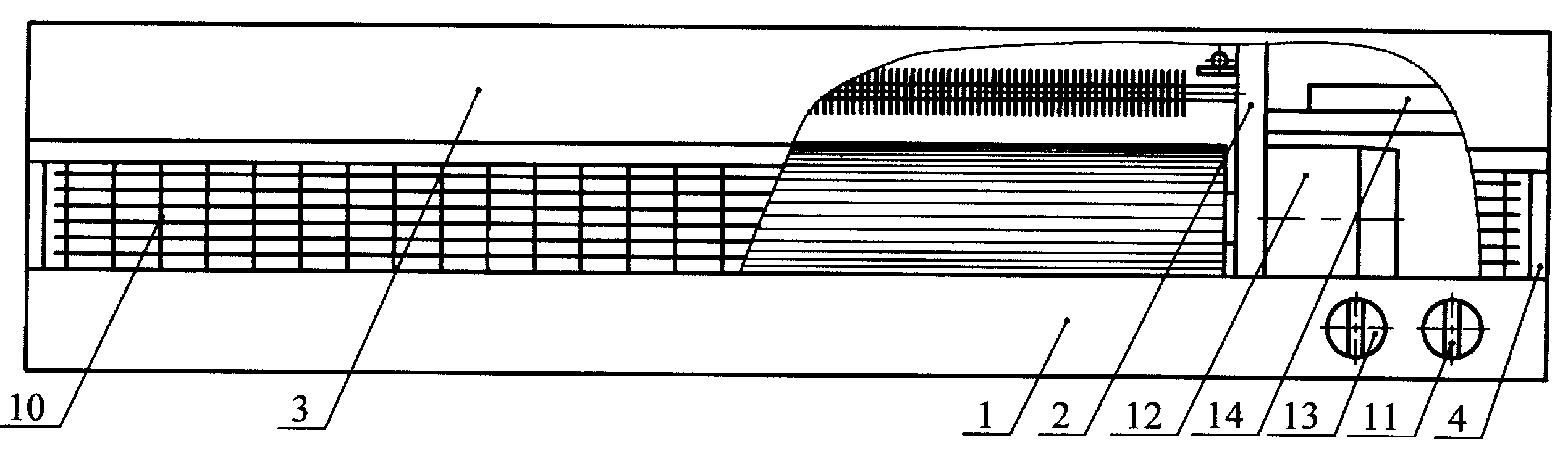
На фиг. 1 изображена тепловая завеса, продольный разрез, на фиг. 2поперечный разрез.In FIG. 1 shows a thermal curtain, a longitudinal section, in FIG. 2 cross section.
Предлагаемая тепловая завеса содержит корпус 1 коробчатой формы, в котором расположены жестко закрепленные опоры 2- правая и левая. Между опорами расположено колесо рабочее 7, один конец которогоThe proposed thermal curtain contains a box-shaped body 1, in which are rigidly mounted supports 2 - right and left. Between the supports there is a working wheel 7, one end of which
крепится к левой опоре, а другой одет на вал электродвигателя 12, который в свою очередь крепится к правой опоре и расположен в зоне расположения элементов коммутации и управления 14, рассекатель 5, отражатель 6, и нагреватели 8. Между стенкой корпуса 1 и нагревателем 8 расположен термовыключатель 9. К корпусу 1 снаружи закрепленыпереключатель режимов работы 11 и термостат 13, датчик которого расположен между опорами 2 вблизи правой опоры. Слева и справа корпус 1 закрывается боковыми крышками 4. С лицевой стороны корпус 1 закрывается передней крышкой 3. В нижней части тепловой завесы установлена решетка 10, расположенная вровень с нижней плоскостью корпуса 1.is attached to the left support, and the other is dressed on the shaft of the electric motor 12, which in turn is attached to the right support and is located in the zone of arrangement of the switching and control elements 14, a divider 5, a reflector 6, and heaters 8. Between the wall of the housing 1 and the heater 8 is located temperature switch 9. An operating mode switch 11 and a thermostat 13, the sensor of which is located between the supports 2 near the right support, are fixed to the housing 1 from the outside. On the left and right, the housing 1 is closed by the side covers 4. On the front side, the housing 1 is closed by the front cover 3. A grill 10 is installed at the bottom of the heat curtain, which is flush with the lower plane of the housing 1.
Тепловая завеса работает следующим образом. Воздух под напором колеса рабочего 7 поступает на обдув нагревателей 8. Нагретый воздух проходит по профилю отражателя 6, и через решетку 10 отводится потребителю.The thermal curtain works as follows. Air under the pressure of the working wheel 7 is supplied to blow heaters 8. Heated air passes along the profile of the reflector 6, and is discharged through the grill 10 to the consumer.
Claims (1)
Priority Applications (1)
| Application Number | Priority Date | Filing Date | Title |
|---|---|---|---|
| RU2002135438/20U RU29363U1 (en) | 2002-12-30 | 2002-12-30 | Thermal curtain |
Applications Claiming Priority (1)
| Application Number | Priority Date | Filing Date | Title |
|---|---|---|---|
| RU2002135438/20U RU29363U1 (en) | 2002-12-30 | 2002-12-30 | Thermal curtain |
Publications (1)
| Publication Number | Publication Date |
|---|---|
| RU29363U1 true RU29363U1 (en) | 2003-05-10 |
Family
ID=35869912
Family Applications (1)
| Application Number | Title | Priority Date | Filing Date |
|---|---|---|---|
| RU2002135438/20U RU29363U1 (en) | 2002-12-30 | 2002-12-30 | Thermal curtain |
Country Status (1)
| Country | Link |
|---|---|
| RU (1) | RU29363U1 (en) |
Cited By (1)
| Publication number | Priority date | Publication date | Assignee | Title |
|---|---|---|---|---|
| RU189526U1 (en) * | 2018-12-20 | 2019-05-24 | Алексей Вячеславович Пухов | AIR CURTAIN |
-
2002
- 2002-12-30 RU RU2002135438/20U patent/RU29363U1/en not_active IP Right Cessation
Cited By (1)
| Publication number | Priority date | Publication date | Assignee | Title |
|---|---|---|---|---|
| RU189526U1 (en) * | 2018-12-20 | 2019-05-24 | Алексей Вячеславович Пухов | AIR CURTAIN |
Similar Documents
| Publication | Publication Date | Title |
|---|---|---|
| US11499749B2 (en) | Heating blower and heating device | |
| US20080098759A1 (en) | Dualpower temperature regulation system | |
| CN102322428A (en) | Tower fan for blowing and heating | |
| CN106196238B (en) | A kind of color temperature-tunable energy-saving bathroom heater | |
| KR102421171B1 (en) | Multifunctional body dryer for bathroom | |
| NL2000708C1 (en) | INFRARED FLOODLIGHT. | |
| JP6899089B2 (en) | Sanitary cleaning equipment | |
| WO2007042894A1 (en) | Ventilation device combinable to a natural convection radiator in a heating and/or cooling system | |
| CN215260554U (en) | a heater | |
| CN212746662U (en) | Air outlet structure and household appliance | |
| CN205191710U (en) | Carbon fiber heater | |
| CN210532533U (en) | Sweep wind mechanism and air conditioner | |
| CN2177185Y (en) | Filling oil hot wind type electric heater | |
| RU23097U1 (en) | ELECTRIC FAN | |
| JP6476409B2 (en) | Ventilation equipment | |
| CN206582154U (en) | A kind of hot fan | |
| CN202215492U (en) | A tower fan for both blowing and heating | |
| RU21086U1 (en) | FAN HEATER | |
| CN223331807U (en) | A tower heater | |
| KR200494377Y1 (en) | A warm air circulator for agricultural purpose | |
| KR200262619Y1 (en) | Electric heater | |
| CN222824447U (en) | A cooling and heating circulation fan with built-in heating component | |
| CN223974380U (en) | Clothes airing machine | |
| CN214039570U (en) | Vacuum furnace door motor opening device | |
| US3109421A (en) | Radiant heat control shield |
Legal Events
| Date | Code | Title | Description |
|---|---|---|---|
| MM1K | Utility model has become invalid (non-payment of fees) |
Effective date: 20041231 |