RU2705421C1 - Method of transmitting data over a bus, a communication system for realizing said method and an automatic protection device for preventing an emergency situation at a control object - Google Patents
Method of transmitting data over a bus, a communication system for realizing said method and an automatic protection device for preventing an emergency situation at a control object Download PDFInfo
- Publication number
- RU2705421C1 RU2705421C1 RU2018146099A RU2018146099A RU2705421C1 RU 2705421 C1 RU2705421 C1 RU 2705421C1 RU 2018146099 A RU2018146099 A RU 2018146099A RU 2018146099 A RU2018146099 A RU 2018146099A RU 2705421 C1 RU2705421 C1 RU 2705421C1
- Authority
- RU
- Russia
- Prior art keywords
- data
- controller
- bus
- local memory
- mode
- Prior art date
Links
Images


Abstract
Description
Изобретения относятся к области сетей связи, а именно к интерфейсу TSI, предназначенному для последовательной передачи данных по шине. В частности, в заявке описан протокол TSI, система связи, предназначенная для реализации данного протокола, и устройство противоаварийной автоматической защиты, в котором использованы система связи и способ передачи данных.The invention relates to the field of communication networks, namely to the TSI interface, designed for serial data transmission over the bus. In particular, the application describes the TSI protocol, a communication system designed to implement this protocol, and an emergency emergency protection device that uses a communication system and data transmission method.
В заявке описан периферийный интерфейсный сложно-функциональный блок (далее СФ-блок), разработанный для СБИС типа «система на кристалле» (далее СнК).The application describes a peripheral interface complex functional block (hereinafter referred to as SF block) developed for VLSIs of the “system on a chip” type (hereinafter referred to as SNK).
В ходе работ по разработке СнК класса микропроцессоров или микроконтроллеров для применения в составе промышленных контроллеров, терминалах релейной защиты и автоматики (РЗА) и автоматизированных системах управления технологическими процессами (АСУ ТП) был разработан СФ-блок "TSI_controller", предназначенный для программной и аппаратной реализации протокола. С помощью СФ-блока "TSI_controller" осуществляется обмен данными по шине с внешними по отношению к СнК устройствами, имеющими такой же СФ-блок. Описанный в заявке СФ-блок в зависимости от области применения поддерживает один из двух протоколов. Первый протокол ТМВ5000 описан в заявке на изобретение ЕА №201700029 А1, опубликованной 28.02.2018 г. и в заявке на изобретение RU №2018111465, поданной 30.03.2018 г. Второй протокол TSI описан в данной заявке.During the development of the SoC class of microprocessors or microcontrollers for use in industrial controllers, relay protection and automation terminals (RPA) and automated process control systems (APCS), the TSI_controller SF block was developed for software and hardware implementation protocol. Using the TSI_controller SF block, data is exchanged on the bus with devices external to the SoC that have the same SF block. The SF block described in the application, depending on the field of application, supports one of two protocols. The first TMV5000 protocol is described in the application for invention EA No. 201700029 A1, published on 02.28.2018 and in the application for invention RU No.2018111465, filed on 03.30.2018. The second TSI protocol is described in this application.
СнК с заявляемым СФ-блоком изготовлена по КМОП-технологии 28 нм.SoK with the claimed SF block is made according to the CMOS technology of 28 nm.
При описании СФ-блока и протокола используемые термины имеют следующее значение:When describing the SF block and protocol, the terms used have the following meanings:
«Протокол обмена данными» или «протокол передачи данных» - набор правил и соглашений, определяющих содержимое, формат, параметры времени, последовательность и проверку ошибок в пакетах данных, которыми обмениваются модули устройства.A “data exchange protocol” or “data transfer protocol” is a set of rules and conventions that define the content, format, time parameters, sequence and error checking in data packets exchanged between device modules.
«Ведущее устройство (Master)» - устройство, которое посылает данные другим устройствам и/или запрашивает данные от других устройств, т.е. является инициатором в обмене данными с ведомым устройством.“Master” means a device that sends data to other devices and / or requests data from other devices, i.e. is the initiator in the exchange of data with the slave device.
«Ведомое устройство (Slave)» - устройство, которое может обмениваться информацией только с ведущим устройством после того, как от ведущего устройства поступит соответствующий запрос.“Slave device” means a device that can exchange information only with the master device after a corresponding request is received from the master device.
«Шина» - дифференциальная витая пара проводов или дифференциальная пара проводников на печатной плате, по которой осуществляют передачу данных в виде электрических сигналов от отправителя к получателю."Bus" - a differential twisted pair of wires or a differential pair of conductors on a printed circuit board, which transmit data in the form of electrical signals from the sender to the receiver.
«Общая шина» или «магистраль» - тип линии связи, при котором все модули устройства подсоединены к общей линии связи. Общая линия связи используется всеми модулями по очереди. Все сообщения, посылаемые отдельными модулями, прослушиваются всеми остальными модулями, подключенными к линии связи, но из потока сообщений модуль отбирает только адресованные ему сообщения.“Shared bus” or “trunk” is a type of communication line in which all modules of the device are connected to a common communication line. A common communication line is used by all modules in turn. All messages sent by individual modules are listened to by all other modules connected to the communication line, but the module selects only messages addressed to it from the message flow.
«Слово» - строка битов, рассматриваемая как единое целое при их передаче, приеме, коммутации, обработке, отображении и хранении."Word" - a string of bits, considered as a single unit during their transmission, reception, switching, processing, display and storage.
«Пакет» - блок данных, обрабатываемый сетевыми программами как единое целое.A “packet” is a data block processed by network programs as a whole.
«Контрольный пакет» - пакет данных, выполняющих роль служебной информации, необходимых для реализации протокола.“Control packet” - a packet of data that plays the role of service information necessary for the implementation of the protocol.
«Информационный пакет» - пакет, состоящих из служебных данных и полезных данных, которые должны быть переданы.“Information packet” - a packet consisting of service data and useful data that must be transmitted.
Общая структура контрольного или информационного пакета определяется составом пакета и его форматом.The general structure of a control or information package is determined by the composition of the package and its format.
«Состав» - содержащиеся в пакете различные типы данных.“Composition” - various data types contained in a package.
«Поле» - определенный тип данных, при этом размер этих данных в битах это длина поля.“Field” is a specific data type, and the size of this data in bits is the length of the field.
«Формат» - размер и порядок размещения различных типов данных."Format" - the size and placement of various types of data.
«Сообщение» или «транзакция» - последовательность передаваемых контрольного и информационного пакетов, которая представляет собой законченную операцию работы с данными, например операцию «чтение» или операцию «запись» данных.“Message” or “transaction” is a sequence of transmitted control and information packets, which is a completed operation of working with data, for example, a “read” operation or a “write” operation of data.
«Технологический объект управления» - объект управления, включающий технологическое оборудование и реализуемый в нем технологический процесс.“Technological control object” - a control object that includes technological equipment and the technological process implemented in it.
Известен интерфейс, описанный в стандарте MIL-STD-1553В, dated 21 September 1978, «Department of defense interface standard for digital time division command/response multiplex data bus» (обозначение военного стандарта США). В нашей стране он был утвержден как ГОСТ 26765.52-87, который заменен на ГОСТ Р 52070-2003 «Интерфейс магистральный последовательный системы электронных модулей. Общие требования». Данный стандарт описывает магистральный последовательный интерфейс с централизованным управлением, применяемый в системе электронных модулей, и устанавливает требования к организации обмена информацией, функциям устройств интерфейса и контролю передачи информации, характеристикам информационной магистрали и характеристикам устройств интерфейса. Интерфейс функционирует асинхронно в режиме «команда-ответ». Инициирование обмена информацией и управление передачей осуществляет только контроллер шины, подключенный к шине типа «магистраль». К этой же шине подключены удаленные терминалы, функционирующие в соответствии с командами контроллера шины, и монитор, осуществляющий отбор информации, передаваемой по шине. Стандартом определен состав слов - командное слово, слово данных и ответное слово. Размер каждого слова равен 20 разрядам. Слова начинаются с синхросигнала (три разряда), затем следуют 16 информационных разрядов и разряд контроля по четности (Р). Вся информация на магистрали передается в коде «Манчестер-2». Командное слово содержит поле «адрес оконечного устройства» и разряд «прием/передача». Дополнительно командное слово содержит поле «подадрес оконечного устройства» и поле «число слов данных» или поле «код признака режима управления» и поле «код команды управления». В случае если командное слово содержит поле «код режима управления» и поле «код команды управления», его называют командой управления. Команда управления применяется только для управления устройствами интерфейса, но не для обмена данными с абонентами интерфейса. Команда управления следует применять без слов данных или с одним словом данных. Ответное слово содержит адрес оконечного устройства и диагностические данные (поле разрядов признаков состояния оконечного устройства или признаков достоверности принятого командного слова). Их значение дает следующую информацию: ошибка в сообщении, передача ответного слова, запрос на обслуживание, резервные разряды, принята групповая команда, абонент занят, неисправность абонента, принято управление интерфейсом, неисправность оконечного устройства и три резервных разряда. Интерфейс имеет следующие недостатки. Максимальный размер сообщения, которое может быть передано или принято не более 32 слов данных. Не обеспечен полный контроль достоверности передаваемой информации. Адресуемых абонентов не более 31.The known interface described in the standard MIL-STD-1553B, dated 21 September 1978, "Department of defense interface standard for digital time division command / response multiplex data bus" (designation of the US military standard). In our country, it was approved as GOST 26765.52-87, which is replaced by GOST R 52070-2003 “Serial trunk system interface of electronic modules. General requirements". This standard describes a serial main interface with centralized control used in the electronic module system and establishes requirements for the organization of information exchange, the functions of interface devices and the control of information transfer, the characteristics of the information highway and the characteristics of interface devices. The interface operates asynchronously in command-response mode. Initiation of information exchange and transmission control is carried out only by the bus controller connected to the bus type "trunk". Remote terminals operating in accordance with the commands of the bus controller and a monitor that selects information transmitted via the bus are connected to the same bus. The standard defines the composition of words - command word, data word and response word. The size of each word is 20 digits. Words begin with a clock signal (three digits), then 16 information bits and a parity check bit (P) follow. All information on the highway is transmitted in the Manchester-2 code. The control word contains the field "address of the terminal device" and the category "receive / transmit". Additionally, the command word contains a field “terminal address of the terminal device” and a field “number of data words” or a field “control mode attribute code” and a “control command code” field. If the control word contains the field "control mode code" and the field "control command code", it is called a control command. The control command is used only for managing interface devices, but not for exchanging data with interface users. The control command should be applied without data words or with one data word. The response word contains the address of the terminal device and diagnostic data (field of bits of signs of the status of the terminal device or signs of reliability of the received command word). Their value gives the following information: error in the message, transmission of the response word, service request, standby bits, group command received, subscriber busy, subscriber malfunction, interface control accepted, terminal device malfunction and three standby discharges. The interface has the following disadvantages. The maximum message size that can be transmitted or received is no more than 32 data words. Full control of the reliability of the transmitted information is not provided. Addressed subscribers no more than 31.
Известно «Интерфейсное устройство MIL-STD-1553, работающее автономно во всех трех режимах» (патент US 5,490,254 А). Целью известного изобретения являлось создание единственной интегральной схемы (далее ИС), которая бы реализовала функции всех трех устройств, определенных стандартом MIL-STD-1553В, а именно функции контроллера шины, удаленного терминала и монитора. ИС соединена с системным хост-процессором и имеет с ним общую оперативную память.Known "Interface device MIL-STD-1553, working autonomously in all three modes" (US patent 5,490,254 A). The aim of the known invention was to create a single integrated circuit (hereinafter referred to as IC), which would implement the functions of all three devices defined by the MIL-STD-1553B standard, namely the functions of a bus controller, remote terminal and monitor. The IC is connected to the system host processor and has a common RAM with it.
Наиболее близким аналогом для заявляемого способа передачи данных по шине является заявка ЕА 201700029 А1, «Способ адаптивной передачи данных в промышленном контроллере». Известный способ передачи данных заключается в том, что между ведущим устройством и ведомыми устройствами, подсоединенными к общей шине типа «магистраль», осуществляют последовательный обмен данными. Всю информацию по шине передают в коде «Манчестер-2». Последовательную передачу данных между ведущим электронным устройством и ведомым электронным устройством осуществляют в виде контрольного пакета или информационного пакета, состоящего из контрольного пакета и пакета данных. Пакет данных (полезных данных) состоит из одного или более 16 битных слов данных и 16 битного слова контрольной суммы. Каждое слово в пакете данных начинается синхросигналом (3 бита) и завершается битом контроля по четности (Р). Контрольный пакет (служебные данные) состоит из двух 16 битных управляющих слов и 16 битного слова контрольной суммы. Каждое слово в контрольном пакете начинается синхросигналом и завершается битом контроля по четности (Р). Синхросигнал предназначен для возможности отличия слов данных и слов с контрольной суммой от управляющих слов. В состав управляющих слов входят адрес запрашиваемого ведомого устройства, номер внутреннего адресного пространства запрашиваемого ведомого устройства, бит инициатора текущей передачи, бит операции запись/чтение, бит признака адаптивного чтения полезной информации, бит подтверждения достоверности принятого информационного пакета, поле со значением равным количеству слов в поле данных. Количество устройств, подсоединенных к шине, может достигать 128. Достоверность передаваемых пакетов обеспечивает проверка бита контроля по четности (Р) каждого слова и проверка контрольных сумм (CRC-16) передаваемых пакетов. В контрольном пакете содержится 6 зарезервированных бит, которые дают возможность расширить известный протокол дополнительными признаками.The closest analogue to the proposed method for transmitting data on the bus is the application EA 201700029 A1, "Adaptive data transfer method in an industrial controller." A known method of data transmission is that between the master device and slave devices connected to a common bus type "trunk", carry out a serial data exchange. All information on the bus is transmitted in the Manchester-2 code. Serial data transfer between the master electronic device and the slave electronic device is carried out in the form of a control packet or an information packet consisting of a control packet and a data packet. A data packet (payload) consists of one or more 16 bit data words and a 16 bit checksum word. Each word in the data packet begins with a clock signal (3 bits) and ends with a parity bit (P). The control packet (service data) consists of two 16-bit control words and a 16-bit checksum word. Each word in the control packet starts with a clock signal and ends with a parity bit (P). The sync signal is designed to distinguish data words and checksum words from control words. The control words include the address of the requested slave device, the number of the internal address space of the requested slave device, the bit of the initiator of the current transmission, the bit of the write / read operation, the bit of the adaptive read useful information flag, the bit of validation of the received information packet, a field with a value equal to the number of words in data field. The number of devices connected to the bus can reach 128. The reliability of the transmitted packets is ensured by checking the parity bit (P) of each word and checking the checksums (CRC-16) of the transmitted packets. The control packet contains 6 reserved bits, which make it possible to expand the known protocol with additional features.
Общим недостатком описанных выше протоколов и интерфейсного устройства является то, что они рассчитаны на использование в устройстве, работающем в нормальном (штатном) режиме. Описанные протоколы и интерфейсное устройство не описывают дополнительных средств или свойств, которые бы могли придать устройству, в котором они использованы, дополнительные возможности для реализации своего назначения при нештатной работе устройства, вызванной отказом его функциональных блоков.A common drawback of the protocols and interface devices described above is that they are designed for use in a device operating in normal (normal) mode. The described protocols and the interface device do not describe additional means or properties that could give the device in which they are used, additional opportunities for the implementation of its purpose during abnormal operation of the device caused by a failure of its functional units.
Назначением систем противоаварийной автоматической защиты (далее систем ПАЗ) является перевод объекта управления, авария на котором может привести к травмированию или смерти людей, разрушению объекта управления или нанести вред окружающей среде, в безопасное состояние, при выходе его технологических параметров за предельно допустимые значения. Устройства систем ПАЗ должны не только контролировать технологические параметры важные для безопасного состояния объекта управления, но и должно диагностировать безопасность собственной работы. В случае выхода измеряемых параметров за допустимые значения или при диагностировании устройством ПАЗ собственной небезопасной работы, система ПАЗ останавливает исполнительные устройства объекта управления.The purpose of automatic emergency protection systems (hereinafter referred to as PAZ systems) is to transfer the control facility, an accident which can lead to personal injury or death, destruction of the control facility or harm the environment, to a safe state when its technological parameters exceed the maximum permissible values. PAZ systems devices must not only control the technological parameters important for the safe state of the control object, but also must diagnose the safety of their own work. If the measured parameters go beyond the permissible values or when the PAZ device diagnoses its own unsafe operation, the PAZ system stops the actuators of the control object.
В реальности, чтобы избежать простоев объекта управления, которые приходится останавливать из-за небезопасной работы устройства системы ПАЗ, системы ПАЗ проектируются с резервированием их устройств. Такие системы называют отказоустойчивыми и позволяют продолжать технологический процесс на объекте управления.In reality, in order to avoid downtime of the control object that has to be stopped due to the unsafe operation of the PAZ system device, PAZ systems are designed with redundancy of their devices. Such systems are called fault tolerant and allow you to continue the process at the control object.
Наиболее близким аналогом для системы связи для передачи данных по шине является патент DE 19742716 А1, «Система управления и передачи данных и способ передачи данных, связанных с безопасностью». Известные изобретения относятся к области автоматизации (станки, роботы) и направлены на диагностику безопасной работы системы связи. К шине Interbus подключен модуль управления и модули ввода-вывода. Для этого в модуле управления и в модулях ввода-вывода помимо устройства, предназначенного для подключения к шине, расположены схемы безопасности. В модуле ввода-вывода в схеме безопасности расположен защитный компонент, в котором реализован протокол безопасности и который выполняет регулярное самотестирование. Данные, связанные с процессом, передаются в модуль управления в избыточном и при этом различном виде: один раз в неизмененной форме, второй раз в отрицательной форме и в третий раз в виде контрольной суммы, полученной из данных процесса. Для этого в пакете данных предусмотрены соответствующие поля. При диагностировании отказа, станок и робот могут быть отделены от системы управления с помощью переключателей, расположенных на выходной линии схемы безопасности блока ввода-вывода. Управление переключателями осуществляет защитный компонент по управляющей информации из модуля управления.The closest analogue to a communication system for transmitting data on a bus is DE 19742716 A1, “Control and data transmission system and security-related data transmission method”. Known inventions relate to the field of automation (machines, robots) and are aimed at diagnosing the safe operation of a communication system. The control module and I / O modules are connected to the Interbus bus. For this, in the control module and in the input / output modules, in addition to the device intended for connection to the bus, there are safety circuits. In the I / O module in the security circuit there is a protective component in which the security protocol is implemented and which performs a regular self-test. The data associated with the process is transferred to the control module in a redundant and at the same time different form: once in unchanged form, second time in negative form and third time in the form of a checksum obtained from the process data. For this, the corresponding fields are provided in the data packet. When diagnosing a failure, the machine and the robot can be separated from the control system using switches located on the output line of the safety circuit of the I / O unit. The switches are controlled by a protective component according to the control information from the control module.
Наиболее близким аналогом для заявляемого устройства защиты для предотвращения аварийной ситуации на объекте управления является патент US 7715932 В2, «Устройство и способ для управления критическим для безопасности процессом». Известное устройство предназначено для мониторинга и контроля операций, осуществляемых в области заводской техники (прессовой тормоз, робот). Устройство мониторинга и контроля (далее устройство) предназначено для остановки заводской техники в случае выхода технологических параметров за установленные значения или в случае отказа функциональных узлов устройства. Для этого устройство реализует решения, которые позволяют ему диагностировать собственную безопасную работу. Устройство содержит блок управления и блоки ввода-вывода. Блоки ввода-вывода содержат программируемые вычислительные устройства (микроконтроллеры). Блоки ввода-вывода физически удалены от блока управления и соединены с ним посредством одноканальной полевой шины для передачи данных. Блоки ввода используются для приема сигналов с кнопки аварийного останова, световой завесы и датчиков, т.е. для приема сигналов, важных для безопасного состояния заводской техники. Блоки вывода содержат переключающие элементы, закрытое или открытое состояние которых приводит к включению или отключению контактора, используемого для деактивации приводных механизмов. В патенте описаны решения, которые обеспечивают диагностику отказа вычислительного устройства блока управления или отказа вычислительных устройств блоков ввода-вывода. При отказе микроконтроллера в блоке вывода предусмотрен вариант подачи сигнала на переключающие элементы по «дополнительному пути отключения» - дополнительной шине, которая соединяет блок управления и блок вывода. В этом случае управление переключающими элементами осуществляет блок управления напрямую по дополнительной шине.The closest analogue to the claimed protection device for preventing an emergency at the control object is US Pat. No. 7,715,932 B2, “Device and method for controlling a process critical to safety”. The known device is intended for monitoring and control of operations carried out in the field of factory equipment (press brake, robot). The monitoring and control device (hereinafter referred to as the device) is designed to stop the factory equipment in case technological parameters go beyond the set values or in case of failure of the functional units of the device. For this, the device implements solutions that allow it to diagnose its own safe operation. The device comprises a control unit and input / output units. I / O blocks contain programmable computing devices (microcontrollers). The I / O blocks are physically removed from the control unit and connected to it via a single-channel field bus for data transmission. Input blocks are used to receive signals from the emergency stop button, light curtain and sensors, i.e. to receive signals that are important for the safe condition of factory equipment. The output blocks contain switching elements, the closed or open state of which leads to the inclusion or deactivation of the contactor used to deactivate the drive mechanisms. The patent describes solutions that provide diagnostics of a failure of a computing device of a control unit or a failure of computing devices of I / O units. If the microcontroller fails, the output unit provides the option of supplying a signal to the switching elements via an "additional shutdown path" - an additional bus that connects the control unit and the output unit. In this case, the control of the switching elements is carried out by the control unit directly via an additional bus.
Описанные выше ближайшие аналоги для системы связи и устройства защиты содержат дополнительные средства, которые позволяют реагировать на небезопасную работу устройства защиты с целью обеспечить возможность выполнить им свое назначение, а именно отключить исполнительные устройства для переведения объекта управления в безопасное состояние. Однако известные решения не используют для этого средства и свойства интерфейса.The closest analogs described above for a communication system and protection device contain additional means that allow responding to the unsafe operation of the protection device in order to ensure that it can fulfill its purpose, namely, to disable executive devices to put the control object in a safe state. However, well-known solutions do not use interface tools and properties for this.
Целью группы изобретений является использование свойств и средств интерфейса, предназначенного для обмена данными между модулями устройства автоматической защиты, для предотвращения аварийной ситуации на объекте управления.The aim of the group of inventions is to use the properties and means of the interface, designed to exchange data between the modules of the automatic protection device, to prevent an emergency at the control object.
Более конкретно изобретения касаются свойств протокола и средств интерфейсных блоков, предназначенных для программной и аппаратной реализации протокола, которые позволяют устройству автоматической защиты реагировать на отказ в работе программируемого вычислительного устройства (микроконтроллера, микропроцессора, ядер СнК), предназначенного для обработки данных и управления процессами обмена данными в модулях ввода или вывода сигналов, для того, чтобы предотвратить аварийную ситуацию на объекте управления.More specifically, the invention relates to the properties of the protocol and the means of interface units intended for the software and hardware implementation of the protocol, which allow the automatic protection device to respond to the failure of a programmable computing device (microcontroller, microprocessor, SoC cores) designed for data processing and data exchange process control in signal input or output modules, in order to prevent an emergency at the control object.
Технический результат в первом изобретении достигается тем, что способ передачи данных по шине заключается в том, что осуществляют последовательную передачу данных по шине между модулями устройства, предназначенного для автоматического управления или защиты объекта управления. Каждый из модулей содержит программируемое вычислительное устройство и интерфейсный блок. По меньшей мере один из интерфейсных блоков настраивают для работы в режиме ведущего устройства и, по меньшей мере, два интерфейсных блока настраивают для работы в режиме ведомых устройств. Каждый интерфейсный блок, настроенный для работы в режиме ведомого устройства, содержит контроллер, основную область локальной памяти, которую используют при штатной работе модуля для обмена данными между контроллером и программируемым вычислительным устройством, и дополнительную область локальной памяти, которую используют при фиксации нештатной работы модуля, вызванной отказом его программируемого вычислительного устройства, для обмена данными между контроллером и шиной, предназначенной для ввода или вывода сигнала из модуля, для чего контроллер соединяют с основной областью локальной памяти и с дополнительной областью локальной памяти отдельными группами шин. Затем осуществляют обмен данными между модулями устройства в виде контрольного пакета, состоящего из служебных данных, или информационного пакета, состоящего из контрольного пакета и пакета данных. А при передаче пакета из интерфейсного блока, настроенного для работы в режиме ведущего устройства, в служебные данные вносится код, определяющий в какую из областей локальной памяти интерфейсного блока, настроенного для работы в режиме ведомого устройства, передаются данные.The technical result in the first invention is achieved by the fact that the method of transmitting data on the bus is that serial data is transmitted on the bus between the modules of the device designed for automatic control or protection of the control object. Each of the modules contains a programmable computing device and an interface unit. At least one of the interface units is configured to operate in master mode, and at least two interface units are configured to operate in slave mode. Each interface unit, configured to work in slave mode, contains a controller, the main area of local memory, which is used during the normal operation of the module for data exchange between the controller and the programmable computing device, and an additional area of local memory, which is used when fixing abnormal operation of the module, caused by the failure of its programmable computing device, for data exchange between the controller and the bus, designed to input or output a signal from the module, for whereby the controller is connected to the main area of local memory and to the additional area of local memory by separate bus groups. Then, data is exchanged between the device modules in the form of a control packet consisting of overhead data or an information packet consisting of a control packet and a data packet. And when transmitting a packet from an interface unit configured for operation in the master mode, a code is entered into the service data defining which of the local memory areas of the interface unit configured for operation in the mode of the slave device data is transmitted.
Технический результат во втором изобретении достигается тем, что система связи для передачи данных по шине содержит интерфейсные блоки, подключенные к шине. Один из интерфейсный блоков настроен для работы в режиме ведущего устройства и, по меньшей мере, два интерфейсных блока настроены для работы в режиме ведомого устройства. Интерфейсный блок, настроенный для работы в режиме ведущего устройства содержит обработчик списка дескрипторов, DMA-контроллер, контроллер и локальную память, предназначенную для хранения дескрипторов, в соответствии с которыми обработчик списка дескрипторов осуществляет управление DMA-контроллером и контроллером, и предназначенную для временного хранения полезных данных, которыми обмениваются интерфейсные блоки. А каждый интерфейсный блок, настроенный для работы в режиме ведомого устройства, содержит контроллер, основную область локальной памяти и дополнительную область локальной памяти, при этом входы-выходы контроллера соединены первой группой шин с входами-выходами основной локальной памяти и соединены второй группой шин с входами-выходами дополнительной локальной памяти.The technical result in the second invention is achieved by the fact that the communication system for transmitting data on the bus contains interface units connected to the bus. One of the interface units is configured to operate in master mode and at least two interface units are configured to operate in slave mode. The interface unit configured to operate in the master mode contains a descriptor list handler, a DMA controller, a controller, and local memory for storing descriptors, according to which a descriptor list handler manages the DMA controller and controller, and is designed to temporarily store useful data exchanged between interface units. And each interface unit configured to operate in slave mode contains a controller, the main area of local memory and an additional area of local memory, while the inputs / outputs of the controller are connected by the first group of buses to the inputs / outputs of the main local memory and connected by the second group of buses to the inputs - outputs of additional local memory.
Технический результат в третьем изобретении достигается тем, что устройство автоматической защиты содержит модули, подсоединенные к общей шине типа магистраль. Каждый модуль содержит программируемое вычислительное устройство и интерфейсный блок. По меньшей мере, один из модулей содержит интерфейсный блок, настроенный для работы в режиме ведущего устройства, и, по меньшей мере, два модуля содержат интерфейсные блоки, настроенные для работы в режиме ведомых устройств. Каждый интерфейсный блок, настроенный для работы в режиме ведомого устройства, содержит контроллер, основную область локальной памяти, которую используют при штатной работе модуля для обмена данными между контроллером и программируемым вычислительным устройством, и дополнительную область локальной памяти, которую используют при фиксации нештатной работы модуля, вызванной отказом его программируемого вычислительного устройства, для обмена данными между контроллером и шиной, предназначенной для ввода или вывода сигнала из модуля, для чего контроллер соединяют с основной областью локальной памяти и с дополнительной областью локальной памяти отдельными группами шин.The technical result in the third invention is achieved in that the automatic protection device comprises modules connected to a common bus of the trunk type. Each module contains a programmable computing device and an interface unit. At least one of the modules comprises an interface unit configured to operate in master mode, and at least two modules comprise interface units configured to operate in slave mode. Each interface unit, configured to work in slave mode, contains a controller, the main area of local memory, which is used during the normal operation of the module for data exchange between the controller and the programmable computing device, and an additional area of local memory, which is used when fixing abnormal operation of the module, caused by the failure of its programmable computing device, for data exchange between the controller and the bus, designed to input or output a signal from the module, for whereby the controller is connected to the main area of local memory and to the additional area of local memory by separate bus groups.
Для последующего описания возможности осуществления заявляемых способа передачи данных, системы связи и устройства автоматической защиты приведены следующие чертежи:For the subsequent description of the possibility of implementing the inventive method of data transfer, communication systems and automatic protection devices, the following drawings are given:
фиг. 1 - структурная схема устройства, модули которого обмениваются данными;FIG. 1 is a block diagram of a device whose modules exchange data;
фиг. 2 - структурная схема функциональных блоков интегральной схемы типа СнК;FIG. 2 is a block diagram of the functional blocks of an integrated circuit of the type SoC;
фиг. 3 - общая структурная схема СФ-блока, предназначенного для работы в трех режимах: режим «Ведущий», режим «Ведомый» и режим «Монитор»;FIG. 3 is a general block diagram of an SF block designed to operate in three modes: “Lead” mode, “Slave” mode, and “Monitor” mode;
фиг. 4 - структурная схема СФ-блока в режиме «Ведущий», на которой линиями показаны потоки передачи данных (управляющие сигналы не показаны);FIG. 4 is a block diagram of an SF block in the “Lead” mode, on which lines show data transmission streams (control signals are not shown);
фиг. 5 - структурная схема СФ-блока в режиме «Ведомый», на которой линиями показаны потоки передачи данных (управляющие сигналы не показаны);FIG. 5 is a structural diagram of an SF block in the “Slave” mode, in which lines indicate data flows (control signals are not shown);
фиг. 6 - передача логических нуля и единицы в коде «Манчестер-2»;FIG. 6 - transmission of logical zero and one in the code "Manchester-2";
фиг. 7 - синхросигнал пакета данных и синхросигнал контрольного пакета;FIG. 7 - the clock signal of the data packet and the clock signal of the control packet;
фиг. 8 - структура пакета данных (DATA);FIG. 8 - data packet structure (DATA);
фиг. 9 - структура контрольного пакета (CTRL);FIG. 9 is a control packet structure (CTRL);
фиг. 10 - структура информационного пакета (CTRL+DATA);FIG. 10 - structure of the information package (CTRL + DATA);
фиг. 11 - структура поля "Control word" контрольного пакета (CTRL) при запросе на запись или при запросе на чтение данных;FIG. 11 shows the structure of the Control word field of a control packet (CTRL) for a write request or a request for reading data;
фиг. 12 - структура поля "Control word" контрольного пакета (CTRL) при ответе на запрос записи или на запрос чтения данных;FIG. 12 shows the structure of the “Control word” field of a control packet (CTRL) in response to a write request or a data read request;
фиг. 13 - формат сообщений «записи данных в ведомое устройство»;FIG. 13 - message format "data recording in the slave device";
фиг. 14 - формат сообщений «широковещательное сообщение»;FIG. 14 - message format "broadcast message";
фиг. 15 - формат сообщений «чтение данных из ведомого устройства»;FIG. 15 - message format "reading data from the slave device";
фиг. 16 - формат сообщений «невозможность ведомого устройства выдать запрашиваемые данные»;FIG. 16 - message format “inability of the slave device to issue the requested data”;
фиг. 17 - упрощенная структурная схема промышленного контроллера, предназначенного для противоаварийной автоматической защиты объекта управления.FIG. 17 is a simplified structural diagram of an industrial controller designed for emergency automatic protection of the control object.
На фиг. 1 показано устройство 1, в котором модули 2, 3, 4 (анг. module CPU, module I/O) подсоединены к общей линии связи (далее шина 5) типа «магистраль». Для того чтобы между модулями происходил обмен данными по шине 5, каждый из них должен содержать интерфейсный блок 6, 7, 8 (анг. Interface block), предназначенный для программной и аппаратной реализации протокола обмена данными. При этом достаточно, чтобы, по меньшей мере, один из модулей содержал интерфейсный блок 6, работающий в режиме «Ведущий» (далее ведущее устройство) (анг. Master), и по меньшей мере два модуля содержали интерфейсные блоки 7, работающие в режиме «Ведомый» (далее ведомое устройство) (анг. Slave). Также устройство 1 содержит модуль 9 с интерфейсным блоком 10, работающим в режиме «Монитор» (анг. Monitor), предназначенный для «прослушивания» трафика на шине 5. В промышленном контроллере таким модулем может быть резервный модуль ЦП. Но только один из двух резервных модулей ЦП может быть активен одновременно. При выходе из строя модуля ЦП с интерфейсным блоком, работающим в режиме «Ведущий», другой модуль ЦП с интерфейсным блоком, работающим в режиме «Монитор», берет инициирование обмена данными по шине на себя.In FIG. 1 shows a
В качестве интерфейсного блока 6, 7, 8, 10 может быть использован описанный далее периферийный интерфейсный СФ-блок 11 СнК (анг. SoC) 12, или периферийный интерфейсный блок в интегральной микросхеме, или отдельное устройство на плате.As the
Для обмена данными может быть использована M-LVDS - технология низковольтной дифференциальной передачи сигналов малых напряжений, описанная в международном промышленном стандарте TIA/EIA-899-2002 (Electrical Characteristics of Multipoint-Low-Voltage Differential Signaling (M-LVDS) Interface Circuitsfor Multipoint Data Interchange). Стандарт Multipoint LVDS (сокращенно M-LVDS) разработан для многоточечного двунаправленного обмена информацией. Для этого осуществляют полудуплексную передачу данных по одной шине 5.For data exchange, M-LVDS can be used - the technology of low-voltage differential transmission of low-voltage signals described in the international industrial standard TIA / EIA-899-2002 (Electrical Characteristics of Multipoint-Low-Voltage Differential Signaling (M-LVDS) Interface Circuitsfor Multipoint Data Interchange). The Multipoint LVDS standard (abbreviated M-LVDS) is designed for multi-point bidirectional information exchange. To do this, carry out half-duplex data transfer on one
Адресуется на шине 5 до 255 модулей (и один адрес для широковещательных обменов). Позицией 13 показаны трансиверы.Addressed on the
Состав СнК варьируется в зависимости от ее функционального назначения. Обычно СнК 12 (фиг. 2) содержит следующие основные функциональные блоки: одно или несколько цетральных ядер 14 (анг. CPU core) (далее ЦП), системную оперативную память 15 (далее ОЗУ) (анг. RAM), периферийные интерфейсные блоки 11 (анг. Interface blocks), контроллер памяти 16 (анг. МС), предназначенный для управления вводом данных конфигурации и программного кода из внешней флэш-памяти 17 (анг. Flash memory). Основные функциональные блоки СнК соединены друг с другом блоком (блоками) 18 межсоединений (анг. INTERCONNECT UNIT(S)).The composition of SoC varies depending on its functional purpose. Typically, SoC 12 (Fig. 2) contains the following main functional blocks: one or more central cores 14 (eng. CPU core) (hereinafter CPU), system random access memory 15 (hereinafter RAM) (eng. RAM), peripheral interface units 11 ( Interface blocks), a memory controller 16 (eng. MS), designed to control the input of configuration data and program code from external flash memory 17 (eng. Flash memory). The main functional blocks of the SoC are interconnected by a block (s) of 18 interconnects (eng. INTERCONNECT UNIT (S)).
ЦП 14 является программируемым вычислительным устройством, предназначенным для обработки данных и для управления общей работой СнК. Работа СнК 12 поддерживается системным ПО.CPU 14 is a programmable computing device designed to process data and to control the overall operation of SoC.
СФ-блок (фиг. 3, 4, 5) обеспечивает передачу данных в соответствии с описанным в заявке протоколом.The SF block (Fig. 3, 4, 5) provides data transfer in accordance with the protocol described in the application.
Аппаратное и программное исполнение интерфейсного блока зависит от того, для реализации какого протокола оно предназначено и от предъявляемых к нему специальных требований. Одна из проблем, которая стоит перед разработчиками интерфейсных блоков состоит в том, чтобы максимально автоматизировать процесс обмена данными между модулями устройства и, тем самым, высвободить ресурсы ЦП для другой работы. Для этого интерфейсные устройства снабжены дополнительными устройствами, которые бы могли взять у ЦП нагрузку на управление шиной и выполнение запрограммированной последовательности сообщений по шине. Еще одна проблема, которая стоит перед разработчиками интерфейсными устройств, это обеспечение детерминированного времени доступа данных к шине.The hardware and software design of the interface unit depends on the protocol for which it is intended and the special requirements for it. One of the problems faced by developers of interface units is to automate the process of exchanging data between device modules as much as possible and, thereby, free up CPU resources for other work. To do this, the interface devices are equipped with additional devices that could take the load from the CPU to control the bus and execute a programmed sequence of messages on the bus. Another problem facing front-end device developers is the provision of deterministic data access time to the bus.
В описанном далее СФ-блоке использованы решения, решающие описанные выше проблемы.The SF block described below uses solutions that solve the problems described above.
СФ-блок 11 может работать в одном из трех режимов: «Ведущий», «Ведомый», «Монитор».The
СФ-блок 11 (фиг. 3) содержит:SF block 11 (Fig. 3) contains:
- обработчик 19 списка дескрипторов (далее ОСД);-
- DMA-контроллер 20;-
- массив контрольных и статусных регистров 21;- an array of control and status registers 21;
- контроллер 22;-
- модуль 23 преобразования последовательного кода в параллельный и наоборот (на фигурах - модуль преобразования кода);-
- основную область локальной памяти 24, в частности ОЗУ;- the main area of
- дополнительную область локальной памяти 25, в частности ОЗУ.- an additional area of
В состав СФ-блока входят мультиплексоры (не обозначены позицией). Контрольные регистры содержат настройки СФ-блока. Статусные регистры содержат флаги состояния СФ-блока и коды ошибок операций на системной шине СнК. DMA-контроллер 20 предназначен для обмена данными между основной областью 24 локальной памяти СФ-блока и системной оперативной памятью СнК. Обмен данными СФ-блока с основными функциональными блоками СнК осуществляется по системным шинам AXI 26 (в режиме «Ведущий») или АРВ 27 в (режиме «Ведомый»). Системная шина АРВ 27 используется для инициализации СФ-блока в независимости от его режима работы. На фиг. 3, 4, 5 показана шина 5, которая на фиг. 1 показана как шина, к которой подсоединены модули устройства 1. СФ-блок может работать как с одной шиной 5 (показано на фигурах), так и поддерживает работу с дублированными шинами 5.The structure of the SF block includes multiplexers (not indicated by the position). The control registers contain the settings of the SF block. Status registers contain status flags of the SF block and error codes of operations on the SoC system bus.
Для понятной идентификации основной области локальной памяти 24 (далее основная память) и дополнительной области локальной памяти 25 (далее дополнительная память) следует учитывать следующее:To clearly identify the main area of local memory 24 (hereinafter referred to as main memory) and the additional area of local memory 25 (hereinafter referred to as additional memory), the following should be considered:
- Каждая из областей памяти имеет свое функциональное назначение. Основная память 24 используется для обмена данными при нормальной (штатной) работе модулей устройства противоаварийной автоматической защиты (далее устройства защиты). Такой обмен данными предназначен для выполнения устройством защиты его прямого назначения - сбор сигналов с датчиков с целью контроля важных для безопасного состояния объекта управления технологических параметров, обработка этих данных согласно запрограммированным алгоритмам и, в случае выхода технологических параметров за предельно допустимые значения, перевод объекта управления в безопасное состояние.- Each of the memory areas has its own functional purpose. The
Дополнительная память 25 используется при нештатной работе устройства защиты, при которой зафиксировано нерабочее состояние модуля ввода или модуля вывода.
- Операции чтения или записи данных из основной (Primary memory space) и дополнительной (Secondary memory space) памятей производится по их индивидуальным (отличным от других) шинам. Так контроллер 22 может перенаправить поток данных с шины 5 как в основную память 24, так и в дополнительную память 25. Для этого входы-выходы контроллера 22 соединены первой группой шин 28 и 29 с входами-выходами основной памяти 24, и входы-выходы контроллера 22 соединены второй группой шин 30 и 31 с входами-выходами дополнительной памяти 25. Шина 32 предназначена для ввода или вывода сигнала из СнК, для чего шина 32 соединяет входы-выходы дополнительной памяти 25 с физическими выводами СнК. Шина 32 может соединять входы-выходы дополнительной памяти 25 и с другими функциональными блоками СнК, которые в свою очередь предназначены для ввода или вывода сигнала из СнК.- The operation of reading or writing data from the primary (Primary memory space) and secondary (Secondary memory space) memories is performed on their individual (different from other) buses. So the
Пространственное расположение основной и дополнительной памятей относительно друг друга может быть любым.The spatial arrangement of the primary and secondary memories relative to each other can be any.
Основная память 24 имеет емкость 8 КБ с организацией 2048×32. В зависимости от режима работы СФ-блока основная память имеет разную организацию.
В режиме «Ведущий» (фиг. 4) в основной памяти 24 расположены таблица 33 дескрипторов и буфер 34 для данных. Буфер 34 для данных предназначен для временного хранения подлежащих передаче по шине 5 и принятых с шины 5 данных. Дескриптор определяет выполнение каждой транзакции на шине 5 и инициирование периодических обменов данными между основной памятью 24 и системной оперативной памятью.In the "Lead" mode (Fig. 4), a table 33 of descriptors and a
В таблице 33 дескрипторов содержится:Table 33 descriptors contains:
- управляющая информация для формирования транзакции на шине;- control information for forming a transaction on the bus;
- адрес буфера данных в системной памяти;- address of the data buffer in the system memory;
- результат выполнения транзакции (обновляется после выполнения транзакции).- result of the transaction (updated after the transaction).
В таблицу дескрипторов системное ПО заносит такие данные как адреса ведомых, номера адресных пространств, размеры адресных пространств, период опроса конкретного адресного пространства конкретного ведомого устройства, операцию (чтение/запись), область локальной памяти (основная память или дополнительная память), маска прерывания по окончанию обмена данными по шине из текущего дескриптора и период цикла обмена.In the descriptor table, the system software writes such data as slave addresses, address space numbers, address space sizes, the polling period of a specific address space of a particular slave device, operation (read / write), local memory area (main memory or additional memory), interrupt mask by the end of the bus data exchange from the current descriptor and the period of the exchange cycle.


* Резерв (здесь и далее по тексту) - признак зарезервированных битов, логическое значение которых разработчик может задать самостоятельно.* Reserve (hereinafter in the text) is a sign of reserved bits, the logical value of which the developer can set independently.
*ADP (здесь и далее по тексту) - бит признака адаптивного чтения полезной информации. Изменение значения данного бита возможно в типе сообщения «чтение данных из ведомого устройства». Значение данного бита выставляет ведомое устройство в ответном информационном пакете, если реальный размер полезных данных в локальной памяти меньше, чем запросило ведущее устройство.* ADP (hereinafter referred to as the text) is a bit of the sign of adaptive reading of useful information. Changing the value of this bit is possible in the message type “reading data from the slave device”. The value of this bit sets the slave in the response information packet, if the actual size of the useful data in the local memory is less than the master requested.
В режиме «Ведущий» дополнительная память 25 не используется.In master mode,
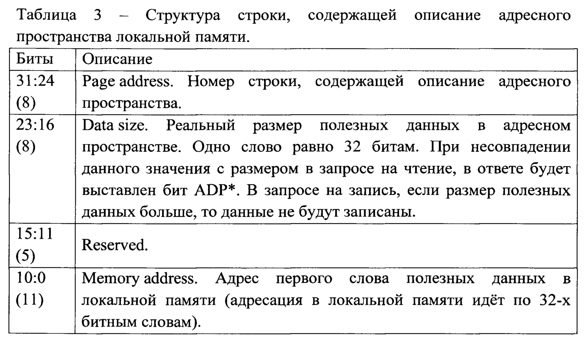
В режиме «Ведомый» в локальной памяти расположены строки для описания адресных пространств и сами адресные пространства, в которых хранятся полезные данные.In the “Slave” mode, local memory contains lines for the description of address spaces and the address spaces themselves, in which useful data is stored.
ОСД 19 производит обработку слов из таблицы дескрипторов, управляет работой DMA-контроллера 20 и работой контроллера 22.
Контроллер 22 реализует логику режимов работы «Ведущий», «Ведомый» или «Монитор». Контроллер 22 производит передачу данных между блоком 23 преобразования кода и основной памятью 24 или дополнительной памятью 25, формирует контрольные пакеты, производит обновление регистров статистики.The
Работа СФ-блока 11 в режиме «Ведущий» (фиг. 4): системное ПО формирует таблицу 33 дескрипторов в основной памяти 24 и производит настройку СФ-блока. По запуску ОСД 19 по порядку вычитывает и обрабатывает дескрипторы из таблицы 33 дескрипторов. По «Управляющей информации» из дескриптора ОСД 19 отдает соответствующие команды DMA-контроллеру 20. Параллельно с этим ОСД 19 отдает соответствующие команды контроллеру 22 на формирование транзакций для записи или чтения данных в ведомое устройство. При получении такой команды контроллер 22 выполняет последовательность действий, соответствующих типу запроса.The operation of the
В случае записи данных в ведомое устройство выполняются следующие действия: с помощью DMA-контроллера 20 происходит загрузка данных, принимаемых по системной шине AXI 26, в буфер 34 основной памяти 24. Контроллер 22 читает данные буфера 34 и передает их на шину 5. По завершению передачи данных контроллер 22 информирует об этом ОСД 19 и переходит в режим ожидания новой команды. После завершения обработки дескриптора «Управляющая информация» ОСД 19 производит обновление дескриптора «Результат выполнения транзакции» и переходит к обработке следующего дескриптора. Таким образом, можно проследить следующий поток данных: системная шина - DMA-контроллер - буфер основной памяти - контроллер шины - шина.In the case of writing data to the slave, the following actions are performed: using the
В случае чтения данных из ведомого устройства выполняются следующие действия: контроллер 22 читает данные с шины 5 и передает их в буфер 34 основной памяти 24, откуда с помощью DMA-контроллера 20 данные передаются в системную шину AXI 26. После завершения обработки дескриптора «Управляющая информация» ОСД 19 производит обновление дескриптора «Результат выполнения транзакции» и переходит к обработке следующего дескриптора. Таким образом, можно проследить следующий поток данных: шина - контроллер шины - буфер локальной памяти - DMA-контроллер - системная шина.In the case of reading data from the slave, the following actions are performed: the
Таким образом, системное ПО в начале работы однократно инициализирует СФ-блок, после этого СФ-блок без вмешательства системного ПО производит каждый цикл обмена данными по шине, перекладывая полученные данные в системную память СнК. Таким образом обеспечивается возможность автоматизировать работу СФ-блока и, тем самым, разгрузить (высвободить) ресурсы центрального процессора СнК для другой работы.Thus, the system software at the beginning of operation once initializes the SF block, after which the SF block without the intervention of the system software performs each cycle of data exchange on the bus, transferring the received data to the SoC system memory. Thus, it is possible to automate the operation of the SF block and, thereby, unload (release) the resources of the central processor of the SoC for other work.
При работе СФ-блока в качестве ведущего устройства доступ ОСД 19 к дескрипторам занимает 1 такт. Это обеспечивает детерминированное время получения задания (управляющей информации), что имеет большое значение для систем реального времени.When the SF block is operating as the master device, the
После окончания обработки таблицы дескрипторов может быть сформировано прерывание, после которого возможно обновление данных таблицы дескриптора системным ПО.After the processing of the descriptor table is completed, an interrupt may be generated, after which it is possible to update the descriptor table data with system software.
Работа СФ-блока 11 в режиме «Ведомого» (фиг. 5): СФ-блок в режиме «Ведомого» реализует логику доступа к своим адресным пространствам посредством запросов по шине. Системное ПО в начале работы однократно инициализирует СФ-блок, после чего транзакции записи или чтения данных проводятся в автоматическом режиме без участия системного ПО. Доступ к основной памяти 24 возможен только через системную шину АРВ 27. В режиме ведомого ОСД 19 не активен и обмен данными посредством DMA-контроллера 20 недоступен. По запуску контроллер 22 ожидает сигналы приема контрольного/информационного пакета от модуля 23 преобразования кода, после чего обрабатывает пакет и обращается в основную 24 (Primary memory space) или дополнительную (Secondary memory space) 25 память по адресу из контрольного пакета. В пространстве памяти лежит описание запрашиваемого адресного пространства, предназначенного для полезных данных. Одно из полей описания "Memory address" - адрес первого слова данных в адресном пространстве памяти. Если запрос был на запись, то происходит запись приходящих данных по этому адресу. Если запрос был на чтение, то происходит чтение данных из этого адреса. После окончания обработки запроса может быть вызвано прерывание, по которому происходит обновление данных системным ПО.The operation of the
Работа СФ-блока в режиме «Монитор»: СФ-блок в режиме «Монитор» выполняет функцию записи в системную память всего траффика, идущего по шине 5. Производится запись контрольных пакетов и пакетов данных. Каждый пакет, приходящий с шины 5, дополняется специальным дескриптором, идущим перед данными, и записывается в системную память. При этом записываются только информационные слова, слова CRC отбрасываются. В память записываются только те пакеты, при приеме которых не возникло ошибок. При возникновении ошибок в процессе приема принимаемый пакет отбрасывается, и будет выставлен соответствующий флаг. Работа в режиме «Монитор» похожа на работу в режиме «Ведущий» с использованием внеочередных дескрипторов.Operation of the SF block in the "Monitor" mode: The SF block in the "Monitor" mode performs the function of writing to the system memory all traffic going on the

В режиме «Монитор» ОСД 19 имеет такой же функционал, как и в режиме «Ведущий».In the "Monitor" mode, the
В СФ-блоке реализована возможность изменения длины CRC (регистр длины CRC полинома), начального значения CRC (регистр начального значения CRC) и полинома CRC (регистр значения CRC полинома) в режиме описанного в заявке протокола TSI.In the SF block, it is possible to change the CRC length (register of CRC length of the polynomial), the initial value of CRC (register of the initial value of CRC) and the polynomial CRC (register of CRC value of the polynomial) in the mode described in the TSI protocol application.
Вся информация по шине передается в коде «Манчестер-2» (фиг. 6). Этот биполярный фазоманипулированный код имеет нулевую постоянную составляющую, что очень важно в применениях с высокой скоростью передачи. Кодирование 0 и 1 производится не уровнем, а фронтом сигнала в середине тактового интервала (фиг. 6), что позволяет обеспечить побитную синхронизацию передатчика и приемника по передаваемой информации в широком диапазоне отклонения несущей частоты. Определены два вида синхросигнала (фиг. 7), которые позволяют аппаратно, следовательно, быстро определять и отличать начало пакета данных от контрольного пакета.All information on the bus is transmitted in the Manchester-2 code (Fig. 6). This bipolar phase-shifted code has a zero constant component, which is very important in applications with a high transmission rate. The coding of 0 and 1 is performed not by the level, but by the signal front in the middle of the clock interval (Fig. 6), which allows for bit-wise synchronization of the transmitter and receiver according to the transmitted information in a wide range of carrier frequency deviations. Two types of clock signal are defined (Fig. 7), which allow hardware, therefore, to quickly determine and distinguish the beginning of the data packet from the control packet.
Пакет данных (DATA) (фиг. 8) имеет формат одного или более 32 битных слов данных, завершает которые 32 битное контрольное слово. Перед ними расположен синхросигнал, полярность первой половины которого отрицательна, а вторая половина - положительная. Слова данных (полезная информация) - собственно данные, которыми обмениваются между собой модули и для передачи которых используется пакет данных. Слово контрольной суммы CRC-32 предназначено для проверки целостности всех передаваемых в пакете данных. Используется расчет CRC-32.A data packet (DATA) (Fig. 8) has the format of one or more 32 bit data words, which ends with a 32 bit control word. In front of them is a clock signal, the polarity of the first half of which is negative, and the second half is positive. Data words (useful information) - actually the data exchanged between the modules and for the transfer of which a data packet is used. The CRC-32 checksum word is intended to verify the integrity of all data transmitted in a packet. The calculation of CRC-32 is used.

Контрольный пакет (CTRL) (фиг. 9) имеет формат из 32 битного информационного слова и 32 битного слово контрольной суммы. Перед ними расположен синхросигнал, полярность первой половины которого положительна, а вторая половина - отрицательная. Контрольный пакет может выполнять функцию начала и конца сеанса связи, подтверждения приема информационного пакета или запроса информационного пакета.Checksum (CTRL) (Fig. 9) has a format of 32 bit information word and 32 bit checksum word. In front of them is a clock signal, the polarity of the first half of which is positive, and the second half is negative. The control packet may perform the function of beginning and end of a communication session, acknowledging the receipt of an information packet or requesting an information packet.

Пакет (фиг. 10), включающий контрольный пакет и пакет данных, называется информационным пакетом (CTRL+DATA).A packet (FIG. 10) including a control packet and a data packet is called an information packet (CTRL + DATA).
При запросе ведущего устройства на чтение или запись данных в ведомое устройство направляется контрольный или информационный пакет, служебная информация которых содержит поле "Primary/Secondary memory space" - поле с кодом-определителем используемой основной или дополнительной памяти (фиг. 11).When the master device requests to read or write data to the slave, a control or information packet is sent, the service information of which contains the "Primary / Secondary memory space" field - a field with the identifier code of the used main or additional memory (Fig. 11).


На запрос ведущего устройства на чтение или запись данных ведомое устройство направляет ответный контрольный или информационный пакет, служебная информация которых содержит поле "Validity of a received message" - поле признаков достоверности принятого пакета либо признаков состояния ведомого устройства (фиг. 12), что обеспечивает возможность получения различной диагностической информации.Upon the request of the master device for reading or writing data, the slave device sends a response control or information packet, the service information of which contains the field "Validity of a received message" - a field of signs of reliability of the received packet or status signs of the slave device (Fig. 12), which makes it possible obtaining various diagnostic information.
Рассмотрим возможные форматы сообщений, которыми обмениваются ведущее (Master) и ведомое (Slave) устройства путем передачи друг другу контрольных и информационных пакетов:Consider the possible message formats exchanged between the master and slave devices by transmitting control and information packets to each other:
- Формат 1 «запись данных в ведомое устройство» (фиг. 13).-
- Формат 2 «широковещательное сообщение» (фиг. 14).-
- Формат 3 «чтение данных из ведомого устройства» (фиг. 15).- Format 3 "reading data from the slave device" (Fig. 15).
- Формат 4 «невозможность ведомого устройства выдать запрашиваемые данные при чтении данных из ведомого устройства» (фиг. 16).- Format 4 "the inability of the slave to issue the requested data when reading data from the slave" (Fig. 16).
Рассмотрим форматы сообщений (фиг. 13-16) между ведущим и ведомыми электронными устройствами.Consider the message formats (Fig. 13-16) between the master and slave electronic devices.
Формат 1 предназначен для передачи данных от ведущего устройства к ведомому устройству - «запись данных в ведомое устройство» (фиг. 13). Ведущее устройство передает информационный пакет (CTRL+DATA). Ведомое устройство принимает информационный пакет, просчитывает контрольные суммы (CRC-32) 32-битного слова служебной информации и 32-битного слова (слов) данных (полезной информации) и сравнивает их значения со значениями контрольных сумм, полученных от ведущего устройства. В зависимости от результата сравнения контрольных сумм ведомое устройство либо игнорирует запрос на запись, либо принимает к исполнению. В любом случае ведомое устройство передает ведущему устройству ответный контрольный пакет (CTRL), в котором разряды [2:0] "control word" (таблица 7) имеют значения, соответствующие признакам достоверности принятого пакета.
Формат 2 предназначен для передачи данных от ведущего устройства всем ведомым устройствам - «широковещательное сообщение» (фиг. 14). Ведущее устройство передает информационный пакет (CTRL+DATA) (в поле "Terminal address" 0xFF - широковещательный адрес), а ведомые устройства принимают информационный пакет, просчитывают контрольные суммы (CRC-32) 32-битного слова служебной информации и 32-битного слова (слов) данных (полезной информации) и сравнивают их значения со значениями контрольных сумм, полученных от ведущего устройства. В зависимости от результата сравнения контрольных сумм ведомые устройства либо игнорируют запрос на запись, либо принимают к исполнению. В этом формате сообщений ведущее устройство после передачи информационного пакета не ожидает "ответного пакета" от ведомых устройств.
Формат 3 предназначен для получения данных ведомого устройства ведущим устройством - «чтение данных из ведомого устройства» (фиг. 15). Ведущее устройство передает ведомому устройству контрольный пакет (CTRL) и освобождает шину. Адресуемое ведомое устройство принимает контрольный пакет, просчитывает контрольную сумму CRC-32 32-битного слова служебной информации и сравнивает ее значение со значением контрольной суммы, полученной от ведущего устройства. В зависимости от результата сравнения контрольных сумм ведомое устройство либо игнорирует запрос на чтение, либо принимает к исполнению. При успешном сравнении ведомое устройство захватывает шину и передает ведущему устройству ответный информационный пакет (CTRL+DATA). Ведущее устройство принимает ответный информационный пакет от ведомого устройства и просчитывает контрольные суммы CRC-32 32-битного слова служебной информации и слова (слов) данных (полезной информации) и сравнивает их значения со значениями контрольных сумм, полученных от ведомого устройства. При успешном сравнении контрольных сумм информационный пакет считается принятым - чтение данных из ведомого устройства завершенным.Format 3 is intended for receiving data from the slave device by the master device - “reading data from the slave device” (Fig. 15). The master sends the control packet (CTRL) to the slave and frees the bus. The addressed slave device receives the control packet, calculates the CRC-32 checksum of the 32-bit overhead word and compares its value with the checksum value received from the master. Depending on the result of the checksum comparison, the slave device either ignores the read request or accepts it for execution. Upon successful comparison, the slave device captures the bus and transmits the response information packet (CTRL + DATA) to the master. The master device receives a response information packet from the slave device and calculates CRC-32 checksums of the 32-bit service information word and data (useful information) words (words) and compares their values with the checksums received from the slave device. Upon successful comparison of checksums, the information packet is considered accepted - the reading of data from the slave is completed.
Формат 4 «невозможно выдать запрашиваемые данные» (фиг. 16) является частным случаем формата 3, при котором происходит «чтение данных из ведомого устройства». Ведущее устройство передает ведомому устройству контрольный пакет (CTRL). Ведомое устройство принимает контрольный пакет, просчитывает его контрольную сумму и сравнивает ее значение со значением контрольной суммы, полученной от ведущего устройства. При несовпадении контрольных сумм ведомое устройство игнорирует запрос на чтение и передает ведущему устройству ответный контрольный пакет (CTRL), в котором разряды [2:0] "control word" (таблица 7) имеют значения, соответствующие признакам достоверности принятого пакета.Format 4 "it is impossible to issue the requested data" (Fig. 16) is a special case of format 3, in which "reading data from the slave device" occurs. The master sends a control packet (CTRL) to the slave. The slave device receives the checksum, calculates its checksum and compares its value with the value of the checksum received from the master. If the checksums do not match, the slave device ignores the read request and transmits the response control packet (CTRL) to the master, in which the [2: 0] "control word" bits (table 7) have values corresponding to the reliability signs of the received packet.
Пример использования изобретенийAn example of the use of inventions
Использование средств и методов заявляемого интерфейса предлагается рассмотреть на примере работы контроллера с программируемой логикой 35 (далее ПЛК) (анг. PLC), который используется в качестве устройства противоаварийной автоматической защиты (фиг. 17).The use of the tools and methods of the proposed interface is proposed to be considered on the example of the operation of the controller with programmable logic 35 (hereinafter PLC) (eng. PLC), which is used as an emergency automatic protection device (Fig. 17).
Следует понимать, что описанный здесь пример осуществления используется только для объяснения настоящего изобретения и не используется для ограничения объема и отрасли применения изобретения, которое может быть использовано и в робототехнике, медицине, автомобильном или железнодорожном транспорте.It should be understood that the embodiment described here is used only to explain the present invention and is not used to limit the scope and scope of the invention, which can be used in robotics, medicine, automobile or rail transport.
Описанные в заявке средства интерфейса, в том числе протокол TSI, могут быть использованы в ПЛК для обмена данными по внутренней шине и для обеспечения возможности отключения управляющего сигнала на выходе ПЛК при диагностировании отказа программируемого вычислительного устройства (микроконтроллера, микропроцессора, ядер СнК) в модуле вывода сигналов для того, чтобы предотвратить аварийную (опасную) ситуацию на объекте управления.The interface tools described in the application, including the TSI protocol, can be used in the PLC to exchange data on the internal bus and to enable the control signal to be switched off at the PLC output when diagnosing a failure of a programmable computing device (microcontroller, microprocessor, SoC cores) in the output module signals in order to prevent an emergency (dangerous) situation at the control object.
ПЛК 35 содержит модуль центрального процессора 36 (далее модуль ЦП) (анг. module CPU) и модули ввода-вывода 37 (анг. I/O modules), предназначенные для работы с различными типами сигналов: ввода сигналов термопар и термопреобразователей сопротивления; ввода и вывода унифицированных аналоговых сигналов среднего уровня; ввода и вывода дискретных сигналов. На фиг. 17 также показано оборудование объекта управления 38: контрольно-измерительный прибор - датчик 39 и исполнительные механизмы - двигатель 40 и клапан 41.
При описании работы ПЛК следует оговорить следующие понятия и условия, используемые в данной заявке:When describing the operation of the PLC, the following concepts and conditions used in this application should be stipulated:
- В данной заявке описана работа ПЛК, не имеющего резервированных и дублированных элементов. Поэтому, при неисправной работе элементов, должны быть приняты меры по отключению управляющего сигнала на выходе ПЛК. Это приведет к тому, что контакты контактора 42, через который на исполнительные механизмы подается питание, будут разомкнуты. Это, в свою очередь, приведет к тому, что регулирующий или отсечной клапан 41 займут безопасное для технологического процесса положение, а двигатель 40 будет остановлен.- This application describes the operation of a PLC that does not have redundant and duplicated elements. Therefore, in case of malfunctioning of the elements, measures must be taken to disable the control signal at the output of the PLC. This will lead to the fact that the contacts of the
- Процесс противоаварийной защиты объекта управления требует непрерывного измерения технологических параметров. Одна итерация, включающая замер технологического параметра, его обсчет и выработку воздействия на исполнительные механизмы, называется рабочим циклом ПЛК. Работа ПЛК состоит из постоянного повторения последовательности действий, входящих в рабочий цикл.- The process of emergency protection of the control object requires continuous measurement of technological parameters. One iteration, including the measurement of a technological parameter, its calculation and the generation of effects on actuators, is called the PLC duty cycle. The operation of the PLC consists of constantly repeating the sequence of actions included in the duty cycle.
- Промышленные ПЛК являются системами реального времени. Корректность функционирования систем реального времени определяется не только корректностью выполнения вычислений, но и временем, за которое получен требуемый результат - время реакции. Если вычисления выполнены некорректно или не выполнены требования по времени, то считается, что произошел отказ.- Industrial PLCs are real-time systems. The correct functioning of real-time systems is determined not only by the correctness of the calculations, but also by the time for which the desired result is obtained - the reaction time. If the calculations are performed incorrectly or the time requirements are not met, then it is considered that a failure has occurred.
Модуль ЦП 36 содержит следующие функциональные блоки: интерфейсный блок 43, работающий в режиме «Ведущий» (анг. Interface block MASTER), ОЗУ 44 (анг. RAM), программируемое вычислительное устройство 45 (анг. CPU) (далее ЦП) и флэш-память 46 (анг. Flash).The
Модуль ввода 47 содержит следующие функциональные блоки: интерфейсный блок 48, работающий в режиме «Ведомый» (анг. Interface block SLAVE), программируемое вычислительное устройство 49 (анг. CPU) (далее ЦП), ОЗУ 50 (анг. RAM), блок ввода-вывода 51 (анг. I/O block) и флэш-память 52 (анг. Flash). На фиг. 17 схематично изображены только необходимые для раскрытия изобретений элементы ПЛК и интерфейсного блока 48, а именно контроллер 53 и основная память 54. Блок ввода-вывода 51 предназначен для ввода сигналов по измерительной шине 55 с датчиков 39, контролирующих важные для безопасного состояния объекта управления параметры.
Модуль вывода 56 содержит следующие функциональные блоки: интерфейсный блок 57, работающий в режиме «Ведомый» (анг. Interface block SLAVE), программируемое вычислительное устройство 58 (анг. CPU) (далее ЦП), ОЗУ 59 (анг. RAM), блок ввода-вывода 60 (анг. I/O block) и флэш-память 61 (анг. Flash). На фиг. 17 схематично изображены только необходимые для раскрытия изобретений устройства интерфейсного блока 57, а именно контроллер 62, основную память 63 и дополнительную память 64. Модуль вывода 56 может содержать логический элемент И 65 и ключ 66 в цепи 67 питания.
Управление контактором 42 осуществляется через реле 68. Подача напряжения (24 V) на реле 68 происходит при закрытом ключе 66 в цепи 67 питания. Управление ключом 66 происходит по шине управления 69.The
Следует отметить, что интерфейсные блоки 43, 48, 57, ЦП 44, 49, 58, ОЗУ 44, 50, 59 и блоки ввода-вывода 51, 60 могут быть как функциональными блоками СнК 12, так и отдельными устройствами на плате.It should be noted that the interface blocks 43, 48, 57,
Работа системы связи при инициализацииCommunication system operation during initialization
В процессе инициализации осуществляется настройка совокупности значений параметров, определяющих работу интерфейсных блоков (СФ-блоков СнК). Для каждого из трех режимов работы интерфейсного блока инициализация различна.During the initialization process, a set of parameter values is determined that determines the operation of interface units (SF blocks of SoC). For each of the three operating modes of the interface unit, the initialization is different.
Информация, необходимая для инициализации, определяется пользователем в процессе проектирования и загружается в процессе конфигурации во флэш-память. При включении питания содержимое (код программы и данные инициализации) флэш-памяти автоматически загружается в оперативную память ОЗУ, связанную с ЦП. При инициализации системное ПО однократно определяет работу интерфейсного блока в режим «Ведущего», или в режим «Ведомого», или в режим «Монитор», для чего загружаются контрольные регистры блока, в которые выставляются необходимые прерывания, тайминги и время цикла шины с учетом тактовой частоты работы блока. При этом в интерфейсный блок, который будет работать в режиме «Ведущий», в основную память записывается таблица дескрипторов. После этого операции чтения или записи данных по шине могут проводиться в автоматическом режиме без участия системного ПО.The information necessary for initialization is determined by the user during the design process and is loaded into the flash memory during the configuration process. When the power is turned on, the contents (program code and initialization data) of the flash memory are automatically loaded into the RAM memory associated with the CPU. During initialization, the system software once determines the operation of the interface unit in the “Lead” mode, or in the “Slave” mode, or in the “Monitor” mode, for which the control registers of the block are loaded, in which the necessary interrupts, timings and bus cycle time are set taking into account the clock unit operation frequencies. At the same time, a descriptor table is written to the interface unit, which will operate in the “Lead” mode, in the main memory. After this, the operation of reading or writing data on the bus can be carried out automatically without the participation of system software.
Режим штатной работы устройства защитыThe standard mode of operation of the protection device
Перед началом работы ПЛК выполняется конфигурирование всех модулей ПЛК (настройка сетевых интерфейсов, системы ввода/вывода, службы диагностики, установка системного времени и режима его синхронизации, а также некоторых других параметров и системных сервисов). После перезагрузки ПЛК его модули начинают работу в нормальном (штатном) режиме.Before starting the PLC, all PLC modules are configured (setting up network interfaces, input / output systems, diagnostic services, setting the system time and its synchronization mode, as well as some other parameters and system services). After a PLC reboot, its modules start working in normal (normal) mode.
Перед тем, как описать работу ПЛК в нормальном (штатном) режиме следует описать работу логического элемента И 65. При подаче на вход логического элемента И 65 по основной шине 70 сигнала В1=1 (высокого уровня) и по дополнительной шине 71 сигнала В2=1 (высокого уровня), на выходе логического элемента И 65 по управляющей шине 69 будет выдан сигнал В3=1 (высокого уровня). Перед тем, как ПЛК начнет выполнение цикличной работы, из модуля ЦП 36 в модуль вывода 56 направляется на запись информационный пакет, в служебных данных которого указана дополнительная память (Secondary memory space) 64 интерфейсного блока 57 модуля вывода 56. Это делается для того, чтобы из дополнительной памяти 64 по дополнительной шине 71, соединяющей напрямую дополнительную память 64 и логический элемент И 65, направить в логический элемент И 65 сигнал В2=1 (высокого уровня). Наличие такого сигнала на входе логического элемента И 65 позволит при подаче по основной шине 70 сигнала B1=1 (высокого уровня) получить на управляющей шине 69 сигнал В3=1 (высокого уровня), который закроет ключ 66.Before describing the operation of the PLC in the normal (normal) mode, it is necessary to describe the operation of the And 65 logic element. When the And 65 logic element is input via the
При штатной работе от датчика 39 по измерительной шине 55 поступает сигнал в блок ввода-вывода 51, где он преобразуется в цифровой формат и в цифровом виде передается на вход ЦП 49, откуда данные передаются в основную память 54 интерфейсного блока 48. Для получения данных из модуля ввода 47 интерфейсный блок 43 модуля ЦП 36 передает в шину 5 контрольный пакет с адресом модуля ввода 47, с основной памятью 54 и запросом на чтение данных. Интерфейсный блок 48 принимает контрольный пакет, проверяет его на достоверность полученной информации, после чего передает в модуль ЦП 36 ответный информационный пакет. Полученный ответный информационный пакет в интерфейсном блоке 43 модуля ЦП 36 проверяется на достоверность полученной информации, после чего полезные данные записываются в буфер локальной памяти интерфейсного блока 43. ЦП 45 модуля ЦП 36 непрерывно принимает исполняемый код прикладной программы, представляющей собой арифметические или логические операции, из ОЗУ 44 и извлекает текущие данные, переданные в ОЗУ 44 из буфера локальной памяти интерфейсного блока 43. Результат операций над данными вновь передается из ЦП 45 в ОЗУ 44, откуда передается в буфер локальной памяти интерфейсного блока 43. Затем формируется информационный пакет, служебные данные которого содержат адрес модуля вывода 56 и указание на то, что данные должны быть записаны в основную память (Primary memory space) 63. Интерфейсный блок 43 модуля ЦП 36 передает информационный пакет в шину 5. Интерфейсный блок 57 модуля вывода 56 принимает информационный пакет и проверяет его на достоверность полученной информации, после чего данные записываются в основную память 63, а в модуль ЦП 36 отправляется ответный контрольный пакет. Данные из основной памяти 63 передаются ЦП 58 в блок ввода-вывода 60, откуда сигнал по основной шине 70 поступает в логический элемент И 65. В случае, когда значение измеряемого датчиком 39 параметра соответствует нормальным значениям технологического процесса, в модуль вывода 56 будет направлен информационный пакет с данными, преобразование которых даст по основной шине 70 сигнал В1=1 (высокого уровня), что приведет к закрыванию ключа.During normal operation, the
В случае, когда значение измеряемого параметра превысило предельно допустимое значение, в модуль вывода 56 будет направлен информационный пакет с данными, преобразование которых даст по основной шине 70 сигнал В1=0 (низкого уровня), что приведет к открыванию ключа.In the case when the value of the measured parameter exceeded the maximum permissible value, an information packet with data will be sent to the
Режим нештатной работы устройства защитыAbnormal operation mode of the protection device
Нештатная работа устройства защиты может быть вызвана большим количеством факторов. Далее будет описан режим нештатной работы, вызванной отказом ЦП 58 модуля вывода 56. Если рассматривать выше описанную штатную работу модуля вывода 56, в котором ЦП 58 передавало данные из основной памяти 63 в блок ввода-вывода 60, то «зависшее» или неисправное ЦП 58 не передаст очередные данные, которые бы позволили изменить уровень сигнала в основной шине 70. О рабочем состоянии ЦП 58 сигнализирует счетчик активности ЦП (анг. Life bit counter), значение которого увеличивается на единицу, в случае успешной передачи данных, осуществляемой ЦП 58. Данные счетчика передаются в ответном контрольном пакете, что позволяет модулю ЦП 36 судить о работоспособном состоянии ЦП 58 модуля вывода 56. В случае, если значения счетчика не изменились, что свидетельствует об отказе ЦП 58, модуль ЦП 36 фиксирует отказ ЦП 58 в модуле вывода 56 и формирует информационный пакет, в котором содержится указание на запись данных в дополнительную память 64 модуля вывода 56. Запись данных в дополнительную память 64 позволит изменить уровень сигнала в дополнительной шине 71. Так, если принять, что перед началом цикла работы ПЛК в дополнительной шине был сигнал В2=1 (высокого уровня), то его следует изменить на сигнал В2=0 (низкого уровня). Это приведет к изменению сигнала В3=0 на управляющей шине 69 и открытию ключа 66 в независимости от состояния сигнала B1 Abnormal operation of the protection device can be caused by a large number of factors. Next, an abnormal operation mode caused by a failure of the
Дополнительная шина 71 может быть выведена на физический вывод микросхемы, и, например, подавать сигнал на ключ в цепи питания лампочки сигнализации, что позволит сигнализировать об отказе вычислительного устройства модуля вывода.An
Также дополнительную память в интерфейсном блоке можно использовать при отказе ЦП 49 в модуле ввода 47 для снятия сигнала с дискретного датчика.Also, additional memory in the interface unit can be used in the event of a
Claims (7)
Priority Applications (1)
| Application Number | Priority Date | Filing Date | Title |
|---|---|---|---|
| RU2018146099A RU2705421C1 (en) | 2018-12-25 | 2018-12-25 | Method of transmitting data over a bus, a communication system for realizing said method and an automatic protection device for preventing an emergency situation at a control object |
Applications Claiming Priority (1)
| Application Number | Priority Date | Filing Date | Title |
|---|---|---|---|
| RU2018146099A RU2705421C1 (en) | 2018-12-25 | 2018-12-25 | Method of transmitting data over a bus, a communication system for realizing said method and an automatic protection device for preventing an emergency situation at a control object |
Publications (1)
| Publication Number | Publication Date |
|---|---|
| RU2705421C1 true RU2705421C1 (en) | 2019-11-07 |
Family
ID=68501126
Family Applications (1)
| Application Number | Title | Priority Date | Filing Date |
|---|---|---|---|
| RU2018146099A RU2705421C1 (en) | 2018-12-25 | 2018-12-25 | Method of transmitting data over a bus, a communication system for realizing said method and an automatic protection device for preventing an emergency situation at a control object |
Country Status (1)
| Country | Link |
|---|---|
| RU (1) | RU2705421C1 (en) |
Cited By (2)
| Publication number | Priority date | Publication date | Assignee | Title |
|---|---|---|---|---|
| RU2791433C1 (en) * | 2019-03-27 | 2023-03-07 | Уси Хиски Медикал Текнолоджис Ко., Лтд. | Device and method for data transmission and readable data carrier |
| US11803490B2 (en) | 2019-03-27 | 2023-10-31 | Wuxi Hisky Medical Technologies Co., Ltd. | Apparatus and method for data transmission and readable storage medium |
Citations (4)
| Publication number | Priority date | Publication date | Assignee | Title |
|---|---|---|---|---|
| WO2002075939A2 (en) * | 2001-03-16 | 2002-09-26 | Aura Communications, Inc. | Wireless communication over a transducer device |
| EA200500670A1 (en) * | 2002-10-17 | 2005-08-25 | Эмбиент Корпорейшн | DATA TURN SENDER FOR DATA TRANSMISSION ON POWER BUS |
| RU2013149027A (en) * | 2011-04-06 | 2015-05-20 | Роберт Бош Гмбх | METHOD AND DEVICE FOR ADAPTING RELIABILITY OF DATA TRANSMISSION IN A SERIAL BUS SYSTEM |
| EA201700029A1 (en) * | 2016-12-28 | 2018-02-28 | Закрытое акционерное общество "ТеконГруп" | METHOD OF ADAPTIVE DATA TRANSFER IN INDUSTRIAL CONTROLLER |
-
2018
- 2018-12-25 RU RU2018146099A patent/RU2705421C1/en active
Patent Citations (4)
| Publication number | Priority date | Publication date | Assignee | Title |
|---|---|---|---|---|
| WO2002075939A2 (en) * | 2001-03-16 | 2002-09-26 | Aura Communications, Inc. | Wireless communication over a transducer device |
| EA200500670A1 (en) * | 2002-10-17 | 2005-08-25 | Эмбиент Корпорейшн | DATA TURN SENDER FOR DATA TRANSMISSION ON POWER BUS |
| RU2013149027A (en) * | 2011-04-06 | 2015-05-20 | Роберт Бош Гмбх | METHOD AND DEVICE FOR ADAPTING RELIABILITY OF DATA TRANSMISSION IN A SERIAL BUS SYSTEM |
| EA201700029A1 (en) * | 2016-12-28 | 2018-02-28 | Закрытое акционерное общество "ТеконГруп" | METHOD OF ADAPTIVE DATA TRANSFER IN INDUSTRIAL CONTROLLER |
Cited By (2)
| Publication number | Priority date | Publication date | Assignee | Title |
|---|---|---|---|---|
| RU2791433C1 (en) * | 2019-03-27 | 2023-03-07 | Уси Хиски Медикал Текнолоджис Ко., Лтд. | Device and method for data transmission and readable data carrier |
| US11803490B2 (en) | 2019-03-27 | 2023-10-31 | Wuxi Hisky Medical Technologies Co., Ltd. | Apparatus and method for data transmission and readable storage medium |
Similar Documents
| Publication | Publication Date | Title |
|---|---|---|
| US5313386A (en) | Programmable controller with backup capability | |
| US7120820B2 (en) | Redundant control system and control computer and peripheral unit for a control system of this type | |
| CN201740999U (en) | Input and/or output security module for automation equipment | |
| EP0196911B1 (en) | Local area networks | |
| US6466539B1 (en) | Bus system | |
| US6853292B1 (en) | Security control system, method for the operation thereof | |
| US7269465B2 (en) | Control system for controlling safety-critical processes | |
| CN100480913C (en) | Safety-oriented control system | |
| CA2019373C (en) | Interrupt structure for network interface circuit | |
| US5644700A (en) | Method for operating redundant master I/O controllers | |
| RU2665890C2 (en) | Data management and transmission system, gateway module, input/output module and process control method | |
| US5392424A (en) | Apparatus for detecting parity errors among asynchronous digital signals | |
| CA2592908A1 (en) | Line diagnostic device, bus system, line diagnostic method, bus system control method, and line diagnostic program | |
| CN104808572A (en) | High-integrity PLC controller based on function safety | |
| US7774638B1 (en) | Uncorrectable data error containment systems and methods | |
| JPH04364562A (en) | Method of ensuring data stored in primary database and secondary database in process control system | |
| CN103744753A (en) | Data interaction method and device for dual systems | |
| RU2705421C1 (en) | Method of transmitting data over a bus, a communication system for realizing said method and an automatic protection device for preventing an emergency situation at a control object | |
| US4783733A (en) | Fault tolerant communications controller system | |
| CN114615106B (en) | Ring data processing system, method and network equipment | |
| CN210380890U (en) | Communication system and SIS system of Modbus equipment | |
| CN112052113B (en) | Communication link layer message single event effect fault tolerance method and device | |
| CN110687854B (en) | PA bus controller and PA bus control system | |
| CN112822290A (en) | Train network communication device, system and method | |
| RU2691886C1 (en) | Complex-functional unit for vlsi-type system on chip |