RU2688582C2 - Water treatment system for local use (embodiments) - Google Patents
Water treatment system for local use (embodiments) Download PDFInfo
- Publication number
- RU2688582C2 RU2688582C2 RU2015108369A RU2015108369A RU2688582C2 RU 2688582 C2 RU2688582 C2 RU 2688582C2 RU 2015108369 A RU2015108369 A RU 2015108369A RU 2015108369 A RU2015108369 A RU 2015108369A RU 2688582 C2 RU2688582 C2 RU 2688582C2
- Authority
- RU
- Russia
- Prior art keywords
- water
- treatment system
- water treatment
- chamber
- flow path
- Prior art date
Links
- XLYOFNOQVPJJNP-UHFFFAOYSA-N water Substances O XLYOFNOQVPJJNP-UHFFFAOYSA-N 0.000 title claims abstract description 362
- 238000004891 communication Methods 0.000 claims abstract description 41
- 239000012530 fluid Substances 0.000 claims abstract description 32
- 238000012545 processing Methods 0.000 claims abstract description 27
- 239000008213 purified water Substances 0.000 claims abstract description 19
- 239000000463 material Substances 0.000 claims description 89
- 238000001914 filtration Methods 0.000 claims description 77
- 239000000356 contaminant Substances 0.000 claims description 13
- 238000000034 method Methods 0.000 claims description 6
- 239000013013 elastic material Substances 0.000 claims description 5
- 239000004615 ingredient Substances 0.000 claims description 5
- 238000004659 sterilization and disinfection Methods 0.000 claims description 4
- 230000008569 process Effects 0.000 claims description 2
- 230000000977 initiatory effect Effects 0.000 claims 2
- 238000000746 purification Methods 0.000 abstract description 7
- 239000000126 substance Substances 0.000 abstract description 2
- 238000005192 partition Methods 0.000 description 45
- 230000000249 desinfective effect Effects 0.000 description 44
- 238000007789 sealing Methods 0.000 description 25
- 230000005855 radiation Effects 0.000 description 18
- OKTJSMMVPCPJKN-UHFFFAOYSA-N Carbon Chemical compound [C] OKTJSMMVPCPJKN-UHFFFAOYSA-N 0.000 description 15
- 239000003245 coal Substances 0.000 description 15
- 239000000645 desinfectant Substances 0.000 description 15
- 239000002245 particle Substances 0.000 description 15
- 238000012986 modification Methods 0.000 description 14
- 230000004048 modification Effects 0.000 description 14
- 238000004140 cleaning Methods 0.000 description 13
- 238000011045 prefiltration Methods 0.000 description 13
- 229910052799 carbon Inorganic materials 0.000 description 11
- 238000004804 winding Methods 0.000 description 11
- 239000003344 environmental pollutant Substances 0.000 description 9
- 231100000719 pollutant Toxicity 0.000 description 9
- 238000009281 ultraviolet germicidal irradiation Methods 0.000 description 9
- 238000002955 isolation Methods 0.000 description 7
- 239000010453 quartz Substances 0.000 description 7
- VYPSYNLAJGMNEJ-UHFFFAOYSA-N silicon dioxide Inorganic materials O=[Si]=O VYPSYNLAJGMNEJ-UHFFFAOYSA-N 0.000 description 7
- 238000013461 design Methods 0.000 description 6
- 229920001971 elastomer Polymers 0.000 description 6
- 238000009434 installation Methods 0.000 description 6
- 238000009413 insulation Methods 0.000 description 5
- 230000006835 compression Effects 0.000 description 4
- 238000007906 compression Methods 0.000 description 4
- 244000005700 microbiome Species 0.000 description 4
- 239000011230 binding agent Substances 0.000 description 3
- 239000000806 elastomer Substances 0.000 description 3
- 239000004744 fabric Substances 0.000 description 3
- 239000012510 hollow fiber Substances 0.000 description 3
- 230000001939 inductive effect Effects 0.000 description 3
- 239000007788 liquid Substances 0.000 description 3
- 239000000203 mixture Substances 0.000 description 3
- 230000002093 peripheral effect Effects 0.000 description 3
- 239000004033 plastic Substances 0.000 description 3
- 239000011347 resin Substances 0.000 description 3
- 229920005989 resin Polymers 0.000 description 3
- 235000013361 beverage Nutrition 0.000 description 2
- 239000013536 elastomeric material Substances 0.000 description 2
- -1 for example Chemical compound 0.000 description 2
- 239000011796 hollow space material Substances 0.000 description 2
- 239000004973 liquid crystal related substance Substances 0.000 description 2
- 238000012423 maintenance Methods 0.000 description 2
- 230000007246 mechanism Effects 0.000 description 2
- 239000012528 membrane Substances 0.000 description 2
- 239000002121 nanofiber Substances 0.000 description 2
- NJPPVKZQTLUDBO-UHFFFAOYSA-N novaluron Chemical compound C1=C(Cl)C(OC(F)(F)C(OC(F)(F)F)F)=CC=C1NC(=O)NC(=O)C1=C(F)C=CC=C1F NJPPVKZQTLUDBO-UHFFFAOYSA-N 0.000 description 2
- 238000011144 upstream manufacturing Methods 0.000 description 2
- ZAMOUSCENKQFHK-UHFFFAOYSA-N Chlorine atom Chemical compound [Cl] ZAMOUSCENKQFHK-UHFFFAOYSA-N 0.000 description 1
- KRHYYFGTRYWZRS-UHFFFAOYSA-M Fluoride anion Chemical compound [F-] KRHYYFGTRYWZRS-UHFFFAOYSA-M 0.000 description 1
- 101000973623 Homo sapiens Neuronal growth regulator 1 Proteins 0.000 description 1
- 102100022223 Neuronal growth regulator 1 Human genes 0.000 description 1
- 239000004793 Polystyrene Substances 0.000 description 1
- 238000007792 addition Methods 0.000 description 1
- 230000000844 anti-bacterial effect Effects 0.000 description 1
- 238000013459 approach Methods 0.000 description 1
- 229910052785 arsenic Inorganic materials 0.000 description 1
- RQNWIZPPADIBDY-UHFFFAOYSA-N arsenic atom Chemical compound [As] RQNWIZPPADIBDY-UHFFFAOYSA-N 0.000 description 1
- 239000011324 bead Substances 0.000 description 1
- 229910052801 chlorine Inorganic materials 0.000 description 1
- 239000000460 chlorine Substances 0.000 description 1
- 230000008878 coupling Effects 0.000 description 1
- 238000010168 coupling process Methods 0.000 description 1
- 238000005859 coupling reaction Methods 0.000 description 1
- 238000007599 discharging Methods 0.000 description 1
- 239000003651 drinking water Substances 0.000 description 1
- 235000020188 drinking water Nutrition 0.000 description 1
- 238000005516 engineering process Methods 0.000 description 1
- 230000002349 favourable effect Effects 0.000 description 1
- 150000002222 fluorine compounds Chemical class 0.000 description 1
- 230000006698 induction Effects 0.000 description 1
- 238000003780 insertion Methods 0.000 description 1
- 230000037431 insertion Effects 0.000 description 1
- 230000003993 interaction Effects 0.000 description 1
- 238000005342 ion exchange Methods 0.000 description 1
- 210000001503 joint Anatomy 0.000 description 1
- 238000002372 labelling Methods 0.000 description 1
- 238000000465 moulding Methods 0.000 description 1
- 150000002823 nitrates Chemical class 0.000 description 1
- 244000052769 pathogen Species 0.000 description 1
- 229920002223 polystyrene Polymers 0.000 description 1
- 238000007639 printing Methods 0.000 description 1
- 238000005086 pumping Methods 0.000 description 1
- 230000004044 response Effects 0.000 description 1
- 230000008054 signal transmission Effects 0.000 description 1
- 229920002379 silicone rubber Polymers 0.000 description 1
- 239000004945 silicone rubber Substances 0.000 description 1
- 235000014214 soft drink Nutrition 0.000 description 1
- 239000000725 suspension Substances 0.000 description 1
- 230000026676 system process Effects 0.000 description 1
- 229920001169 thermoplastic Polymers 0.000 description 1
- 239000004416 thermosoftening plastic Substances 0.000 description 1
- 230000000699 topical effect Effects 0.000 description 1
- 238000012546 transfer Methods 0.000 description 1
- 238000000108 ultra-filtration Methods 0.000 description 1
Images


Classifications
-
- B—PERFORMING OPERATIONS; TRANSPORTING
- B01—PHYSICAL OR CHEMICAL PROCESSES OR APPARATUS IN GENERAL
- B01D—SEPARATION
- B01D36/00—Filter circuits or combinations of filters with other separating devices
-
- B—PERFORMING OPERATIONS; TRANSPORTING
- B01—PHYSICAL OR CHEMICAL PROCESSES OR APPARATUS IN GENERAL
- B01D—SEPARATION
- B01D35/00—Filtering devices having features not specifically covered by groups B01D24/00 - B01D33/00, or for applications not specifically covered by groups B01D24/00 - B01D33/00; Auxiliary devices for filtration; Filter housing constructions
- B01D35/02—Filters adapted for location in special places, e.g. pipe-lines, pumps, stop-cocks
- B01D35/04—Plug, tap, or cock filters filtering elements mounted in or on a faucet
-
- B—PERFORMING OPERATIONS; TRANSPORTING
- B01—PHYSICAL OR CHEMICAL PROCESSES OR APPARATUS IN GENERAL
- B01D—SEPARATION
- B01D35/00—Filtering devices having features not specifically covered by groups B01D24/00 - B01D33/00, or for applications not specifically covered by groups B01D24/00 - B01D33/00; Auxiliary devices for filtration; Filter housing constructions
- B01D35/14—Safety devices specially adapted for filtration; Devices for indicating clogging
- B01D35/147—Bypass or safety valves
-
- C—CHEMISTRY; METALLURGY
- C02—TREATMENT OF WATER, WASTE WATER, SEWAGE, OR SLUDGE
- C02F—TREATMENT OF WATER, WASTE WATER, SEWAGE, OR SLUDGE
- C02F1/00—Treatment of water, waste water, or sewage
-
- C—CHEMISTRY; METALLURGY
- C02—TREATMENT OF WATER, WASTE WATER, SEWAGE, OR SLUDGE
- C02F—TREATMENT OF WATER, WASTE WATER, SEWAGE, OR SLUDGE
- C02F1/00—Treatment of water, waste water, or sewage
- C02F1/008—Control or steering systems not provided for elsewhere in subclass C02F
-
- C—CHEMISTRY; METALLURGY
- C02—TREATMENT OF WATER, WASTE WATER, SEWAGE, OR SLUDGE
- C02F—TREATMENT OF WATER, WASTE WATER, SEWAGE, OR SLUDGE
- C02F1/00—Treatment of water, waste water, or sewage
- C02F1/28—Treatment of water, waste water, or sewage by sorption
-
- C—CHEMISTRY; METALLURGY
- C02—TREATMENT OF WATER, WASTE WATER, SEWAGE, OR SLUDGE
- C02F—TREATMENT OF WATER, WASTE WATER, SEWAGE, OR SLUDGE
- C02F1/00—Treatment of water, waste water, or sewage
- C02F1/30—Treatment of water, waste water, or sewage by irradiation
- C02F1/32—Treatment of water, waste water, or sewage by irradiation with ultraviolet light
- C02F1/325—Irradiation devices or lamp constructions
-
- C—CHEMISTRY; METALLURGY
- C02—TREATMENT OF WATER, WASTE WATER, SEWAGE, OR SLUDGE
- C02F—TREATMENT OF WATER, WASTE WATER, SEWAGE, OR SLUDGE
- C02F9/00—Multistage treatment of water, waste water or sewage
- C02F9/20—Portable or detachable small-scale multistage treatment devices, e.g. point of use or laboratory water purification systems
-
- C—CHEMISTRY; METALLURGY
- C02—TREATMENT OF WATER, WASTE WATER, SEWAGE, OR SLUDGE
- C02F—TREATMENT OF WATER, WASTE WATER, SEWAGE, OR SLUDGE
- C02F1/00—Treatment of water, waste water, or sewage
- C02F1/001—Processes for the treatment of water whereby the filtration technique is of importance
-
- C—CHEMISTRY; METALLURGY
- C02—TREATMENT OF WATER, WASTE WATER, SEWAGE, OR SLUDGE
- C02F—TREATMENT OF WATER, WASTE WATER, SEWAGE, OR SLUDGE
- C02F1/00—Treatment of water, waste water, or sewage
- C02F1/006—Water distributors either inside a treatment tank or directing the water to several treatment tanks; Water treatment plants incorporating these distributors, with or without chemical or biological tanks
-
- C—CHEMISTRY; METALLURGY
- C02—TREATMENT OF WATER, WASTE WATER, SEWAGE, OR SLUDGE
- C02F—TREATMENT OF WATER, WASTE WATER, SEWAGE, OR SLUDGE
- C02F1/00—Treatment of water, waste water, or sewage
- C02F1/28—Treatment of water, waste water, or sewage by sorption
- C02F1/283—Treatment of water, waste water, or sewage by sorption using coal, charred products, or inorganic mixtures containing them
-
- C—CHEMISTRY; METALLURGY
- C02—TREATMENT OF WATER, WASTE WATER, SEWAGE, OR SLUDGE
- C02F—TREATMENT OF WATER, WASTE WATER, SEWAGE, OR SLUDGE
- C02F2201/00—Apparatus for treatment of water, waste water or sewage
- C02F2201/002—Construction details of the apparatus
- C02F2201/003—Coaxial constructions, e.g. a cartridge located coaxially within another
-
- C—CHEMISTRY; METALLURGY
- C02—TREATMENT OF WATER, WASTE WATER, SEWAGE, OR SLUDGE
- C02F—TREATMENT OF WATER, WASTE WATER, SEWAGE, OR SLUDGE
- C02F2201/00—Apparatus for treatment of water, waste water or sewage
- C02F2201/002—Construction details of the apparatus
- C02F2201/006—Cartridges
-
- C—CHEMISTRY; METALLURGY
- C02—TREATMENT OF WATER, WASTE WATER, SEWAGE, OR SLUDGE
- C02F—TREATMENT OF WATER, WASTE WATER, SEWAGE, OR SLUDGE
- C02F2201/00—Apparatus for treatment of water, waste water or sewage
- C02F2201/32—Details relating to UV-irradiation devices
-
- C—CHEMISTRY; METALLURGY
- C02—TREATMENT OF WATER, WASTE WATER, SEWAGE, OR SLUDGE
- C02F—TREATMENT OF WATER, WASTE WATER, SEWAGE, OR SLUDGE
- C02F2201/00—Apparatus for treatment of water, waste water or sewage
- C02F2201/32—Details relating to UV-irradiation devices
- C02F2201/322—Lamp arrangement
- C02F2201/3223—Single elongated lamp located on the central axis of a turbular reactor
-
- C—CHEMISTRY; METALLURGY
- C02—TREATMENT OF WATER, WASTE WATER, SEWAGE, OR SLUDGE
- C02F—TREATMENT OF WATER, WASTE WATER, SEWAGE, OR SLUDGE
- C02F2209/00—Controlling or monitoring parameters in water treatment
-
- C—CHEMISTRY; METALLURGY
- C02—TREATMENT OF WATER, WASTE WATER, SEWAGE, OR SLUDGE
- C02F—TREATMENT OF WATER, WASTE WATER, SEWAGE, OR SLUDGE
- C02F2301/00—General aspects of water treatment
- C02F2301/08—Multistage treatments, e.g. repetition of the same process step under different conditions
-
- C—CHEMISTRY; METALLURGY
- C02—TREATMENT OF WATER, WASTE WATER, SEWAGE, OR SLUDGE
- C02F—TREATMENT OF WATER, WASTE WATER, SEWAGE, OR SLUDGE
- C02F2303/00—Specific treatment goals
- C02F2303/04—Disinfection
Abstract
Description
Данное изобретение относится к системам обработки воды (СОВ) и, в частности, к устройствам СОВ обработки воды домашнего или коммерческого применения.This invention relates to water treatment systems (SOW) and, in particular, to SOW devices for domestic or commercial water treatment.
Обычно системы обработки воды применяют для обработки воды в распределительной системе. Система обработки воды удаляет болезнетворные микроорганизмы, химические загрязняющие вещества и мутность из воды, которую человек использует для личного потребления. Устройства обработки воды могут использовать компоненты фильтрации, ионного обмена, ультрафиолетового облучения и подобное, для очистки воды, при ее пропускании через устройство от источника воды до точки выдачи, например, водопроводного крана строения.Typically, water treatment systems are used to process water in a distribution system. The water treatment system removes pathogens, chemical pollutants and turbidity from water that a person uses for personal consumption. Water treatment devices may use components of filtration, ion exchange, ultraviolet irradiation and the like to purify water by passing it through the device from a water source to the point of issue, for example, of a building tap.
Традиционные системы обработки воды соединяют муниципальное или индивидуальное водоснабжение под давлением с устройством распределения воды. Например, встроенная система обработки воды, вида, применяемого в местах проживания или коммерческих предприятиях, обеспечивает жидкостное сообщение между линией водоснабжения под давлением и водопроводным краном. Поскольку вода течет через систему, то система обрабатывает воду перед ее выходом из крана.Traditional water treatment systems connect a municipal or individual pressurized water supply to a water distribution device. For example, a built-in water treatment system, a type used in residential or commercial enterprises, provides fluid communication between a pressurized water supply line and a water tap. As water flows through the system, the system processes the water before it leaves the tap.
Типичная установка СОВ включает впуск неочищенной воды из источника водоснабжения, фильтрующее устройство для отфильтровывания загрязняющих веществ, дезинфицирующее устройство для очистки или удаления других загрязняющих веществ, и выпуск для подачи очищенной воды к крану или последующему устройству, например, устройству выдачи напитков, льдогенератору, кофеварке, или подобному. Установки СОВ часто имеет дисплей и интерфейс пользователя для указания потребителю различных состояний, например, качества воды, времени применения и срока службы фильтра.A typical SOW installation includes an inlet of untreated water from a water supply source, a filtering device to filter out pollutants, a disinfecting device to clean or remove other pollutants, and a release to supply purified water to a tap or subsequent device, such as a beverage dispenser, ice machine, coffee machine or the like. The IDS settings often have a display and user interface to indicate the consumer various states, such as water quality, application time, and filter life.
Несмотря на то, что современные модели систем очистки воды являются эффективными в удалении и очистки от загрязняющих веществ, им присущ общий недостаток, состоящий в том, что большинство моделей имеют "один подход во всем" в отношении фильтрации, дезинфицирования и конструктивного исполнения. Например, большинство моделей выполнено с возможностью применения одного конкретного фильтрующего устройства и/или одного конкретного дезинфицирующего устройства. Они хорошо работают с водой многих типов и назначения, но потребители не могут их видоизменить или адаптировать в соответствии с конкретными требованиями. Кроме того, большинство установок СОВ выполнено с конкретным исполнением дисплея и конкретной внешней конфигурацией, безотносительно будущего применения. В результате установка СОВ, используемая с кухонной стойкой, может не иметь наиболее желаемой привлекательности, например, большой тяжелый графический дисплей, и устройство, смонтированное для применения под рабочим столом, могут быть труднодоступными для ухода.Despite the fact that modern models of water purification systems are effective in removing and removing pollutants, they have a common drawback, consisting in the fact that most models have “one approach in everything” with regard to filtration, disinfection and design. For example, most models are made with the ability to use one specific filter device and / or one specific disinfectant device. They work well with many types of water and uses, but consumers cannot modify or adapt them to meet specific requirements. In addition, most of the OWS installations are made with a specific display design and a specific external configuration, regardless of future application. As a result, the installation of an OWS used with a kitchen counter may not have the most desirable appeal, for example, a large heavy graphic display, and a device mounted for use under the worktop may be difficult to access.
СУЩНОСТЬ ИЗОБРЕТЕНИЯSUMMARY OF INVENTION
Варианты осуществления данного изобретения обеспечивают систему обработки воды, которая соответствует конкретным требованиям множества применений систем обработки воды. Система обработки воды может включать настраиваемый дисплей, сложные взаимозаменяемые фильтры и устройства дезинфекции.Embodiments of the present invention provide a water treatment system that meets the specific requirements of multiple applications of water treatment systems. The water treatment system may include a custom display, complex interchangeable filters, and disinfection devices.
В одном варианте осуществления система обработки воды адаптирована, в частности, к труднодоступным местам размещения, обеспечением камеры, содержащей блок обработки, который может быть легко извлечен из основания и перенесен в другое место, например, для замены фильтров. Основание может включать первый путь потока и второй путь потока, для направления воды внутрь камеры и из нее. При размещении камеры на основании впуск камеры находится в жидкостном сообщении с первым путем потока, а выпуск камеры находится в жидкостном сообщении со вторым путем потока. Для возможности удаления камеры, участки основания могут быть раздвижными.In one embodiment, the water treatment system is adapted, in particular, to remote locations, by providing a chamber containing a treatment unit that can be easily removed from the base and moved to another location, for example, to replace filters. The base may include a first flow path and a second flow path for directing water into and out of the chamber. When placing the camera on the basis of the inlet of the camera is in fluid communication with the first path of flow, and the release of the camera is in fluid communication with the second path of flow. To be able to remove the camera, the base areas can be sliding.
В другом варианте осуществления система обработки воды обеспечивает приятный, с эстетической точки зрения, внутренний интерьер для обустройства с более наглядной компоновкой. Система обработки опять включает камеру, содержащую блок обработки, например, фильтрующий воду материал, или дезинфицирующий воду блок. К камере подключена пластина, и пластина включает, по меньшей мере, одно электрическое соединение. По меньшей мере, один электрический модуль закреплен на пластине с возможностью удаления, поэтому находится с ним в электрической связи. Электрический модуль включает электронную схему и может включать в себя датчики для связи с фильтрами или дезинфицирующим блоком, дисплеем и другими характерными признаками. В одном варианте осуществления пластина включает серию разнесенных по ней соединительных элементов, для подключения защелкиванием к электронным модулям разного размера. Для осуществления выбранного пользователем варианта применения, на пластине установлено множество электронных модулей.In another embodiment, the water treatment system provides a pleasant, from an aesthetic point of view, interior for the arrangement with a more intuitive layout. The treatment system again includes a chamber containing a treatment unit, for example, a water filtering material, or a water disinfectant unit. A plate is connected to the chamber, and the plate includes at least one electrical connection. At least one electrical module is fixed on the plate so that it can be removed; therefore, it is in electrical communication with it. The electrical module includes an electronic circuit and may include sensors for communicating with filters or a disinfectant unit, a display, and other characteristic features. In one embodiment, the plate includes a series of spaced apart connecting elements for connecting snap-on to electronic modules of different sizes. For the implementation of a user-selected application, a number of electronic modules are installed on the plate.
В другом варианте осуществления система обработки воды включает один, или более уложенных стопкой и сменных фильтрующих блоков, что позволяет потребителю создавать система обработки с удалением определенного вида загрязняющих веществ, которые могут быть особенно превалирующими в воде. В данном варианте осуществления внутри камеры может быть размещена перегородка. Внутри камеры уложены стопкой фильтрующие блоки, причем каждый фильтрующий блок включает фильтрующий материал, верхнюю крышку на верхней поверхности фильтрующего материала и нижнюю крышку на нижней поверхности фильтрующего материала. Верхние и нижние крышки выполнены для создания пути потока через каждый из фильтрующих материалов. Например, верхние крышки могут осуществлять изоляцию со стороны перегородки, а нижняя крышка может осуществлять изоляцию со стороны боковой стенки камеры, чтобы направлять поступающую в камеру воду по верхней крышке каждого фильтрующего блока и через каждый фильтрующий материал.In another embodiment, the water treatment system includes one or more stacked and replaceable filtering units, which allows the consumer to create a treatment system with the removal of a certain type of contaminants that may be particularly prevalent in water. In this embodiment, a partition can be placed inside the chamber. Inside the chamber are stacked filtering units, each filtering unit comprising filtering material, an upper cover on the upper surface of the filtering material, and a lower cover on the lower surface of the filtering material. Top and bottom covers are made to create a flow path through each of the filter materials. For example, the top caps can be insulated from the partition wall, and the bottom cap can insulate the side wall of the chamber to direct the water entering the chamber through the top cap of each filter unit and through each filter material.
КРАТКОЕ ОПИСАНИЕ ЧЕРТЕЖЕЙBRIEF DESCRIPTION OF THE DRAWINGS
Фиг. 1 - вид в перспективе СОВ согласно первому варианту осуществления данного изобретения.FIG. 1 is a perspective view of an IDN according to a first embodiment of the present invention.
Фиг. 2 - вид сзади, в перспективе.FIG. 2 is a rear view, in perspective.
Фиг. 3 - вид СОВ в частично открытом положении.FIG. 3 is a view of the SOC in a partially open position.
Фиг. 4 - другой вид WYS в частично открытом положении.FIG. 4 is another view of the WYS in a partially open position.
Фиг. 5. - другой вид СОВ в частично открытом положении.FIG. 5. - another type of SOC in a partially open position.
Фиг. 6 - вид СОВ с частично раскрытым участком основного корпуса.FIG. 6 is a view of the SOC with a partially open section of the main body.
Фиг. 7 - покомпонентный вид.FIG. 7 - component view.
Фиг. 8 - вид СОВ с частично удаленной лампой УФ.FIG. 8 is a view of SOW with a partially removed UV lamp.
Фиг. 9 - вид СОВ с удаленным фильтрующим блоком.FIG. 9 - type of SOC with remote filtering unit.
Фиг. 10 - вид в перспективе СОВ с альтернативной крышкой дисплея.FIG. 10 is a perspective view of an SOC with an alternative display lid.
Фиг. 11 - вид СОВ согласно второму варианту осуществления данного изобретения.FIG. 11 is a view of an SOW according to a second embodiment of the present invention.
Фиг. 12 - вид снизу.FIG. 12 is a bottom view.
Фиг. 13 - вид сзади, в перспективе.FIG. 13 is a rear view, in perspective.
Фиг. 14 - покомпонентный вид.FIG. 14 is an exploded view.
Фиг. 15 - вид в перспективе, с удаленным верхним участком.FIG. 15 is a perspective view, with the upper portion removed.
Фиг. 16 - вид в перспективе с частично удаленной лампой УФ.FIG. 16 is a perspective view with a partially removed UV lamp.
Фиг. 17 - вид в перспективе с крышкой роутера воды и частично удаленным дезинфицирующим блоком.FIG. 17 is a perspective view with a lid of a water router and a partially removed disinfecting unit.
Фиг. 18 - вид в перспективе с частично удаленным фильтрующим блоком.FIG. 18 is a perspective view with a partially removed filter unit.
Фиг. 19 - покомпонентный вид фильтрующего блока.FIG. 19 is an exploded view of the filter unit.
Фиг. 20 - другой покомпонентный вид второго варианта осуществления.FIG. 20 is another exploded view of the second embodiment.
Фиг. 21 - покомпонентный вид электронного блока.FIG. 21 - exploded view of the electronic unit.
Фиг. 22 - покомпонентный вид базового блока второго варианта осуществления.FIG. 22 is an exploded view of the base unit of the second embodiment.
Фиг. 23 - покомпонентный вид верхней крышки второго варианта осуществления.FIG. 23 is an exploded view of the top cover of the second embodiment.
Фиг. 24 - покомпонентный вид блока лампы УФ.FIG. 24 is an exploded view of the UV lamp unit.
Фиг. 25 - покомпонентный вид альтернативного фильтрующего блока.FIG. 25 is an exploded view of an alternative filtering unit.
Фиг. 26 - вид крышки роутера воды с удаленной заглушкой.FIG. 26 is a view of the cover of the water router with the stub removed.
Фиг. 27 - вид СОВ согласно третьему варианту осуществления данного изобретения, в перспективе.FIG. 27 is a perspective view of an IDN according to a third embodiment of the present invention.
Фиг. 28 - вид СОВ в перспективе с альтернативной верхней крышкой.FIG. 28 is a perspective view of the SOC with an alternative top lid.
Фиг. 29 - вид СОВ сзади, в перспективе.;FIG. 29 is a view of the OWL from the rear, in perspective .;
Фиг. 30 - вид СОВ сзади, в перспективе с удаленным трубным соединителем.FIG. 30 shows an OWV rear view, in perspective, with the pipe connector removed.
Фиг. 31 - покомпонентный вид СОВ.FIG. 31 - component view of SOW.
Фиг. 32 - вид в сечении, показывающий поток в фильтрующем блоке.FIG. 32 is a sectional view showing the flow in the filter unit.
Фиг. 33 - частично покомпонентный вид СОВ.FIG. 33 - partly component view of SOW.
Фиг. 34 - вид фильтрующего блока СОВ, в перспективе.FIG. 34 is a perspective view of a filtering unit for SOW.
Фиг. 35 - покомпонентный вид фильтрующего блока.FIG. 35 is an exploded view of the filter unit.
Фиг. 36 - другой покомпонентный вид фильтрующего блока.FIG. 36 is another component view of the filtering unit.
Фиг. 37 - покомпонентный вид блока УФ.FIG. 37 is an exploded view of the UV block.
Фиг. 38 - вид СОВ согласно четвертому варианту осуществления данного изобретения, в перспективе.FIG. 38 is a perspective view of an SOC in accordance with a fourth embodiment of the present invention.
Фиг. 39 - покомпонентный вид.FIG. 39 - component view.
Фиг. 40 - другой покомпонентный вид.FIG. 40 is another component view.
Фиг. 41 - покомпонентный вид основного участка четвертого варианта осуществления.FIG. 41 is an exploded view of the main portion of the fourth embodiment.
Фиг. 42 - вид в перспективе пятого варианта осуществления изобретения.FIG. 42 is a perspective view of a fifth embodiment of the invention.
Фиг. 43 - вид в перспективе с отделенным от участка обработки электронным участком.FIG. 43 is a perspective view with the electronic section separated from the treatment site.
Фиг. 44 - вид в перспективе системы с закрытой крышкой, выполненной шарнирной, с возможностью перевода в открытое положение.FIG. 44 is a perspective view of a system with a closed lid made of hinges, with the possibility of transfer to the open position.
Фиг. 45 - покомпонентный вид указанного участка обработки.FIG. 45 is an exploded view of the specified processing area.
Фиг. 46 - вид в сечении указанного участка обработки.FIG. 46 is a view in cross section of the specified processing area.
Фиг. 47 - покомпонентный вид фильтрующего блока.FIG. 47 is an exploded view of the filter unit.
Фиг. 48 - вид в перспективе фильтрующего блока.FIG. 48 is a perspective view of the filter unit.
Фиг. 49 - вид в перспективе пятого варианта осуществления с удаленным дисплеем.FIG. 49 is a perspective view of a fifth embodiment with a remote display.
Фиг. 50 - вид снизу, в перспективе пятого варианта осуществления с удаленным дисплеем.FIG. 50 is a bottom view, in perspective, of a fifth embodiment with a remote display.
Фиг. 51 - вид снизу, в перспективе пятого варианта осуществления.FIG. 51 is a bottom perspective view of the fifth embodiment.
Фиг. 52 - вид снизу, в перспективе пятого варианта осуществления, включающего вертикальное шарнирное крепление.FIG. 52 is a bottom view, in perspective of the fifth embodiment, including a vertical hinge.
Фиг. 53 - вид снизу, в перспективе системы с удаленным участком обработки.FIG. 53 is a bottom view, in perspective, of a system with a remote processing station.
Фиг. 54 - вид в перспективе пятого варианта осуществления, включающего в себя горизонтальную монтажную консоль с частично удаленной камерой давления.FIG. 54 is a perspective view of a fifth embodiment including a horizontal mounting console with a partially removed pressure chamber.
Фиг. 55 - вид сзади, в перспективе пятого варианта осуществления с горизонтальной монтажной консолью.FIG. 55 is a rear view, in perspective of a fifth embodiment with a horizontal mounting console.
Фиг. 56 - вид спереди, в перспективе пятого варианта осуществления, включающего в себя дополнительный корпус фильтра.FIG. 56 is a front view, in perspective of the fifth embodiment, including an additional filter housing.
Фиг. 57 - покомпонентный вид системы с удаленным дополнительным участком обработки.FIG. 57 is an exploded view of a system with an additional processing area removed.
Фиг. 58 - покомпонентный вид дополнительного участка обработки.FIG. 58 is an exploded view of an additional processing area.
Фиг. 59 - вид в перспективе пятого варианта осуществления, включающего в себя выдачное устройство.FIG. 59 is a perspective view of a fifth embodiment including a dispenser.
ОПИСАНИЕ ВАРИАНТОВ ОСУЩЕСТВЛЕНИЯDESCRIPTION OF EMBODIMENTS
Данная заявка раскрывает многочисленные варианты осуществления устройства очистки воды местного применения (СОВ). Раскрытые здесь варианты осуществления обеспечивают различные исполнения СОВ, каждое из которых использует модульные компоненты, которые могут быть добавлены, чтобы соответствовать запросам потребителей. Несмотря на то, что каждый вариант осуществления раскрыт с разным комплектом признаков и компонентов, понятно, что ни один из раскрытых наборов признаков не является исключительным для какого-либо одного варианта осуществления.This application discloses numerous embodiments of a local application water purification device (ODS). The embodiments disclosed herein provide for different versions of SOCs, each of which uses modular components that can be added to meet customer needs. Although each embodiment has been disclosed with a different set of features and components, it is understood that none of the disclosed feature sets are exclusive for any one embodiment.
ПЕРВЫЙ ВАРИАНТ ОСУЩЕСТВЛЕНИЯFIRST OPTION OF IMPLEMENTATION
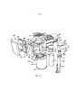
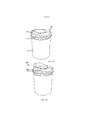
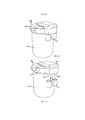
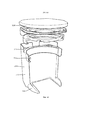
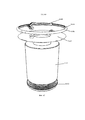
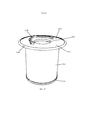
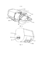
Система обработки воды местного применения согласно одному варианту осуществления данного изобретения показана на фиг. 1-10, в общем, под позицией 10.A topical water treatment system according to one embodiment of the present invention is shown in FIG. 1-10, in general, under
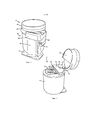
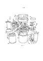
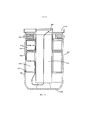
Вариант осуществления по фиг. 1-10 обеспечивает СОВ основным корпусом 12, который является быстро и легко отделяемым от основного участка 14. Это позволяет потребителю снимать основной корпус 12 с основного участка 14, который обычно устанавливают в особенно труднодоступном месте, например, под раковиной, и для целей обслуживания, перемещают в более благоприятное место.The embodiment of FIG. 1-10 provides an IDB
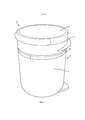
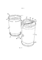
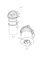
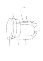
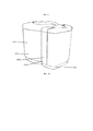
По фиг. 1 и 2 основной корпус 12 включает емкость 16 и закрывающую воду крышку 18. Основной участок 14, в общем, включает базовую опору 24, основание 26 базовой опоры и верхнюю часть 28 базовой опоры. С базой также шарнирно соединены роутер 35 воды и электронный блок 47 с крышкой 49 дисплея, так что для простоты удаления основного корпуса 12, роутер 35 воды и электронный блок 47, каждый, могут быть шарнирно переведены в открытое положение. По фиг. 3 емкость 16, в общем, является цилиндрической камерой с отверстием 30 на одном конце. Боковая стенка 32 емкости 16 включает верхний край 34, который образует отверстие 30. В иллюстрируемом варианте осуществления боковая стенка 32 включает углубление 36, продолжающееся по окружности емкости 16 непосредственно у верхнего края 34.According to FIG. 1 and 2, the
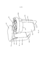
В иллюстрируемом варианте осуществления основание 26 базовой опоры прикреплено к нижнему краю 23 опорной стенки 24 и обеспечивает конструкцию для соединения основного участка 14 с монтажной поверхностью (не показано) и крепления основного корпуса 12. В одном варианте осуществления СОВ 10 может включать в себя основание 26 базовой опоры и, вместо соединения с самой базовой опорой 24 или другим элементом базового участка 14, может быть соединено с монтажной поверхностью. Как показано, базовая опора 24 имеет приблизительно ту же самую высоту, что и основной корпус 12, и включает верхний край 25, который выполнен с возможностью соединения с верхней частью 28 базовой опоры. Верхняя часть 28 базовой опоры включает нижнюю поверхность 31, которая располагается на верхнем крае 25 базовой опоры 24, первый шарнирный приемник 33 для приема шарнирно устанавливаемого роутера 35 воды, второй шарнирный приемник 37 для приема шарнирно устанавливаемого электронного блока 47, и защелкивающуюся крышку 49 дисплея. Базовая опора 24 может включать в себя выступ 21 для взаимного скрепления с отверстием 27, продолжающийся вверх от верхней части базовой опоры 28, или углубление на закрывающем воду боковом покрытии 18, для соответствующего размещения основного корпуса 12 на базовой части 14.In the illustrated embodiment, the
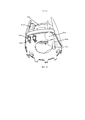
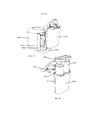
Как показано на фиг. 3-6, роутер 35 воды образует два внутренних канала для направления воды в СОВ 10 и из него. Первый канал 51 обеспечивает жидкостное сообщение с помощью трубчатого выпускного шарнирного элемента 53 - на одном конце роутера 35, и с помощью выпускной утолщенной втулки 55 - околов середине роутера 35. Второй канал 57 обеспечивает жидкостное сообщение с помощью трубчатого впускного шарнирного элемента 59 - на одном конце роутера 35, и с помощью впускной утолщенной втулки 61 - на противоположном конце. Трубчатые шарнирные элементы 53 и 59 соединяют с первым шарнирным приемником 33, например, защелкивающимся креплением на противоположных его сторонах, а также скрепляют с роутером 35 воды, так что роутер воды может поворачиваться относительно шарнирных элементов 53, 59 между первым положением (или "закрыто"), показанным на фиг. 3, и вторым положением (или "открыто"), показанным на фиг.4-6. Для закрытия и изоляции роутера 35 воды над ним может быть установлена крышка 67 роутера воды. Для подключения СОВ к концам обычных шлангов и трубопроводов (не показано), к концам трубных шарнирных элементов 53 и 59 может быть подсоединено множество трубных соединителей, например, трубный соединитель 65, показанный на фиг. 7. Альтернативный трубный соединитель 69, показанный на фиг. 2, может включать в себя дополнительное отверстие 71, или отверстия для обеспечения жидкостного сообщения с впускными или выпускными трубчатыми шарнирами, выполненными с возможностью простого соединения с расположенным далее устройством, например, устройством выдачи напитка, или предыдущим устройством, например, другой ступенью очистки воды или устройством.As shown in FIG. 3-6, the
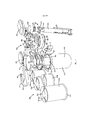
В одном варианте осуществления для шарнирного соединения электронного блока 47 с верхней частью 28 базовой опоры, электронный блок 47 включает шарнирный узел 73, который продолжается во втором шарнирном приемнике 37 в верхней части 28 базовой опоры, так что электронный блок 47 может поворачиваться между первым положением ("закрыто"), показанным на фиг. 2, и вторым положением ("открыто"), показанным на фиг3-6. Как показано на фиг. 7, в одном варианте осуществления электронный блок 47 включает внутреннюю полость 75, для размещения множества электронных компонентов, которые могут быть утилизированы СОВ 10, например, источники энергопитания, датчики, контроллеры и соответствующие схемы. В одном варианте осуществления СОВ может использовать индуктивно связанную балластную схему, например, которая раскрыта в патенте США, U.S. Patent 6,825.620 (содержание которого приведено здесь посредством ссылки), для питания одного, или более компонентов, включая лампу УФ для модуля УФ дезинфекции. Индуктивно связанная балластная схема обеспечивает связь между источником питания и нагрузкой без непосредственной электрической связи, например, проводов или спаянной электропроводки, и без подвижной электросвязи, например, разъемов или других соединительных элементов. Балластная схема - включающая в себя первичную обмотку - может быть размещена в электронном блоке 47. В показанном на фиг. 7 варианте осуществления балластная схема для питания лампы УФ представлена схематично, в виде цилиндрического диска 81, который помещен в электронный блок 47.In one embodiment, for swiveling the
Крышка 49 дисплея подобрана по размеру с возможностью соединения с электронным блоком 47, например, защелкивающимся креплением в электронном блоке 47, или резьбой, или другим способом скрепления. Крышка 49 дисплея может вмешать в себя большое разнообразие дисплеев, например, ЖК-дисплей (LCD display), или любой другой традиционный дисплей на боковом краю 83 крышки 49 дисплея, для отображения множества характеристик о СОВ 10, например, текущее состояние фильтра, энергоснабжения, и качества воды. В одном варианте осуществления, представленном на фиг. 10, крышка 49 дисплея может включать в себя полусферическую верхнюю поверхность 85, которая может быть прозрачной, или включать в себя прозрачный участок, для включения дисплея непосредственно на верхней поверхности 85, или под ней. В одном варианте осуществления крышка 49 дисплея может поворачиваться внутри электронного блока 47, что позволяет пользователю регулировать направление показа дисплея.The
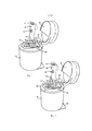
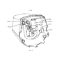
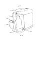
Для закрывания емкости 16 и обеспечения впускного и выпускного отверстий для воды, закрывающая воду крышка 18 крепится над верхним краем 34 емкости 16. Как показано, закрывающая воду крышка 18 включает пару скользящих заглушек 38, 39, расположенных на противоположных сторонах крышки 18. Скользящие заглушки 38, 39 могут быть активированы перемещением ручки 40, для скольжения между закрытым положением, показанным на фиг. 4, промежуточным положением, показанным на фиг. 5-6, и открытым положением, показанным на фиг. 9. Скользящие заглушки 38, 39, каждая, включают в себя пару ножек 41, которые установлены с возможностью скольжения в пазах 43 закрывающей воду крышки 18. Теперь, по фиг. 7, ручка 40 включает пару расположенных на противоположных ее сторонах кулачков 42, 44. Кулачки 42, 44 входят в выемки 46, 48 в закрывающей воду крышке 18, и удерживаются на месте защелками 50. Кулачки 42, 44 соединены со скользящими заглушками 38, 39 посредством скользящих звеньев 52, 54, 56 и 58. В частности, выступ 60 на одном конце скользящего звена 52 фиксируется в удлиненном пазу 70 на одной стороне скользящей заглушки 39, а выступ 62, на противоположном конце скользящего звена 52, фиксируется в отверстии кулачка 42. Подобным образом, выступ 66 на одном конце скользящего звена 54 фиксируется в удлиненном пазе 72 скользящей заглушки 38, а выступ 64, на противоположном конце скользящего звена 54, фиксируется в отверстии на задней поверхности (не показано) кулачка 42. Скользящие звенья 56, 58 соединяются подобным образом с кулачком 44 и удлиненными пазами 76, 78 скользящих заглушек 38, 39. Данная конструкция заставляет скользящие звенья 52, 54, 56 и 58, при повороте ручки 40 и кулачков 42, 44 в положение "закрыто", втягивать скользящие заглушки 38, 39 в закрытое положение, и далее, при повороте ручки 40 и кулачков 42, 44 в положение "открыто", заставляет скользящие звенья вытягивать скользящие заглушки 38, 39 в открытое положение. Удлиненная форма пазов 70, 72, 76 и 78 допускает некоторое перемещение скользящих звеньев 52, 54, 56 и 58 в пазах, так что скользящие заглушки 38, 39 остаются в закрытом положении, пока ручка не повернется в положение "открыто" околоза 90°. Таким образом, при повороте ручки в положение "открыто" только до 90°, ручка 40 может быть использована для поднятия полного основного корпуса 12, как показано на фиг. 5 и 6.For closing the
Закрывающая воду крышка 18 дополнительно обеспечивает доступ к отверстиям внутри емкости 16. В одном варианте осуществления, показанном на фиг. 4, закрывающая воду крышка 18 включает впускное отверстие 80, для подачи в емкость 16 неочищенной воды, и выпускное отверстие 82, для очищенной воды, находящейся в емкости 16. При повороте роутера 35 воды в первое (т.е., закрытое) положение впускную втулку 61 вводят во впускное отверстие 80 на закрывающей воду крышке 18, а выпускную втулку 55 вводят в выпускное отверстие 82 на закрывающей воду крышке 18, чтобы допустить впуск текучей среды через трубчатый впускной шарнирный элемент 59, впускной канал 57 и впускную втулку 61 в СОВ 10, и допустить выпуск текучей среды из СОВ 10 через выпускную втулку 55, выпускной канал 51 и через трубчатый выпускной шарнирный элемент 53. Дополнительно закрывающая воду крышка 18 включает входное отверстие 84 для введения и удаления лампы 122 УФ (описанной подробно ниже). На фиг.8 показана лампа 122 УФ, частично выдвинутая из закрывающей воду крышки 18 через входное отверстию 84.The water-closing
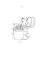
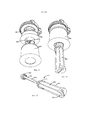
Для очистки пропускаемой через устройство воды, СОВ 10 может быть снабжена множеством фильтрующих и/или дезинфицирующих устройств. В одном варианте осуществления СОВ 10 включает первичный фильтрующий блок 100 и дезинфицирующий блок 120, которые выполнены, по размеру, в соответствии с внутренним пространством емкости 16, так что вода, перед выходом ее из СОВ 10 в очищенном виде, может быть направлена через каждый их блоков 100, 120, для удаления загрязняющих веществ и блокирования микроорганизмов.For cleaning the water passed through the device,
В одном варианте осуществления фильтрующий блок 100 представлен цилиндрическим угольным блочным фильтром, дезинфицирующий блок 120 представлен блоком лампы УФ, который расположен в центре цилиндрического угольного блока, подобный устройству, раскрытому в патенте США U.S. Patent 6, 451, 202 to Kuennen, описание которого приведено здесь посредством ссылки. В иллюстрируемом варианте осуществления фильтрующий блок 100 включает фильтрующий материал 102 и пару крышек 104, 106. В одном варианте осуществления крышки 104, 106 могут быть выполнены из упругого материала, например, упругого эластомера или резины, который, при закрытой над отверстием 30 емкости 16 крышке 18, создает герметичную изоляцию между закрывающей воду крышкой 18 и дном емкости 16. Фильтрующий материал 102 может иметь множество конфигураций и может быть выполнен из множества материалов для фильтрации из воды необходимого количества или вида твердых частиц. В одном варианте осуществления фильтрующий материал 102 представлен угольным блочным фильтром, например, угольный блочный фильтр, раскрытый в патенте США U.S. Patent 6, 368, 504 to Kuennen, содержание которого приведено здесь посредством ссылки, причем угольный блок включает угольные частицы и связующее вещество, а угольные частицы имеют диаметр в диапазоне от около 60 до около 80 мк, и при этом распределение в нем частиц угля по размеру более около 140 меш, составляет не более около 10% по весу, и по размеру менее около 500 меш, не более около 10% по весу от общего веса угольных частиц. Альтернативно фильтрующий материал 102 может быть обеспечен разным угольным составом. В еще одной альтернативе фильтрующим материалом 102 может быть бумажный фильтр, например, фильтр из гофрированной бумаги, или фильтр из гофрированной ткани, или материал из гранулированной смолы, или фильтрующий материал другого вида, например, фильтр с мембраной из полых волокон. В одном варианте осуществления могут быть обеспечены два, или более видов фильтрующего материала, выполненного в виде слоев, с одним фильтрующим материалом, охватывающим, по меньшей мере, участок второго фильтрующего материала. Внешний фильтрующий слой может быть связан с внутренним фильтрующим слоем в виде унитарного заменяемого фильтрующего блока, или может быть обеспечен в виде отдельного заменяемого цилиндра, который может быть установлен снаружи внутреннего слоя. Один конкретный вариант осуществления включает предварительный фильтр из гофрированной ткани (не показано), который охватывает угольный блок. В иллюстрируемом варианте осуществления верхний концевой колпачок 104 фильтрующего блока 100 включает фланец 108, который продолжается вверх и изолирует от воды закрывающую воду крышку 18, когда крышка 18 находится на месте. Фланец 108 расположен внутри водовпускного отверстия 80 в закрывающей воду крышке 18, вынуждая, тем самым, входящую в емкость воду, перед радиальным стеканием внутрь через фильтрующий материал 102, обтекать снаружи фильтрующий материал 102 между ним и боковой стенкой 32. В одном варианте осуществления СОВ 10 может быть снабжено только фильтрующим блоком 100, без дезинфицирующего блока 120. В данном варианте осуществления протекающая через фильтрующий материал 102 вода течет радиально внутрь него, в полое пространство в центре фильтрующего материала 102, и выпускается через выпускное отверстие 82.In one embodiment, the
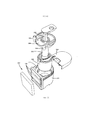
В иллюстрируемом варианте осуществления предпочтительным дезинфицирующим блоком 120 является реактор УФ-излучения (UV). Известно множество реакторов УФ-излучения для применения в очистке воды, и которые могут быть применены в СОВ 10, включая реактор УФ-излучения, раскрытый в патенте США U.S. Patent 6, 451, 202 to Kuennen. Блок УФ обеспечивает УФ-излучение, необходимое для блокирования многих микроорганизмов, проходящих через СОВ 10. Иллюстрируемый на фиг. 7 реактор УФ-излучения 120 включает лампу УФ 122, кварцевую трубку 124, перегородку 126 реактора УФ-излучения, гнездо 127 перегородки, дополнительное электронное устройство 128, корпус 129 реактора и крышку 130 лампы УФ.In the illustrated embodiment, the
Лампа УФ 122 включает две расположенные рядом излучающие лампы 132, которые электрически связаны с дополнительным электронным устройством - включающим в себя вторичную обмотку - так что лампа может быть индуктивно обеспечена энергией через электрическое соединение между первичной обмоткой 81, размещенной внутри электронного блока 47, расположенного над лампой УФ, и вторичной обмоткой 128. Лампа УФ выполнена с возможностью индивидуальной, от остальной части реактора УФ-излучения и от СОВ 10, замены, введением и удалением ее через входное отверстие 84 в закрывающей воду крышке 18. После ввода лампы 122, вторичное электронное устройство 128 лампы УФ закрепляют в выемке 134 закрывающей воду крышки 18 и закрывают заглушкой 130 UV лампы, которую можно защелкнуть на месте внутри выемки 134. Остальные компоненты закрепляют во внутреннем пространстве отверстия 135 в цилиндрическом фильтрующем материале 102.The
Корпус 129 реактора УФ-излучения является, в общем, цилиндрическим с диаметром, несколько меньшим диаметра отверстия 135 фильтрующего материала 102, поэтому корпус реактора установлен внутри отверстия 135. Как показано, корпус 129 реактора включает пару лапок 140, которые продолжаются наружу от верхнего края корпуса 129. Для обеспечения выравнивания блока УФ-излучения лапки 140 входят в зацепление с гнездом 127 перегородки. Для обеспечения впуска воды к блоку 120 УФ-излучения, корпус 129 реактора дополнительно включает выемку 142 в нижнем крае корпуса 129. В зависимости от требуемого объема пропускаемой через реактор УФ-излучения воды, размер впуска может быть изменен. Разделительные перегородки 126, в общем, включают основание 144 и три ножки 146, продолжающиеся вверх от основания 144, которые работают в качестве разделителей между корпусом 129 реактора и кварцевой оболочкой 124, для обеспечения многокамерного пути потока воды. Как показано, конец каждой ножки 146 включает круглую головку 148, которая точно соответствует подобно выполненному соединительному отверстию 150 в гнезде 127 перегородки, для удержания на нем перегородки 126. Кварцевая оболочка. 124 установлена между стойками перегородки 126 и окружает лампы УФ 132, когда ламповый блок 122 введен, в то же время, передавая УФ свет в путь потока между кварцевой трубкой 124 и корпусом 129, когда УФ свет включен. Гнездо 127 перегородки находится на верхнем концевом колпачке 104 фильтрующего блока 100 и включает выпускное отверстие 152, которое совпадает с выпускным отверстием 82 в закрывающей воду крышке 18, с допущением выхода воды из блока УФ-излучения, и окончательно, после ее очистки, из СОВ 10.The UV housing of the
При работе, водный поток через фильтрующий материал 102 поступает в блок реактора УФ-излучения по выемке 142 в нижней части корпуса 129 реактора и поднимается по зазору между корпусом 129 и кварцевой оболочкой 123, где УФ-излучение уничтожает в воде микроорганизмы при ее протекании через множество камер, разделенных перегородками 126, представленными в данном варианте осуществления тремя отделениями, и, наконец, выпускается через выпускное отверстие 152 основного корпуса. Вода может поступать в блок УФ-излучения через выемку 142 в корпусе 129 и течь в первую камеру 121. Далее вода поднимается по первой камере 121 и выходит через отверстия 123 в верхней части стойки 146, чтобы войти во вторую камеру 125, и затем выпускается вниз и выходит через отверстия (не показано) в нижней части следующей стойки 146, чтобы войти в третью камеру 133. Наконец, вода выходит из реактора УФ-излучения по выпускному участку 152.During operation, the water flow through the
Несмотря на то, что иллюстрируемый вариант осуществления включает реактор УФ-излучения, могут быть применены другие дезинфицирующие блоки, например, хлорные, бромированные полистироловые гранулы, или другая контактная бактерицидная техника (производимая и распространяемая HaloSourse, Inc., of Bothell, Washington), электропозитивный нановолокнистый фильтрующий материал (производимый и распространяемый Ahlstrom Corp. Of Helsinki, Finland), например, как показано на фиг. 25 в связи со вторым вариантом осуществления, ультрафильтрация или другой вид блока дезинфицирующей очистки.Although the illustrated embodiment includes a UV irradiation reactor, other disinfecting units may be used, for example, chlorine, brominated polystyrene beads, or other bactericidal contact techniques (manufactured and distributed by HaloSourse, Inc., of Bothell, Washington), the electropositive nanofiber filter media (manufactured and distributed by Ahlstrom Corp. Of Helsinki, Finland), for example, as shown in FIG. 25 in connection with a second embodiment, ultrafiltration or another type of disinfectant cleaning unit.
В одном варианте осуществления фильтрующий блок 100 и дезинфицирующий блок 120 могут включать, каждый, маркировочную схему (не показано), установленную или закрепленную внутри блока. Маркировочную схему используют для хранения информации о работе конкретного фильтра или блока, и регистрации параметров, касающихся данной работы. Датчики в электронном блоке 47 обеспечивают с помощью индукции энергопитание и связь с маркировочными схемами для получения подробностей, касающихся хранимой информации и зарегистрированных параметров. Полученные датчиками параметры могут быть отображены на крышке 49 дисплея. Они могут быть также использованы для регулирования работы средств управления СОВ с целью выдачи характеристик узла.In one embodiment, the
На фиг. 3-6 показано простое удаление основного корпуса 12 из основного участка 14. Как показано на фиг. З, для открывания роутера 35 воды и закрывающей воду крышки 18 дисплея, электронный блок 47 и крышка 49 дисплея могут быть шарнирно повернуты в открытое положение. Затем роутер 35 воды может быть повернут в открытое положение с отделением впуска 61 и выпуска 55 воды от основного корпуса 12, и основной корпус 12 может быть поднят за ручку из базового участка 14. В таком положении, с ручкой, повернутой до положения приблизительно 90°, основной корпус 12 может быть перенесен в удобное место для техобслуживания и/или замены фильтра. В таком положении лампа 122 УФ может быть удалена или заменена. Наконец, когда ручка 40 повернута за отметку 90° (как на фиг. 9), скользящие заглушки 38 и 39 открываются и закрывающая воду крышка 18 может быть удалена с обеспечением доступа к фильтрующему блоку 100 и остальному из дезинфицирующего блока 120.FIG. 3-6, a simple removal of the
ВТОРОЙ ВАРИАНТ ОСУЩЕСТВЛЕНИЯSECOND OPTION OF IMPLEMENTATION
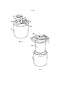
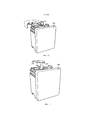
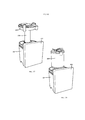
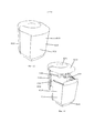
Согласно второму варианту осуществления данного изобретения СОВ представлено на фиг. 11-26 и обозначено, в общем, позицией 200.According to the second embodiment of the present invention, the SOW is shown in FIG. 11-26 and is indicated, in general, by the
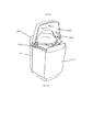
Вариант осуществления, представленный на фиг. 11-26, обеспечивает большой эстетичный дисплей 202, который соединен с основным корпусом 203 и может быть выполнен, по желанию, с множеством дисплейных модификаций. Как представлено на фиг. 11, дисплей 202 включает переднюю панель 204, которая закрывает полностью переднюю поверхность устройства СОВ 200. Передняя панель 204 образует наружную поверхность электронного "блока", более подробно представленного на фиг. 21, который вмещает в себя, между передней панелью 204 и задней пластиной 208, один, или более съемных электронных "модулей" 206. Передняя панель 204 обеспечивает экран дисплея для отображения множества информации о СОВ 200 и компонентах внутри СОВ 200. В одном варианте осуществления передняя панель 204 дисплея выполнена полупрозрачной или прозрачной, так что через переднюю панель 204 дисплея виден один, или более светодиодных дисплеев на индивидуальных электронных модулях 206. В другом варианте осуществления передняя панель дисплея сама может служить в качестве экрана, например, (LCD экрана) экрана дисплея на жидких кристаллах, экрана с печатанием электронными чернилами, или другим альтернативным дисплеем. В одном варианте осуществления передняя панель 204 включает периферический край 210, который установлен на периферический край 212 задней пластины 208 и входит в зацепление с передней стенкой 220 основного корпуса 203, рассмотренного ниже.The embodiment shown in FIG. 11-26, provides a large
Электронные модули 206 могут быть любого требуемого размера или формы, несмотря на то, что модули 206, представленные в иллюстрируемом варианте осуществления, имеют стандартную ширину, так что они защелкиваются соответственно с рядом первых выступов 214 на первой стороне задней пластины 208 и рядом вторых выступов 216 на противоположной стороне задней пластины 208. Конечно, возможны другие способы соединения. Модули 206 могут также включать в себя электронную схему и средство управления для одной, или более из множества модификаций, например, датчики, источники энергопитания и аварийное аккумуляторное питание. Как отмечено выше, каждый электронный модуль может также включать в себя элементы отображения, например, для передачи изображения через полупрозрачную или прозрачную переднюю поверхность 204. В одном варианте осуществления пластина 208 включает встроенный электронный адаптер, так что каждый электронный модуль 206 может быть электрически соединен с СОВ 200 путем подсоединения на пластине 208. Пластина 208 может включать в себя клеммные коробки (не показано), или другой вид электрического подключения электронных модулей 206 к ней, с возможностью удаления. Таким образом, при желании, изготовителем или любым конкретным потребителем могут быть встроены различные электронные блоки 206, удовлетворяющие особенностям СОВ 200. Пластина 208 может дополнительно включать в себя один, или более удлиненных пазов 218, продолжающихся по ней. Чтобы помочь датчикам в электронных модулях 206 эффективно обеспечивать связь с маркировочными схемами, пазы 218 устанавливают в соответствии с маркировочными схемами, например, интегральными схемами радиочастотной идентификации (RFID), расположенными внутри компонентов основного корпуса. Для обеспечения возможности эффективной передачи датчиками в электронных модулях 206 информации о течении, давлении, температуре и других атрибутах, пазы 218 выравнивают в соответствии с впускным и выпускным проводящими путями 242, 244, содержащимися внутри камеры 222 давления СОВ.The
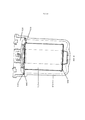
Основной корпус 203, в общем, включает лицевой участок 220 корпуса, камеру 222 давления, задний участок 224 корпуса, верхнюю крышку 226, крышку 228 роутера воды, главный фильтрующий блок 230 и дезинфицирующий модуль 232. Камера 222 давления работает в качестве структурного корпуса для СОВ 200. По фиг. 14, камера 222 давления является, в общем, цилиндрической емкостью с боковой стенкой 234 и верхним краем 236, который образует отверстие 238. Однако передний участок 240 камеры 222 давления является, в общем, плоским, и включает два изолированных, интегрально выполненных трубчатых проводящих пути 242 и 244, для направления воды внутрь СОВ 200 и из нее через дно устройства. По фиг. 14 и 22, первый трубчатый проводящий путь 242 является впуском неочищенной воды, который включает вход 246 в нижней части камеры 222 давления и выпуск 248 в верхней части камеры 222 давления. Второй трубчатый проводящий путь 244 является выпуском очищенной воды, который включает вход 250 в верхней части резервуара 222 давления и выпуск 252 в нижней части камеры 222 давления. Трубчатые проводящие пути, оба, расширяются в виде раструба наружу около верхнего края 236 камеры 222 давления, с образованием приемных гнезд для участков впуска и выпуска крышки 228 роутера воды (рассмотрено более подробно ниже). В одном варианте осуществления передний участок 240 выполнен из пластического материала, так что любые маркировочные схемы, расположенные внутри камеры 222 давления, могут обеспечивать связь с датчиками, или другой электроникой, расположенными в одном из электронных модулей 206. В другом варианте осуществления вся камера 222 давления интегрально выполнена из одного и того же пластического материала. Лицевой участок 220 корпуса и верхняя закрывающая пластина 241 образуют стыковое соединение между камерой 222 давления и дисплеем 202. В частности, верхняя закрывающая пластина 241 соединяется с передним участком 240 камеры 222 давления около верхнего конца 236, а лицевой участок 220 корпуса соединен с верхней закрывающей пластиной 241 и передним участком 240 камеры 222 давления. Передняя поверхность 256 лицевого участка 220 корпуса соединяется с задней пластиной 208 дисплея 202. В одном варианте осуществления лицевой участок 220 корпуса выполнен из пластического материала и включает один, или более пазов 258, продолжающихся по переднему участку 240 корпуса, с возможностью обеспечения связи через передний участок 240 корпуса между электронными модулями 206 и маркировочными схемами в камере 222 давления, и возможностью обеспечения связи между электронными модулями 206 и компонентами внутри впускного и выпускного проводящих путей 242, 244, содержащимися внутри камеры 222 давления. Пазы 258 в лицевом участке 220 корпуса могут быть выровнены с пазами 218 в задней пластине 208 дисплея 202.The
Задний участок 224 корпуса включает, в общем, боковую стенку 225 U-образной формы, которая выполнена по размерам с возможностью приема камеры 222 давления. Задний участок корпуса включает передний край 254, который входит в зацепление и соединяется с периферическим краем лицевого участка 220, с образованием эстетичной наружной поверхности СОВ 200. Задний участок 224 корпуса дополнительно включает нижнюю стенку 260 и верхний край 262. Нижняя стенка 260 включает первое отверстие 264, которое соответствует входу 246 трубы 242 впуска воды, и второе отверстие 266, которое соответствует выходу 252 трубы 244 выпуска воды. Таким образом, вода может быть незаметно направлена в СОВ 200, и из нее, через дно устройства. В одном варианте осуществления задний участок 224 корпуса включает желоб 268, который продолжается по всей боковой стенке 225 около верхнего края 262, с возможностью приема, за счет скольжения, верхней крышки 226.The
Как представлено, верхняя крышка 226, в общем, выполнена U-образной формы, соответствующей форме заднего участка 224 корпуса. Конечно, формы каждого из компонентов корпуса могут изменяться в зависимости от применения. Верхняя крышка 226 выполнена с возможностью удаления с СОВ 200, для обеспечения доступа к фильтрующему блоку 230 и дезинфицирующему блоку 232. Как показано на фиг. 23, верхняя крышка 226 включает верхнюю стенку 270 и боковую стенку 272. Боковая стенка 272 включает продолжающийся внутрь выступ 274 на внутренней поверхности, который взаимодействует с желобом 268 на заднем участке 224 корпуса, так что верхняя крышка 226 крепится, за счет скольжения, к заднему участку 224 корпуса. В одном варианте осуществления верхняя крышка 226 дополнительно включает пару L-образных фланцев 274, которые продолжаются вниз от верхней стенки 270 с возможностью приема, за счет скольжения, направляющего рельса 276. Направляющий рельс 276 включает пару ползунов 278, которые соответственно охватывают фланцы 274, с закреплением направляющего рельса 276 внутри верхней крышки 226. В одном варианте осуществления направляющий рельс 276 поддерживает основную электронику 280 для индуктивной балластной цепи, обсужденной выше в связи с первым вариантом осуществления. Основная электроника 280 может быть использована с индуктивным энергоснабжением вторичной обмотки, подключенной к нагрузке, например, лампе УФ внутри дезинфицирующего модуля 232. Дополнительно, верхняя крышка 226 включает защелку 282, установленную на направляющем рельсе 276, для зацепления верхнего края задней пластины 208, с удержанием на месте верхней крышки 226 на установке 200.As shown, the
В одном варианте осуществления крышка 228 роутера воды выполнена, в общем, в виде кольцевой заглушки, которая монтируется в верхнем конце 236 резервуара 222 давления. В частности, крышка 228 роутера воды включает конусную боковую стенку 290, которая расклинивается на верхнем конце 236 резервуара 222 давления с обеспечением неподвижной посадки. Для удаления крышки с устройства СОВ 200 от верхней поверхности 294 крышки 228 продолжаются две ручки 292. Для более легкого ввода и удаления обычной УФ-лампы 360 в одном варианте осуществления крышка 228 включает центральное отверстие 295, продолжающееся через крышку 228. В другом варианте осуществления, в котором СОВ 200 не включает возможный дезинфицирующий модуль 232, крышка 228 роутера воды, для изоляции отверстия 295, снабжена заглушкой 297. Заглушка 297 может соединяться с крышкой 228 с помощью соединения байонетного типа. Как показано на фиг.26, крышка включает впускную трубу 296 и выпускную трубу 298, продолжающиеся по боковой стенке 290. Впускная труба 296 включает отверстие (не показано) в нижнем конце, которое продолжается по боковой стенке крышки и выходит через дно крышки 228 внутри резервуара 222 давления. Впускная труба 296, таким образом, направляет поступающую в СОВ 200 воду по впускной трубе 242 через крышку 228 и в резервуар 222 давления. Выпускная труба 298 включает вход (не показано) внутри центрального отверстия 295 крышки 228, причем центральный участок 302 продолжается по крышке 228, и пару выходов 304, 306. Верхний выход 304 направлен вверх устройства СОВ, для направления очищенной воды через верхнюю часть устройства 200, а нижний выход 306 выровнен со выпускной трубой 244, выполненной в резервуаре 222 давления, для направления очищенной воды на выпуск через нижнюю часть устройства СОВ. Для изолирования выхода 304, 306, который не используют, может быть обеспечена заглушка (не показано), или альтернативно, внутренний клапан.In one embodiment, the
Для очистки пропускаемой воды СОВ 200 может быть снабжена множеством фильтрующих и/или дезинфицирующих устройств. По одному варианту осуществления СОВ 200 включает основной фильтрующий блок 230 и дезинфицирующий блок 232, которые выполнены по размеру, в соответствии с внутренним пространством резервуара 222 давления, так что вода может быть пропущена через каждый из блоков 230, 232, для удаления загрязняющих веществ и блокирования микроорганизмов перед выходом из СОВ 200 в виде очищенной воды.For cleaning the water that is passed through, the
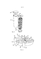
В одном варианте осуществления основной фильтрующий блок 230 и дезинфицирующий блок 232 являются, по существу, теми же, что и основной фильтрующий блок 100 и дезинфицирующий блок 120 первого варианта осуществления, поскольку основным фильтрующим блоком 230 является цилиндрический угольный блочный фильтр, а дезинфицирующим блоком 232 является УФ ламповый блок, который расположен в центре цилиндрического угольного блока. В иллюстрируемом варианте осуществления, показанном на фиг. 19, фильтрующий блок 230 включает возможный предварительный фильтр 310, имеющий пару крышек 312, 314 и внутренний фильтрующий материал 320, имеющий пару концевых колпачков 322, 324. В одном варианте осуществления концевые колпачки 312, 314, 322 и 324 могут быть выполнены, каждый, из упругого материала, например, упругого эластомера или резины, который обеспечивает герметичную изоляцию между закрывающей воду крышкой 228 и дном емкостного резервуара 222 давления, когда закрывающая воду крышка 228 закрыта над отверстием 238 камеры 222 давления. Дополнительно, верхний концевой колпачок 322 внутреннего фильтрующего материала 320 может включать интегральную раскладную ручку 330. В иллюстрируемом варианте осуществления ручка 330 включает пару противоположных клапанов 333, которые выполнены как одно целое с верхним концевым колпачком 322 и соединены с верхним концевым колпачком 330 в защелке 334. Когда крышка 228 роутера воды удалена с резервуара 222 давления, клапаны 333 складывают, для более легкого вытягивания фильтрующего материала из резервуара 222 давления. Дополнительно, верхний концевой колпачок 322 может включать защелку 336, которая соответственно сопрягается с канавкой 338 в верхнем концевом колпачке 312 возможного предварительного фильтра 310 и канавкой (не показано) на емкости 222 давления, что обеспечивает ключ ориентации с гарантией совмещения маркировочных схем, которые могут присутствовать на любом, или обоих фильтрующих элементах.In one embodiment, the
Как и в первом варианте осуществления, фильтрующие материалы 310, 320 могут иметь много конфигураций и могут быть выполнены из множества материалов, для фильтрации из воды требуемого количества, или вида загрязняющих веществ. В одном варианте осуществления внутренним фильтрующим материалом 320 является угольный блочный фильтр, например, угольный блочный фильтр, раскрытый в патенте США U.S. Patent 6,368,504 to Kuennen, в котором угольный блок включает частицы активированного угля и связующее вещество, а частицы угля имеют средний размер, изменяющийся в диапазоне от около 60 до около 80 мк, и в котором распределение частиц по размеру представлено, по весу, не более около 10% частиц более около 140 меш и не более около 10% частиц менее около 500 меш. Альтернативно, фильтрующий материал 320 может быть представлен другой угольной смесью. В еще одной альтернативе фильтрующий материал 320 может быть бумажным фильтром, например, фильтром из гофрированной бумаги, или фильтром из гофрированной ткани, или фильтром из гранулированной смолы, или фильтрующим материалом другого вида, например, фильтром с мембраной из полых волокон. В одном варианте осуществления предварительный фильтр 310 для удаления из воды более крупных частиц представлен бумажным фильтром, но предварительный фильтр 310 может быть представлен множеством фильтрующих материалов разного вида. В другом варианте осуществления или предварительный фильтр 310, или внутренний фильтр 320 может включать в себя два, или более видов фильтрующего материала в послойном исполнении, с одним фильтрующим материалом, охватывающим снаружи, по меньшей мере, участок второго фильтрующего материала. Наружный фильтрующий слой может быть связан с внутренним фильтрующим слоем в виде одного цельного сменного фильтрующего блока, или он может быть обеспечен в виде отдельного сменного цилиндра, который может быть "одет" снаружи на внутренний фильтрующий материал 320, или предварительный фильтр 310. В иллюстрируемом варианте осуществления верхний концевой колпачок 322 внутреннего фильтрующего материала 320 включает верхний фланец 340, который продолжается вверх и изолирует от закрывающей воду крышки 228. Фланец 340 расположен внутри впуска воды трубы 296, вынуждая поступающую в камеру 222 давления воду, до протекания радиально вверх через предварительный фильтр 310 и внутренний фильтр 320, течь обратно снаружи возможного предварительного фильтра 310, между предварительным фильтром 310 и боковой стенкой 234 камеры 222 давления. В одном варианте осуществления СОВ 200 может быть обеспечена лишь фильтрующим блоком 230, и без дезинфицирующего блока 232 или предварительного фильтра 310. В данном варианте осуществления поступающая через внутренний фильтрующий материал 320 вода течет радиально вверх через фильтрующий материал 320, в полое пространство в центре фильтрующего материала 320 и выходит через выпускную трубу 298.As in the first embodiment, the
В иллюстрируемом примере возможным дезинфицирующим блоком является реактор УФ-излучения (UV), и по существу с теми же самыми функциями, что и реактор УФ-излучения, описанный выше в связи с первым вариантом осуществления. Как показано на фиг. 24, реактор 232 УФ-излучения включает УФ лампу 360, кварцевую трубу 362, перегородку 366 реактора УФ-излучения, гнездо 368 перегородки, вторичный электронные элементы 370, корпус 372 реактора и крышку 374 лампы УФ.In the illustrated example, a possible disinfecting unit is a UV irradiation reactor (UV), and with substantially the same functions as the UV irradiation reactor described above in connection with the first embodiment. As shown in FIG. 24, the
УФ лампа 360 включает две расположенные рядом излучающие лампы 376, которые электрически соединены с дополнительной электроникой - включающей в себя вторичную обмотку - так что лампа может быть индуктивно обеспечена энергией через электрическое соединение между основной электроникой 280, размещенной внутри верхней крышки 226, расположенной над лампой УФ, и дополнительной электроникой 370. Лампа УФ выполнена с возможностью замены отдельно от остальной части реактора УФ-излучения, и от СОВ 200, введением и удалением УФ лампы 360 через отверстие 295 доступа в закрывающей воду крышке 228. При введении лампы 360 дополнительную электронику 370 лампы УФ устанавливают над центральным отверстием 295 в закрывающей воду крышке 228 и закрывают крышкой 374 лампы УФ, которая может закрепляться на месте внутри выемки 295 защелкиванием устройства байонетного типа. Остальные компоненты закрепляют внутри отверстия внутреннего фильтрующего материала 320, а в одном варианте осуществления гнездо 368 перегородки включает лапки, которые взаимодействуют, посредством устройства байонетного типа, с пазом 373 в нижнем участке центрального отверстия 295. Данное соединение обеспечивает возможность удаления остальных компонентов УФ блока, когда крышка 228 роутера воды удалена. При работе протекающая через фильтрующий материал 320 вода течет в блок реактора УФ-излучения и вытекает из основного корпуса через крышку 228 и выпускную трубу 298. Как отмечено выше, вместо реактора УФ-излучения может быть применено большое разнообразие альтернативных дезинфицирующих модулей. На фиг. 25 представлен один альтернативный вариант осуществления, в котором дезинфицирующим модулем является электропозитивный нановолокнистый фильтрующий материал 390 с концевыми колпачками 392, 394.The
Как в первом варианте осуществления, фильтрующий блок 230 и дезинфицирующий блок 232 могут, каждый, включать в себя маркировочную схему, соединенную или установленную внутри блока. Например, как показано на фиг. 19, маркировочная схема 380 может быть введена в выемку 382 в стенке внутреннего фильтрующего материала 320. Маркировочные схемы используют для хранения информации о конкретном применяемом фильтре или блоке и регистрации параметров, касающихся данного применения. Датчики внутри электронных модулей 206 обеспечивают индуктивную энергию и связь с маркировочными схемами для получения подробностей, относящихся к хранимой информации и снимаемых параметрах. Замеренные датчиками параметры могут быть отображены дисплеем 202 и/или использованы для регулирования рабочих параметров и управления устройством, с размещением каждого конкретного альтернативного компонента.As in the first embodiment, the
На фиг. 15-18 показано более простое удаление из СОВ 200 фильтрующего блока 230 и дезинфицирующего блока 232. На фиг. 15 показана верхняя крышка 226, удаленная с устройства 200 путем ее сдвижения, за счет скольжения, с задней части 224 корпуса. На фиг. 16 показано удаление УФ лампы 360 через центральное отверстие 295 в крышке 228 роутера воды. На фиг. 17 показано удаление крышки роутера воды по остальной части блока 232 реактора УФ-излучения. На фиг. 18 показано удаление фильтрующего блока 230 с помощью раскладной ручки 330.FIG. 15-18 illustrate a simpler removal of the
Фиг. 38-41 иллюстрируют модификацию второго варианта осуществления, которая в целом обозначена позицией 500, причем задняя часть 224 корпуса, для обеспечения возможности более легкого удаления камеры 538 давления, устранена. Данная модификация, по существу, подобна второму варианту 200 осуществления, таким образом, внутренние компоненты не будут рассматриваться подробно. Достаточно сказать, что в данной модификации верхняя крышка 526, дисплей 502, закрывающая воду крышка 528, камера 538 давления, фильтрующий блок (не показан) и дезинфицирующий блок (не показан) по существу те же самые, что и во втором варианте 200 осуществления. Однако в данной модификации 500 дисплей 502 интегрально связан с монтажной тумбой 504, которая включает пару боковых стенок 506, пару ножек 508, верхний паз 510 в нижней части верхней крышки 526 и нижний паз 514 на внутренней поверхности тумбы 504. Дополнительно, для более легкого удаления из тумбы 504, камера 538 давления соответственно сопрягается с ручкой 515. В иллюстрируемом варианте осуществления ручка 515 включает вертикальный опорный элемент 516, нижний элемент 518, продолжающийся под углом от вертикального опорного элемента 516, и пару криволинейных держателей 520а-Ь, которые охватывают по бокам камеру 538 давления. Нижняя часть камеры давления может включать выемку 522, выполненную с возможностью приема нижнего элемента 518, так что нижний элемент 518 и держатели 520а-Ь могут защелкиваться, или иначе соединяться с камерой 538 давления. Камера 538 давления и ручка 515 могут быть соединены с тумбой 504 посредством скольжения верхнего участка камеры 538 давления и закрывающей воду крышкой 528 в верхнем пазу 510 и второго участка камеры 538 давления и держателей 520а-Ь в нижнем пазу 514. В данной модификации впуск и выпуск воды (не показано) могут быть встроены в тумбу 504, аналогично встраиванию впуска 242 и выпуска 244 по второму варианту осуществления.FIG. 38-41 illustrate a modification of the second embodiment, which is generally indicated with
На фиг. 42-59 показана другая модификация второго варианта осуществления. Данная модификация, обозначенная в общем позицией 600, включает электронный участок 610, который может быть отделен от участка 612 очистки. Данные компоненты этой модификации, по существу, подобны второму варианту 200 осуществления, включающему в себя электронный дисплей 602, камеру 638 давления, фильтрующий материал 611 и произвольное дезинфицирующее устройство (не показано).FIG. 42-59, another modification of the second embodiment is shown. This modification, generally designated 600, includes an
Как видно на фиг.43 и 44, электронный участок 610 включает дисплей 602, который, по существу, подобен электронным дисплеям 202 и 47 и, поэтому не будет рассматриваться подробно. Пара боковых стенок 614 и основание 616 связана с дисплеем 602. Боковые стенки 614 могут, каждая, включать паз 618, открытый к верхней части боковых стенок 614. Участок 612 очистки включает задний корпус 624, верхнюю крышку 626 и компоненты очистки, включающие в себя камеру 638 давления и фильтрующий и дезинфицирующий блоки, расположенные внутри камеры 638 давления. Как показано, верхняя крышка 626 включает шарнирный участок 630 с парой захватов 632, которые, для соединения двух участков 610, 612, входят в пазы 618 на электронном участке. При закрытом шарнирном участке 630, как на фиг.43, устройство закрывается защелкиванием. При открытом положении, как на фиг. 44, шарнирный участок 630 может быть использован в качестве ручки для отделения участка 612 очистки от электронного участка 610.43 and 44, the
На фиг. 45-48 показан альтернативный вариант осуществления фильтрующего блока 634 внутри СОВ 600. Альтернативная изоляция фильтра будет описана применительно к СОВ 600, однако, понятно, что альтернативная изоляция фильтра может быть использована со всеми вариантами осуществления СОВ, в частности, с СОВ 200. В иллюстрируемом варианте осуществления верхняя крышка 312 фильтрующего блока в СОВ 200 заменена альтернативным верхним колпачком 640. Верхний колпачок 640 крепится к верхнему концу фильтрующего материала 611 и включает, в общем, плоский центральный участок 642 и уплотнительный участок 644, продолжающийся по периметру центрального участка 642. Центральный участок 642 и уплотнительный участок 644 могут быть выполнены из разных материалов, которые могут быть получены совместным формованием, или скреплены друг с другом иначе, с образованием единой детали, или они могут быть выполнены из подобного единого куска материала, например, гибкого эластомера. В одном варианте осуществления центральный участок 642 выполнен из материала с большей, чем у уплотнительного участка 644, твердостью. Для приема дезинфицирующего устройства аналогичным отмеченной выше верхнему концевому колпачку крышке 312 способом, центральный участок 642 включает отверстие 643. Верхний колпачок 640 может дополнительно включать ручку 648, которая шарнирно крепится к верхней части верхнего колпачка 640, с обеспечением возможности удаления последнего. Как показано на фиг.46-48, уплотнительный участок 644 может иметь С-образное сечение, которое развальцовано наружу на внутренних концах 646. При вводе в камеру 638 давления уплотнительный участок 644 обеспечивает герметизацию со стороны стенки камеры 638 давления. Фильтрующий блок может также включать в себя нижний колпачок 650, подобную нижнему концевому колпачку 324, описанному выше, однако, так как верхний концевой колпачок 640 выполняет герметизацию со стороны боковой стенки камеры 638 давления, необходимости в выполнении изоляции со стороны стенки камеры 638 давления нижним колпачком.FIG. 45-48 shows an alternative implementation of the
Крышка 628 роутера воды, в общем, подобна крышке 228 роутера воды второго варианта осуществления, за исключением того, что передвинуты впускное отверстие (не показано) и выпускное отверстие 696 воды. В одном варианте осуществления крышка роутера воды теперь может включать в себя впускное отверстие воды, при этом впуск воды в камере давления перенесен в нижнюю часть камеры 638 давления. Выпуск 696 воды может быть перенесен на боковую стенку крышки 628 роутера воды. Следовательно, выходящая из СОВ 600 по выпускному соплу 645 на камере 638 давления вода, направляется из центрального отверстия 643 по выпускному отверстию 696 и выходит из выпускного сопла 645. Входящая через впускное отверстие в камеру 638 давления вода входит в пространство между камерой давления 638 и фильтрующим материалом 611 (и, возможно, произвольным предварительным фильтром), так что она может течь через фильтрующий материал 611, и далее, через произвольное дезинфицирующее устройство, как описано выше применительно к СОВ 200.The
Один вариант осуществления электронного участка 610 приведен на фиг. 49 (с удаленным дисплеем 602 и альтернативной задней панелью 617 участка очистки, связанной с боковыми стенками 614). Как показано, электронный участок 610 может включать в себя множество датчиков, например, датчик 652 температуры впускаемой воды, датчик 654 давления впускаемой воды, датчик 656 давления и датчик 658 температуры выпускаемой воды. Как показано на фиг. 49 и 50, входящая в СОВ 600 через впуск 660 вода, течет через петлю 651 передачи сигнала датчика, включающую в себя датчики 652, 654 впуска, перед ее направлением в нижнюю часть камеры 638 давления. Вытекающая из камеры 638 давления и через выпускное сопло 645 очищенная вода, течет в выпускную трубу 653 и по датчикам 656, 658, перед выходом из устройства через выпуск 662. Как отмечено выше, применительно к СОВ 200, каждый датчик может быть коммуникационно связан с одним, или более электронных блоков на электронном дисплее 622, например, с помощью технологии RFID (радиочастотной информации). С целью облегчения такой связи петля 651 и выпускная труба 653 расположены с возможностью размещения датчиков в непосредственной близости к дисплею 602 и любым электронным модулям на дисплее 602. В другом варианте осуществления, представленном на фиг. 50, СОВ 600 (или любой другой вариант осуществления СОВ) включает один, или более клапанов управления потоком воды в устройстве. Как показано, СОВ включает клапан 664 электронного управления и клапан 666 ручного управления. Электронный клапан 664 и ручной клапан 666 могут быть связаны с одним, или более модульными переключателями, которые заставляют клапаны 664 или 666 перекрывать поступающую в устройство воду в ответ на конкретный случай, например, отключение участка 604 очистки от электронного участка 602, удаление фильтра, или нарушение дезинфицирующего устройства. Клапаны 664, 666 способны прервать течение воды через впускной патрубок 667, который направляет воду в камеру 638 давления. Устройство 600 возможно может включать в себя один из клапанов 664, 666, или оба клапана. На фиг. 51 показан другой возможный вариант. В данном возможном варианте СОВ 600 включает вспомогательный механизм давления, например, обычный насос 668, соединенный со выпуском 662 воды (или альтернативно, с впуском 660), для прокачивания воды через СОВ 600. Вспомогательный насос 668 давления может быть полезным в ситуациях, когда подключенные к СОВ водопроводы не имеют давления (например, резервуар воды, соединенный с СОВ), или в ситуациях, когда водопроводы имеют недостаточное давление. В иллюстрируемом примере, со смонтированным на выпуске 662 воды насосе 662, насос может быть использован для "протягивания" воды через СОВ 600.One embodiment of the
Фиг. 52-53 иллюстрируют основание 670 с шарнирным креплением, для СОВ 600 (или любого другого варианта осуществления СОВ). В иллюстрируемом варианте основание с шарнирным креплением включает вертикальную панель 672, выполненную с возможностью крепления к вертикальной поверхности, например, к стенке, и горизонтальную панель 674, продолжающуюся от вертикальной панели, для поддержания СОВ 600. Как показано на фиг. 52-53, основная часть 616 базы СОВ 600 может быть так закреплена на основании 670 шарнирным креплением, что может поворачиваться между первым положением (показанным на фиг. 52), в котором виден дисплей 602, и вторым положением (показанным на фиг. 53), в котором участок 604 очистки может быть удален из электронного участка 602, путем поднятия ручки 630 с высвобождением участка 604 очистки.FIG. 52-53 illustrate the hinged
На фиг. 54-55 представлена другая модификация СОВ 600, в которой устройство выполнено с возможностью горизонтального шарнирного крепления. В данной модификации СОВ 600 включает подвеску 680 настенного крепления, продолжающуюся от задней стенки 682, которая соединена с электронным участком 610 и образует помещение для участка 612 очистки. Как показано на фиг. 54, участок 612 может быть продольно извлечен из электронного участка 610, благодаря скольжению, вытягиванием за шарнирную ручку 630. Как показано на фиг. 55, впуск 660 воды и выпуск 662 могут быть закрыты сводчатой крышкой 676, придающей эстетичный вид нижней стенке СОВ 600.FIG. 54-55 shows another modification of the
Фиг 56-59 представляют дополнительную модификацию СОВ 600, включающую в себя корпус 690 дополнительного фильтра. В одном варианте осуществления корпус 690 дополнительного фильтра включает передний участок 689, дополнительное основание 692 и боковую стенку 694, продолжающуюся от электронного участка 610. Корпус 690 дополнительного фильтра может быть выполнен для содержания одного, или более фильтров 695, 698, которые содержат фильтрующий материал для очистки конкретных загрязняющих веществ. Например, фильтры 695, 698 могут конкретно устранять мышьяк или жесткость воды, или нитраты, или могут наоборот вводить ингредиенты в воду, например, фториды. Как показано, корпус 690 дополнительного фильтра выполнен с возможностью приема двух фильтров 695, 698 в раздельные картриджи 687, размещенные в переднем участке 689 корпуса 690. Картриджи могут включать, каждый, верхний колпачок 685 для закрывания каждого картриджа 687, а крышка 683 может одеваться сверху на верхние колпачки 685 для соединения переднего участка 689 с задней стенкой 694. В другом варианте осуществления может быть применен, по желанию, одинарный фильтр, или дополнительные фильтры. Дополнительные фильтры 695, 698 соединены с основным фильтром 611, так что протекание воды через дополнительные фильтры 695, 698 также происходит через основной фильтр 611. В одном варианте осуществления дополнительные фильтры соединены параллельно друг с другом, так что течение воды через основной фильтр 611 может быть направлено через любой первый дополнительный фильтр 695, или второй дополнительный фильтр 698. В другом варианте осуществления дополнительные фильтры соединены последовательно, так что течение воды через основной фильтр 611 происходит как через первый дополнительный фильтр 695, так и через второй дополнительный фильтр 698. Корпус 690 дополнительного фильтра может быть расположен на любой стороне СОВ 600, так что он соединен с выпуском 662 воды ниже по ходу от основного фильтра 611, который является особенно предпочтительным в ситуациях, где он требуется для введения ингредиентов в очищенную воду, например, фторидов, или газирования. Альтернативно, корпус 690 дополнительного фильтра может быть соединен с впускным патрубком 667, или другим компонентом, расположенным выше по ходу от основного фильтра 611, который может быть предпочтительным при удалении из воды загрязняющих веществ до того, как они поступят в основной фильтр 611. В еще одном варианте осуществления дополнительные фильтры могут быть расположены по обеим сторонам основной СОВ 600 (добавление фильтров как выше, так и ниже по ходу). На фиг. 59 показана модификация СОВ 600, включающая выдачное устройство 700, соединенное с выпуском 662 СОВ 600. В данном варианте осуществления выдачное устройство 700 включает разливочную трубу 702. Разливочная труба 702 выполнена с возможностью выдачи воды в бутылку 706. Выдачной шланг 704 может находиться охлажденным в трубчатом контейнере 708. Для наливания в объекты в пределах досягаемости, без перемещения всей основной части СОВ 600, разливочная труба 702 может быть удалена из основания, путем вытягивания выданного шланга 704 из трубчатого контейнера 708. Безусловно, могут быть предусмотрены различные другие конструкции. В другом варианте осуществления выпуск из СОВ 600 (или любого другого варианта осуществления СОВ) может быть выполнен с возможностью подключения к конкретному устройству, ниже по ходу, например, посудомоечной машине, фонтанчику питьевой воды, или автомату прохладительных напитков.Figs 56-59 represent an additional modification of the
III. ТРЕТИЙ ВАРИАНТ ОСУЩЕСТВЛЕНИЯIii. THIRD VARIANT OF IMPLEMENTATION
СОВ по третьему варианту осуществления данного изобретения показано на фиг. 27-37 и, в общем, обозначено позицией 400.An IDN according to a third embodiment of the present invention is shown in FIG. 27-37 and, in general, indicated by the
Иллюстрируемый на фиг. 27-37 вариант осуществления обеспечивает система обработки воды, которое вмещает в себя один, или более легко удаляемых и взаимозаменяемых фильтрующих модулей 550. Данный вариант осуществления позволяет производителю, или потребителям адаптировать фильтрующие компоненты, отвечающие потребностям конкретного применения. Как показано на фиг. 27-31, СОВ 400 включает камеру 412 давления, крышку 414 роутера воды, центральную перегородку 416, фильтрующий блок 420 и произвольный дезинфицирующий блок 422. В одном варианте осуществления камера 412 давления представляет собой, в общем, цилиндрический контейнер с боковой стенкой 424, включающей в себя верхний край 426, который образует отверстие 428. Боковая стенка 424 включает выступающий наружу, около верхнего края 426, желоб 430.Illustrated in FIG. 27-37 An embodiment provides a water treatment system that houses one or more easily removable and
Крышка 414 роутера воды СОВ 400, представлена, в общем, круглой по форме и подогнанной по внутреннему размеру отверстия 428 в соответствии с камерой 412 давления. Как показано на фиг. 31 и 32, центральная перегородка 416 может быть закреплена на крышке 414 роутера воды. Дополнительно центральная перегородка 416 может включать выступающий наружу выступ 440, продолжающийся на длину центральной перегородки 416, и выступающий внутрь выступ 442, продолжающийся, по меньшей мере, вдоль верхнего участка центральной перегородки 416, выше крышки 414 роутера воды. Крышка 414 роутера воды дополнительно включает интегрально выполненную трубу 432 впуска вода и трубу 434 выпуска воды. Труба 432 впуска воды включает впуск 444, показанный на фиг. 30, на задней стороне СОВ 400, и выпуск 449 (показанный на фиг. 32), продолжающийся в камере 412 давления, сбоку от центральной перегородки 416, для направления неочищенной воды в первый фильтрующий блок 420. Труба 434 выпуска воды включает впуск 448 (показанный на фиг. 32) внутри центральной перегородки и выпуск 450 на задней стороне СОВ 400, для направления очищенной воды из центральной перегородки 416 за пределы СОВ 400. Для обеспечения соединения с требуемой трубой или соединителем к впуску 444 впускной трубы и выпуску 450 выпускной трубы на обратной стороне СОВ 400 может быть подключен трубный соединитель 451. Верхняя крышка 452 включает первый участок 454, который закрывает и изолирует верхнее отверстие центральной перегородки 416, второй участок 456, который продолжается над трубой 434 роутера воды, и третий участок 458, который продолжается над трубой 432 роутера воды.The
Блок 460 ручки крепится к крышке 414 роутера воды. Блок ручки включает ручку 462, которая является подвижной между закрытым положением, показанным на фиг. 31, причем блок 460 ручки обеспечивает герметизацию крышкой 414 камеры 412 давления, и открытым, вертикальным положением, показанным на фиг. 33, при этом герметизация освобождается, обеспечивая возможность удаления крышки 414 роутера воды. В одном варианте осуществления, по фиг. 31, блок 460 ручки включает компрессионное уплотнительное кольцо 464, выполненное из эластичного материала, например, силиконового каучука, резины, сжимающегося термопластика, или подобного. Уплотнительное кольцо 464 расположено с возможностью выравнивания с желобом 430 в камере 412 давления, при установке крышки 414 в камере 412. Под уплотнительным кольцом 464 расположена кольцевая изолирующая пластина 466 и от нее, через разнесенные в уплотнительном кольце 464 отверстия продолжаются вверх четыре стержня 468. Два из стержней 468 продолжаются через отверстия в первом коромысле 470 и два из стержней продолжаются через отверстия во втором коромысле 472. Каждое коромысло 470, 472 включает нижнюю поверхность, включающую в себя U-образную канавку 482, и верхнюю поверхность, включающую в себя пару дугообразных углублений 486, 488. Стержни 468 продолжаются через отверстия, расположенные внутри углублений 486, 488 и в четырех соответствующих гайках 490, расположенных внутри углублений 486, 488. Каждая из гаек 490 имеет закругленную нижнюю поверхность 502, которая входит в сцепление с дугообразным углублением 486 или 488. Ручка 462 включает концы 494, 496, которые, каждый, включает первый, продолжающийся внутрь выступ 498, и второй выступ 500, продолжающийся внутрь из формы первого выступа 498. Второй выступ 500 смещен от центра первого выступа 498.
Блок 460 ручки соединяется с крышкой 414 роутера воды ручкой 462, расположенной на верхней поверхности 520 крышки 414. Первые выступы 498 на концах 494, 496 ручки продолжаются через выемки 504 в крышке 414, а вторые выступы вставлены в углубления 506 внутри верхней поверхности 520 крышки 414. Для удержания ручки 462 на крышке 414 над первыми выступами 498 закрепляют пару зажимов 508. Коромысла 470, 472 взаимосвязаны над крышкой 414 посредством U-образной канавки 482 каждого коромысла, взаимосвязанной с одним из вторых выступов 500. Уплотнительное кольцо 464 и изолирующая пластина 466 расположены ниже крышки 414, а стержни 468 продолжаются вверх от изолирующей пластины 466 через уплотнительное кольцо 464, отверстия 510 в крышке 414, коромысла 470, 472 и в гайки 490. При работе, ручка 462 заставляет смещенные выступы 500 функционировать как кулачки, так что при движении ручки 462 в закрытое положение закругленные поверхности 502 гаек 490 вынуждены перемещаться вверх по дугообразным углублениям 486, 488, вытягивая стержни 468 и изолирующую пластину к крышке 414, тем самым, сжимая уплотнительное кольцо 464. Поскольку уплотнительное кольцо 464 сжимается, оно расширяется с заполнением канавки 430 в камере 412 давления, с изоляцией крышкой 414 камеры 412 давления. В иллюстрируемом варианте осуществления выступы 500 на ручке 462 смещены в положение, которое заставляет уплотнение 464 оставаться сжатым до тех пор, пока ручка не перейдет в открытое положение под углом около 90°.The
Как показано на фиг.28 и 31, СОВ 400 включает крышку дисплея 431 и опорное кольцо 433, закрепленное на крышке 414 роутера воды. Опорное кольцо закреплено на верхней поверхности крышки 414 роутера воды и крышка 431 дисплея выполнена по размеру с возможностью взаимного скрепления с опорным кольцом 433, например, путем защелкивания на опорном кольце 433, или резьбой или другим способом крепления. Крышка 431 дисплея может вмещать большое разнообразие дисплеев, например, дисплей на жидких кристаллах (LCD display) или другой традиционный дисплей на поверхности 435 дисплея крышки 435 дисплея, для отображения множества характеристик о СОВ 400, например, состояние фильтра, энергии и качество воды. В одном варианте осуществления крышка дисплея включает установочное место 437 для приема электронного модуля 441. Электронный модуль 441 может включать в себя множество электронных компонентов, которые могут быть утилизированы СОВ 400, например, источники энергии, датчики, контроллеры и связанные с этим схемы. В одном варианте осуществления, рассмотренном выше, СОВ 400 может утилизировать индуктивно спаренную балластную цепь, например, раскрытую в патенте США U.S. Patent 6,825,620 для питания энергией одного, или более компонентов, включая УФ-лампу для дезинфицирующего модуля УФ-излучения. Балластная цепь, включающая в себя первичную обмотку, может быть помещена в другой электронный модуль 439. В варианте осуществления, показанном на фиг. 28-31, электронный модуль 439 продолжается над верхней частью крышки 431 дисплея, а электронный модуль может включать в себя свой собственный дисплей, для отображения состояния модуля 422 УФ-излучения. В другом варианте осуществления, показанном на фиг. 27 и 31, в котором СОВ 400 не включает дезинфицирующий модуль 422, для электронного модуля 439 может быть применен другой электронный модуль 441.As shown in FIGS. 28 and 31,
В иллюстрируемом варианте осуществления блок 420 первичного фильтра состоит из одного, или более цилиндрических фильтрующих блоков 550a-d. Как показано на фиг. 31, обеспечены фильтрующие блоки различной высоты, так что внутри камеры 412 давления может быть уложено стопкой, друг на друга, множество фильтрующих блоков. Таким образом, производитель, или потребитель, для адаптации фильтрации воды к требованиям конкретного применения, может вводить один, или более фильтрующих блоков 550a-d в камеру 412 давления. В одном варианте осуществления может быть применен единичный фильтрующий блок 550а, имеющий приблизительно ту же самую высоту, что и камера давления. В другом варианте осуществления может быть уложено стопкой множество более коротких фильтрующих блоков 550b, 550 с и 550d.In the illustrated embodiment, the
Фильтрующие блоки 550a-d выполнены с возможностью направления входящей в камеру 412 давления воды через каждый из фильтрующих блоков 550a-d, и далее во внутреннее пространство центральной перегородки 416, где может быть расположен дезинфицирующий модуль. Как показано на фиг. 31 и 32, каждый фильтрующий блок 550 включает верхний концевой колпачок 552 и нижний концевой колпачок 554. Концевые колпачки 552, 554 выполнены с возможностью управления потоком воды через фильтры. В частности, концевые колпачки 552, 554 выполнены так, что верхний концевой колпачок 552 каждого фильтрующего блока 550 обеспечивает изоляцию от центральной перегородки 416, а нижний концевой колпачок 554 каждого фильтрующего блока 550 обеспечивает изоляцию от боковой стенки 424. Как показано на фиг. 32, участки каждого концевого колпачка 552, 554 могут включать в себя закрывающие клапаны 560, или другой изолирующий механизм. Фильтрующие блоки 550 могут, каждый, дополнительно включать в себя один, или более выступов 562, продолжающихся вверх от верхнего концевого колпачка 552, с возможностью обеспечения пространства для течения воды между уложенными стопкой фильтрующими блоками 550. В иллюстрируемом варианте осуществления верхний концевой колпачок 552 каждого фильтрующего блока включает приблизительно одинаково разнесенные по крышке 552 три выступа 562. Фильтрующие блоки 550 могут быть ориентированы по отношению друг к другу выравниванием метки 566 внутри каждой крышки 552, 554 с выступами 440 на внешней стороне центральной перегородки 416. Дополнительно, для удерживания всех фильтрующих блоков 550 на центральной перегородке 416, как показано на фиг. 34, фильтрующий комплект 420 включает защелку 423, которая соединяется с нижней частью центральной перегородки 416. Таким образом, фильтрующие блоки могут быть удалены простым снятием крышки 414 роутера воды.The
В одном варианте осуществления один, или более фильтрующих блоков 550 представлены фильтрующим блочным угольным цилиндрическим комплектом, например, угольным блочным фильтром, раскрытым в патенте США U.S. Patent 6,368,504, to Kuennen, в котором угольный блок включает частицы активированного угля и связующее вещество, а угольные частицы имеют средний размер, изменяющийся от около 60 до около 80 мк, и при этом угольные частицы имеют распределение, по размеру, в котором не более около 10%, по весу, угольных частиц более около 140 меш, и не более около 10%, по весу, менее около 500 меш. Альтернативно, каждый из фильтрующих блоков 550 может быть снабжен разным угольным составом. Еще в одном варианте осуществления один, или более фильтрующих блоков 550 могут быть представлены бумажным фильтром, например, фильтром из гофрированной бумаги, или фильтром из гофрированной ткани, или материалом из гранулированной смолы, или другим видом фильтрующего материала, например, фильтром с мембраной из полых волокон, или фильтром, предусмотренным для отфильтровывания конкретного вида загрязняющих веществ. В одном варианте осуществления один из фильтрующих блоков 550 представлен фильтром предварительной очистки из гофрированной бумаги, который выполнен в виде стопки сверху второго фильтрующего блока 550, который представлен угольным блочным фильтром. В одном варианте осуществления СОВ 400 может быть снабжено лишь одни фильтрующим комплектом 420, и без дезинфицирующего блока 422.In one embodiment, one or
В иллюстрируемом варианте осуществления возможный дезинфицирующий блок 422 представлен ультрафиолетовым (UV) реактором, и функционирует, по существу, точно так же, как реактор УФ-излучения, описанный выше в связи с первым и вторым вариантами осуществления, и не будет вновь описываться подробно. Как иллюстрируется на фиг.31, 36 и 37, реактор 422 УФ-излучения включает УФ-лампу 570, кварцевую трубку 572, перегородки 574 реактора УФ-излучения, гнездо 576 перегородки, вторичные электронные элементы 578 и крышку 580 УФ-лампы.In the illustrated embodiment, the
УФ-лампа 570 включает две, расположенные бок о бок излучающие колбы 582, которые электрически соединены с дополнительной электроникой, включающей в себя вторичную обмотку, так что колба может быть индуктивно обеспечена энергией через электрическое соединение между первичной обмоткой, размещенной внутри электронного модуля 439, расположенного над УФ-лампой, и вторичной обмоткой 578. Компоненты реактора УФ-излучения закрепляют внутри внутреннего отверстия центральной перегородки 416, так что центральная перегородка 416 образует помещение реактора УФ-излучения. В одном варианте осуществления нижняя часть перегородки 574 включает выемку 575 для допуска течения воды в реактор УФ-излучения. В одном варианте осуществления компоненты реактора 422 удерживаются на месте защелкой 423 на центральной перегородке 416, и могут быть удалены, как показано на фиг. 34, вытягиванием компонентов реактора УФ-излучения через нижнюю часть центральной перегородки 416. Как отмечено выше, вместо раскрытого реактора УФ-излучения, может быть применено широкое разнообразие альтернативных дезинфицирующих модулей, включающих в себя другие исполнения реактора УФ-излучения.The
Как в первых двух вариантах осуществления, фильтрующий комплект 420 и дезинфицирующий блок 422 могут, каждый, включать в себя маркировочную схему, установленную или закрепленную внутри блока, который как отмечено выше, используют для хранения информации о конкретном применяемом фильтре или блоке, и для регистрации параметров данного применения. Датчики внутри электронного модуля 439 и модуля 441 индуктивно обеспечиваются энергией и осуществляют связь с маркировочными схемами для получения подробностей, относящихся к хранящейся информации и регистрируемым параметрам.As in the first two embodiments, the
Приведенное выше описание относится к текущему варианту осуществления изобретения. Без отхода от сути и объема изобретения, определенных в прилагаемой формуле изобретения, могут быть выполнены различные дополнения и изменения, которые следует интерпретировать в соответствии с принципами патентного законодательства, включая теорию эквивалентов. Любая ссылка на заявленные в формуле изобретения элементы в единственном числе, например, с использованием артиклей "a", "an", "the" или "said" не следует воспринимать в качестве ограничения элемента до единственного числа.The above description refers to the current embodiment of the invention. Without departing from the spirit and scope of the invention as defined in the appended claims, various additions and changes can be made, which should be interpreted in accordance with the principles of patent law, including the theory of equivalents. Any reference to the claimed elements in the singular, for example, using the articles "a", "an", "the" or "said" should not be taken as limiting the element to a single number.
Таким образом настоящее описание раскрывает:Thus, the present description discloses:
систему обработки воды, содержащую камеру, имеющую впуск для приема неочищенной воды, содержащей загрязняющие вещества, и выпуск для вывода очищенной воды; и блок обработки, выполненный с возможностью изоляции внутри указанной камеры, причем указанный блок обработки включает фильтрующий материал, выполненный с возможностью приема указанной неочищенной воды из указанного впуска камеры, очистки воды фильтрующим материалом с удалением загрязняющих веществ и направления очищенной воды в указанный выпуск камеры, в котором указанный блок обработки имеет первый конец, причем на указанном первом конце закреплен первый концевой колпачок, при этом указанный первый концевой колпачок включает периметрический край и периметрическое уплотнение на указанном периметрическом крае, причем периметрическое уплотнение обеспечивает изоляцию указанной камеры;a water treatment system comprising a chamber having an inlet for receiving untreated water containing pollutants and an outlet for discharging purified water; and a processing unit configured to isolate inside said chamber, said processing unit comprising filtering material configured to receive said raw water from said chamber inlet, purifying water with filtering material, removing contaminants and directing the treated water to said outlet of the chamber, wherein said processing unit has a first end, with a first end cap attached to said first end, wherein said first end cap includes a first metric edge and a perimetric sealing on said perimetric edge, wherein the perimeter seal ensures isolation of said chamber;
Систему обработки воды, в которой указанный первый концевой колпачок включает центральный участок, выполненный из первого материала, и периметрический уплотнительный участок, включающий указанное периметрическое уплотнение, продолжающееся по периметру указанного центрального участка, причем указанный периметрический уплотнительный участок выполнен из второго материала, который мягче указанного первого материала;A water treatment system in which said first end cap includes a central portion made of a first material, and a perimetric sealing portion including said perimetric seal extending around the perimeter of said central portion, wherein said perimetric sealing portion is made of a second material that is softer than said first material;
Систему обработки воды, в которой указанный первый концевой колпачок полностью выполнен из гибкого эластомерного материала;A water treatment system in which said first end cap is completely made of flexible elastomeric material;
Систему обработки воды, в которой указанный центральный участок и указанный периметрический уплотнительный участок отформованы совместно друг с другом;A water treatment system in which said central section and said perimetric sealing section are molded together with each other;
Систему обработки воды, в которой указанное периметрическое уплотнение включает, в общем, С-образное поперечное сечение, так что указанное периметрическое уплотнение обеспечивает изоляцию указанного периметрического края;A water treatment system in which said perimetric seal includes, in general, a C-shaped cross section, so that said perimetric seal provides insulation for said perimetric edge;
Систему обработки воды, в которой указанное С-образное поперечное сечение включает внутренние края, причем указанные внутренние края развальцованы от указанного первого концевого колпачка;A water treatment system in which said C-shaped cross section includes inner edges, wherein said inner edges are flared from said first end cap;
Систему обработки воды, включающую основание, имеющее первый путь потока и второй путь потока, указанный блок обработки, соединенный, с возможностью удаления, с указанным основанием с указанным первым путем потока, находящимся в жидкостном сообщении с указанным впуском камеры, и указанным вторым путем потока, находящимся в жидкостном сообщении с указанным выпуском камеры;A water treatment system comprising a base having a first flow path and a second flow path, said processing unit connected, removably, with said base with said first flow path, in fluid communication with said chamber inlet, and said second flow path, in fluid communication with the indicated chamber release;
Систему обработки воды, включающую пластину, соединенную с указанной камерой, причем указанная пластина включает множество электрических соединений и множество соединительных элементов, разнесенных по указанной пластине и множество электронных модулей, соединенных, с возможностью удаления, с указанной пластиной, так что каждый указанный электронный модуль находится в электрической связи с указанной пластиной, причем каждый из указанных электронных модулей имеет по меньшей мере один стандартный размер, соответствующий указанным соединительным элементам, поэтому каждый указанный электронный модуль может быть взаимозаменяемо подключен к указанным соединительным элементам на указанной пластине.A water treatment system comprising a plate connected to said chamber, said plate comprising a plurality of electrical connections and a plurality of connecting elements spaced apart on said plate and a plurality of electronic modules connected, removably, to said plate, so that each said electronic module is in electrical communication with said plate, each of said electronic modules having at least one standard size corresponding to said soy initelnym elements, so each said electronic module can be interchangeably connected to the said connecting elements on said plate.
Систему обработки воды, в которой указанный фильтрующий материал образует внутреннее отверстие, при этом внутри указанного внутреннего отверстия расположен дезинфицирующий блок;A water treatment system in which the specified filtering material forms an internal opening, while a disinfecting unit is located inside the specified internal opening;
Систему обработки воды, в которой указанный первый концевой колпачок включает верхнюю поверхность и ручку, шарнирно закрепленную на указанной верхней поверхности;A water treatment system in which said first end cap includes a top surface and a handle hinged to said top surface;
Систему обработки воды, в которой указанный блок обработки имеет второй конец, противоположный указанному первому концу, и второй концевой колпачок, закрепленный на указанном втором конце;A water treatment system in which said treatment unit has a second end opposite to said first end and a second end cap attached to said second end;
Фильтрующий блок системы обработки воды, содержащий:A water treatment filter unit containing:
фильтрующий материал, имеющий первый конец и второй конец, противоположный указанному первому концу;filter material having a first end and a second end opposite to said first end;
верхний колпачок, закрепленный на указанном первом конце, причем указанный верхний колпачок включает периметрический край и периметрическое уплотнение, продолжающееся вокруг указанного периметрического края, при этом указанное периметрическое уплотнение выполнено с возможностью обеспечения, после ввода в камеру фильтрующего блока, изолированного стыка между указанным верхним колпачком и камерой;an upper cap attached to said first end, said upper cap comprising a perimetric edge and a perimetric seal extending around said perimetric edge, wherein said perimetric seal is configured to ensure, after inserting the filter block into the chamber, an insulated joint between said upper cap and a camera;
Фильтрующий блок системы обработки воды, в котором указанный верхний колпачок включает центральный участок, образованный из первого материала, и периметрический уплотнительный участок, включающий указанное периметрическое уплотнение, продолжающееся по периметру указанного центрального участка, причем указанный периметрический уплотнительный участок выполнен из второго материала, который мягче указанного первого материала;The filtering unit of the water treatment system, wherein said upper cap includes a central portion formed of the first material, and a perimetric sealing portion comprising said perimetric seal extending around the perimeter of said central portion, wherein said perimetric sealing portion is made of a second material that is softer than said first material;
Фильтрующий блок системы обработки воды, в которой указанный центральный участок и указанный периметрический уплотнительный участок отформованы совместно друг с другом;The filter unit of the water treatment system, in which the specified central section and the specified perimetric sealing section are molded together with each other;
Фильтрующий блок системы обработки воды, в которой указанный верхний колпачок, включающий указанное периметрическое уплотнение, выполнен из единого куска гибкого эластомерного материала;The filtering unit of the water treatment system, in which the specified upper cap, which includes the specified perimetric seal, is made of a single piece of flexible elastomeric material;
Фильтрующий блок системы обработки воды, в которой указанное периметрическое уплотнение включает, в общем, указанное С-образное поперечное сечение, так что указанное периметрическое уплотнение обеспечивает изоляцию указанного периметрического края;The filtering unit of the water treatment system, in which the specified perimetric seal includes, in general, the specified C-shaped cross-section, so that the specified perimetric seal provides isolation of the specified perimetric edge;
Фильтрующий блок системы обработки воды, в которой указанное С-образное поперечное сечение включает внутренние края, причем указанные внутренние края развальцованы от указанного первого колпачка;The filter unit of the water treatment system, in which the specified C-shaped cross section includes inner edges, wherein said inner edges are flared from said first cap;
Систему обработки воды, содержащую основание, образующее первый путь потока и второй путь потока, камеру, соединенную, с возможностью удаления, с указанным основанием, причем указанная камера имеет впуск, находящийся в жидкостном сообщении с указанным первым путем потока, и выпуск, находящийся в жидкостном сообщении с указанным вторым путем потока, при этом указанная камера образует отверстие, и включает удаляемую закрывающую воду крышку, выполненную с возможностью закрывания указанного отверстия, при этом указанная закрывающая воду крышка включает указанный впуск камеры и указанный выпуск камеры, при этом указанная закрывающая воду крышка включает шарнирную ручку, которая выполнена с возможностью перемещения между первым положением и вторым положением, причем указанная ручка связана по меньшей мере с одной защелкой, выполненной с возможностью фиксации указанной закрывающей воду крышкой на указанной камере, при этом перемещение указанной ручки между указанным первым положением и указанным вторым положением перемещает указанную ручку между закрытым положением, в котором указанная крышка зафиксирована на указанной камере, и открытым положением, в котором указанная крышка удалена с указанной камеры; иA water treatment system comprising a base forming a first flow path and a second flow path, a chamber connected in a removable manner to said base, wherein said chamber has an inlet in fluid communication with said first flow path and an outlet in liquid communication with the specified second flow path, wherein said chamber forms an opening, and includes a removable water-closing lid configured to close said opening, wherein said water-closing cover the scale includes said chamber inlet and said chamber outlet, wherein said water closing lid includes a hinged handle that is movable between a first position and a second position, said handle being associated with at least one latch adapted to fix said water closing the cover on the specified camera, while moving the specified handle between the specified first position and the specified second position moves the specified handle between the closed position, in to torus said lid is fixed to said chamber, and an open position wherein said lid is removed from said chamber; and
блок обработки внутри указанной камеры, причем указанный блок обработки приспособлен для приема воды из указанного впуска камеры, обработки воды с удалением загрязняющих веществ, и направлению очищенной воды к выпуску камеры;a processing unit inside said chamber, wherein said processing unit is adapted to receive water from said chamber inlet, treat water with the removal of pollutants, and direct the purified water to the outlet of the chamber;
Систему обработки воды, в которой указанная ручка включает кулачок, соединенный с указанной, по меньшей мере, одной защелкой, способной к фиксации указанной закрывающей воду крышки на указанной камере, причем указанный кулачок выполнен с возможностью перемещения указанной защелки между указанным закрытым положением, в котором указанная крышка зафиксирована на указанной камере, и открытым положением, в котором указанная крышка удалена с указанной камеры, при этом перемещение указанной ручки из указанного первого положения в указанное второе положение перемещает указанный кулачок и, таким образом, перемещает указанную защелку из указанного закрытого положения в указанное открытое положение;A water treatment system in which said handle includes a cam connected to said at least one latch capable of fixing said water-closing lid on said chamber, wherein said cam is configured to move said latch between said closed position in which said the cover is fixed on the specified camera, and the open position in which the specified cover is removed from the specified camera, while moving the specified handle from the specified first position to the specified A second position moves said cam and thus moves said latch from said closed position to said open position;
Систему обработки воды, в которой указанная камера включает углубление, смежное указанному отверстию, а указанная закрывающая воду крышка включает пару указанных защелок, при этом в указанном закрытом положении указанные защелки продолжаются в указанном углублении, причем указанные защелки, каждая, связаны с указанным кулачком ползуном, при этом перемещение указанной ручки из указанного первого положения в указанное второе положение поворачивает указанный кулачок с передвижением указанных ползунов, и, таким образом, передвигает указанные защелки в указанное открытое положение;A water treatment system in which said chamber includes a recess adjacent to said hole, and said water-closing lid includes a pair of said latches, with said latches continuing in said recess in said closed position, said latches each being associated with said cam by a slider, while moving the specified handle from the specified first position to the specified second position rotates the specified cam with the movement of said sliders, and, thus, moves the decree nnye latch in said open position;
Систему обработки воды, в которой указанные защелки не двигаются, пока указанная ручка не повернется, по меньшей мере, на 90° из указанного первого положения;A water treatment system in which said latches do not move until the handle indicated is rotated at least 90 ° from the specified first position;
Систему обработки воды, в которой указанный блок обработки включает по меньшей мере один фильтрующий блок, расположенный внутри указанной камеры и под указанной закрывающей воду крышкой, причем указанный фильтрующий блок включает фильтрующий материал, имеющий первый конец и второй конец, и пару заглушек, по одной из указанных заглушек на каждом из указанных первом и втором концах, при этом указанная первая заглушка включает уплотнительный участок, который обеспечивает изоляцию от указанной закрывающей воду крышки;A water treatment system in which said treatment unit includes at least one filtering unit located inside said chamber and under said lid closing water, said filtering unit including filtering material having a first end and a second end, and a pair of plugs, one of said plugs at each of said first and second ends, wherein said first plug includes a sealing portion that provides isolation from said cover closing the water;
Систему обработки воды, в которой указанный уплотнительный участок входит в зацепление с указанной закрывающей воду крышкой между указанным впуском камеры и указанным выпуском камеры, так что поступающая в указанный впуск вода течет через указанный фильтрующий материал и вытекает из указанной камеры через указанный выпуск камеры;A water treatment system in which said sealing area engages with said water closing cover between said specified chamber inlet and said outlet of the chamber, so that water entering the specified inlet flows through the specified filtering material and flows out of said chamber through the specified outlet of the chamber;
Систему обработки воды, в которой указанный блок обработки включает по меньшей мере один дезинфицирующий блок, причем указанный дезинфицирующий блок скреплен с указанной закрывающей воду крышкой, так, что при прикрепленной к указанной камере закрывающей воду крышкой указанный дезинфицирующий блок расположен внутри указанной камеры;A water treatment system in which said treatment unit includes at least one disinfecting unit, wherein said disinfecting unit is secured with said water-closing lid, so that, with a water-covering lid attached to the specified camera, the disinfecting unit is located inside the specified chamber;
Систему обработки воды, в которой указанный фильтрующий материал образует внутреннее отверстие, при этом дезинфицирующий блок расположен внутри указанного внутреннего отверстия;A water treatment system in which said filter material forms an internal opening, with the disinfecting unit located inside said internal opening;
Систему обработки воды, в которой указанный дезинфицирующий блок включает лампу УФ;A water treatment system in which the specified disinfecting unit includes a UV lamp;
Система обработки воды по п. 18, в которой указанное основание включает монтажный участок и роутер воды, причем указанный роутер воды образует внутри себя указанный первый путь потока и второй путь потока, при этом указанный роутер воды шарнирно связан с указанным монтажным участком, так, что указанный роутер воды является подвижным между первым положением, в котором указанный роутер воды взаимодействует с указанной камерой, указанный первый путь потока находится в жидкостном сообщении с указанным впуском камеры, а указанный второй путь потока находится в жидкостном сообщении с указанным выпуском камеры, и вторым положением, в котором указанный роутер воды разъединен с указанной камерой, а указанные первый и второй пути потока не находятся в жидкостном сообщении с указанным впуском камеры и указанным выпуском камеры, с возможностью удаления указанной камеры из указанного основания;The water treatment system according to
Систему обработки воды, в которой указанное основание включает электронный блок, шарнирно связанный с указанным монтажным участком, так, что указанный электронный блок способен к шарнирному повороту между открытым положением и закрытым положением;A water treatment system in which said base includes an electronic unit pivotally connected to said mounting portion, so that said electronic unit is capable of pivoting between an open position and a closed position;
Систему обработки воды, в которой электронный блок включает первичную обмотку для индуктивного обеспечения энергией дезинфицирующего блока, расположенного внутри камеры;A water treatment system in which the electronic unit includes a primary winding for inductively supplying energy to a disinfecting unit located inside the chamber;
Систему обработки воды, содержащую основание, имеющее монтажный участок и роутер воды, соединенные с указанным монтажным участком, причем указанный монтажный участок образует первый и второй пути потока, причем указанный роутер воды образует первый и второй внутренние каналы, при этом каждый из указанных первого и второго каналов имеет носик, указанный первый путь потока в жидкостном сообщении с указанным первым каналом, указанный второй путь потока в жидкостном сообщении с указанным вторым каналом, указанный роутер воды, подвижный относительно указанного монтажного участка между первым положением и вторым положением,A water treatment system comprising a base having an assembly portion and a water router connected to said assembly portion, said assembly forming a first and second flow paths, said water router forming first and second internal channels, each of said first and second channels has a spout, the specified first flow path in the liquid communication with the specified first channel, the specified second flow path in the liquid communication with the specified second channel, the specified water router, movable relative respect to said mounting portion between a first position and a second position,
камеру, имеющую крышку, причем указанная крышка имеет впускное отверстие и выпускное отверстие, при этом указанная камера расположена на указанном основании, так что указанный носик указанного первого пути потока взаимодействует с указанным впускным отверстием, а указанный носик второго пути потока взаимодействует с указанным выпускным отверстием, при этом указанный роутер воды является подвижным относительно указанного монтажного участка, с возможностью вывода указанных носиков первого и второго каналов из взаимодействия с указанными впускным и выпускным отверстиями для обеспечения возможности удаления указанной камеры из указанного основания, иa chamber having a lid, wherein said lid has an inlet and an outlet, wherein said chamber is located on said base, so that said spout of said first flow path interacts with said inlet, and said spout of the second flow path interacts with said discharge hole, however, the specified water router is movable relative to the specified installation site, with the ability to output the specified nozzles of the first and second channels from the interaction with the specified inlets and outlets to allow removal of said chamber from said base, and
блок обработки, включающий по меньшей мере один из фильтрующего материала и дезинфицирующего устройства, размещенный внутри указанной камеры;a processing unit comprising at least one of a filtering material and a disinfecting device disposed within said chamber;
Систему обработки воды, содержащую камеру, содержащую блок обработки, причем указанный блок обработки включает по меньшей мере один из фильтрующего воду материала и дезинфицирующего воду блока; пластину, соединенную с указанной камерой, причем указанная пластина включает множество электрических соединений и множество соединительных элементов, разнесенных вдоль указанной пластины; и множество электронных модулей, соединенных, с возможностью удаления, с указанной пластиной, так что каждый из указанных электронных модулей находится в электрической связи с указанной пластиной, причем каждый из указанных электронных модулей имеет по меньшей мере один стандартный размер, соответствующий указанным соединительным элементам, так что каждый указанный электронный модуль может быть взаимозаменяемо подключен к указанным соединительным элементам на указанной пластине;A water treatment system comprising a chamber comprising a treatment unit, wherein said treatment unit comprises at least one of a water filtering material and a water disinfectant unit; a plate connected to said chamber, said plate comprising a plurality of electrical connections and a plurality of connecting elements spaced apart along said plate; and a plurality of electronic modules connected, removably, to said plate, so that each of said electronic modules is in electrical communication with said plate, each of said electronic modules having at least one standard size corresponding to said connecting elements, that each specified electronic module can be interchangeably connected to said connecting elements on said plate;
Систему обработки воды, в которой указанная пластина включает защелку электронного модуля, которая выполнена с возможностью подключения защелкиванием к многочисленным указанным электронным модулям, причем каждая указанная защелка электронного модуля соответствует указанной пластине, так что она электрически подключена по меньшей мере к одному из указанного множества электрических соединений на указанной пластине;A water treatment system in which said plate includes an electronic module latch, which is adapted to snap-in to said numerous electronic modules, each said electronic module latch corresponding to said plate, so that it is electrically connected to at least one of the specified plurality of electrical connections on the specified plate;
Систему обработки воды, в которой один из указанных электронные модулей включает дисплей для показа характеристики указанного блока обработки;A water treatment system in which one of said electronic modules includes a display to show the characteristics of the said treatment unit;
Систему обработки воды, в которой каждый из указанного множества электронных модулей выполнен с возможностью попеременного подключения к указанным соединительным элементам в различных положениях на указанной пластине;Water treatment system, in which each of the specified set of electronic modules is made with the possibility of alternately connecting to the specified connecting elements in different positions on the specified plate;
Систему обработки воды, в которой первый указанный электронный модуль и второй указанный электронный модуль разнесены вдоль указанной пластины, причем указанные первый и второй электронные модули, каждый, имеет ширину и высоту, при этом указанная ширина указанного первого электронного модуля и указанного второго электронного модуля является одной и той же, а указанные высоты указанного первого электронного модуля и указанного второго электронного модуля, являются разными;A water treatment system in which the first specified electronic module and the second specified electronic module are spaced along said plate, said first and second electronic modules each having a width and a height, wherein said width of said first electronic module and said second electronic module is one and the same, and the indicated heights of said first electronic module and said second electronic module are different;
Систему обработки воды, в которой указанный блок обработки включает датчик для измерения по меньшей мере одной характеристики воды внутри указанного блока очистки, и подключенную к указанному датчику информационную интегральную схему, и где один из указанных электронных модулей содержит информационную интегральную схему, находящуюся в связи с указанной информационной интегральной схемой блока обработки;A water treatment system, in which said treatment unit includes a sensor for measuring at least one water characteristic within said purification unit, and an information integrated circuit connected to said sensor, and where one of said electronic modules contains an information integrated circuit in association with said information integrated circuit processing unit;
Систему обработки воды, в которой указанная камера включает верхний край, образующий отверстие, дно, противоположное указанному отверстию, впуск для приема подаваемой в устройство неочищенной воды, и выпуск для выдачи из устройства очищенной воды, причем указанный впуск и указанный выпуск расположены рядом с указанным дном;A water treatment system in which said chamber includes an upper edge forming an opening, a bottom opposite to said opening, an inlet for receiving untreated water supplied to the device, and an outlet for dispensing purified water from the device, wherein said inlet and said outlet are located next to said bottom ;
Систему обработки воды, в которой указанный впуск и указанный выпуск выполнены интегрально с указанной камерой в виде единого, унитарного изделия;Water treatment system, in which the specified inlet and the specified release are made integrally with the specified camera as a single, unitary product;
Систему обработки воды, включающая закрывающую воду крышку, выполненную с возможностью закрытия указанного отверстия, причем указанная закрывающая воду крышка образует первый путь потока, находящийся в жидкостном сообщении с указанным впуском и указанным блоком обработки, и второй путь потока, находящийся в жидкостном сообщении с указанным выпуском и указанным блоком обработки;A water treatment system comprising a water-closing lid adapted to close said opening, said water-closing lid forming a first flow path in fluid communication with said inlet and said processing unit, and a second flow path in fluid communication with said discharge and the specified processing unit;
Систему обработки воды, в которой указанный блок обработки включает дезинфицирующий блок, и в котором указанная закрывающая крышка образует центральное отверстие для соединения с указанным дезинфицирующим блоком;A water treatment system in which said treatment unit includes a disinfecting unit, and in which said closing lid forms a central opening for connection with said disinfecting unit;
Систему обработки воды, в которой указанный блок обработки включает фильтрующий материал, причем указанный фильтрующий материал включает внутреннее отверстие для приема дезинфицирующего блока;A water treatment system in which said treatment unit includes a filtering material, said filtering material comprising an internal opening for receiving a disinfecting unit;
Систему обработки воды, в которой указанный фильтрующий материал имеет первый конец, причем на указанном первом конце установлен первый концевой колпачок, при этом указанный первый концевой колпачок включает периметрическое уплотнение, обеспечивающее изоляцию указанной камеры;A water treatment system in which said filtering material has a first end, with a first end cap mounted on said first end, wherein said first end cap includes a perimetric seal that provides insulation to said chamber;
Систему обработки воды, в которой указанный первый концевой колпачок включает центральный участок, который выполнен из первого материала, и периметрический уплотнительный участок, продолжающийся по периметру указанного центрального участка, причем указанный периметрический уплотнительный участок выполнен из второго материала, который мягче указанного первого материала;A water treatment system in which said first end cap includes a central portion that is made of a first material, and a perimetric sealing portion extending around the perimeter of said central portion, wherein said perimetric sealing portion is made of a second material that is softer than said first material;
Систему обработки воды, содержащую камеру, имеющую верхний край, образующий отверстие, дно, боковую стенку, продолжающуюся между указанным верхним краем и указанным дном, первый путь потока, образованный в указанной боковой стенке, и второй путь потока, образованный в указанной боковой стенке, отдельный от указанного первого пути потока, причем указанные пути потока выполнены интегрально с указанной камерой; иA water treatment system comprising a chamber having an upper edge forming an opening, a bottom, a side wall extending between said upper edge and said bottom, a first flow path formed in said side wall, and a second flow path formed in said side wall, separate from the specified first flow path, and these flow paths are made integrally with the specified camera; and
блок обработки, включающий по меньшей мере один из фильтрующего материала и дезинфицирующего устройства, размещенный внутри указанной камеры.a processing unit comprising at least one of a filtering material and a disinfecting device disposed within said chamber.
Систему обработки воды, содержащую камеру, имеющую верхний край, образующий отверстие, дно, и боковую стенку, продолжающуюся от указанного верхнего края до указанного дна; перегородку, расположенную внутри указанной камеры, причем указанная перегородка разнесена от указанной боковой стенки; и фильтрующий блок внутри указанной камеры, причем указанный фильтрующий блок включает фильтрующий материал, верхний концевой колпачок на верхней поверхности указанного фильтрующего материала, и нижний концевой колпачок на нижней поверхности указанного фильтрующего материала, причем один из указанных верхнего и нижнего концевых колпачков изолирует от указанной перегородки, а другой из указанных верхнего и нижнего концевых колпачков изолирует от указанной боковой стенки, для направления потока воды в указанную камеру через указанное отверстие через указанный верхний концевой колпачок и через каждый фильтрующий материал; и разделитель, смежно одному из указанного верхнего концевого колпачка и указанного нижнего концевого колпачка, для разнесения одного из указанного верхнего концевого колпачка и указанного нижнего концевого колпачка от смежного указанного фильтрующего блока, с возможностью обеспечения течения воды между указанным одним из указанного верхнего концевого колпачка и указанного нижнего концевого колпачка указанного фильтрующего блока и другого из указанного верхнего концевого колпачка и указанного нижнего концевого колпачка указанного соседнего фильтрующего блока;A water treatment system comprising a chamber having an upper edge forming a hole, a bottom, and a side wall extending from said upper edge to said bottom; a partition located inside the specified camera, and the specified partition spaced from the specified side wall; and a filtering unit inside said chamber, said filtering unit comprising filtering material, an upper end cap on the upper surface of said filtering material, and a lower end cap on the lower surface of said filtering material, and isolating one of said upper and lower end caps from said partition, and the other of said upper and lower end caps isolates from said side wall, in order to direct water flow into said chamber through said a hole through said upper end cap and through each filter material; and a separator adjacent to one of said upper end cap and said lower end cap, to space one of said upper end cap and said lower end cap from adjacent said filtering unit, with the possibility of providing water flow between said one of said upper end cap and said the lower end cap of the specified filter unit and the other of the specified upper end cap and the specified lower end cap specified about the adjacent filter unit;
Систему обработки воды, в которой указанная камера включает закрывающую воду крышку, закрывающую указанное отверстие, причем закрывающая воду крышка образует первый путь потока, имеющий впускное отверстие для приема поступающей воды, и выпускное отверстие, продолжающееся в указанной камере, при этом указанная закрывающая воду крышка образует второй путь потока, имеющий впускное отверстие, продолжающееся в указанной камере, и выпускное отверстие, снаружи указанной камеры, для выдачи очищенной воды;A water treatment system in which said chamber includes a water-closing lid that covers said hole, the water-closing lid forms a first flow path having an inlet for receiving incoming water and an exhausting hole continuing in said chamber, wherein said water-closing lid forms a second flow path having an inlet, continuing in said chamber, and an outlet, outside said chamber, for dispensing purified water;
Систему обработки воды, в которой указанный выпуск первого пути потока расположен между указанной перегородкой и указанной боковой стенкой, для направления воды к указанному верхнему концевому колпачку одного из указанных, уложенных стопкой, фильтрующих блоков, а указанный впуск второго пути потока расположен внутри указанной перегородки, для приема воды, протекающей по указанной перегородке;A water treatment system in which the specified outlet of the first flow path is located between said partition and said side wall, for directing water to said upper end cap of one of said stack of filtering units, and said inlet of the second flow path is located inside said partition, for receiving water flowing through the partition;
Система обработки воды, в которой указанная перегородка выполнена полой и включает первое отверстие, обращенное к указанному дну, причем указанное первое отверстие находится в жидкостном сообщении с нижним концевым колпачком одного из указанных, сложенных стопкой фильтрующих блоков, так, что после прохода через указанные фильтрующие блоки вода течет по указанному первому отверстию;A water treatment system in which said partition is hollow and includes a first opening facing said bottom, said first opening being in fluid communication with the lower end cap of one of said folded filter blocks, so that after passing through said filter blocks water flows through the specified first hole;
Систему обработки воды, включающая внутри указанной полой перегородки дезинфицирующий блок;A water treatment system comprising a disinfecting unit within the specified hollow partition;
Систему обработки воды, в которой указанный дезинфицирующий блок прикреплен к указанной крышке роутера воды;A water treatment system in which the specified disinfecting unit is attached to the specified lid of the water router;
Систему обработки воды, в которой указанным дезинфицирующим блоком является реактор УФ-излучения, включающий лампу УФ;A water treatment system in which said disinfecting unit is a UV irradiation reactor comprising a UV lamp;
Систему обработки воды, в которой указанная перегородка включает по меньшей мере одно из выступа и выемки, а указанные фильтрующие блоки включают в себя другое из указанного выступа и указанной выемки, причем для выравнивания указанных фильтрующих блоков относительно указанной перегородки указанный выступ и выемка соответственно подогнаны друг к другу;A water treatment system in which said partition includes at least one of a protrusion and a recess, and said filtering blocks include another of said protrusion and said recess, and for aligning said filtering blocks with respect to said partition, said protrusion and recess are fitted to each other to a friend;
Систему обработки воды, в которой указанная перегородка, для более легкого удаления указанных фильтрующих блоков из указанной камеры, включает защелку, продолжающуюся из указанной перегородки с возможностью удерживания указанных фильтрующих блоков на указанной перегородке;A water treatment system in which said partition, for easier removal of said filtering blocks from said chamber, includes a latch extending from said partition with the possibility of holding said filtering blocks on said partition;
Система обработки воды, в которой указанная закрывающая воду крышка включает ручку, которую поворачивают относительно указанной закрывающей воду крышки, компрессионное кольцо и изолирующую пластину, причем поворот указанной ручки тянет указанную изолирующую пластину к указанной крышке с сжатием указанного компрессионного кольца между указанной изолирующей пластиной и указанной крышкой, при этом указанное компрессионное кольцо расширяется наружу со сцеплением с указанной боковой стенкой указанной камеры;A water treatment system in which said water-closing lid includes a handle that is rotated relative to said water-closing lid, a compression ring and an insulating plate, and turning said handle pulls said insulating plate to said lid with compressing said compression ring between said insulating plate and said lid , wherein said compression ring expands outward with coupling with said side wall of said chamber;
Систему обработки воды, содержащую: камеру, имеющую впуск для подачи, выпуск очищенной воды и перегородку, продолжающуюся в указанной камере; и множество фильтрующих блоков, расположенных внутри указанной камеры в виде стопки, причем каждый указанный фильтрующий блок включает фильтрующий материал, верхнюю поверхность и нижнюю поверхность, при этом верхняя и нижняя поверхности каждого фильтрующего блока смещены друг от друга, при этом указанные верхние поверхности обеспечивают изоляцию от одной указанной перегородки и указанной камеры, а указанные нижние поверхности обеспечивают изоляцию от другой указанной перегородки и указанной камеры, тем самым, указанные фильтрующие блоки образуют путь потока текучей среды, продолжающийся от указанного впуска для подачи до указанного выпуска, через указанный фильтрующий материал каждого указанного фильтрующего блока, между указанными верхними и нижними поверхностями каждого смежного указанного фильтрующего блока.A water treatment system comprising: a chamber having an inlet for delivery, a release of purified water and a septum continuing in said chamber; and a plurality of filtering units located inside the specified chamber in the form of a stack, with each specified filtering unit comprising filtering material, an upper surface and a lower surface, while the upper and lower surfaces of each filtering unit are offset from each other, while these upper surfaces provide isolation from one specified partition and the specified camera, and these lower surfaces provide isolation from the other specified partition and the specified camera, thereby, the specified filter b The locks form a fluid flow path, extending from the specified inlet for delivery to the specified outlet, through the specified filtering material of each specified filtering unit, between the specified upper and lower surfaces of each adjacent specified filtering unit.
Систему обработки воды, содержащую первый участок, образующий первый путь потока и второй путь потока, причем указанный первый участок включает дисплей; второй участок, соединенный с указанным первым участком с возможностью удаления, причем указанный второй участок включает камеру, имеющую впуск, находящийся в жидкостном сообщении с указанным первым путем потока, и выпуск, находящийся в жидкостном сообщении с указанным вторым путем потока; и блок обработки внутри указанной камеры, причем указанный блок обработки способен к приему воды из указанного впуска камеры, очистке воды с удалением загрязняющих веществ и направлению очищенной воды к выпуску камеры.A water treatment system comprising a first portion forming a first flow path and a second flow path, wherein said first portion includes a display; the second section connected to the specified first section with the possibility of removal, moreover, the second section includes a chamber having an inlet in fluid communication with the specified first flow path, and the release in fluid communication with the specified second flow path; and a processing unit inside said chamber, wherein said processing unit is capable of receiving water from said chamber inlet, purifying water with removing contaminants and directing the purified water to the outlet of the chamber.
Систему обработки воды, включающая первый датчик, расположенный на указанном первом участке по указанному первому пути потока, для измерения характеристики воды, протекающей по указанному первому пути потока, и второй датчик, расположенный на указанном первом участке по указанному второму пути потока, для измерения характеристики воды, протекающей по указанному второму пути потока;A water treatment system comprising a first sensor located on said first section along said first flow path, for measuring the characteristics of water flowing along said first flow path, and a second sensor located on said first section along said second flow path to measuring water characteristics flowing along the specified second flow path;
Систему обработки воды, включающая стопорный клапан, расположенный на указанном первом пути потока, причем указанный стопорный клапан выполнен с возможностью закрытия, для недопущения протекания воды в указанную камеру;A water treatment system comprising a stop valve located on said first flow path, wherein said stop valve is capable of closing, to prevent water from flowing into said chamber;
Систему обработки воды, где указанный стопорный клапан соединен с выключателем, причем указанный выключатель инициирует закрытие указанного клапана с отключением указанного второго участка от указанного первого участка;A water treatment system, where the specified stop valve is connected to a switch, and the specified switch initiates the closing of the specified valve with the specified second section off from the specified first section;
Систему обработки воды, включающую насос, расположенный на указанном втором пути потока, причем указанный насос выполнен с возможностью всасывания воды из указанного выпуска;A water treatment system comprising a pump located on said second flow path, said pump being configured to suck water from said release;
Систему обработки воды, включающую дополнительный блок обработки, причем указанный дополнительный блок обработки соединен, по меньшей мере, с одним устройством из указанного впуска и указанного выпуска;A water treatment system comprising an additional treatment unit, wherein said additional treatment unit is connected to at least one device from said inlet and said outlet;
Систему обработки воды, в которой указанный дополнительный блок обработки соединен с указанным впуском, причем указанный дополнительный блок обработки включает фильтрующий материал, выполненный с возможностью удаления загрязняющих веществ из воды, протекающей через указанный впуск;A water treatment system in which said additional treatment unit is connected to said inlet, said additional processing unit comprising filtering material capable of removing contaminants from water flowing through said inlet;
Систему обработки воды, в которой указанный дополнительный блок обработки соединен с указанным выпуском, причем указанный дополнительный блок обработки выполнен с возможностью очистки вытекающей из указанного выпуска воды, добавлением в воду заданного ингредиента.The water treatment system, in which the specified additional processing unit is connected with the specified release, moreover, the specified additional processing unit is configured to clean the water resulting from the specified release, adding the specified ingredient to the water.
Claims (40)
Applications Claiming Priority (2)
| Application Number | Priority Date | Filing Date | Title |
|---|---|---|---|
| US14393409P | 2009-01-12 | 2009-01-12 | |
| US61/143,934 | 2009-01-12 |
Related Parent Applications (1)
| Application Number | Title | Priority Date | Filing Date |
|---|---|---|---|
| RU2011133593/05A Division RU2548958C2 (en) | 2009-01-12 | 2010-01-11 | Water treatment system for local application |
Publications (3)
| Publication Number | Publication Date |
|---|---|
| RU2015108369A RU2015108369A (en) | 2015-11-10 |
| RU2015108369A3 RU2015108369A3 (en) | 2018-10-29 |
| RU2688582C2 true RU2688582C2 (en) | 2019-05-21 |
Family
ID=42077910
Family Applications (2)
| Application Number | Title | Priority Date | Filing Date |
|---|---|---|---|
| RU2015108369A RU2688582C2 (en) | 2009-01-12 | 2010-01-11 | Water treatment system for local use (embodiments) |
| RU2011133593/05A RU2548958C2 (en) | 2009-01-12 | 2010-01-11 | Water treatment system for local application |
Family Applications After (1)
| Application Number | Title | Priority Date | Filing Date |
|---|---|---|---|
| RU2011133593/05A RU2548958C2 (en) | 2009-01-12 | 2010-01-11 | Water treatment system for local application |
Country Status (8)
| Country | Link |
|---|---|
| US (3) | US20120132573A1 (en) |
| EP (1) | EP2376388A2 (en) |
| JP (3) | JP2012515073A (en) |
| KR (3) | KR20170072356A (en) |
| CN (2) | CN102348645B (en) |
| RU (2) | RU2688582C2 (en) |
| TW (1) | TWI516451B (en) |
| WO (1) | WO2010081075A2 (en) |
Families Citing this family (41)
| Publication number | Priority date | Publication date | Assignee | Title |
|---|---|---|---|---|
| KR20170072356A (en) * | 2009-01-12 | 2017-06-26 | 액세스 비지니스 그룹 인터내셔날 엘엘씨 | Point-of-use water treatment system |
| IT1394464B1 (en) * | 2009-07-03 | 2012-07-05 | Blupura Srl | SANITIZING FILTER FOR WATER DISPENSER |
| TWI623963B (en) | 2010-06-04 | 2018-05-11 | 美商通路實業集團國際公司 | Inductively coupled dielectric barrier discharge lamp |
| US8486265B2 (en) * | 2010-06-23 | 2013-07-16 | Ying-Chen Lin | Stackable modular ultra pure water machine |
| US20140332478A1 (en) | 2012-05-13 | 2014-11-13 | Aquasana, Inc. | Pitchers, filtration units, and filtration systems and methods |
| WO2013173242A1 (en) * | 2012-05-13 | 2013-11-21 | Aquasana, Inc. | Pitchers, filtration units, and filtration systems and methods |
| WO2013181455A1 (en) * | 2012-05-30 | 2013-12-05 | Robert Gellibolian | Water bottle with flow meter |
| TW201429551A (en) * | 2012-09-27 | 2014-08-01 | Brita Professional Gmbh & Co Kg | Controlling a fluid treatment system |
| GB2506650A (en) * | 2012-10-05 | 2014-04-09 | Wli Trading Ltd | Filter apparatus with lever operated cam mechanism |
| US9724629B2 (en) * | 2013-05-20 | 2017-08-08 | Thermos L.L.C. | Bottle system and method for filtering or treating a beverage |
| US9517958B2 (en) | 2014-01-30 | 2016-12-13 | Response Products Limited | System for water filtration |
| EP3696146B1 (en) | 2014-04-10 | 2022-09-07 | Unger Marketing International, LLC | Filter bag pure water systems |
| USD740915S1 (en) | 2014-04-10 | 2015-10-13 | Unger Marketing International, Llc | Water purification device |
| USD742997S1 (en) | 2014-04-10 | 2015-11-10 | Unger Marketing International, Llc | Water purification media device |
| US11911720B2 (en) | 2014-04-10 | 2024-02-27 | Unger Marketing International, Llc | Fluid purification device |
| US10414669B2 (en) * | 2014-06-20 | 2019-09-17 | Hydronovation, Inc. | Water treatment system tank and method of assembly |
| US9815725B2 (en) | 2014-08-08 | 2017-11-14 | Multipure International | Self-contained water filtration system and method of using the same |
| US9783430B2 (en) | 2014-08-12 | 2017-10-10 | Multipure International | Self-contained water filtration system including wireless communication and filter verification and method of using the same |
| JP6527682B2 (en) * | 2014-08-08 | 2019-06-05 | ザッカリー ライスZachary Rice | Built-in water filtration system and method of using the same |
| US10252205B2 (en) | 2014-09-26 | 2019-04-09 | Ford Global Technologies, Llc | Air filter element assembly for a motor vehicle |
| US10087898B2 (en) * | 2014-09-26 | 2018-10-02 | Ford Global Technologies Llc | Air filter element assembly for a motor vehicle |
| USD849886S1 (en) | 2017-08-28 | 2019-05-28 | Unger Marketing International, Llc | Water purification device |
| US11154800B2 (en) | 2015-04-10 | 2021-10-26 | Unger Marketing International, Llc | Fluid purification device |
| US11148082B2 (en) | 2015-04-10 | 2021-10-19 | Unger Marketing International, Llc | Fluid purification device |
| JP2018515334A (en) * | 2015-05-22 | 2018-06-14 | アクセス ビジネス グループ インターナショナル リミテッド ライアビリティ カンパニー | Use point water treatment system |
| US10737282B2 (en) | 2015-10-12 | 2020-08-11 | Cummins Filtration Ip, Inc. | Tangential air cleaner with coiled filter cartridge |
| WO2017099663A1 (en) * | 2015-12-11 | 2017-06-15 | Orbital Systems Ab | An apparatus for water supply and sanitary purposes |
| KR102222432B1 (en) | 2016-05-13 | 2021-03-04 | 엘지전자 주식회사 | water purifier |
| EP3437721A1 (en) * | 2017-08-01 | 2019-02-06 | Foshan Shunde Midea Water Dispenser Mfg. Co., Ltd. | Housing assembly and water purifier |
| CN109319849A (en) * | 2017-08-01 | 2019-02-12 | 佛山市顺德区美的饮水机制造有限公司 | Water purifier housing unit and water purifier |
| US10427082B2 (en) * | 2017-08-16 | 2019-10-01 | Donaldson Company, Inc. | Filter systems, elements and methods with short-range wireless tracking features |
| USD907742S1 (en) | 2018-03-07 | 2021-01-12 | Unger Marketing International, Llc | Water purification media device |
| USD958928S1 (en) | 2018-11-01 | 2022-07-26 | Unger Marketing International, Llc | Water purification media device |
| US11813554B2 (en) | 2019-04-26 | 2023-11-14 | Access Business Group International Llc | Water treatment system |
| USD913413S1 (en) | 2019-06-04 | 2021-03-16 | Unger Marketing International, Llc | Water purification media device |
| US11189152B2 (en) | 2019-06-05 | 2021-11-30 | Donaldson Company, Inc. | Multi-zone filtration monitoring systems and methods |
| CN112919699A (en) * | 2019-12-06 | 2021-06-08 | 捷通国际有限公司 | Water treatment system |
| JP7437246B2 (en) | 2020-06-23 | 2024-02-22 | エア・ウォーター株式会社 | Wastewater treatment equipment |
| US20220112105A1 (en) * | 2020-10-14 | 2022-04-14 | ElectroSea, LLC | Electrolytic biocide-generating unit with circuit cooling and water sealing |
| CN113149277A (en) * | 2021-04-19 | 2021-07-23 | 天津市远大工贸有限公司 | Filter element, sealing assembly and coffee machine |
| CN218076795U (en) * | 2022-08-23 | 2022-12-20 | 北京小米移动软件有限公司 | Purification device and liquid storage tank |
Citations (6)
| Publication number | Priority date | Publication date | Assignee | Title |
|---|---|---|---|---|
| US20030070968A1 (en) * | 2001-10-13 | 2003-04-17 | Professional Dental Manufacturing | Water filtering apparatus |
| US6825620B2 (en) * | 1999-06-21 | 2004-11-30 | Access Business Group International Llc | Inductively coupled ballast circuit |
| US20070125692A1 (en) * | 1998-07-31 | 2007-06-07 | Access Business Group International, Llc | Point-of-Use Water Treatment System |
| US20080047889A1 (en) * | 2006-08-28 | 2008-02-28 | Kx Industries, L.P. | Filter housing apparatus with roatating filter replacement mechanism |
| RU2329084C2 (en) * | 2003-08-19 | 2008-07-20 | Пюр Уотер Пьюрификейшн Продактс Инк. | Water filter |
| DE202008011662U1 (en) * | 2008-09-02 | 2008-11-27 | Tseng, Chung-Yen, Daya | Water treatment module |
Family Cites Families (53)
| Publication number | Priority date | Publication date | Assignee | Title |
|---|---|---|---|---|
| JPS5944595U (en) * | 1982-09-16 | 1984-03-24 | 三共電気販売株式会社 | water purification sterilizer |
| JPS6111989U (en) * | 1984-06-28 | 1986-01-24 | ミヤコ株式会社 | water purifier |
| JPS6111989A (en) * | 1984-06-28 | 1986-01-20 | Fujitsu Ltd | Drive method of magnetic bubble method |
| EP0243557A1 (en) * | 1986-04-30 | 1987-11-04 | Westinghouse Electric Corporation | Apparatus and method for removing strontium and/or cesium ions from an aqueous solution containing chemical hardness |
| JPH02104894U (en) * | 1989-02-08 | 1990-08-21 | ||
| US5445729A (en) * | 1993-10-07 | 1995-08-29 | Premier Manufactured Systems, Inc. | Counter top reverse osmosis system |
| US6024867A (en) * | 1994-12-28 | 2000-02-15 | Water Safety Corp. Of America | Counter top water filter with replaceable electronic display monitor |
| TW264536B (en) * | 1995-01-13 | 1995-12-01 | Ziba Design Inc | Readily serviceable ancillary fluid filtration system having visual flow rate indicator and quick-release fluid hose fitting |
| JPH105745A (en) * | 1996-06-26 | 1998-01-13 | Mitsubishi Rayon Co Ltd | Water purifying device |
| US6042720A (en) * | 1996-12-19 | 2000-03-28 | Motorola, Inc. | Apparatus for storing and disinfecting a fluid |
| JPH10328653A (en) * | 1997-05-29 | 1998-12-15 | Bridgestone Corp | Water purifier |
| US5935426A (en) * | 1997-08-08 | 1999-08-10 | Teledyne Industries, Inc., A California Corporation | Water treatment device with volumetric and time monitoring features |
| JPH11104643A (en) * | 1997-09-30 | 1999-04-20 | Matsushita Electric Works Ltd | Face-washing water maker |
| US6001249A (en) * | 1997-11-06 | 1999-12-14 | Dart Industries Inc. | Multi-stage water filter system |
| US6238552B1 (en) * | 1998-09-04 | 2001-05-29 | Roy T. Shannon | Universal insert for a water purifier |
| CA2541462C (en) * | 1999-06-21 | 2014-09-09 | Access Business Group International Llc | Fluid treatment system |
| US6451202B1 (en) * | 1999-06-21 | 2002-09-17 | Access Business Group International Llc | Point-of-use water treatment system |
| GB9916292D0 (en) * | 1999-07-13 | 1999-09-15 | Hozelock Ltd | Filter assemblies |
| US6368504B1 (en) | 2000-11-06 | 2002-04-09 | Alticor Inc. | Carbon block water filter |
| JP2002295944A (en) * | 2001-03-29 | 2002-10-09 | Saraya Kk | Chilled water supply system |
| GB0110227D0 (en) * | 2001-04-26 | 2001-06-20 | Chloroxy Tech Ltd | Water filter cartridge |
| GB0120525D0 (en) * | 2001-08-23 | 2001-10-17 | Hozelock Ltd | Filter assemblies |
| US6911141B2 (en) * | 2001-09-26 | 2005-06-28 | Wix Filtration Corp. | Low waste liquid filter |
| US20030094408A1 (en) * | 2001-11-19 | 2003-05-22 | Schuyler Charles C. | Length-adjustable filter cartridges |
| US20030141234A1 (en) * | 2002-01-30 | 2003-07-31 | Yi-Yu Chien | Water treatment device |
| WO2003070351A1 (en) * | 2002-02-15 | 2003-08-28 | Cuno Incorporated | System for monitoring the performance of fluid treatment cartridges |
| CN103108477A (en) * | 2002-02-19 | 2013-05-15 | 通达商业集团国际公司 | Starter assembly for gas discharge lamp |
| WO2003072510A1 (en) * | 2002-02-20 | 2003-09-04 | H2O Technologies, Ltd. | Under the counter water treatment system |
| BR0308286A (en) * | 2002-03-08 | 2005-01-11 | Donaldson Co Inc | Liquid filter arrangement with secondary filter and overflow |
| GB0205492D0 (en) * | 2002-03-08 | 2002-04-24 | Otv Sa | Water filter and treatment units |
| JP4011986B2 (en) * | 2002-06-21 | 2007-11-21 | クリタック株式会社 | Water purification cartridge mounting device |
| US20060108267A1 (en) * | 2003-07-03 | 2006-05-25 | William Warren | Single-use long-life faucet-mounted water filtration devices |
| US20050167352A1 (en) * | 2004-02-03 | 2005-08-04 | Oasis Corporation | Filter cartridge and manifold for a water purification system |
| US7390417B2 (en) * | 2004-03-19 | 2008-06-24 | Meridian Design, Inc. | Portable ultraviolet water purification system |
| JP4358684B2 (en) * | 2004-05-31 | 2009-11-04 | 株式会社Inax | Water faucet with water purifying cartridge bag and bag used therefor |
| US7306716B2 (en) * | 2004-06-16 | 2007-12-11 | Access Business Group International Llc | Water treatment system |
| US7267769B2 (en) * | 2004-09-24 | 2007-09-11 | International Environmental Technologies, Llc | Water purification system utilizing a carbon block pre-filter |
| EP2241361B1 (en) * | 2004-09-29 | 2011-11-09 | 3M Innovative Properties Co. | Counter Top Water Filtration System |
| WO2006052250A1 (en) * | 2004-11-05 | 2006-05-18 | Cantolino Christopher R | Condensate recovery and treatment system |
| US7311828B2 (en) * | 2005-08-16 | 2007-12-25 | Access Business Group International Llc | Wall mount for water treatment system |
| US7617939B2 (en) * | 2005-12-30 | 2009-11-17 | General Electric Company | Faucet mounted water filter |
| US20070295667A1 (en) * | 2006-01-19 | 2007-12-27 | Ruprecht John C | Water filter apparatus and methodology |
| EP1981608B1 (en) * | 2006-02-09 | 2009-06-24 | Parker-Hannifin Corporation | Filter element with flow directing end cap |
| JP2007326028A (en) * | 2006-06-07 | 2007-12-20 | Toray Ind Inc | Water purifier |
| CN101479015B (en) * | 2006-06-27 | 2011-11-30 | 皇家飞利浦电子股份有限公司 | A water purifier system and a filter element for such system |
| CN101535187A (en) * | 2006-11-07 | 2009-09-16 | 皇家飞利浦电子股份有限公司 | Water purification device and filter unit |
| CA2576634A1 (en) * | 2007-02-02 | 2008-08-02 | Torr Canada Inc. | Cartridge assembly |
| MX2010002610A (en) * | 2007-09-05 | 2010-03-30 | Pur Water Purification Prod | Apparatus and methods for faucet-mounted water filtration systems. |
| MY148039A (en) * | 2007-09-17 | 2013-02-28 | Nep Holdings Malaysia Bhd | Water filter assembly |
| CN201136806Y (en) * | 2007-11-05 | 2008-10-22 | 曹秀敏 | Improved structure of fixing base of RO reverse osmosis pure water machine |
| CN201140036Y (en) * | 2007-11-08 | 2008-10-29 | 文家刚 | Reverse osmosis filter |
| KR20090108466A (en) * | 2008-04-11 | 2009-10-15 | 주식회사 승광 | Filter tank and water purifier using the same |
| KR20170072356A (en) * | 2009-01-12 | 2017-06-26 | 액세스 비지니스 그룹 인터내셔날 엘엘씨 | Point-of-use water treatment system |
-
2010
- 2010-01-11 KR KR1020177015958A patent/KR20170072356A/en not_active Application Discontinuation
- 2010-01-11 WO PCT/US2010/020623 patent/WO2010081075A2/en active Application Filing
- 2010-01-11 EP EP10700630A patent/EP2376388A2/en not_active Withdrawn
- 2010-01-11 TW TW099100508A patent/TWI516451B/en not_active IP Right Cessation
- 2010-01-11 KR KR1020187017775A patent/KR102030301B1/en active IP Right Grant
- 2010-01-11 CN CN201080011612.0A patent/CN102348645B/en not_active Expired - Fee Related
- 2010-01-11 KR KR1020117018687A patent/KR20110114647A/en not_active Application Discontinuation
- 2010-01-11 US US13/144,093 patent/US20120132573A1/en not_active Abandoned
- 2010-01-11 CN CN201510146444.0A patent/CN104692570A/en active Pending
- 2010-01-11 JP JP2011545486A patent/JP2012515073A/en not_active Withdrawn
- 2010-01-11 RU RU2015108369A patent/RU2688582C2/en not_active IP Right Cessation
- 2010-01-11 RU RU2011133593/05A patent/RU2548958C2/en not_active IP Right Cessation
-
2015
- 2015-02-23 JP JP2015032836A patent/JP2015134351A/en not_active Withdrawn
- 2015-03-20 US US14/663,997 patent/US20150190743A1/en not_active Abandoned
-
2017
- 2017-10-20 JP JP2017203387A patent/JP2018043237A/en active Pending
-
2018
- 2018-09-27 US US16/143,551 patent/US20190022564A1/en not_active Abandoned
Patent Citations (6)
| Publication number | Priority date | Publication date | Assignee | Title |
|---|---|---|---|---|
| US20070125692A1 (en) * | 1998-07-31 | 2007-06-07 | Access Business Group International, Llc | Point-of-Use Water Treatment System |
| US6825620B2 (en) * | 1999-06-21 | 2004-11-30 | Access Business Group International Llc | Inductively coupled ballast circuit |
| US20030070968A1 (en) * | 2001-10-13 | 2003-04-17 | Professional Dental Manufacturing | Water filtering apparatus |
| RU2329084C2 (en) * | 2003-08-19 | 2008-07-20 | Пюр Уотер Пьюрификейшн Продактс Инк. | Water filter |
| US20080047889A1 (en) * | 2006-08-28 | 2008-02-28 | Kx Industries, L.P. | Filter housing apparatus with roatating filter replacement mechanism |
| DE202008011662U1 (en) * | 2008-09-02 | 2008-11-27 | Tseng, Chung-Yen, Daya | Water treatment module |
Also Published As
| Publication number | Publication date |
|---|---|
| RU2011133593A (en) | 2013-02-20 |
| KR20110114647A (en) | 2011-10-19 |
| KR102030301B1 (en) | 2019-10-08 |
| CN102348645B (en) | 2015-05-20 |
| JP2018043237A (en) | 2018-03-22 |
| EP2376388A2 (en) | 2011-10-19 |
| US20150190743A1 (en) | 2015-07-09 |
| CN102348645A (en) | 2012-02-08 |
| KR20170072356A (en) | 2017-06-26 |
| CN104692570A (en) | 2015-06-10 |
| TWI516451B (en) | 2016-01-11 |
| JP2015134351A (en) | 2015-07-27 |
| US20190022564A1 (en) | 2019-01-24 |
| KR20180072879A (en) | 2018-06-29 |
| RU2015108369A (en) | 2015-11-10 |
| TW201043575A (en) | 2010-12-16 |
| RU2548958C2 (en) | 2015-04-20 |
| US20120132573A1 (en) | 2012-05-31 |
| WO2010081075A3 (en) | 2011-01-20 |
| JP2012515073A (en) | 2012-07-05 |
| RU2015108369A3 (en) | 2018-10-29 |
| WO2010081075A2 (en) | 2010-07-15 |
Similar Documents
| Publication | Publication Date | Title |
|---|---|---|
| RU2688582C2 (en) | Water treatment system for local use (embodiments) | |
| EP1793908B1 (en) | Counter top water filtration system | |
| JP4430399B2 (en) | Detachable closure assembly for water purification equipment | |
| KR101669911B1 (en) | Apparatus for supplying drinking water | |
| JP2009528166A (en) | Filter assembly | |
| WO2007094364A1 (en) | Water drinking device | |
| WO2022193987A1 (en) | Water dispenser | |
| CN210695461U (en) | Deep ultraviolet LED sterilizing pet water dispenser | |
| KR200472378Y1 (en) | a faucet of smart type | |
| CN219048097U (en) | Water purifying and drinking machine | |
| KR20210054216A (en) | Portable water purifier that can be used semi-permanently | |
| CN217015609U (en) | Filter core and water purification unit | |
| CN219117197U (en) | Water purifying and drinking machine | |
| CN214618107U (en) | Induction type goes out water play liquid system | |
| JPH0372992A (en) | Water purifier | |
| CN218794143U (en) | Sewage treatment module, sewage treatment device and cleaning equipment | |
| CN218405664U (en) | Multifunctional quick-assembly module faucet | |
| CN116019359A (en) | Water purifying and drinking machine | |
| CN115886551A (en) | Water purifying drinking machine | |
| TW201300325A (en) | Filtration and sterilization container | |
| JPH10195946A (en) | Faucet |
Legal Events
| Date | Code | Title | Description |
|---|---|---|---|
| FA93 | Acknowledgement of application withdrawn (no request for examination) |
Effective date: 20130114 |
|
| FZ9A | Application not withdrawn (correction of the notice of withdrawal) |
Effective date: 20160620 |
|
| MM4A | The patent is invalid due to non-payment of fees |
Effective date: 20210112 |