RU2665663C2 - Production well tubing - Google Patents
Production well tubing Download PDFInfo
- Publication number
- RU2665663C2 RU2665663C2 RU2016119189A RU2016119189A RU2665663C2 RU 2665663 C2 RU2665663 C2 RU 2665663C2 RU 2016119189 A RU2016119189 A RU 2016119189A RU 2016119189 A RU2016119189 A RU 2016119189A RU 2665663 C2 RU2665663 C2 RU 2665663C2
- Authority
- RU
- Russia
- Prior art keywords
- thread
- pipe
- nozzles
- profile
- tubing
- Prior art date
Links
Images


Classifications
-
- E—FIXED CONSTRUCTIONS
- E21—EARTH DRILLING; MINING
- E21B—EARTH DRILLING, e.g. DEEP DRILLING; OBTAINING OIL, GAS, WATER, SOLUBLE OR MELTABLE MATERIALS OR A SLURRY OF MINERALS FROM WELLS
- E21B17/00—Drilling rods or pipes; Flexible drill strings; Kellies; Drill collars; Sucker rods; Cables; Casings; Tubings
- E21B17/02—Couplings; joints
- E21B17/08—Casing joints
Abstract
Description
Заявленное изобретение относится к герметичным резьбовым соединениям и может быть использовано для соединения элементов колонны труб, применяемых при эксплуатации нефтяных и газовых скважин.The claimed invention relates to sealed threaded connections and can be used to connect elements of the pipe string used in the operation of oil and gas wells.
Рост объемов добычи нефти привел к увеличению числа добывающих скважин и перемещению нефтедобычи в малообжитые регионы. В этих условиях задачи по разработке и применению ресурсосберегающих технологий, позволяющих снизить затраты на содержание и эксплуатацию оборудования, в том числе насосно-компрессорных труб (далее по тексту НКТ) становятся все более актуальными. Отказ резьбового трубного соединения является одним из источников этих затрат, и составляет порядка 55% всех эксплуатационных отказов в скважинах.The increase in oil production led to an increase in the number of producing wells and the transfer of oil production to underserved regions. Under these conditions, the tasks of developing and applying resource-saving technologies to reduce the costs of maintaining and operating equipment, including tubing (hereinafter referred to as tubing), are becoming increasingly relevant. Failure of a threaded pipe connection is one of the sources of these costs, and makes up about 55% of all operational failures in wells.
Основными требованиями к резьбовым трубным соединениям является их высокая износостойкость при многократном свинчивании-развинчивании соединения, сохранение герметичности при высоких механических нагрузках. В нефтяной и газовой промышленности расширяется применение резьбы в насосно-компрессорных трубах с трапецеидальным профилем. Связано это с переходом на эксплуатацию скважин с большим набором зенитных углов, а также с эксплуатацией колонны труб в горизонтальных стволах.The main requirements for threaded pipe joints are their high wear resistance with repeated screwing-unscrewing of the connection, preservation of tightness at high mechanical loads. In the oil and gas industry, the use of threads in tubing with a trapezoidal profile is expanding. This is due to the transition to the operation of wells with a large set of zenith angles, as well as the operation of the pipe string in horizontal shafts.
При наличии радиуса кривизны на колонну труб действуют совместно изгибающие и растягивающие усилия, а также усилия от натяга резьбового соединения, которые в случае применения труб с треугольной резьбой, из-за специфики геометрии соединения, могут привести к разрушению резьбы и последующей аварии. Так, низ колонны труб в скважине подвергается воздействию избыточного давления, искривленный участок - изгибу и растяжению, верхняя часть колонны - растяжению.If there is a radius of curvature, the pipe string is subjected to joint bending and tensile forces, as well as forces from the interference of the threaded joint, which, when using triangular threaded pipes, due to the specific geometry of the joint, can lead to thread failure and subsequent accident. So, the bottom of the pipe string in the well is exposed to excessive pressure, the curved section to bending and stretching, the top of the string to stretching.
Одним из наиболее ослабленных мест в колонне является резьбовое соединение, повышение несущей способности которого позволит спускать более длинную колонну, собранную из труб одного типоразмера, без увеличения толщины стенки или изменения группы прочности материала.One of the most weakened places in the column is a threaded connection, an increase in the bearing capacity of which will allow lowering a longer column assembled from pipes of the same size without increasing the wall thickness or changing the material strength group.
Материал трубы легко достигает предела текучести в начале крепления резьбы и переходит предел пропорциональности при полном натяге. Большой радиальный натяг является причиной накопления остаточных деформаций и напряжений, что в итоге приводит к поломке резьбы.The pipe material easily reaches the yield point at the beginning of the thread attachment and goes over the proportional limit when fully tightened. A large radial interference is the cause of the accumulation of residual deformations and stresses, which ultimately leads to breakage of the thread.
У труб НКТ износ происходит неравномерно, и долговечность намного выше в той части тела трубы, где не производится захват ключами во время спускоподъемных операций. Резьба изнашивается быстрее тела трубы, и потому их ремонтируют. Ремонт возможен только в условиях трубных баз, и поэтому к стоимости ремонта добавляется и стоимость перевозки труб со скважины на базу и обратно.In tubing pipes, wear is uneven, and durability is much higher in that part of the pipe body where the keys are not captured during tripping. The thread wears out faster than the pipe body, and therefore they are being repaired. Repair is possible only in conditions of pipe bases, and therefore, the cost of transporting pipes from the well to the base and vice versa is added to the cost of repair.
Близким к предлагаемому по технической сути является коническое трубное резьбовое соединение, содержащее охватываемый элемент с последовательно расположенными на конце наружными резьбами, имеющими одинаковый осевой шаг, и охватывающий элемент с соответственными внутренними резьбами (RU 2153121 С2, F16L 15/06: «Резьбовое соединение для труб», 20.07.2000). Недостатком этого соединения является ограниченная возможность его использования для относительно тонкостенных труб, обусловленная радиальным разнесением резьбы для создания кольцеобразных опорных поверхностей на границе их раздела. Другим недостатком является сложность его конструкции и высокая трудоемкость изготовления.Close to what is proposed in technical essence is a conical pipe threaded connection containing a male element with successively external threads having the same axial pitch and a female element with corresponding internal threads (RU 2153121 C2, F16L 15/06: “Threaded connection for pipes ”, 07.20.2000). The disadvantage of this connection is the limited possibility of its use for relatively thin-walled pipes, due to radial spacing of the thread to create ring-shaped supporting surfaces at the interface. Another disadvantage is the complexity of its design and the high complexity of manufacturing.
В международной заявке на патент WO 2006/061577 описано соединение, выполненное с внешним уплотнением металл-металл, подвергаемое растягивающим или сжимающим нагрузкам. Такое резьбовое соединение включает в себя охватывающий элемент, содержащий упор, резьбовую нарезку и кольцевую канавку, расположенную между упором и резьбовой нарезкой. Кольцевая канавка, которая имеет прямоугольную конфигурацию и относительно малую длину, позволяет облегчить механическую обработку витков на охватывающем элементе по полной высоте, поскольку инструмент для нарезки резьбы легче отвести, чтобы создать соединение, которое является более прочным на растяжение вследствие большей длины резьбы, и сконцентрировать нагрузку в зоне кольцевой канавки, а не у упора. Такая концентрация нагрузки в небольшой зоне у кольцевой канавки позволяет локализовать максимальную величину нагрузки на этом уровне без пластификации упора. Однако рабочие характеристики уплотнения известных соединения, которые последовательно подвергают внутренним и внешним нагрузкам, создаваемым давлением, не изучены.International patent application WO 2006/061577 describes a joint made with an external metal-metal seal subjected to tensile or compressive loads. Such a threaded connection includes a female member comprising a stop, a threaded thread, and an annular groove located between the stop and the threaded thread. An annular groove, which has a rectangular configuration and a relatively short length, makes it easier to machine the turns on the female element at full height, since the threading tool is easier to retract to create a joint that is more tensile due to the longer thread length and to concentrate the load in the area of the annular groove, and not at the stop. This concentration of the load in a small area near the annular groove allows you to localize the maximum value of the load at this level without plasticizing the stop. However, the sealing performance of known compounds that are subsequently subjected to internal and external pressure loads has not been studied.
Близкими к предложенным по технической сущности и достигаемому результату являются трубы, соединительные муфты и переходники, на резьбовых поверхностях которых имеется двухслойное защитное покрытие, состоящее из цинкового слоя толщиной 10…14 мкм, нанесенного способом термодиффузионного оцинкования, и нанесенной на него фосфатной пленки толщиной 2…3 мкм (патент РФ на полезную модель №38498, кл. F16L 15/08).Close to the proposed technical essence and the achieved result are pipes, couplings and adapters, on the threaded surfaces of which there is a two-layer protective coating, consisting of a
Технология термодиффузионного оцинкования является наиболее пригодной для крупносерийного производства и обеспечивает хорошее качество покрытия. Нанесение дополнительного фосфатного покрытия состоит в усилении надежности термодиффузионного цинкового покрытия, которое при толщине менее 15 мкм не имеет гарантированной непрерывности. Такое двухслойное покрытие обеспечивает защиту элементов соединения от коррозии при хранении и транспортировке.The technology of thermal diffusion galvanization is the most suitable for large-scale production and provides good coating quality. The application of an additional phosphate coating consists in enhancing the reliability of the thermal diffusion zinc coating, which at a thickness of less than 15 microns does not have guaranteed continuity. Such a two-layer coating protects the connection elements from corrosion during storage and transportation.
Однако оно истирается при первых же циклах свинчивания-развинчивания, далее начинает истираться металл самой резьбы. Поэтому известное покрытие не повышает долговечности резьбы НКТ.However, it is abraded during the first cycles of screwing-unscrewing, then the metal of the thread itself begins to abrade. Therefore, the known coating does not increase the durability of the tubing thread.
Известно соединение для НКТ [патент США №5411301, МПК F16L 25/00, дата регистрации патента 02.05.1995 г.], в котором на гладкой трубе диаметром 73,02 мм и муфтах к ним нарезается треугольная (круглая) коническая резьба с восемью нитками на дюйм (шаг резьбы 3,175 мм).A compound for tubing is known [US patent No. 5411301, IPC F16L 25/00, patent registration date 02/05/1995], in which a triangular (round) conical thread with eight threads is cut on a smooth pipe with a diameter of 73.02 mm and its couplings per inch (thread pitch 3.175 mm).
Улучшение самоцентрирования наружной резьбы (охватываемого элемента) в муфте (охватывающем элементе) достигается за счет наружной заходной фаски на резьбе трубы со стороны торца и внутренней заходной фаски в резьбе муфты, выполненных с углом уклона, равным 15°. Использование резьбы с шагом, равным 3,175 мм, при сохранении общей кинематической схемы соединения, как у стандартной резьбы по API 5В, приводит к уменьшению сечения трубы под резьбой (при приблизительно той же длине резьбы трубы и длине муфты) и, как следствие, уменьшению допускаемой нагрузки на соединение.Improving the self-centering of the external thread (male element) in the sleeve (female element) is achieved by an external lead-in chamfer on the pipe thread from the end side and an internal lead-in chamfer in the coupling thread made with a slope angle of 15 °. The use of threads with a pitch of 3.175 mm, while maintaining the overall kinematic connection pattern, as with standard threads according to API 5B, leads to a decrease in the cross-section of the pipe under the thread (with approximately the same length of the pipe thread and the length of the sleeve) and, as a consequence, to a reduction in the allowable connection load.
Наиболее близким к предлагаемому по технической сути является коническое трубное резьбовое соединение, содержащее охватываемый элемент с последовательно расположенными на конце наружными резьбами, имеющими одинаковый осевой шаг, и охватывающий элемент с соответственными внутренними резьбами (RU 2153121 С2, F16L 15/06, "Резьбовое соединение для труб", 20.07.2000).Closest to the proposed technical essence is a conical pipe threaded connection containing a male element with successively external threads having the same axial pitch and a female element with corresponding internal threads (RU 2153121 C2, F16L 15/06, "Threaded connection for pipes ", 07.20.2000).
Недостатком этого соединения является ограниченная возможность его использования для относительно тонкостенных труб, обусловленная радиальным разнесением резьб для создания кольцеобразных опорных поверхностей на границе их раздела.The disadvantage of this connection is the limited possibility of its use for relatively thin-walled pipes, due to the radial spacing of the threads to create ring-shaped supporting surfaces at the interface.
В ГОСТ Р 52203-2004 «Трубы насосно-компрессорные и муфты к ним. Технические условия» высокогерметичные НКТ с трапецеидальной резьбой и муфты к ним, описанные в стандарте, могут изготавливаться только из единого материала и по единой технологии проводить термическую обработку. Безмуфтовые трубы Б и трубы с высаженными наружу концами В всех групп прочности, а также все трубы групп прочности Кс, К и выше и муфты (муфтовые заготовки) к ним должны быть подвергнуты термической или термомеханической обработке по всей длине. Для электросварных труб групп прочности Дс и К допускается локальная термическая обработка сварного соединения после снятия грата при температуре не ниже 538°С и трубы насосно-компрессорные с износостойкими замками и НКТ с замками по ТУ 1327-181-0147016.GOST R 52203-2004 “Tubing and couplings for them. Specifications »high-pressure tubing with trapezoidal thread and their couplings, described in the standard, can be made only from a single material and heat treatment using a single technology. Clutchless pipes B and pipes with upturned ends C of all strength groups, as well as all pipes of strength groups Kc, K and above and couplings (coupling blanks) to them must be subjected to heat or thermomechanical treatment along the entire length. For electric-welded pipes of strength groups Дs and К, local heat treatment of the welded joint after removal of the burr at a temperature not lower than 538 ° C and tubing with wear-resistant locks and tubing with locks according to TU 1327-181-0147016 are allowed.
Трубы гладкие с резьбами треугольного профиля по ГОСТ 633-80 соединяются с замками (переходник, муфта). Резьба рабочего соединения в переходнике и муфте упрочнена.Smooth pipes with threads of a triangular profile in accordance with GOST 633-80 are connected with locks (adapter, coupling). The thread of the working connection in the adapter and coupling is hardened.
Данное техническое решение принято в качестве прототипа заявленного изобретения.This technical solution is made as a prototype of the claimed invention.
Задачей, на решение которой направлено заявленное изобретение, является создание трубы с надежными характеристиками по долговечности, надежности, возможности работы с различными материалами, с резьбовыми соединениями труб, обладающими высокой герметичностью, повышенной работоспособностью при свинчивании, равно проходного сечения по всей колонне труб.The problem to which the claimed invention is directed is to create a pipe with reliable characteristics for durability, reliability, the ability to work with various materials, with threaded pipe joints, which have high tightness, increased working capacity when making up, equal to the bore across the entire pipe string.
Технический результат достигается за счет того, что насосно-компрессорная труба содержит трубу с калиброванными концами и с присоединенными к ним патрубками, а калиброванные концы трубы и сопряженные с ними внутренние поверхности патрубков выполнены с цилиндрической и конической поверхностями, при этом патрубки имеют резьбу для соединения в трубную колонну, конические поверхности патрубков выполнены ступенчатыми с образованием канавок, в которых размещен припой или клей-герметик, за счет которых производится образование неразъемного соединения концов трубы с патрубками.The technical result is achieved due to the fact that the tubing contains a pipe with calibrated ends and with attached pipes, and the calibrated pipe ends and the associated inner surfaces of the pipes are made with cylindrical and conical surfaces, while the pipes have threads for connection to the pipe column, the conical surfaces of the nozzles are made stepwise with the formation of grooves in which solder or adhesive sealant is placed, due to which the formation of an integral about connecting the ends of the pipe to the nozzles.
Патрубки могут изготавливаются из трубной заготовки длиной необходимой для нарезки резьбы, захвата ключом и осуществление посадки с натягом на длину не менее 1,5 наружного диаметра трубы из более прочного металла, чем материал трубы.Pipes can be made of a tube stock with a length necessary for threading, key engagement and landing with an interference fit of at least 1.5 times the outer diameter of the pipe made of stronger metal than the pipe material.
Геометрия сопряженных поверхностей трубы и патрубков предпочтительно обеспечивает гарантированную посадку с натягом, образуя неразъемное, герметичное соединение.The geometry of the mating surfaces of the pipe and nozzles preferably provides a guaranteed fit with an interference fit, forming an integral, tight connection.
Внутренний диаметр патрубка и внутренний диаметр трубы предпочтительно равны.The inner diameter of the nozzle and the inner diameter of the pipe are preferably equal.
Соединение трубы и патрубков может быть выполнено с внутренним герметизирующим узлом, образуемым контактирующими между собой упорными конусными поверхностями, выполненными на патрубках.The connection of the pipe and nozzles can be performed with an internal sealing unit, formed by contacting with each other thrust conical surfaces made on the nozzles.
Патрубки выполнены предпочтительно с конической упорной резьбой.The nozzles are preferably made with a tapered stop thread.
Коническая упорная резьба у патрубков выполнена предпочтительно с конусностью 1:16, углом наклона опорной грани профиля витка от -2° до +4° к нормали осевой линии резьбы и углом наклона закладной грани профиля витка 10°-30° к нормали осевой линии резьбы.The conical thrust thread at the nozzles is preferably made with a taper of 1:16, the angle of inclination of the support face of the thread profile from -2 ° to + 4 ° to the normal of the center line of the thread and the angle of inclination of the embedded face of the thread profile of 10 ° -30 ° to the normal of the center line of the thread.
Коническая упорная резьба у патрубков может быть снабжена уплотнительным кольцом, выполненным из эластомерного материала с армированием.Conical thrust thread at the nozzles can be equipped with a sealing ring made of elastomeric material with reinforcement.
Коническая упорная резьба предпочтительно выполнена с шагом (Р) в зависимости от диаметра (D) трубы в диапазоне соотношения P=d/50-100, при d≈50÷300 мм, профиль витков резьбы выполнен с угловыми соотношениями опорной и вспомогательной сторон как -2°/30°, номинальное соотношение размеров резьбы:The conical thrust thread is preferably made with a step (P) depending on the diameter (D) of the pipe in the range of the ratio P = d / 50-100, at d≈50 ÷ 300 mm, the thread turns profile is made with angular ratios of the support and auxiliary sides as - 2 ° / 30 °, nominal thread size ratio:
- высота профиля резьбы на рабочем участке не более h≈0,57Р;- the height of the thread profile in the working area is not more than h≈0.57Р;
- ширина притупления вершины витков f≈0,29Р;- the width of the blunting of the top of the turns f≈0,29Р;
- средний диаметр резьбы на рабочем участке dcp≈d-0,57P;- the average diameter of the thread in the working area dcp≈d-0,57P;
- внутренний номинальный диаметр резьбы на рабочем участке d1≈d-1,13P;- the internal nominal diameter of the thread on the working section d 1 ≈d-1,13P;
- ширина впадины резьбы fк≈0,22Р;- the width of the thread depression f to ≈0.22P;
- радиусы R1 и R2 сопряжения во впадине со сторонами профиля витка резьбы связаны соотношением R2≈2R1, где- the radii R 1 and R 2 of the conjugation in the depression with the sides of the profile of the thread are connected by the ratio R 2 ≈2R 1 , where
- R1 - радиус сопряжения с опорной поверхностью профиля резьбы (-2°) и R1≈0,06Р,- R 1 is the radius of pairing with the supporting surface of the thread profile (-2 °) and R 1 ≈0,06Р,
- R2 - радиус сопряжения со вспомогательной поверхностью профиля резьбы (+30°),- R 2 - the radius of the interface with the auxiliary surface of the thread profile (+ 30 °),
- r1 и r2 - радиусы притупления вершины витков резьбы, r1≈r2≈0,1Р.- r1 and r2 are the radii of blunting the top of the threads, r 1 ≈r 2 ≈0.1Р.
Патрубки и труба перед соединением предпочтительно подвергаются термообработке по отдельности.The nozzles and pipe are preferably heat-treated separately before being connected.
Подготовку и калибровку концов трубы на соосность и геометрию осуществляют прессом предпочтительно одновременно на обоих концах.The preparation and calibration of the ends of the pipe for alignment and geometry is carried out by a press, preferably simultaneously at both ends.
Соединение патрубков с трубой может быть осуществлено на горизонтальном прессе с одновременным нагревом патрубков до температуры от 100° до 600°С.The connection of the nozzles with the pipe can be carried out on a horizontal press while heating the nozzles to a temperature of from 100 ° to 600 ° C.
После контроля геометрических размеров, гидравлического испытания на внутреннюю и наружную поверхность труб предпочтительно наносят защитное покрытие.After checking the geometric dimensions, hydraulic testing, a protective coating is preferably applied to the inner and outer surfaces of the pipes.
Уплотнительные сопряженные поверхности предпочтительно имеют конусность, вызывающую расклинивающий эффект при приложении крутящего момента, который обеспечивает радиальную блокировку резьбы патрубков, что в значительной мере повышает общую целостность их соединения.The sealing mating surfaces preferably have a taper that causes a wedging effect when a torque is applied, which provides a radial locking of the threads of the nozzles, which greatly increases the overall integrity of their connection.
Достигаемый технический результат заключается в повышении эксплуатационных качеств колонны насосно-компрессорных труб, а именно в обеспечении высокой герметичности при действии на них значительных разнонаправленных нагрузок (растяжение, сжатие, изгиб), износостойкости соединения, снижении гидравлических потерь за счет отсутствия мест сужения в трубной колонне и прохождения жидкости по трубам с покрытием, уменьшенном износе поверхности соединительных элементов патрубков во время свинчивания, за счет получения равнопрочного соединения труб с патрубками, обладающего высокой усталостной прочностью.The technical result achieved is to increase the performance of the tubing string, namely, to ensure high tightness when exposed to significant multidirectional loads (tension, compression, bending), wear resistance of the connection, reducing hydraulic losses due to the absence of narrowing points in the tubing string and the passage of fluid through coated pipes, reduced wear on the surface of the connecting elements of the nozzles during make-up, due to the receipt of equal strength connection pipes with nozzles having high fatigue strength.
Сущность изобретения поясняется чертежами, на которых изображено:The invention is illustrated by drawings, which depict:
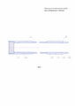
Фиг. 1. Труба насосно-компрессорная с размещенными на концах патрубками с наружной изоляцией и внутренним покрытиемFIG. 1. Pipe tubing with pipes located at the ends with external insulation and internal coating
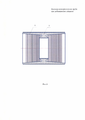
Фиг. 2. Разрез внутреннего герметизирующего узла между трубой и патрубком;FIG. 2. The cut of the internal sealing unit between the pipe and the pipe;
Фиг. 3. Профиль конической упорной резьбы;FIG. 3. Profile of tapered thrust thread;
Фиг. 4. Соединение насосно-компрессорных труб в колонну без муфты;FIG. 4. Connection of tubing to the column without coupling;
Фиг. 5. Соединение насосно-компрессорных труб в колонну с помощью муфты;FIG. 5. Connection of tubing to the string using a sleeve;
Фиг. 6. Муфта для соединения насосно-компрессорных труб в колонну.FIG. 6. Coupling for connecting tubing to the string.
Насосно-компрессорная труба (фиг. 1), содержит трубу 1 с калиброванными концами 2, 3 и с присоединенными к ним патрубками 4, 5. Калиброванные концы труб 2, 3 и сопряженные с ними внутренние поверхности патрубков 4, 5 выполнены с цилиндрической 6 и конической 7 поверхностями, при этом конические поверхности 7 выполнены ступенчатыми с образованием канавок, в которых размещен припой или клей-герметик, за счет которых производится образование неразъемного соединения концов трубы с патрубками.The tubing (Fig. 1) contains a
Патрубки 4, 5 изготавливаются из трубной заготовки длиной необходимой для нарезки резьбы, захвата ключом и осуществления посадки с натягом на длину не менее 1,5 наружного диаметра трубы из более прочного металла, чем материал трубы.The
Геометрия сопряженных поверхностей трубы и патрубков обеспечивает гарантированную посадку с натягом, образуя неразъемное, герметичное соединение.The geometry of the mating surfaces of the pipe and pipes provides a guaranteed fit with an interference fit, forming an integral, tight connection.
Внутренний диаметр патрубков 4, 5 и внутренний диаметр трубы 1 равны.The inner diameter of the
Соединение трубы 1 и патрубков 4, 5 выполнено с внутренним герметизирующим узлом 8 (фиг. 2), образуемым контактирующими между собой упорными конусными поверхностями 7, выполненными на патрубках.The connection of the
Патрубки 4, 5 выполнены с конической упорной резьбой 9, 10.The
Коническая упорная резьба 9, 10 у патрубков 4, 5 выполнена с конусностью 1:16, углом наклона опорной грани профиля витка от -2° до +4° к нормали осевой линии резьбы и углом наклона закладной грани профиля витка 10°-30° к нормали осевой линии резьбы.The
Коническая упорная резьба у патрубка 4 снабжена уплотнительным кольцом 11, выполненным из эластомерного материала с армированием.Conical thrust thread at the
Коническая упорная резьба 9, 10 (фиг. 3) выполнена с шагом (Р) в зависимости от диаметра трубы в диапазоне соотношения Р=d/50-100, при d≈50÷300 мм, профиль витков резьбы выполнен с угловыми соотношениями опорной и вспомогательной сторон как -2°/30°, номинальное соотношение размеров резьбы:The
- высота профиля резьбы на рабочем участке не более h≈0,57Р;- the height of the thread profile in the working area is not more than h≈0.57Р;
- ширина притупления вершины витков f≈0,29Р;- the width of the blunting of the top of the turns f≈0,29Р;
- средний диаметр резьбы на рабочем участке dcp≈d-0,57P;- the average diameter of the thread in the working area dcp≈d-0,57P;
- внутренний номинальный диаметр резьбы на рабочем участке d1≈d-1,13Р;- the internal nominal diameter of the thread on the working section d1≈d-1,13Р;
-ширина впадины резьбы fк≈0,22Р;- thread cavity width fк≈0.22Р;
- радиусы R1 и R2 сопряжения во впадине со сторонами профиля витка резьбы связаны соотношением R2≈2R1, где- the radii R1 and R2 of the conjugation in the depression with the sides of the thread thread profile are related by the relation R2≈2R1
- R1 - радиус сопряжения с опорной поверхностью профиля резьбы (-2°) и R1≈0,06Р,- R1 is the radius of pairing with the supporting surface of the thread profile (-2 °) and R1≈0.06Р,
- R2 - радиус сопряжения со вспомогательной поверхностью профиля резьбы (+30°),- R2 is the radius of the interface with the auxiliary surface of the thread profile (+ 30 °),
- r1 и r2 - радиусы притупления вершины витков резьбы, r1≈r2≈0,1Р.- r1 and r2 are the blunting radii of the apex of the thread turns, r1≈r2≈0.1Р.
Патрубки 4, 5 и труба 1 перед соединением подвергаются термообработке по отдельности.
Подготовку и калибровку концов трубы 1 на соосность и геометрию осуществляют прессом одновременно на обоих концах.The preparation and calibration of the ends of the
Соединение патрубков 4, 5 с трубой 1 может быть осуществлено на горизонтальном прессе с одновременным нагревом патрубков до температуры от 100° до 600°С.The connection of the
После контроля геометрических размеров, гидравлического испытания на внутреннюю и наружную поверхность патрубков 4, 5 и трубы 1 наносят защитное покрытие 12 (фиг. 1).After checking the geometric dimensions, hydraulic tests on the inner and outer surfaces of the
Уплотнительные сопряженные поверхности 7 имеют конусность, вызывающую расклинивающий эффект при приложении крутящего момента, который обеспечивает радиальную блокировку резьбы патрубков 4, 5, что в значительной мере повышает общую целостность их соединения.The sealing
Пример конкретного выполнения заявляемого технического решения.An example of a specific implementation of the proposed technical solution.
На трубной цилиндрической заготовке производят подготовку концов 2, 3 (фиг. 1). Осуществляют термическую обработку трубы и механическую обработку сопряженных поверхностей на концах. Подготовку и калибровку концов трубы на соосность и геометрию осуществляют прессом одновременно на обоих концах. Обработанные цилиндрические 6, конические 7 поверхности трубы 1 покрывают припоем или клеем-герметиком на длину контакта с соединительными патрубками. Патрубки 4, 5 изготавливают из прочной и износостойкой стали с термической обработкой и поверхностным упрочнением.On the cylindrical tube billet, ends 2, 3 are prepared (Fig. 1). Carry out the heat treatment of the pipe and the machining of the mating surfaces at the ends. The preparation and calibration of the pipe ends for alignment and geometry is carried out by a press at both ends simultaneously. The treated cylindrical 6, conical 7 surfaces of the
Внутренние поверхности патрубков механически обрабатывают под посадочные цилиндрические 6 и конические 7 поверхности, контактирующие с трубой, нарезают коническую упорную резьбу и проводят упрочнение всех поверхностей патрубков карбонитрированием.The inner surfaces of the nozzles are machined to fit the cylindrical 6 and conical 7 surfaces in contact with the pipe, a tapered threaded thread is cut, and all surfaces of the nozzles are hardened by carbonitriding.
Соединение патрубков с трубой осуществляют на горизонтальном прессе с одновременным нагревом патрубков до температуры 100°-600°С. После контроля геометрических размеров, гидравлического испытания на внутреннюю поверхность патрубков и трубы наносят защитные покрытия 12.The connection of the nozzles with the pipe is carried out on a horizontal press while heating the nozzles to a temperature of 100 ° -600 ° C. After checking the geometric dimensions, hydraulic tests,
Патрубки изготавливают для двух видов соединений насосно-компрессорных труб в колонну:Pipes are made for two types of tubing connections in a string:
- для соединения насосно-компрессорных труб в колонну без муфты;- for connecting tubing into a string without a sleeve;
- для соединения насосно-компрессорных труб в колонну с помощью муфты.- to connect the tubing to the string using a sleeve.
Соединение насосно-компрессорных труб в колонну без муфты (фиг. 4) представляет собой соединение концов труб, соединенных с ниппельным патрубком 4 и муфтовым патрубком 5. Резьбы 9, 10 на патрубках служат для соединения труб в колонну.The connection of tubing to the string without a sleeve (Fig. 4) is the connection of the ends of the pipes connected to the
Соединение насосно-компрессорных труб в колонну с помощью муфты (фиг. 5) представляет собой соединение концов труб, соединенных с ниппельным патрубком 4 и муфты 13. Резьбы на патрубках служат для соединения с внутренней конической упорной резьбой 14 муфты 13 (фиг. 6) для соединения труб в колонну.The connection of tubing to the string using the sleeve (Fig. 5) is a connection of the ends of the pipes connected to the
Соединения насосно-компрессорных труб могут быть осуществлены на стандартном оборудовании с использование современных материалов и технологий.The tubing connections can be made using standard equipment using modern materials and technologies.
Таким образом, заявленная насосно-компрессорная труба позволяет повысить эксплуатационные качества колонны насосно-компрессорных труб, а именно обеспечивает высокую герметичность при действии на них значительных разнонаправленных нагрузок (растяжение, сжатие, изгиб), износостойкость соединения, снижение гидравлических потерь за счет отсутствия мест сужения в трубной колонне и прохождения жидкости по трубам с покрытием, улучшение характеристик свинчиваемости за счет получения равнопрочного соединения труб с патрубками, обладающего высокой усталостной прочностью.Thus, the claimed tubing allows to improve the performance of the tubing string, namely it provides high tightness when exposed to significant multidirectional loads (tension, compression, bending), wear resistance of the connection, reduced hydraulic losses due to the absence of narrowing points in the pipe string and the passage of fluid through the coated pipes, improving the make-up characteristics by obtaining an equal strength pipe connection with nozzles having high fatigue strength.
Основные достигнутые показатели показаны в таблице:The main indicators achieved are shown in the table:

Были проведены промысловые испытания предлагаемой насосно-компрессорной трубы на одной из нефтяных скважин ПАО «Татнефть», которые показали надежность конструкции, возможность работы с различными материалами, высокую герметичность, улучшенные характеристики свинчивания. Намечено внедрение его в производство на 4 квартал 2017 г.Field tests of the proposed tubing were carried out at one of the oil wells of PJSC TATNEFT, which showed the reliability of the design, the ability to work with various materials, high tightness, and improved make-up characteristics. Its introduction into production is planned for the 4th quarter of 2017.
Claims (18)
Priority Applications (1)
| Application Number | Priority Date | Filing Date | Title |
|---|---|---|---|
| RU2016119189A RU2665663C2 (en) | 2016-10-19 | 2016-10-19 | Production well tubing |
Applications Claiming Priority (1)
| Application Number | Priority Date | Filing Date | Title |
|---|---|---|---|
| RU2016119189A RU2665663C2 (en) | 2016-10-19 | 2016-10-19 | Production well tubing |
Publications (2)
| Publication Number | Publication Date |
|---|---|
| RU2016119189A RU2016119189A (en) | 2018-04-20 |
| RU2665663C2 true RU2665663C2 (en) | 2018-09-03 |
Family
ID=61974556
Family Applications (1)
| Application Number | Title | Priority Date | Filing Date |
|---|---|---|---|
| RU2016119189A RU2665663C2 (en) | 2016-10-19 | 2016-10-19 | Production well tubing |
Country Status (1)
| Country | Link |
|---|---|
| RU (1) | RU2665663C2 (en) |
Cited By (1)
| Publication number | Priority date | Publication date | Assignee | Title |
|---|---|---|---|---|
| RU197702U1 (en) * | 2020-02-06 | 2020-05-22 | Юрий Владимирович Генов | Modified coupling |
Citations (5)
| Publication number | Priority date | Publication date | Assignee | Title |
|---|---|---|---|---|
| WO2002065012A1 (en) * | 2001-02-09 | 2002-08-22 | Vallourec Mannesmann Oil & Gas France | Tubular threaded joint with trapezoid threads having convex bulged thread surface |
| RU2256767C1 (en) * | 2004-05-06 | 2005-07-20 | Закрытое акционерное общество "Инвест ПромТорг" | Threaded oil-field pipe joint with increased air-tightness (variants) and production method thereof (variants) |
| WO2010066365A1 (en) * | 2008-12-10 | 2010-06-17 | Vallourec Mannesmann Oil & Gas France | Sealed tubular connection used in the oil industry, and method for producing said connection |
| EA017155B1 (en) * | 2007-11-08 | 2012-10-30 | Сумитомо Метал Индастриз, Лтд. | Threaded joint for steel pipes |
| RU2561253C2 (en) * | 2010-06-17 | 2015-08-27 | Валлурек Маннесманн Ойл Энд Гес Франс | Threaded joint and method for its production |
-
2016
- 2016-10-19 RU RU2016119189A patent/RU2665663C2/en active
Patent Citations (5)
| Publication number | Priority date | Publication date | Assignee | Title |
|---|---|---|---|---|
| WO2002065012A1 (en) * | 2001-02-09 | 2002-08-22 | Vallourec Mannesmann Oil & Gas France | Tubular threaded joint with trapezoid threads having convex bulged thread surface |
| RU2256767C1 (en) * | 2004-05-06 | 2005-07-20 | Закрытое акционерное общество "Инвест ПромТорг" | Threaded oil-field pipe joint with increased air-tightness (variants) and production method thereof (variants) |
| EA017155B1 (en) * | 2007-11-08 | 2012-10-30 | Сумитомо Метал Индастриз, Лтд. | Threaded joint for steel pipes |
| WO2010066365A1 (en) * | 2008-12-10 | 2010-06-17 | Vallourec Mannesmann Oil & Gas France | Sealed tubular connection used in the oil industry, and method for producing said connection |
| RU2561253C2 (en) * | 2010-06-17 | 2015-08-27 | Валлурек Маннесманн Ойл Энд Гес Франс | Threaded joint and method for its production |
Cited By (1)
| Publication number | Priority date | Publication date | Assignee | Title |
|---|---|---|---|---|
| RU197702U1 (en) * | 2020-02-06 | 2020-05-22 | Юрий Владимирович Генов | Modified coupling |
Also Published As
| Publication number | Publication date |
|---|---|
| RU2016119189A (en) | 2018-04-20 |
Similar Documents
| Publication | Publication Date | Title |
|---|---|---|
| RU2516775C2 (en) | Pipe component for drilling and operation of hydrocarbon wells and resulting threaded joint | |
| EP1540227B1 (en) | Threaded tube joint | |
| US6755447B2 (en) | Production riser connector | |
| EP0703396B1 (en) | Threaded joint for oil well pipes | |
| US7997627B2 (en) | Threaded joint for steel pipes | |
| US4537429A (en) | Tubular connection with cylindrical and tapered stepped threads | |
| EP1332308B8 (en) | Open type wedgethread connection | |
| EP1101056B1 (en) | Threaded and coupled connection for improved fatigue resistance | |
| EP3064818B1 (en) | Threaded joint for heavy-walled oil country tubular goods | |
| US8181998B2 (en) | Threaded pipe connection | |
| US20020017788A1 (en) | Pipe connector | |
| RU2604461C1 (en) | Threaded pipe connection | |
| EA021308B1 (en) | Threaded joint for steel pipes | |
| US4500224A (en) | Coupling for sucker rod assembly | |
| CZ2003184A3 (en) | Pipe threaded joint with reinforced side support | |
| US20110215569A1 (en) | Connection between a drill pipe and a connector | |
| GB2388169A (en) | Pipe joint | |
| US10274112B2 (en) | Threaded connection | |
| RU2665663C2 (en) | Production well tubing | |
| US9644771B1 (en) | Threaded coupling | |
| US10273765B2 (en) | Threaded connection | |
| RU2324857C1 (en) | Threaded connection of oil well tubing (variants) | |
| US5143411A (en) | Threaded tubular connection | |
| US5018771A (en) | Threaded tubular connection | |
| RU2808401C1 (en) | Threaded connection of pump-compressor pipes |