RU2644839C2 - Disc brake mechanism with air clearance control device and air clearance control method - Google Patents
Disc brake mechanism with air clearance control device and air clearance control method Download PDFInfo
- Publication number
- RU2644839C2 RU2644839C2 RU2015135530A RU2015135530A RU2644839C2 RU 2644839 C2 RU2644839 C2 RU 2644839C2 RU 2015135530 A RU2015135530 A RU 2015135530A RU 2015135530 A RU2015135530 A RU 2015135530A RU 2644839 C2 RU2644839 C2 RU 2644839C2
- Authority
- RU
- Russia
- Prior art keywords
- brake
- values
- air gap
- control device
- actual
- Prior art date
Links
Images
Classifications
-
- F—MECHANICAL ENGINEERING; LIGHTING; HEATING; WEAPONS; BLASTING
- F16—ENGINEERING ELEMENTS AND UNITS; GENERAL MEASURES FOR PRODUCING AND MAINTAINING EFFECTIVE FUNCTIONING OF MACHINES OR INSTALLATIONS; THERMAL INSULATION IN GENERAL
- F16D—COUPLINGS FOR TRANSMITTING ROTATION; CLUTCHES; BRAKES
- F16D55/00—Brakes with substantially-radial braking surfaces pressed together in axial direction, e.g. disc brakes
- F16D55/02—Brakes with substantially-radial braking surfaces pressed together in axial direction, e.g. disc brakes with axially-movable discs or pads pressed against axially-located rotating members
- F16D55/22—Brakes with substantially-radial braking surfaces pressed together in axial direction, e.g. disc brakes with axially-movable discs or pads pressed against axially-located rotating members by clamping an axially-located rotating disc between movable braking members, e.g. movable brake discs or brake pads
- F16D55/224—Brakes with substantially-radial braking surfaces pressed together in axial direction, e.g. disc brakes with axially-movable discs or pads pressed against axially-located rotating members by clamping an axially-located rotating disc between movable braking members, e.g. movable brake discs or brake pads with a common actuating member for the braking members
- F16D55/225—Brakes with substantially-radial braking surfaces pressed together in axial direction, e.g. disc brakes with axially-movable discs or pads pressed against axially-located rotating members by clamping an axially-located rotating disc between movable braking members, e.g. movable brake discs or brake pads with a common actuating member for the braking members the braking members being brake pads
- F16D55/2255—Brakes with substantially-radial braking surfaces pressed together in axial direction, e.g. disc brakes with axially-movable discs or pads pressed against axially-located rotating members by clamping an axially-located rotating disc between movable braking members, e.g. movable brake discs or brake pads with a common actuating member for the braking members the braking members being brake pads in which the common actuating member is pivoted
-
- F—MECHANICAL ENGINEERING; LIGHTING; HEATING; WEAPONS; BLASTING
- F16—ENGINEERING ELEMENTS AND UNITS; GENERAL MEASURES FOR PRODUCING AND MAINTAINING EFFECTIVE FUNCTIONING OF MACHINES OR INSTALLATIONS; THERMAL INSULATION IN GENERAL
- F16D—COUPLINGS FOR TRANSMITTING ROTATION; CLUTCHES; BRAKES
- F16D55/00—Brakes with substantially-radial braking surfaces pressed together in axial direction, e.g. disc brakes
- F16D55/02—Brakes with substantially-radial braking surfaces pressed together in axial direction, e.g. disc brakes with axially-movable discs or pads pressed against axially-located rotating members
- F16D55/22—Brakes with substantially-radial braking surfaces pressed together in axial direction, e.g. disc brakes with axially-movable discs or pads pressed against axially-located rotating members by clamping an axially-located rotating disc between movable braking members, e.g. movable brake discs or brake pads
- F16D55/224—Brakes with substantially-radial braking surfaces pressed together in axial direction, e.g. disc brakes with axially-movable discs or pads pressed against axially-located rotating members by clamping an axially-located rotating disc between movable braking members, e.g. movable brake discs or brake pads with a common actuating member for the braking members
- F16D55/225—Brakes with substantially-radial braking surfaces pressed together in axial direction, e.g. disc brakes with axially-movable discs or pads pressed against axially-located rotating members by clamping an axially-located rotating disc between movable braking members, e.g. movable brake discs or brake pads with a common actuating member for the braking members the braking members being brake pads
-
- F—MECHANICAL ENGINEERING; LIGHTING; HEATING; WEAPONS; BLASTING
- F16—ENGINEERING ELEMENTS AND UNITS; GENERAL MEASURES FOR PRODUCING AND MAINTAINING EFFECTIVE FUNCTIONING OF MACHINES OR INSTALLATIONS; THERMAL INSULATION IN GENERAL
- F16D—COUPLINGS FOR TRANSMITTING ROTATION; CLUTCHES; BRAKES
- F16D65/00—Parts or details
- F16D65/38—Slack adjusters
- F16D65/40—Slack adjusters mechanical
- F16D65/52—Slack adjusters mechanical self-acting in one direction for adjusting excessive play
- F16D65/56—Slack adjusters mechanical self-acting in one direction for adjusting excessive play with screw-thread and nut
- F16D65/567—Slack adjusters mechanical self-acting in one direction for adjusting excessive play with screw-thread and nut for mounting on a disc brake
- F16D65/568—Slack adjusters mechanical self-acting in one direction for adjusting excessive play with screw-thread and nut for mounting on a disc brake for synchronous adjustment of actuators arranged in parallel
-
- F—MECHANICAL ENGINEERING; LIGHTING; HEATING; WEAPONS; BLASTING
- F16—ENGINEERING ELEMENTS AND UNITS; GENERAL MEASURES FOR PRODUCING AND MAINTAINING EFFECTIVE FUNCTIONING OF MACHINES OR INSTALLATIONS; THERMAL INSULATION IN GENERAL
- F16D—COUPLINGS FOR TRANSMITTING ROTATION; CLUTCHES; BRAKES
- F16D66/00—Arrangements for monitoring working conditions, e.g. wear, temperature
- F16D66/02—Apparatus for indicating wear
- F16D66/021—Apparatus for indicating wear using electrical detection or indication means
- F16D66/026—Apparatus for indicating wear using electrical detection or indication means indicating different degrees of lining wear
- F16D66/027—Sensors therefor
-
- G—PHYSICS
- G01—MEASURING; TESTING
- G01N—INVESTIGATING OR ANALYSING MATERIALS BY DETERMINING THEIR CHEMICAL OR PHYSICAL PROPERTIES
- G01N3/00—Investigating strength properties of solid materials by application of mechanical stress
- G01N3/56—Investigating resistance to wear or abrasion
-
- F—MECHANICAL ENGINEERING; LIGHTING; HEATING; WEAPONS; BLASTING
- F16—ENGINEERING ELEMENTS AND UNITS; GENERAL MEASURES FOR PRODUCING AND MAINTAINING EFFECTIVE FUNCTIONING OF MACHINES OR INSTALLATIONS; THERMAL INSULATION IN GENERAL
- F16D—COUPLINGS FOR TRANSMITTING ROTATION; CLUTCHES; BRAKES
- F16D66/00—Arrangements for monitoring working conditions, e.g. wear, temperature
- F16D2066/001—Temperature
-
- F—MECHANICAL ENGINEERING; LIGHTING; HEATING; WEAPONS; BLASTING
- F16—ENGINEERING ELEMENTS AND UNITS; GENERAL MEASURES FOR PRODUCING AND MAINTAINING EFFECTIVE FUNCTIONING OF MACHINES OR INSTALLATIONS; THERMAL INSULATION IN GENERAL
- F16D—COUPLINGS FOR TRANSMITTING ROTATION; CLUTCHES; BRAKES
- F16D66/00—Arrangements for monitoring working conditions, e.g. wear, temperature
- F16D2066/003—Position, angle or speed
-
- F—MECHANICAL ENGINEERING; LIGHTING; HEATING; WEAPONS; BLASTING
- F16—ENGINEERING ELEMENTS AND UNITS; GENERAL MEASURES FOR PRODUCING AND MAINTAINING EFFECTIVE FUNCTIONING OF MACHINES OR INSTALLATIONS; THERMAL INSULATION IN GENERAL
- F16D—COUPLINGS FOR TRANSMITTING ROTATION; CLUTCHES; BRAKES
- F16D66/00—Arrangements for monitoring working conditions, e.g. wear, temperature
- F16D2066/006—Arrangements for monitoring working conditions, e.g. wear, temperature without direct measurement of the quantity monitored, e.g. wear or temperature calculated form force and duration of braking
Abstract
Description
Изобретение относится к дисковому тормозному механизму, в частности, для безрельсового транспортного средства, с устройством контроля воздушного зазора в соответствии с ограничительной частью пункта 1 формулы изобретения. Изобретение относится также к способу контроля воздушного зазора дискового тормозного механизма.The invention relates to a disc braking mechanism, in particular for a trackless vehicle, with an air gap control device in accordance with the restrictive part of
Такого рода дисковые тормозные механизмы известны в различных вариантах осуществления. Для их безопасной и надежной работы необходимо, чтобы между парами трения (тормозными накладками и тормозным диском) и в любых рабочих условиях сохранялся заданный зазор, который обозначается как воздушный зазор.Such disc brakes are known in various embodiments. For their safe and reliable operation, it is necessary that between the friction pairs (brake linings and brake disc) and in any operating conditions, a predetermined clearance is maintained, which is designated as an air gap.
Известны устройства регулировки износа в различных вариантах осуществления, такие, к примеру, как механические регулировочные устройства, которые у обычных сегодня для тяжелых грузовых транспортных средств пневматически работающих дисковых тормозных механизмов обеспечивают постоянный в определенных границах воздушный зазор. При этом при каждом приведении в действие тормозной системы активируется регулировочное устройство, к примеру, посредством подающего элемента зажимного устройства дискового тормозного механизма. При износе тормозных накладок и тормозного диска осуществляется автоматическая регулировка накладок посредством регулировочного устройства, к примеру, посредством перемещения изменяемых по длине нажимных стержней.Known devices for adjusting wear in various embodiments, such as, for example, mechanical adjusting devices, which are common in today's heavy freight vehicles with pneumatically operated disc brakes provide a constant air gap within certain limits. In this case, at each actuation of the brake system, an adjustment device is activated, for example, by means of a feeding element of the clamping device of the disk brake mechanism. When the brake linings and brake disc are worn, the linings are automatically adjusted by means of an adjusting device, for example, by moving the pressure rods that are variable in length.
Конструктивно заданный воздушный зазор имеет фиксированные геометрические параметры в участвующих в процессе регулировки конструктивных элементах. Непрерывный контроль воздушного зазора невозможен, ввиду чисто механических условий или из-за отсутствия датчиков. Поэтому, в настоящее время, предусмотрено только проводимое в рамках регулярной проверки тормозной системы, измерение воздушного зазора вручную. Правда, эта проверка производится, естественно, лишь с большими временными интервалами или интервалами пробега машины, к примеру, при замене накладок и, кроме того, лишь в охлажденном состоянии тормозного механизма. Таким образом, воздушный зазор на длительных участках пути и во время различных рабочих состояний дискового тормозного механизма остается без наблюдения, и возможные критические изменения остаются не выявленными.The structurally specified air gap has fixed geometric parameters in the structural elements involved in the adjustment process. Continuous monitoring of the air gap is not possible due to purely mechanical conditions or due to the lack of sensors. Therefore, at present, only manual measurement of the air gap is carried out as part of the regular check of the brake system. True, this check is carried out, of course, only with large time intervals or vehicle run intervals, for example, when replacing pads and, in addition, only in the cooled state of the brake mechanism. Thus, the air gap over long sections of the track and during various operating conditions of the disk brake mechanism is left unattended, and possible critical changes remain undetected.
Известны конструкции дисковых тормозных механизмов, которые позволяют производить контроль воздушного зазора и, кроме того, даже его активную регулировку или корректировку во время работы. К примеру, этого можно добиться у приводимого в действие пневматическим способом дискового тормозного механизма посредством электрического приведения в действие регулировочного устройства и, тем самым, перемещения тормозных накладок относительно тормозного диска. Соответствующая логическая система управления использует рабочие параметры электрического привода, чтобы измерить имеющийся воздушный зазор и, при необходимости, отрегулировать желаемый воздушный зазор. DE 19731696 А1 иллюстрирует такой пример.Known designs of disc brakes, which allow for control of the air gap and, in addition, even its active adjustment or adjustment during operation. For example, this can be achieved with a pneumatically actuated disc brake by electrically actuating the adjusting device and thereby moving the brake pads relative to the brake disc. An appropriate logic control system uses the operating parameters of the electric drive to measure the existing air gap and, if necessary, adjust the desired air gap. DE 19731696 A1 illustrates such an example.
Однако такого рода конструкции не могут войти на рынок, будучи обусловлены высоким технологическим скачком в развитии, а также сопутствующим расходами.However, such constructions cannot enter the market, being caused by a high technological leap in development, as well as associated costs.
Следующий вариант конструкции тормозного механизма, который может обеспечить контроль воздушного зазора, известен в форме электромеханического дискового тормозного механизма. Приведение в действие механики тормозного механизма производится при этом чисто электрически, и посредством необходимой для торможения электронной системы управления может быть обеспечен контроль и регулировка воздушного зазора. Эта конструкция представляет собой, однако, еще больший технологический шаг вперед, и серийное использование таких систем в грузовых транспортных средствах не поддается прогнозу. Такой пример иллюстрирует документ DE 19933962 С2.A further design variant of the brake mechanism that can provide air gap control is known in the form of an electromechanical disc brake. The actuation of the mechanics of the brake mechanism is carried out in this case purely electrically, and through the electronic control system necessary for braking, control and adjustment of the air gap can be provided. This design, however, represents an even greater technological step forward, and the serial use of such systems in freight vehicles is not predictable. Such an example is illustrated in document DE 19933962 C2.
Поэтому, задача настоящего изобретения состоит в том, чтобы улучшить дисковый тормозной механизм, в частности, пневматический дисковый тормозной механизм традиционной конструкции, с максимально небольшими конструктивными и стоимостными издержками, посредством системы контроля воздушного зазора.Therefore, an object of the present invention is to improve a disk brake mechanism, in particular a pneumatic disk brake mechanism of a conventional design, with the smallest possible structural and cost costs, by means of an air gap control system.
Следующая задача состоит в создании усовершенствованного способа контроля воздушного зазора.The next task is to create an improved way to control the air gap.
Задача решается посредством дискового тормозного механизма, охарактеризованного признаками пункта 1 формулы изобретения, а также посредством способа, охарактеризованного признаками пункта 12 формулы изобретения.The problem is solved by means of a disk braking mechanism characterized by the characteristics of
Основная идея изобретения состоит в том, что предусмотрено устройство контроля воздушного зазора с устройством управления, которое соединено с датчиком износа и с устройством управления тормозным механизмом. Для этого используется уже имеющийся датчик износа, который обычно применяется в дисковых тормозных механизмах.The main idea of the invention is that an air gap control device is provided with a control device that is connected to a wear sensor and to a brake control device. For this, an existing wear sensor is used, which is usually used in disc brakes.
Дисковый тормозной механизм в соответствии с изобретением, в частности, для безрельсового транспортного средства, включает в себя зажимное устройство, в частности, с тормозным рычагом, регулировочное устройство, которое соединено с зажимным устройством, в частности, с тормозным рычагом, для регулировки износа тормозных накладок и тормозного диска, датчик износа для регистрации значения износа тормозных накладок и тормозного диска и устройство управления тормозным механизмом. Дисковый тормозной механизм имеет устройство контроля воздушного зазора с устройством управления, которое соединено с датчиком износа и с устройством управления тормозным механизмом.The disk brake mechanism in accordance with the invention, in particular for a trackless vehicle, includes a clamping device, in particular with a brake lever, an adjustment device that is connected to a clamping device, in particular with a brake lever, for adjusting brake lining wear and a brake disk, a wear sensor for recording a wear value of the brake linings and the brake disk, and a brake control device. The disk brake mechanism has an air gap control device with a control device that is connected to a wear sensor and to a brake control device.
На основании этого выявляется преимущество в том, что с небольшими издержками создается дисковый тормозной механизм с устройством контроля воздушного зазора.On the basis of this, an advantage is revealed that, at low costs, a disk brake mechanism is created with an air gap control device.
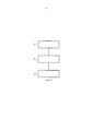
Способ в соответствии с изобретением для контроля воздушного зазора такого дискового тормозного механизма включает в себя этапы способа: (S1) образование фактических пар значений из фактических значений давления в тормозной системе и зарегистрированных фактических значений сигнала датчика износа во время процесса торможения; (S2) сравнение образованных фактических пар значений с ранее сохраненными контрольными значениями; и (S3) оценка результатов сравнения и выдача уведомлений для контроля воздушного зазора.The method in accordance with the invention for controlling the air gap of such a disk brake mechanism includes the method steps: (S1) generating actual pairs of values from the actual pressure values in the brake system and the recorded actual values of the wear sensor signal during the braking process; (S2) comparing the generated actual value pairs with previously stored reference values; and (S3) evaluating the comparison results and issuing notifications to control the air gap.
Таким образом, в предпочтительном варианте возможно распознавать недопустимые отклонения от определенных или заранее заданных значений воздушного зазора и извещать или сообщать об этом.Thus, in a preferred embodiment, it is possible to recognize unacceptable deviations from certain or predetermined values of the air gap and to notify or report this.
Другие предпочтительные варианты осуществления представлены в последующих зависимых пунктах формулы изобретения.Other preferred embodiments are presented in the following dependent claims.
В варианте осуществления устройство управления устройства контроля воздушного зазора осуществлено для регистрации фактического значения сигнала датчика износа посредством блока распознавания. Блок распознавания может распознавать изменение во времени фактического значения сигнала датчика износа. Это является особенно предпочтительным тогда, когда датчик износа перемещается. Таким образом, сразу может быть зарегистрировано изменение.In an embodiment, the control device of the air gap control device is arranged to record the actual value of the wear sensor signal by the recognition unit. The recognition unit can recognize a change in time of the actual value of the wear sensor signal. This is especially preferred when the wear sensor is moving. Thus, a change can be immediately recorded.
Другой вариант осуществления предусматривает, что устройство управления устройства контроля воздушного зазора для образования фактических пар значений из фактических значений давления в тормозной системе и зарегистрированных фактических значений сигнала датчика износа, а также для сравнения фактических пар значений с записанными в память контрольными значениями, снабжено блоком сравнения. Контрольными значениями могут быть, к примеру, характеристические кривые «давление/ход» тормозного цилиндра соответствующего дискового тормозного механизма. Особо предпочтительным является, если эти характеристические кривые «давление/ход» при новом состоянии будут запрограммированы, что делает возможным другой вариант осуществления.Another embodiment provides that the control device of the air gap control device for generating actual pairs of values from the actual pressure values in the brake system and the recorded actual values of the wear sensor signal, as well as for comparing the actual pairs of values with the stored control values, is equipped with a comparison unit. Reference values can be, for example, the characteristic pressure / stroke curves of the brake cylinder of the corresponding disc brake. It is particularly preferred if these pressure / stroke characteristic curves are programmed under a new state, which makes another embodiment possible.
Так фактические значения тормозного давления могут заимствоваться из устройства управления тормозным механизмом или/и являются выходными значениями, по меньшей мере, одного другого датчика. Устройство управления тормозным механизмом может иметь соответствующие табличные значения и/или значения характеристических кривых. Естественно, может использоваться и имеющийся датчик давления или же датчик усилия. Сохраненные контрольные значения также записаны в память устройства управления тормозным механизмом.So the actual brake pressure values can be borrowed from the brake control device and / or are the output values of at least one other sensor. The brake control device may have corresponding tabular values and / or characteristic curve values. Naturally, either the existing pressure sensor or the force sensor can be used. The stored control values are also recorded in the memory of the brake control device.
Кроме того, сохраненные контрольные значения могут быть записаны в память запоминающего блока устройства управления. При этом предпочтительным является, если это запрограммированные значения характеристических кривых и другие запрограммированные значения, так как в этом случае обеспечивается более высокая точность.In addition, the stored control values can be recorded in the memory of the storage unit of the control device. Moreover, it is preferable if these are the programmed values of the characteristic curves and other programmed values, since in this case higher accuracy is ensured.
В следующем варианте осуществления устройство управления устройства контроля воздушного зазора имеет блок оценки результатов для оценки данных блока сравнения. Таким образом, может производиться дифференцирование зарегистрированных значений на основании тенденций и дополнительных условий. В соответствии с этим, сигналы предупреждения и уведомления могут выдаваться точно.In a further embodiment, the control device of the air gap control device has a result evaluation unit for evaluating the data of the comparison unit. Thus, differentiation of recorded values can be made based on trends and additional conditions. Accordingly, warnings and notifications can be generated accurately.
Далее предусмотрено, что устройство контроля воздушного зазора включает в себя далее сигнальный блок, который на основании оценки блока оценки результатов выдает уведомления по уровню контроля воздушного зазора акустическим, визуальным, осязательным или/и буквенно-цифровым способом. Таким образом, водитель транспортного средства достаточно заблаговременно может быть поставлен в известность о наличии проблемы или о соблюдении сроков технического обслуживания и, соответственно, о поиске ремонтной мастерской. Кроме того, уведомления могут быть записаны в память и могут быть запрошены обслуживающим персоналом.It is further provided that the air gap control device further includes a signal unit, which, based on the evaluation of the result evaluation unit, provides notifications of the air gap control level in an acoustic, visual, tactile and / or alphanumeric way. Thus, the driver of the vehicle can be informed in sufficient time in advance about the presence of a problem or about the observance of the terms of maintenance and, accordingly, about the search for a repair shop. In addition, notifications can be recorded in memory and may be requested by service personnel.
Для привлечения дополнительных условий и для оценки тенденции и зарегистрированных значений устройство контроля воздушного зазора может иметь далее, по меньшей мере, одно устройство регистрации температуры. При этом могут использоваться имеющиеся или же дополнительные датчики температуры.To attract additional conditions and to assess trends and recorded values, the air gap control device may further have at least one temperature recording device. In this case, existing or additional temperature sensors can be used.
Устройство управления устройства контроля воздушного зазора может являться составной частью устройства управления тормозным механизмом, вследствие чего нет необходимости в наличии значительной дополнительной занимаемой площади в дисковом тормозном механизме.The control device of the air gap control device may be an integral part of the brake control device, as a result of which there is no need for a significant additional footprint in the disk brake mechanism.
На этапе (S1) способа «образование фактических пар (p/U) значений» фактические значения давления в тормозной системе выдаются устройством управления тормозным механизмом или/и дополнительным датчиком. Значения давления в тормозной системе уже имеются в устройстве управления тормозным механизмом, так что нет необходимости в дополнительных датчиках с использованием дополнительной занимаемой площади.In step (S1) of the method “generation of actual pairs (p / U) values”, the actual pressure values in the brake system are issued by the brake control device and / or an additional sensor. Pressure values in the brake system are already available in the brake control device, so there is no need for additional sensors using the additional footprint.
В варианте осуществления предусмотрено, что на этапе (S3) способа «оценка» заранее устанавливаемый, номинальный воздушный зазор определяется без регулировки, когда фактическая пара значений соответствует записанной в памяти паре значений, которая назначена корректному воздушному зазору, и следующая пара значений не отличается изменением зарегистрированного фактического значения сигнала датчика износа, однако, отличается сильным подъемом давления в тормозной системе. Таким образом, возможно простое отличие данного случая от других случаев.In an embodiment, it is provided that, in step (S3) of the “estimation” method, a predetermined, nominal air gap is determined without adjustment when the actual pair of values corresponds to a pair of values stored in the memory that is assigned to the correct air gap, and the next pair of values does not differ in the registered The actual value of the wear signal, however, is characterized by a strong increase in pressure in the brake system. Thus, a simple difference between this case and other cases is possible.
При этом на этапе (S3) способа «оценка» заранее устанавливаемый, номинальный и, ввиду износа, увеличенный воздушный зазор устанавливается с регулировкой, когда фактическая пара значений соответствует записанной в памяти паре значений, которая назначена корректному воздушному зазору, и следующая пара значений отличается изменением зарегистрированного фактического значения сигнала датчика износа, однако, не отличается сильным подъемом давления в тормозной системе.Moreover, in step (S3) of the “evaluation” method, a predetermined, nominal and, due to wear, increased air gap is set with adjustment when the actual pair of values corresponds to the stored in the pair of values that are assigned to the correct air gap, and the next pair of values differs by a change the recorded actual value of the wear sensor signal, however, is not marked by a strong increase in pressure in the brake system.
А для следующего случая на этапе (S3) способа «оценка» заранее устанавливаемый, номинальный воздушный зазор определяется в качестве выходящего за границы нижнего предельного значения, когда давление в тормозной системе фактической пары значений меньше давления в тормозной системе, которое назначено заранее устанавливаемому, корректному воздушному зазору, и следующая пара значений не отличается изменением зарегистрированного фактического значения сигнала датчика износа, однако, отличается сильным подъемом давления в тормозной системе, или отличается изменением зарегистрированного фактического значения сигнала датчика износа, однако, не отличается сильным подъемом давления в тормозной системе.And for the next case, in step (S3) of the “estimation” method, a pre-set, nominal air gap is determined as the lower limit value that goes beyond the boundaries, when the pressure in the brake system of the actual pair of values is less than the pressure in the brake system that is assigned to a pre-set, correct air the gap, and the next pair of values does not differ by changing the registered actual value of the wear sensor signal, however, it is characterized by a strong pressure increase in the brake systems e, or is characterized by a change in the recorded actual value of the wear sensor signal, however, it does not differ by a strong increase in pressure in the brake system.
Таким образом, в предпочтительном варианте может быть произведено распознавание случаев на основании пар значений, с целью контроля воздушного зазора.Thus, in a preferred embodiment, case recognition can be made based on pairs of values in order to control the air gap.
Далее на этапе (S3) способа «оценка» за счет использования устройства регистрации температуры могут быть учтены термические воздействия, что повышает надежность уведомлений.Next, in step (S3) of the “estimation” method, by using the temperature recording device, thermal effects can be taken into account, which increases the reliability of notifications.
Дальнейшее повышение надежности достигается посредством того, что на этапе (S3) способа «оценка» выдача предупреждения или предупредительного сигнала производится только после определенного количества торможений.A further increase in reliability is achieved by the fact that at step (S3) of the “evaluation” method, a warning or warning is issued only after a certain amount of braking.
Посредством заранее произведенного программирования контрольных значений в устройство управления тормозным механизмом или/и в запоминающее устройство также возможно повышение надежности.By pre-programming the control values to the brake control device and / or to the memory, it is also possible to increase reliability.
К тому же, в следующем варианте осуществления в предпочтительном варианте возможно определение точки трения посредством того, что фактические пары значений сравниваются с записанными в памяти парами значений, когда одна фактическая пара значений из фактических пар значений, которые сравниваются с записанными в память парами значений, отличается сильным подъемом давления в тормозной системе.In addition, in the following embodiment, in a preferred embodiment, it is possible to determine the friction point by means that the actual value pairs are compared with the stored value pairs, when one actual value pair of the actual value pairs that are compared with the value pairs stored in the memory is different a strong increase in pressure in the brake system.
Посредством устройства контроля воздушного зазора в соответствии с изобретением и соответствующего способа в соответствии с изобретением для контроля воздушного зазора фактический воздушный зазор может непрерывно или достаточно часто подвергаться регистрации и контролю.By means of the air gap control device in accordance with the invention and the corresponding method in accordance with the invention for monitoring the air gap, the actual air gap can be continuously or often enough registered and monitored.
Возможно дифференцированное распознавание увеличенного, корректного и вышедшего за нижнюю границу воздушного зазора.Differential recognition of increased, correct and out of the lower limit of the air gap is possible.
Воздушный зазор может быть специальным образом проконтролирован и зарегистрирован для каждого тормозного механизма.The air gap can be specially controlled and registered for each brake mechanism.
Затраты при этом минимизированы посредством того, что нет необходимости в дополнительной занимаемой площади, и посредством того, что могут быть использованы выходные данные уже имеющихся функциональных блоков.The costs are minimized by the fact that there is no need for additional occupied space, and by the fact that the output of existing functional blocks can be used.
В дополнительных датчиках на колесном тормозе для регистрации воздушного зазора или воздушной щели нет необходимости. Соответствующие отдельные электронные блоки оценки результатов (сравнение заданных и фактических значений) и блоки вывода могут отсутствовать.There is no need for additional sensors on the wheel brake to detect air gap or air gap. Corresponding separate electronic units for evaluating the results (comparison of set and actual values) and output units may be absent.
Изобретение поясняется чертежами, на которых представлено следующее:The invention is illustrated by drawings, which represent the following:
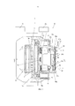
фиг. 1 - схематичный вид в частичном разрезе примера осуществления дискового тормозного механизма в соответствии с изобретением, с устройством контроля воздушного зазора;FIG. 1 is a schematic partial cross-sectional view of an embodiment of a disc brake mechanism in accordance with the invention, with an air gap control device;
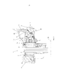
фиг. 2 - схематичный вид в разрезе примера осуществления вдоль линии II-II в соответствии с фиг. 1, в одном варианте;FIG. 2 is a schematic sectional view of an embodiment along line II-II in accordance with FIG. 1, in one embodiment;
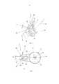
фиг. 3 - увеличенный частичный вид в перспективе приводного механизма регулировочного устройства примера осуществления в соответствии с фиг. 1;FIG. 3 is an enlarged partial perspective view of the drive mechanism of the adjusting device of the embodiment of FIG. one;
фиг. 4 - схематичный вид сверху на приводной механизм;FIG. 4 is a schematic plan view of a drive mechanism;
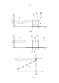
фиг. 5 - схематичная диаграмма характеристической кривой «давление - ход»,FIG. 5 is a schematic diagram of a pressure-stroke characteristic curve,
фиг. 5а - схематичная диаграмма сигнала датчика;FIG. 5a is a schematic diagram of a sensor signal;
фиг. 6 - схематичная диаграмма характеристической кривой датчика;FIG. 6 is a schematic diagram of a characteristic curve of a sensor;
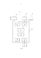
фиг. 7 - схематичная блок-схема устройства контроля воздушного зазора; иFIG. 7 is a schematic block diagram of an air gap control device; and
фи. 8 - структурная схема примера осуществления способа в соответствии с изобретением.fi. 8 is a structural diagram of an example embodiment of a method in accordance with the invention.
Фиг. 1 демонстрирует частичный вид в разрезе примера осуществления дискового тормозного механизма 1 в соответствии с изобретением с устройством 20 контроля воздушного зазора. На фиг. 2 представлен схематичный вид в разрезе примера осуществления вдоль линии II-II в соответствии с фиг. 1 в одном варианте.FIG. 1 shows a partial sectional view of an embodiment of a
Дисковый тормозной механизм 1 имеет тормозной диск 2 с осью 2а тормозного диска. Тормозной диск 2 перекрыт суппортом 4 дискового тормозного механизма, осуществленным в данном случае в виде плавающего суппорта. С обеих сторон тормозного диска 2 в данном случае расположено, соответственно, по тормозной накладке 3, соответственно, с держателем 3а тормозной накладки. Находящаяся на фиг. 1 и 2 с левой стороны тормозного диска 2 тормозная накладка 3 именуется тормозной накладкой 2 со стороны реакции, а расположенная с правой стороны тормозного диска 2 тормозная накладка 3 именуется тормозной накладкой 3 со стороны зажима.The
В данном примере осуществления дисковый тормозной механизм 1 осуществлен в виде двухпоршневого тормозного механизма с двумя шпиндельными узлами 5 и 5'. Каждый шпиндельный узел 5, 5' имеет резьбовой поршень 6, 6', который осуществлен в виде полого вала с наружной резьбой. В резьбовой поршень 6 шпиндельного узла 5 вставлено регулировочное устройство 10, на котором ниже мы остановимся более детально. Ось данного шпиндельного узла 5 обозначается, поэтому, как регулировочная ось 5а. Регулировочное устройство 10 снабжено регулировочным валом 5b, который без возможности вращения взаимодействует с резьбовым поршнем 6.In this embodiment, the
Другой шпиндельный узел 5' имеет ось, которая обозначена как передающая ось 5'а, а также предающий вал 5'b, который вставлен в резьбовой поршень 6' другого шпиндельного узла 5', и находится в соединении с резьбовым поршнем 6' без возможности вращения.The
Держатель 3а тормозной накладки со стороны зажима соединен со шпиндельными узлами 5, 5' через упоры 6а, 6'а, которые расположены на концах резьбовых поршней 6, 6'. Другой держатель 3а тормозной накладки со стороны реакции установлен на другой стороне тормозного диска в суппорте 4 дискового тормозного механизма. Резьбовые поршни 6, 6', соответственно, с возможностью поворота, своими наружными резьбами расположены в резьбовых отверстиях траверсы 7, которая обозначается также как перемычка. Резьба осуществлена в данном случае с подъемом в зоне самоторможения. За счет поворотного движения резьбовых поршней 6, 6' в траверсе 7 изменяется аксиальное положение резьбовых поршней 6, 6' относительно траверсы 7. Под термином «аксиальное положение» в данном случае понимается положение резьбовых поршней 6, 6' в аксиальном направлении оси 2а тормозного диска и осей 5а, 5'а. Оси 5а, 5'а проходят в данном случае параллельно оси 2а тормозного диска.The holder of the
Траверса 7 и резьбовые поршни 6, 6' выполнены с возможность приведения в действие посредством зажимного устройства, в данном случае тормозного рычага 8 с поворотной осью 8е (см. фиг. 2) под прямым углом к оси 2а тормозного диска 2. Тормозной рычаг 8 имеет корпус 8d рычага, который через опорные участки находится во взаимодействии с траверсой 7.The
Траверса 7 выполнена с возможностью смещения в направлении оси 2а тормозного диска посредством тормозного рычага 8. Движение к тормозному диску 2 обозначается как движение зажима, а движение в противоположном направлении именуется движением отпуска. Не поясненная более детально возвратная пружин 7а помещена в середине траверсы 7 в соответствующее углубление на стороне траверсы 7 со стороны накладки и опирается о суппорт 4 дискового тормозного механизма. Посредством возвратной пружины 7а траверса 7 при движении отпуска перемещается в представленное на фиг. 1 и на фиг. 2 положение отпуска дискового тормозного механизма 1.The
Расстояние между тормозными накладками 3 и тормозным диском 2 в положении отпуска обозначается как воздушный зазор. Вследствие износа накладок и диска этот воздушный зазор становится больше. Если это не компенсируется, то дисковый тормозной механизм 1 не может достичь своей максимальной мощности, так как ход механических элементов управления, то есть, в данном случае управляющий ход или поворотный угол тормозного рычага 8, увеличен.The distance between the
Дисковый тормозной механизм 1 может иметь различные силовые приводные механизмы. Тормозной рычаг 8 в данном случае приводится в действие, к примеру, пневматически. Для этого тормозной рычаг 8 имеет рукоятку 8b, которая соединена с корпусом 8d рычага (фиг. 2). На свободном конце рукоятки 8b расположен участок 8c подачи усилия, который взаимодействует с источником энергии, к примеру, с пневматическим цилиндром. Касательно конструкции и функционирования пневматического дискового тормозного механизма 1 ссылаются на соответствующее описание DE 19729024 С1.The
Регулировочное устройство 10 образовано для регулировки износа заранее установленного воздушного зазора, который обозначается как номинальный воздушный зазор. Под термином «регулировка» следует понимать уменьшение воздушного зазора. Заранее установленный воздушный зазор определен геометрией дискового тормозного механизма 1 и имеет так называемый конструктивный воздушный зазор. Иными словами, регулировочное устройство 10 уменьшает имеющийся воздушный зазор, если он слишком велик по отношению к заранее установленному воздушному зазору.An
Регулировочное устройство 10 расположено на шпиндельном узле 5, соосно с ним, с его резьбовым поршнем 6 и регулировочной осью 5а. Конструктивные элементы и функциональные группы регулировочного устройства 10, которое подробно описано, к примеру, в документе DE 102004037771 А1, расположены вокруг регулировочного вала 5b в аксиальном направлении и, таким образом, в направлении регулировочной оси 5а. Регулировочной устройство 10 своим концом со стороны зажима не поясненным более детально образом установлено в суппорте 4 дискового тормозного механизма. Для этого ссылаются на документ DE 102004037771 А1. На конце регулировочного вала 5b со стороны зажима без возможности вращения установлено синхронизирующее колесо 11а синхронизатора 11. Посредством синхронизатора 11, который еще будет описан ниже, регулировочный вал 5b находится в рабочем соединении с передающим валом 5'b передающего устройства.The adjusting
В другом шпиндельном узле 5' передающее устройство своим передающим валом 5'b расположено соосно со шпиндельным узлом 5', с его резьбовым поршнем 6' и передающей осью 5'а. В концевой зоне передающего вала 5'b со стороны зажима, как и у регулировочной оси 5b, синхронизирующее колесо 11'а синхронизатора 11 установлено без возможности вращения. Конец передающего вала 5'b со стороны зажима соединен в данном случае с датчиком 12 износа, который расположен в кожухообразном корпусе над концом передающего вала 5'b со стороны зажима на суппорте 4 дискового тормозного механизма. Датчик 12 износа через передающий вал 5'b без возможности вращения соединен с резьбовым поршнем 6'. Приемным элементом датчика износа может быть, к примеру, угловой датчик, к примеру, потенциометр. Он регистрирует угловое положение резьбового поршня 6' вокруг передающей оси 5'а. Оценка данного углового положения позволяет сделать вывод о состоянии износа тормозных накладок 3 и тормозного диска 2, так как резьбовой поршень 6' через передающий вал 5'b и, таким образом, через поясняемый далее более детально синхронизатор 11, соединен с резьбовым поршнем 6. Таким образом, датчик 12 износа служит для регистрации хода регулировки, то есть, состояния износа, и в данном случае посредством снабженного разъемом 13 соединительного провода 13а (электропроводящего или оптикопроводящего) соединен с устройством 19 управления тормозным механизмом, которое, в частности, может производить оценку зарегистрированного датчиком 12 износа измеренного значения.In another
Датчик 12 износа находится, кроме того, в соединении и с устройством 20а управления устройства 20 контроля воздушного зазора. Это будет пояснено далее более детально.The
Обычные пневматические дисковые тормозные механизмы 1, описанные, к примеру, в DE 19729024 С1, имеют регулировочное устройство 10 совместно с передающим устройством, в качестве интегрированных, автоматически функционирующих устройств регулировки износа. Посредством механической юстировки положения резьбовых поршней 6, 6' в траверсе 7 предшествующий износ пар трения тормозных накладок 3 и тормозного диска 2 компенсируется и, благодаря этому, поддерживается заранее установленный воздушный зазор.Conventional
Движение юстировки регулировочного устройства 10 осуществляется за счет побочной функции тормозного рычага 8 посредством приводного пальца 8а (или нескольких пальцев). Тормозной рычаг 8 приводится в действие, как уже упомянуто выше, к примеру, посредством тормозного цилиндра (пневматически, гидравлически, электрически).The adjustment movement of the adjusting
Так регулировочное устройство 10 через приводной механизм 9 находится во взаимодействии с тормозным рычагом 8. Приводной механизм 9 включает в себя исполнительный элемент, который осуществлен в виде соединенного с тормозным рычагом 8 приводного пальца 8а, а также палец 10b переключающей вилки приводного элемента 10а регулировочного устройства 10. Приводной механизм 9 будет описан далее более детально в связи с фиг. 3 и 4.Thus, the adjusting
При приведении в действие регулировочного устройства 10 посредством приводного механизма 9 с помощью тормозного рычага 8, приводится в действие, к примеру, муфта свободного хода регулировочного устройства 10, которая, к примеру, через фрикционную предохранительную муфту соединена с регулировочным валом 5b. Подробное описание функционирования регулировочного устройства 10 можно заимствовать из документа DE 102004037771 А1.When actuating the adjusting
Движение юстировки одного резьбового поршня 6, которое является также вращательным или поворотным движением регулировочного вала 5b, посредством синхронизатора 11 передается на передающий вал 5'b и, таким образом, на другой резьбовой поршень 6'. Для этого регулировочный вал 5b регулировочного устройства 10 и передающий вал 5'b передающего устройства посредством синхронизатора 11 соединены таким образом, что поворотное движение резьбового поршня 6 вокруг регулировочной оси 5а вызывает соответствующее поворотное движение резьбового поршня 6' вокруг передающей оси 5'а и наоборот. Синхронизатор 11 в представленном на фиг. 1 примере расположен на концах регулировочного вала 5b и передающего вала 5'b со стороны зажима. В варианте в соответствии с фиг. 2 синхронизатор 11 находится на стороне зажима траверсы 7. Синхронизатор 11 включает в себя синхронизирующее колесо 11а, которое соединено с резьбовым поршнем 6 шпиндельного узла 5 и с регулировочным валом 5b регулировочного устройства 10, другое синхронизирующее колесо 11'а, которое соединено с резьбовым поршнем 6' другого шпиндельного узла 5' и с передающим валом 5'b передающего устройства, а также синхронизирующее средство 11b, с которым соединены синхронизирующие колеса 11а и 11'а. В данном примере осуществления синхронизирующим средством 11b является тяговое средство, в предложенном на рассмотрение примере цепь. Так синхронизирующие колеса 11а, 11'а осуществлены в виде цепных колес. Тем самым, обеспечивается синхронное движение резьбовых поршней 6, 6' шпиндельных узлов 5 и 5' в процессе регулировки износа (приведенных в действие посредством регулировочного вала 5b регулировочного устройства 10) и регулировки в процесс работ по техническому обслуживанию, к примеру, замене накладок, (ручной привод, к примеру, через управляющий конец регулировочного вала 5b регулировочного устройства 10, что не изображенное, однако, можно легко представить).The alignment movement of one threaded
На фиг. 3 представлен увеличенный частичный вид в перспективе приводного механизма 9 регулировочного устройства 10 примера осуществления в соответствии с фиг. 1. Фиг. 4 демонстрирует, к тому же, схематичный вид сверху приводного механизма 9.In FIG. 3 is an enlarged partial perspective view of the
Слева на фиг. 3 корпус 8d тормозного рычага 8 обозначен лишь схематично, причем справа частично показано регулировочное устройство 10 с регулировочной осью 5а шпиндельного узла 5. На корпусе 8d рычага в данном случае установлены два приводных пальца 8а в форме цапф или стержней, которые в данном случае находятся в зацеплении с тремя пальцами 10b переключающей вилки приводного элемента 10а регулировочного устройств 10, причем приводные пальцы 8 а в данном случае расположены, соответственно, в выемке 15 между двумя пальцами 10b переключающей вилки. Фиг. 4 демонстрирует на виде сверху расположение приводного пальца 8а в выемке 15 между двумя пальцами 10b переключающей вилки.On the left in FIG. 3, the
Ось 8е тормозного рычага, вокруг которой тормозной рычаг 8 может поворачиваться, проходит под прямым углом к регулировочной оси 5а (см. также фиг. 2), Поворотное движение тормозного рычага 8 приводит затем к поворотному движению вверх приводного пальца 8а, которое передается на фиг. 4 в направлении вверх (обозначено посредством стрелки зажима hz) или вниз (обозначено посредством стрелки отпуска hl), причем это поворотное движение передается на палец 10b переключающей вилки и, таким образом, на приводной элемент 10а регулировочного устройства 10.The axis of the
В нерабочем положении, то есть, в положении отпуска, как представлено на фиг. 3 и 4, между рабочим контуром приводного пальца 8а и стенкой 15b пальца 10b переключающей вилки приводного элемента 10а регулировочного устройство 10 предусмотрен зазор или свободный ход 14. Этот свободный ход представляет собой, с учетом передаточных отношений на тормозном рычаге 8, конструктивный воздушный зазор дискового тормозного механизма 1. Иными словами, приведение в действие регулировочного устройства 10а осуществляется только после того, как траверса 7 при зажиме дискового тормозного механизма 1, то есть, при приведении в действие тормозного механизма, посредством поворотного движения тормозного рычага 8 оказывается смещена на большее расстояние, чем конструктивный воздушный зазор на тормозном диске 2.In the idle position, that is, in the vacation position, as shown in FIG. 3 and 4, between the working contour of the
В не зависимости от соответствующего конструктивного исполнения регулировочного устройства 10, которое обозначено в данном случае лишь примерно, конструктивно установленный воздушный зазор при этом всегда определен свободным ходом 14 в кинематической цепи между тормозным рычагом 8 и муфтой свободного хода регулировочного устройства 10, причем муфта свободного хода соединена с приводным элементом 10а. При зажиме этот свободный ход 14 проходится сначала в направлении зажима hz, причем не происходит никакой передачи движения через палец 10b переключающей вилки на регулировочное устройство 10. При этом не производится также никакой регулировки или юстировки, вследствие чего гарантирован минимальный воздушный зазор дискового тормозного механизма 1. То есть, свободный ход 14 в механических средствах приведения в действия прямо пропорционален воздушному зазору.Regardless of the corresponding design of the adjusting
Как только приводной палец 8а касается стенки 15b переключающей вилки, движение передается на палец 10b переключающей вилки, вследствие вхождения в зацепления с приводным пальцем 8а, в результате чего имеет место поворотное движение nz по часовой стрелке приводного элемента 10а регулировочного устройства 10. Это поворотное движение передается от соединенной с приводным элементом 10а муфты свободного хода на регулировочный вал 5b, причем происходит уменьшение воздушного зазора.As soon as the
При отпуске дискового тормозного механизма 1 тормозной рычаг 8 поворачивается обратно, причем приводной палец 8а передвигается в направлении отпуска hl. При этом он входит в контакт с другой стенкой 15а переключающей вилки и поворачивает, таким образом, приводной элемент 10а в направлении поворота nl против часовой стрелки. Так как приводной элемент 10а соединен с муфтой свободного хода регулировочного устройства 10, то это движение не передается на регулировочный вал 5b (это было бы в данном случае увеличением воздушного зазора, что не является желательным).When the
Регулировочное или котировочное движение для уменьшения воздушного зазора, которое осуществляет регулировочный вал 5b, через синхронизатор 11, как описано выше, передается на передающий вал 5'b, а также на датчик 12 износа. Датчик 12 износа вырабатывает, в зависимости от углового положения передающего вала 5'b, пропорциональный угловому положению, электрический сигнал (аналоговый или цифровой), который используется в электрическом/электронном устройстве, к примеру, в устройстве 19 управления тормозным механизмом, в качестве меры износа тормозных накладок 3, а также тормозного диска 2 дискового тормозного механизма 1, для постоянной регистрации износа пары трения (тормозные накладки 3 и тормозной диск 2). Таким образом, метрологически может быть определена прогрессирующая с износом юстировка (выдвигание, регулировка) резьбовых поршней 6, 6'. Это электрическое/электронное устройство базируется, к примеру, на измерении пути регулировки, то есть, угла поворота, резьбовых поршней 6, 6' с помощью потенциометра, который интегрирован в каждый колесный тормоз соответствующего транспортного средства. Измеренные значения подвергаются контролю, в соответствии с ситуацией на колесной паре, в блоке оценки результатов и при достижении заданного значения износа или предельного значения (в соответствии с выдвинутым или отрегулированным состоянием резьбовых поршней 6, 6') производится уведомление, к примеру, посредством акустического или/и оптического предупредительного сигнала.The adjustment or quotation movement to reduce the air gap that the
Посредством устройства 20 контроля воздушного зазора в соответствии с изобретением распознаются и визуализируются недопустимые отклонения воздушного зазора от заранее установленных значений. Устройство 20 включает в себя устройство 20а управления (фиг. 1), которое ниже будет описано более детально. Устройство 20а управления соединено с датчиком 12 износа и с устройством 19 управления тормозным механизмом. При этом устройство 20а управления использует сигналы датчика 12 износа и устройства 19 управления тормозным механизмом.By means of the air
Прежде всего, предлагается описание взаимосвязи между зажимным усилием, воздушным зазором, регулировкой и датчиком 12 износа.First of all, a description of the relationship between clamping force, air gap, adjustment and wear
Фиг. 5 демонстрирует схематичную диаграмму характеристической кривой «давление/ход». Фиг. 5а демонстрирует, к тому же, схематичную диаграмму сигнала датчика.FIG. 5 shows a schematic diagram of a pressure / stroke characteristic curve. FIG. 5a also shows a schematic diagram of a sensor signal.
В схематичной диаграмме с фиг. 5 давление p в тормозной системе зажимного устройства дискового тормозного механизма 1 представлено на ординате выше хода h рычага (абсциссы). Давлением p в тормозной системе может быть, к примеру, давление воздуха пневматического цилиндра или/и гидравлического цилиндра, или зажимное усилие приводимого в действие посредством электродвигателя элемента управления тормозным устройством. Под ходом h рычага следует понимать ход тормозного рычага 8.In the schematic diagram of FIG. 5, the pressure p in the brake system of the clamping device of the
Фиг. 5а демонстрирует посредством такой же абсциссы ход h рычага, как и на фиг. 5. Над ходом h рычага в данном случае, однако, нанесено значение U сигнала 17 датчика 12 износа. В данном примере исходят из того, что датчик 12 износа имеет потенциометр в качестве приемного элемента, то есть, изменяемое посредством вышеописанного поворота передающего вала 5'b электрическое сопротивление, на которое подается постоянное электрическое напряжение. Значением U сигнала в данном примере является в этом случае электрическое напряжение, которое может быть снято на приемном элементе и которое пропорционально повороту передающего вала 5'b. То есть, значение U сигнала в виде электрического напряжения пропорционально регулировке регулировочного устройства 10. Значение U сигнала изменяется лишь тогда, когда происходит регулировка.FIG. 5a shows, by the same abscissa, the lever travel h, as in FIG. 5. Over the lever stroke h in this case, however, the U value of the
Ссылочной позицией 16 на фиг. 5 обозначена примерная характеристическая кривая «давление - (усилие -) ход» тормозного механизма, к примеру, дискового тормозного механизма 1. Тормозной цилиндр взаимодействует с тормозным рычагом 8.
Процесс приведения в действие зажимного устройств включает в себя зажим и отпуск. В нерабочем состоянии (давление в тормозной системе = 0) тормозной цилиндр и тормозной рычаг 8, за счет расположенных внутри обратных пружин 7а, находятся в представленном на фиг. 1 и 2 исходном положении или в положении отпуска. При увеличении давления p в тормозной системе или отдаче усилия тормозного цилиндра, к примеру, (не изображенный) поршневой шток, во взаимодействии с участком 8c подачи усилия (фиг. 2), передвигает тормозной рычаг 8, а он зажимные элементы (траверсу 7 с резьбовыми поршнями 6, 6') в суппорте 4 дискового тормозного механизма. Как только преодолен конструктивный воздушный зазор, который именуется также номинальным воздушным зазором, (свободный ход 14 на фиг. 3 и 4), приводной палец 8а тормозного рычага 8 касается пальца 10b переключающей вилки приводного элемента 10а с муфтой свободного хода регулировочного устройства 10. Такая ситуация имеет место при ходе h0 рычага.The actuation process of the clamping devices includes clamping and tempering. In the idle state (pressure in the brake system = 0), the brake cylinder and
При зажиме давление p в тормозной системе в зоне перекрытия воздушного зазора увеличивается до значения хода h0 рычага с относительно небольшим подъемом кривой 16. В этой зоне воздушный зазор перекрывается. Воздушный зазор соответствует, тем самым, ходу h рычага от нулевой точки до значения хода h0 рычага. В этой точке R0 трения кривая 16 давления p в тормозной системе пересекает параллель к ординате, которая проходит через ход h0 рычага. При ходе h0 рычага кривая 16 назначена давлению p0 в тормозной системе.When clamping, the pressure p in the brake system in the area of overlap of the air gap increases to a stroke value h 0 of the lever with a relatively small rise in
«Точкой трения» является точка, в которой тормозные накладки 3 прилегают к тормозному диску 2 дискового тормозного механизма 1. Дальнейший зажим (участок 16а зажима) вызывает затем, за счет прижима тормозных накладок 3 с нарастающим усилием к тормозному диску 2, процесс торможения или замедления, причем давление p в тормозной системе на участке 16а зажима сильно возрастает. Отпуск зажимного устройства (за счет уменьшения давления p в тормозной системе) способствует перемене направления вышеописанного процесса.“Friction point” is the point at which the
Фиг. 6 представляет схематичную диаграмму характеристической кривой 18 датчика. При этом значение U сигнала, к примеру, электрическое напряжение, нанесено на ординату над значением общего износа GV на абсциссе. Общий износ GV относится к паре трения тормозных накладок 3 и тормозного диска 2. У новых пар трения износ пока отсутствует и исходное значение задается как значение Ua сигнала. Характеристическая кривая 18 датчика имеет в данном случае линейную форму и проходит с определенным подъемом от исходного значения Ua к конечному значению Ub, которому назначено значение общего износа GVa. При общем износе GVa необходима замена, по меньшей мере, тормозных накладок 3, и граница износа достигнута. На это указывает скачок напряжения на значении Uc сигнала, для чего датчик 12 износа осуществлен соответствующим образом. Значение Ua сигнала в качестве исходного значения имеет, к примеру, напряжение около 0,8 В. Общий износ GVa достигается при напряжении при значении Ub сигнала около 3,5 В. Затем происходит скачок напряжения до значения Uc сигнала, которое составляет примерно 4 B. Естественно, могут использоваться и другие значения напряжения или же значения тока (или же другие значения) в качестве значений U сигнала.FIG. 6 is a schematic diagram of a sensor
Производится распознавание случаев. Сначала рассматривается случай, при котором фактическая точка трения совпадает с заданной точкой трения. При этом, в соответствии с фиг. 5, точка R0 трения совпадает с ходом h0 рычага, и регулировка посредством регулировочного устройства 1 не производится. Этот случай имеет место тогда, когда, к примеру, тормозные накладки 3 новые или регулировка произведена на предыдущем процессе торможения. Это означает, что фактический воздушный зазор соответствует заранее заданному воздушному зазору, и в регулировке нет необходимости. То есть, регулировка не производится. Тормозные накладки 3 располагаются уже на тормозном диске 2, и давление p в тормозной системе на участке торможения 16а сильно возрастает.Case recognition is performed. First, a case is considered in which the actual friction point coincides with a given friction point. Moreover, in accordance with FIG. 5, the friction point R 0 coincides with the stroke h 0 of the lever, and adjustment by the adjusting
К этому фиг. 5а демонстрирует соответствующий сигнал 17 датчика, который в положении покоя дискового тормозного механизма 1, то есть при не приведенном в действие зажимном устройстве, и при приведении в действие до момента преодоления конструктивного воздушного зазора вплоть до достижения хода h0 рычага, имеет постоянное значение. Это представлено на фиг. 5а посредством значения U0 сигнала. Значение U0 сигнала соответствует, таким образом, значению регулировки, которое происходит от регулировки, осуществленной в последний раз, или при наличии новых тормозных накладок 3 образует исходное значение.To this FIG. 5a shows the corresponding
Дальнейшее движение приводного пальца 8а при увеличивающемся давлении p в тормозной системе на участке 16а торможения передается именно на палец 10b переключающей вилки приводного элемента 10а регулировочного устройства 10 (фиг. 3, 4), однако, имеющаяся в регулировочном устройстве 10 предохранительная муфта срабатывает, так как тормозные накладки 3 уже прилегают к тормозному диску 2. Приводной элемент 10а осуществляет затем движение относительно неподвижного регулировочного вала 5b. Таким образом, регулировка не производится. Регулировочный вал 5b и соединенный с ним через синхронизатор 11 передающий вал 5b с присоединенным к нему датчиком 12 износа не меняют положения.Further movement of the
Сигнал 17 датчика, таким образом, не изменяется и остается постоянным на уровне значения U0 сигнала.The
Далее фиг. 5 демонстрирует также случаи, при которых фактическая точка трения не совпадает с заданной точкой трения при ходе h0 рычага. Сначала рассматривается случай, при котором воздушный зазор, ввиду износа тормозных накладок 3 в ходе осуществленных ранее процессов торможения, стал больше. То есть, фактическая точка трения сместилась к большему значению регулировочного хода h рычага. Эта фактическая точка трения представлена в данном случае как точка R1 трения при ходе h1 рычага. Ход h1 рычага при этом больше, чем предыдущий ход h0 рычага, что обусловлено тем, что, ввиду износа тормозных накладок 3, должен быть перекрыт больший воздушный зазор, а именно, конструктивный воздушный зазор, до хода h0 рычага и затем обусловленный износом воздушный зазор до хода h1 рычага. При достижении этой точки R1 трения с соответствующим давлением p1 в тормозной системе давление p в тормозной системе сильно возрастает на участке 16b зажима, который переместился на фиг. 5 вправо.Next, FIG. 5 also demonstrates cases in which the actual friction point does not coincide with the predetermined friction point during the lever stroke h 0 . First, we consider the case in which the air gap, due to wear of the
При достижении хода h0 рычага с соответствующим давлением p0 в тормозной системе фактическая точка R1 трения, однако, еще не достигается. Теперь приводится в действие регулировочное устройство 10, так как тормозные накладки 3 еще не прилегают к тормозному диску 2 и, таким образом, предохранительная муфта регулировочного устройства 10 не срабатывает. Дальнейшее движение приводного пальца 8а при увеличивающемся давлении p>p0 в тормозной системе снова передается на палец 10b переключающей вилки приводного элемента 10а регулировочного устройства 10 (фиг. 3, 4). Приводной элемент 10а поворачивает регулировочный вал 5b посредством муфты свободного хода. Таким образом, производится регулировка. Регулировочный вал 5b и соединенный с ним через синхронизатор 11 передающий вал 5'b с присоединенным к нему датчиком 12 износа смещаются. Это демонстрируется на фиг. 5а посредством участка 17а регулировки сигнала 17 датчика, который с определенным наклоном уходит вверх.Upon reaching the lever stroke h 0 with the corresponding pressure p 0 in the brake system, the actual friction point R 1 , however, has not yet been reached. The
При этом значение U0 сигнала, которое назначено значению хода h0 рычага, изменяется на новое значение U1 сигнала при значении хода h1 рычага. В представленном примере U1 больше, чем U0, однако, в другом варианте осуществления возможна и обратная ситуация. После того, как регулировка до заранее заданного значения воздушного зазора в точке R1 трения осуществлена, значение U1 сигнала соответствует фактическому износу тормозных накладок 3 и тормозного диска 2. Это значение U1 сигнала остается постоянным до изменения посредством последующей регулировки. Это демонстрирует участок 17b постоянного сигнала, начиная со значения хода h1 рычага на фиг. 5а.In this case, the signal value U 0 , which is assigned to the lever travel value h 0 , changes to the new signal value U 1 at the lever travel value h 1 . In the presented example, U 1 is greater than U 0 , however, in another embodiment, the opposite is also possible. After the adjustment to the predetermined air gap value at the friction point R 1 is carried out, the signal value U 1 corresponds to the actual wear of the
В другом случае приводной элемент 10а регулировочного устройства 10 посредством своего пальца 10b переключающей вилки (фиг. 3, 4), к примеру, вследствие ошибки, вращательного движения (на фиг. 4 с поворотом nl против часовой стрелки) против своего функционально заданного направления вращения, может производить поворот nz (то есть против направления зажима соединенной с приводным элементом 10а муфты свободного хода). Таким образом, необходимый свободный ход 14 в процессе регулировки уменьшается. В результате при последующем торможении получаем точку R2 трения при ходе h2 рычага, причем ход h2 рычага короче, чем ход h0 рычага. При этом торможение (участок 16c торможения) происходит даже перед достижением конструктивного воздушного зазора при давлении p0 в тормозной системе и ходе h0 рычага. После дальнейших торможений выявляется износ, который затем уже в точке R2 трения регулируется вышеописанным образом. Посредством такой, соответственно досрочной, регулировки формируется нежелательно уменьшенный воздушный зазор.In another case, the
Также датчик 12 износа при более раннем контакте пальца 10b переключающей вилки с приводным пальцем 8а (фиг. 3, 4) при ходе h2 рычага, соответственно, поворачивается раньше и изменяет значение U0 сигнала теперь уже при более коротком ходе h2 рычага на участке 17'а сигнала на уже возникающий при ходе h0 рычага участок 17'b постоянного сигнала. Это поясняется на фиг. 5a штриховыми линиями с двойным пунктиром для 17'а и 17'b.Also, the
В устройстве 19 управления тормозным механизмом (к примеру, в электронной тормозной системе EBS) имеются в распоряжении значения р0, р1, р2 (и естественно, другие) давления в тормозной системе, которые заданы при соответствующем ходе h0, h1, h2 рычага в тормозном цилиндре. Это выявляется из характеристической кривой «давление - ход» тормозного цилиндра, которая сохранена в памяти устройства 19 управления тормозным механизмом в качестве контрольного значения или/и в запоминающем устройстве 21 устройства 20 контроля воздушного зазора (см. фиг. 7). Упрощенная, аналогичная характеристическая кривая 16 представлена на фиг. 5. Таким образом, имеется, соответственно, пара значений р/u из давления p в тормозной системе и сигнала 17 срабатывания датчика 12 износа. Под термином «сигнал срабатывания датчика» следует понимать значение U сигнала 17 датчика 12 износа, включая временную характеристику значения U сигнала. Это будет пояснено далее.In the
При этом для вышеупомянутых трех случаев необходимо различать следующее.Moreover, for the above three cases, it is necessary to distinguish the following.
В первом случае, когда при достижении точки R0 трения с давлением р0 в тормозной системе при ходе h0 рычага регулировка не производится, так как фактический воздушный зазор соответствует номинальному воздушному зазору, пара значений p/u состоит из давления р0 в тормозной системе и сначала постоянного значения U0 сигнала датчика 12 износа. Сигналом срабатывания датчика является в данном случае постоянное значение U0 сигнала.In the first case, when upon reaching the friction point R 0 with the pressure p 0 in the brake system during the lever stroke h 0, adjustment is not made, since the actual air gap corresponds to the nominal air gap, the pair of p / u values consists of the pressure p 0 in the brake system and first, a constant value U 0 of the signal of the
Во втором случае имеется износ, фактическая точка R0 трения с соответствующим давлением p1 в тормозной системе достигается только после перекрытия номинального воздушного зазора после прохождения давлением р0 в тормозной системе без прохождения участка 16а торможения и без сильного увеличения давления p в тормозной системе.In the second case, there is wear, the actual friction point R 0 with the corresponding pressure p 1 in the brake system is reached only after the nominal air gap is closed after passing pressure p 0 in the brake system without passing through the
При этом, однако, происходит регулировка, которая начинается при давлении р0 в тормозной системе с ходом h0 рычага и имеет следствием изменение значения U сигнала 17 датчика 12 износа. В этом случае это изменение значения U сигнала 17 датчика является сигналом срабатывания датчика. Соответствующая пара значений p/u имеет в данном случае давление p1 в тормозной системе и сигнал срабатывания датчика U>U0.In this case, however, an adjustment occurs that begins at a pressure p 0 in the brake system with a lever stroke h 0 and results in a change in the U value of the
В третьем случае с давлением р2 в тормозной системе в точке R2 трения при ходе h2 рычага номинальный воздушный зазор (при давлении р0 в тормозной системе в точке R0 трения при ходе h0 рычага) выходит за границы нижнего предельного значения, причем давление р2 в тормозной системе, вследствие этого, в начале изменения значения U0 сигнала 17 датчика 12 износа меньше номинального давления р0 в тормозной системе (приложенного давления). Соответствующая пара значений р/u имеет в данном случае давление р2 в тормозной системе и сигнал срабатывания датчика U<U0.In the third case, with the pressure p 2 in the brake system at the friction point R 2 during the lever stroke h 2, the nominal air gap (at the pressure p 0 in the brake system at the friction point R 0 during the lever stroke h 0 ) goes beyond the lower limit value, and the pressure p 2 in the brake system, as a result, at the beginning of the change in the value U 0 of the signal 17 of the
Посредством сравнения этих значений можно установить, появляется ли сигнал срабатывания датчика значения U сигнала 17 датчика 12 износа перед, при, или после достижения соответствующего номинального давления р0 в тормозной системе в качестве приложенного давления.By comparing these values, it can be determined whether the sensor response signal U appears on the
Эта разность между номинальным давлением р0 в тормозной системе (приложенное давление) и фактическим давлением p в тормозной системе при возникновении сигнала срабатывания датчика перед достижением номинального давления р0 в тормозной системе может быть положена в основу в качестве спускового элемента для запуска предупредительного сигнала или другого мероприятия.This difference between the nominal pressure p 0 in the brake system (applied pressure) and the actual pressure p in the brake system when a sensor triggers a signal before reaching the nominal pressure p 0 in the brake system can be used as a trigger for triggering an alarm or other Events.
Такой контроль воздушного зазора производится посредством устройства 20 контроля воздушного зазора. Для этого фиг. 7 демонстрирует схематичную блок-схему устройства 20 контроля воздушного зазора.Such air gap control is performed by the air
На транспортном средстве устройство 20 контроля воздушного зазора предусмотрено для каждого колесного тормоза, к примеру, у грузового автомобиля с тремя осями для шести колесных тормозов.On the vehicle, an air
Устройство 20 контроля воздушного зазора включает в себя в данном примере устройство 20а управления, датчик 12 износа и сигнальный блок 26. Кроме того, в данном примере осуществления ему назначено устройство 19 управления тормозным механизмом, с которым соединено устройство 20а управления. Вместо устройства 19 управления тормозным механизмом или в дополнение к нему, к устройству 20а управления, разумеется, могут быть подсоединены и соответствующие датчики. Этими датчиками могут быть, к примеру, датчик ножного тормоза для регистрации торможения, датчик давления или/и усилия для регистрации зажимного усилия или давления p в тормозной системе, датчик хода рычага или датчик хода поршня тормозного цилиндра для регистрации хода h рычага. Кроме того, характеристическая кривая тормозного цилиндра или/и дискового тормозного механизма 1 в качестве характеристической кривой «давление - ход», как, к примеру, характеристическая кривая 16 на фиг. 5, записывается в устройство 19 управления тормозным механизмом или в специальное запоминающее устройство, к примеру, в устройство 20а управления.The air
В качестве примера для регистрации дополнительных величин, которые возможно могут быт привлечены к оценке измеренных значений и полученных от устройства 20а управления величин, представлено устройство 27 регистрации температуры. Это может быть, к примеру, датчик температуры на каждом колесном тормозе соответствующего транспортного средства, который, соответственно, соединен с устройством 20а управления.As an example, for recording additional values that may possibly be involved in evaluating the measured values and the values obtained from the
Соединение с устройством 20а управления могут обеспечивать электрические или оптические линии передачи, однако, разумеется, возможны и беспроводные соединения, к примеру, от каждого колесного тормоза транспортного средства к центральному сигнальному блоку 26.Electrical or optical transmission lines may provide a connection to the
Устройство 20а управления включает в себя в данном примере запоминающее устройство 21, блок 22 распознавания, блок 23 сравнения, блок 24 оценки результатов и блок 25 вывода.The
Запоминающее устройство 21 служит для сохранения, в частности, заранее устанавливаемых значений, к примеру, табличных значений и/или характеристических кривых соответствующего тормозного цилиндра и датчика 12 износа. Характеристическая кривая «давление - ход» соответствующего тормозного цилиндра может быть, однако, записана в запоминающее устройство 21 и посредством так называемого самостоятельного изучения. Это может происходить, к примеру, при новом режиме дискового тормозного механизма 1. То же самое относится и к характеристическим кривым датчиков 12 износа. В память запоминающего устройства 21 могут быть записаны, разумеется, и другие значения в качестве контрольных значений, предельных значений и проч. Запоминающее устройство 21 соединено с блоком 23 сравнения.The
Запоминающее устройство 21 служит также для сохранения зарегистрированных датчиком 12 износа значений, или посредством (не изображенного) прямого соединения с ним или, к примеру, через устройство 19 управления тормозным механизмом.The
Блок 22 распознавания соединен с датчиком 12 износа. Он регистрирует фактическое значение U сигнала 17 датчика 12 износа. Кроме того, блок 22 распознавания присоединен к блоку 23 сравнения и предоставляет в распоряжение блока 23 сравнения зарегистрированное значение U сигнала в соответствующей форме, к примеру, в виде цифрового сигнала.The recognition unit 22 is connected to the
Блок 23 сравнения образует посредством фактических значений р давления в тормозной системе из устройства 19 управления тормозным механизмом или других, не представленных датчиков и посредством полученных от блока 22 распознавания фактических значений U сигнала фактические пары значений p/U. Блок 23 сравнения сопоставляет их с табличными значениями или со значениями характеристических кривых из запоминающего устройства 21 или/и из устройства 19 управления тормозным механизмом. Блок 23 сравнения передает свои результаты сравнения на блок 24 оценки результатов, с которым он соединен.The
Блок 24 оценки результатов производит оценку полученных от блока 23 сравнения данных, причем возвращает их также на запоминающее устройство 21 (что не изображено). В зависимости от результатов оценки блок 24 оценки результатов активирует связанный с ним блок 25 вывода таким образом, что он передает его значения, предупреждения, информацию с соответствующими указаниями на вывод. Кроме того, блок 24 оценки результатов соединен со следующим запоминающим устройством 21а, в памяти которого, к примеру, фактическое значение U сигнала временно или для других применений может быть сохранено. Разумеется, и другие значения могут быть записаны или/и сохранены в памяти запоминающего устройство 21а.The
Блок 25 вывода подготавливает полученную от блока 24 оценки результатов информацию для выявления или уведомления и передает ее в соответствующей форме на сигнальный блок 26.The
В процессе торможения, который через устройство 19 управления тормозным механизмом или, к примеру, посредством датчика ножного тормоза распознается устройством 20 контроля воздушного зазора, устройство 20 контроля воздушного зазора активируется.During braking, which is detected by the air
Образованные блоком 23 сравнения фактические пары значений p/U сравниваются с записанными в память запоминающего устройства 21 парами значений. При увеличении давления p в тормозной систем контролируют, началось ли до достижения номинального давления p0 в тормозной системе изменение постоянного значения U сигнала датчика 12 износа. Если это имеет место (U>U0), то через блок 24 оценки результатов на сигнальный блок 25 передается предупреждение для акустического, оптического, осязательного или/и буквенно-цифрового сообщения посредством сигнального блока 26 о том, что номинальное значение воздушного зазора ниже предельно допустимого.The actual pairs of p / U values formed by the
Когда номинальное давление р0 в тормозной системе достигнуто, сигнал срабатывания датчика не реализован и давление p в тормозной системе на участке 16а торможения (сохраненном в памяти запоминающего устройства) сильно возрастает, исходят из того, что регулировка не производится и воздушный зазор корректен.When the nominal pressure p 0 in the braking system is reached, the sensor response signal is not realized and the pressure p in the braking system in the
Когда номинальное давление р0 в тормозной системе достигнуто, сигнал срабатывания датчика регистрируется и давление p в тормозной системе возрастает не сильно, а сохраненная в памяти характеристическая кривая 16 проходит далее, посредством блока 24 оценки результатов сигнальному блоку 25 сообщается о том, что регулировка производится. При этом анализ регулировки может быть осуществлен также таким образом, что регулировка может быть незначительной, нормальной или значительной.When the nominal pressure p 0 in the brake system is reached, the sensor response signal is recorded and the pressure p in the brake system does not increase much, and the
Контроль воздушного зазора резюмирован в следующей таблице.Air gap control is summarized in the following table.

Фиг. 8 демонстрирует структурную схему примера осуществления способа в соответствии с изобретением для контроля воздушного зазора посредством вышеописанного устройства контроля воздушного зазора.FIG. 8 shows a block diagram of an example embodiment of a method in accordance with the invention for controlling an air gap by the above-described air gap control device.
При этом на первом этапе способа S1 фактические пары значений p/U образуются во время процесса торможения, причем производится регистрация значений U сигнала.Moreover, in the first step of method S1, actual pairs of p / U values are formed during the braking process, and the U signal values are recorded.
На втором этапе S2 способа фактические пары значений p/U сравниваются с сохраненными в памяти запоминающего устройства 21 парами значений.In the second step S2 of the method, the actual pairs of p / U values are compared with the pairs of values stored in the memory of the
И на основании этих сравнений на третьем этапе S3 способа производится оценка результатов с возможным уведомлением.And based on these comparisons, the third step S3 of the method evaluates the results with a possible notification.
При определенных рабочих состояниях дискового тормозного механизма 1 может являться целесообразным предотвращение слишком раннего или излишнего предупредительного сигнала. Когда, к примеру, воздушный зазор, вследствие термических воздействий, уменьшен лишь временно (р<р0 и U<U0) и после охлаждения снова нормализуется, в выработке предупредительного сигнала нет необходимости. Для этого устройство 20а управления может быть соединено с устройством 27 регистрации температуры. Устройством 27 регистрации температуры может быть, к примеру, отдельный датчик температуры на дисковом тормозном механизме 1 или значение температуры, которое выдает устройство 19 управления тормозным механизмом.Under certain operating conditions of the
В соответствии с характеристикой дискового тормозного механизма 1 и парами трения могут быть разработаны различные стратегии при оценке данных (пар значений p/U; температуры) посредством блока 24 оценки результатов. Так, к примеру, выдача предупреждения или предупредительного сигнала может быть установлена, к примеру, лишь после определенного количества измеренных значений или контрольных наблюдений (фактические пары значений p/U) за пределами допусков. Также определенная тенденция измеренных значений в фактических парах значений p/U может быть положена в основу уведомления (положительного, отрицательного или нейтрального).In accordance with the characteristic of the
В то время как регистрация и оценка пары значений p/U в любой момент работы дискового тормозного механизма 1 может производиться посредством устройства 20 контроля воздушного зазора, возможны, разумеется, различные принципы действия. Как временной момент, так и частота контроля воздушного зазора могут быть определены в зависимости от типа или варианта использования транспортного средства. Так, к примеру, контроль воздушного зазора может осуществляться во время остановки транспортного средства (посредством запуска автоматического зажима тормозного механизма или через сигнальный блок с требованием к водителю) или во время движения. Контроль воздушного зазора может производиться также только после определенного количества торможений или же непрерывно.While registration and evaluation of a pair of p / U values at any moment of operation of the
Вышеописанное согласование (пары значений p/U) давления (приложенное давление) в тормозной системе и сигнала срабатывания датчика в качестве значения U сигнала датчика 12 износа может быть выведено на основании характеристической кривой «давление - ход» используемого тормозного цилиндра и известных геометрических величин дискового тормозного механизма 1. Для более точной и специфической регистрации соответствующих данных тормозного механизма транспортного средства (суппорт 4 дискового тормозного механизма с тормозным цилиндром) возможно, к примеру, в новом режиме дискового тормозного механизма 1 запрограммировать давление начала срабатывании в систему или в устройство 20 контроля воздушного зазора. При этом при контролируемом увеличении давления р в тормозном цилиндре значение U сигнала датчика 12 износа подвергается контролю и давление р в момент срабатывания или же вся характеристическая кривая сохраняются в памяти.The above matching (pairs of p / U values) of the pressure (applied pressure) in the brake system and the sensor response signal as the value U of the
Другие параметры дискового тормозного механизма 1, учет которых предпочтителен для точности измерения в процессе контроля воздушного зазора, могут быть также запрограммированы и использованы в оценке измеренных значений. Так как датчик 12 износа обычно перемещается посредством механических передающих элементов (зубчатых колес, цепей и т.д.), то механический зазор оказывает воздействие на синхронное движение тормозного рычага 8 и датчика 12 износа и, тем самым, на сигнал 17 датчика. Суммарный зазор этих механических зазоров между приводным пальцем 8а тормозного рычага 8 и датчика 12 износа вызывает гистерезис в эпюре напряжений кривой сигнала 17 датчика при запуске (ходе торможения) и отпуске (обратном ходе). Этот гистерезис может быть измерен посредством измерения значений U сигнала 17 датчика при подаче воздуха в тормозной цилиндр и при отведении воздуха из тормозного цилиндра, сохранен в запоминающем устройства 21 и использован для корректировки данных измерений.Other parameters of the
Устройство 20 контроля воздушного зазора описано, к примеру, для определенного конструктивного типа дисковых тормозных механизмов 1.The air
Изобретение не ограничено вышеописанными примерами осуществления. Оно может быть модифицировано в рамках приложенной формулы изобретения.The invention is not limited to the above-described embodiments. It can be modified within the framework of the attached claims.
Так устройство 20 контроля воздушного зазора может быть использовано и для других конструктивных форм регулировочного устройства 10, приводного механизма 9 и электронных датчиков износа, так как функциональные основы действительны и в этом случае.So the
Использование барабанных тормозных механизмов также возможно, так как они частично также оснащены электронными системами регистрации износа и системами управления с системами управления торможением (EBS), и касательно принципов регулировки подчиняются тем же закономерностям.The use of drum brake mechanisms is also possible, as they are partially also equipped with electronic wear registration systems and control systems with braking control systems (EBS), and with regard to the principles of adjustment obey the same laws.
Возможно, чтобы на транспортном средстве предусмотренное для каждого колесного тормоза устройство 20 контроля воздушного зазора располагалось в центре транспортного средства, к примеру, у общего устройства 19 управления тормозным механизмом или в нем. Устройства 20 контроля воздушного зазора могут являться при этом элементами программного обеспечения устройства 19 управления тормозным механизмом.It is possible that on the vehicle the air
Claims (23)
Applications Claiming Priority (3)
| Application Number | Priority Date | Filing Date | Title |
|---|---|---|---|
| DE102013100786.4A DE102013100786A1 (en) | 2013-01-25 | 2013-01-25 | Disc brake with a Lüftspielüberwachungsvorrichtung and method for Lüftspielüberwachung |
| DE102013100786.4 | 2013-01-25 | ||
| PCT/EP2014/051401 WO2014114747A2 (en) | 2013-01-25 | 2014-01-24 | Disk brake having a clearance-monitoring device, and method for monitoring clearance |
Publications (2)
| Publication Number | Publication Date |
|---|---|
| RU2015135530A RU2015135530A (en) | 2017-03-03 |
| RU2644839C2 true RU2644839C2 (en) | 2018-02-14 |
Family
ID=50029019
Family Applications (1)
| Application Number | Title | Priority Date | Filing Date |
|---|---|---|---|
| RU2015135530A RU2644839C2 (en) | 2013-01-25 | 2014-01-24 | Disc brake mechanism with air clearance control device and air clearance control method |
Country Status (10)
| Country | Link |
|---|---|
| US (1) | US9958020B2 (en) |
| EP (1) | EP2948690B1 (en) |
| JP (1) | JP6426623B2 (en) |
| KR (1) | KR20150109371A (en) |
| CN (1) | CN105190077B (en) |
| BR (1) | BR112015016693A2 (en) |
| DE (1) | DE102013100786A1 (en) |
| MX (1) | MX358489B (en) |
| RU (1) | RU2644839C2 (en) |
| WO (1) | WO2014114747A2 (en) |
Families Citing this family (22)
| Publication number | Priority date | Publication date | Assignee | Title |
|---|---|---|---|---|
| DE102015100322A1 (en) * | 2015-01-12 | 2016-07-14 | Bpw Bergische Achsen Kg | Disc brake and drive element of an adjusting device of a disc brake |
| DE102015001152A1 (en) | 2015-02-02 | 2016-08-04 | Wabco Europe Bvba | Method for monitoring a brake for motor vehicles, brake system for carrying out the method and motor vehicle with such |
| US10570974B2 (en) | 2015-04-17 | 2020-02-25 | Goodrich Corporation | Brake position and wear detection systems and methods |
| DE102016001577A1 (en) * | 2016-02-11 | 2017-08-17 | Wabco Europe Bvba | A method for Lüftspielerkennung in a brake of a motor vehicle, in particular utility vehicle, controller and brake with selbigem |
| EP3251908B1 (en) * | 2016-06-03 | 2021-01-20 | Meritor Heavy Vehicle Braking Systems (UK) Limited | Brake system and method of control with air gap estimation |
| CN105937569B (en) * | 2016-06-17 | 2018-07-10 | 安徽机电职业技术学院 | A kind of adjustable brake block |
| US10800386B2 (en) | 2017-07-24 | 2020-10-13 | Goodrich Corporation | Brake position system |
| US10493962B2 (en) | 2017-07-24 | 2019-12-03 | Goodrich Corporation | Brake position system |
| EP3698065B1 (en) * | 2017-10-16 | 2021-05-26 | ZF CV Systems Europe BV | Brake device, particularly a utility vehicle disk brake |
| US10731720B2 (en) * | 2018-01-26 | 2020-08-04 | Rivian Ip Holdings, Llc | Methods, systems, and media for non-contact brake pad wear determination |
| DE102018210232A1 (en) * | 2018-06-22 | 2019-12-24 | Robert Bosch Gmbh | Method for controlling an electromechanical braking device in a vehicle |
| DE102018117574A1 (en) * | 2018-07-20 | 2020-01-23 | Knorr-Bremse Systeme für Nutzfahrzeuge GmbH | Disc brake with an electrical actuator and method for setting a defined air gap of a disc brake |
| DE102019100481A1 (en) * | 2019-01-10 | 2020-07-16 | Wabco Europe Bvba | Method for setting an air gap of an electromechanical brake and the relevant brake and control device |
| CN110790103B (en) * | 2019-11-11 | 2021-06-01 | 苏州科瞬电磁技术有限公司 | Test method |
| IT202000021220A1 (en) * | 2020-09-08 | 2022-03-08 | Alessio VARDIERO | BRAKING SYSTEM AND METHOD |
| CN112503121B (en) * | 2020-12-29 | 2022-03-15 | 焦作市虹桥制动器股份有限公司 | Electro-hydraulic tread brake |
| WO2022194427A1 (en) * | 2021-03-16 | 2022-09-22 | Eaton Intelligent Power Limited | Clutch system with wear indicator |
| DE102021203735A1 (en) | 2021-04-15 | 2022-10-20 | Continental Automotive Technologies GmbH | Method for determining wear parameters of a brake lining |
| CN114458708B (en) * | 2021-08-25 | 2024-03-26 | 苏州麦哲轮汽车电子科技有限公司 | Temperature sensing control system and control method for automobile brake caliper |
| CN114368378B (en) * | 2022-01-11 | 2022-10-14 | 中车大同电力机车有限公司 | Locomotive brake monitoring device and method |
| DE102022116576A1 (en) * | 2022-07-04 | 2024-01-04 | Zf Cv Systems Global Gmbh | Method for adjusting an application pressure of a vehicle brake and the relevant vehicle brake |
| DE102022125261A1 (en) * | 2022-09-30 | 2024-04-04 | Knorr-Bremse Systeme für Nutzfahrzeuge GmbH | Disc brake for a commercial vehicle |
Citations (5)
| Publication number | Priority date | Publication date | Assignee | Title |
|---|---|---|---|---|
| US4937554A (en) * | 1989-05-22 | 1990-06-26 | Paccar Inc. | Electronic brake monitoring system and method |
| EP0421066A1 (en) * | 1989-09-13 | 1991-04-10 | WABCO Vermögensverwaltungs-GmbH | Method and apparatus for estimating the mean temperature of a brake component |
| US6250434B1 (en) * | 1997-07-23 | 2001-06-26 | Knorr-Bremse Systeme Fur Nutzfahrzeuge Gmbh | Wear adjusting device for disk brakes and method for controlling the device |
| RU2384433C2 (en) * | 2004-06-24 | 2010-03-20 | Джи Эм Глоубал Текнолоджи Оперейшнз, Инк. | Braking system with integral electronic controller and function of "braking system pressure anticipatory increase", and method of baking electronic control |
| US7866447B2 (en) * | 2003-12-09 | 2011-01-11 | Knorr-Bremse Systeme Fuer Nutzfahrzeuge Gmbh | Disk brake, especially with an electromotive adjusting device, and method for controlling said type of disk brake |
Family Cites Families (35)
| Publication number | Priority date | Publication date | Assignee | Title |
|---|---|---|---|---|
| DE4017950A1 (en) | 1990-06-05 | 1991-12-12 | Wabco Westinghouse Fahrzeug | Vehicle brake operating device - uses detected play for adjustment of brake operating shaft relative to brake lever |
| EP0567155B1 (en) | 1992-04-24 | 1996-03-27 | DEUTSCHE PERROT-BREMSE GmbH | Wear surveillance device for a sliding caliper disc brake |
| US5339069A (en) * | 1992-07-01 | 1994-08-16 | Tripen Enterprises Ltd. | Brake monitoring system |
| SE504466C2 (en) * | 1995-06-08 | 1997-02-17 | Haldex Ab | Wear indication device for brake pads |
| DE19600819A1 (en) * | 1996-01-11 | 1997-07-17 | Perrot Bremsen Gmbh | Wear monitoring device |
| EP0877872B1 (en) * | 1996-02-07 | 2003-05-02 | Meritor Automotive, Inc. | Brake wear sensor |
| SE511562C2 (en) * | 1997-04-28 | 1999-10-18 | Volvo Lastvagnar Ab | Adjustment device for wear of brake pads |
| DE19729024C1 (en) | 1997-07-08 | 1999-01-28 | Knorr Bremse Systeme | Wear compensator for motor vehicle disc brake |
| US20020126007A1 (en) * | 1998-11-30 | 2002-09-12 | Weant Bob R. | Brake monitoring system |
| JP2000234641A (en) * | 1999-02-15 | 2000-08-29 | Toyota Motor Corp | Motor-driven brake device |
| DE19933962C2 (en) | 1999-07-20 | 2003-01-30 | Knorr Bremse Systeme | Device and method for monitoring electromechanical application device for vehicle brakes |
| US7600455B2 (en) * | 2000-08-14 | 2009-10-13 | Sd3, Llc | Logic control for fast-acting safety system |
| US6626269B2 (en) * | 2000-08-08 | 2003-09-30 | Delphi Technologies, Inc. | Zero drag disc brake with anti-knock-back device |
| US6581728B2 (en) * | 2001-02-08 | 2003-06-24 | Volvo Trucks North America, Inc. | Brake shoe proximity sensor |
| JP2003004075A (en) * | 2001-06-21 | 2003-01-08 | Akebono Brake Ind Co Ltd | Repairing method of life display device for brake element for vehicle |
| US7624849B2 (en) * | 2001-08-03 | 2009-12-01 | Goncalves Jorge M | Brake system |
| DE10138452B4 (en) | 2001-08-04 | 2014-07-17 | Wabco Gmbh | Method for Lüftspielnachstellung of disc brakes |
| US6637262B2 (en) * | 2001-11-02 | 2003-10-28 | Delphi Technologies, Inc. | Electrical wear sensor for disc brake |
| US20050241894A1 (en) * | 2002-02-13 | 2005-11-03 | Johann Baumgartner | Disc brake with an electric motor driven adjustment device and method for controlling a disk brake |
| DE10214669B4 (en) | 2002-04-03 | 2014-01-23 | Knorr-Bremse Systeme für Schienenfahrzeuge GmbH | Method and device for controlling an electrically operated wear adjustment device |
| SE526946C2 (en) * | 2003-06-13 | 2005-11-22 | Haldex Brake Prod Ab | Sensor system |
| DE10356801B3 (en) * | 2003-12-04 | 2005-05-25 | Wabco Radbremsen Gmbh | Disk brake comprises a monitoring device having a measuring element that can be displaced relative to a caliper and is supported on an end surface of a pressure screw facing away from a brake disk |
| US20050212357A1 (en) * | 2004-03-23 | 2005-09-29 | Frank Adams | Brake monitoring and sensor system for sensing temperature and wear |
| DE102004037771A1 (en) | 2004-08-04 | 2006-03-16 | Knorr-Bremse Systeme für Nutzfahrzeuge GmbH | Adjustment device for a pneumatically actuated disc brake |
| US7244003B2 (en) * | 2004-12-20 | 2007-07-17 | International Truck Intellectual Property Company, Llc | Vehicle onboard brake pad/lining wear estimators with temperature estimations |
| CA2730318C (en) * | 2008-07-10 | 2018-05-22 | Nbs Innovative Solutions Ltd. | Vehicle brake monitoring system and method |
| DE102008035366A1 (en) * | 2008-07-30 | 2010-02-04 | Knorr-Bremse Systeme für Nutzfahrzeuge GmbH | Adjustment device for a disc brake |
| DE102008035369A1 (en) * | 2008-07-30 | 2010-02-04 | Knorr-Bremse Systeme für Nutzfahrzeuge GmbH | Method of locking an adjusting device on a disc brake |
| DE102008036034A1 (en) * | 2008-08-01 | 2010-02-18 | Knorr-Bremse Systeme für Nutzfahrzeuge GmbH | Adjustment device for a disc brake |
| DE102009014799A1 (en) * | 2009-03-25 | 2010-09-30 | Knorr-Bremse Systeme für Nutzfahrzeuge GmbH | Device for brake pad wear monitoring of a brake |
| DE102009041951B4 (en) * | 2009-09-17 | 2020-04-02 | Knorr-Bremse Systeme für Nutzfahrzeuge GmbH | Measuring arrangement for the application force of a disc brake and a corresponding disc brake |
| CA2734061C (en) * | 2010-03-15 | 2018-11-20 | Nbs Innovative Solutions Ltd | Vehicle brake monitoring system and method |
| DE202010003737U1 (en) * | 2010-03-17 | 2010-07-15 | Haldex Brake Products Ab | Sensor unit for a disc brake |
| DE102010032515A1 (en) | 2010-07-28 | 2012-02-02 | Knorr-Bremse Systeme für Nutzfahrzeuge GmbH | Brake brake sensor of a disc brake |
| DE102011100726A1 (en) | 2011-05-06 | 2012-11-08 | Man Truck & Bus Ag | Method and device for monitoring the brake pad wear and clearance of a service brake in motor vehicles |
-
2013
- 2013-01-25 DE DE102013100786.4A patent/DE102013100786A1/en not_active Withdrawn
-
2014
- 2014-01-24 BR BR112015016693A patent/BR112015016693A2/en not_active Application Discontinuation
- 2014-01-24 JP JP2015554157A patent/JP6426623B2/en not_active Expired - Fee Related
- 2014-01-24 CN CN201480016426.4A patent/CN105190077B/en not_active Expired - Fee Related
- 2014-01-24 KR KR1020157019964A patent/KR20150109371A/en not_active Application Discontinuation
- 2014-01-24 RU RU2015135530A patent/RU2644839C2/en not_active IP Right Cessation
- 2014-01-24 MX MX2015009418A patent/MX358489B/en active IP Right Grant
- 2014-01-24 EP EP14701727.1A patent/EP2948690B1/en active Active
- 2014-01-24 WO PCT/EP2014/051401 patent/WO2014114747A2/en active Application Filing
-
2015
- 2015-07-24 US US14/807,972 patent/US9958020B2/en active Active
Patent Citations (5)
| Publication number | Priority date | Publication date | Assignee | Title |
|---|---|---|---|---|
| US4937554A (en) * | 1989-05-22 | 1990-06-26 | Paccar Inc. | Electronic brake monitoring system and method |
| EP0421066A1 (en) * | 1989-09-13 | 1991-04-10 | WABCO Vermögensverwaltungs-GmbH | Method and apparatus for estimating the mean temperature of a brake component |
| US6250434B1 (en) * | 1997-07-23 | 2001-06-26 | Knorr-Bremse Systeme Fur Nutzfahrzeuge Gmbh | Wear adjusting device for disk brakes and method for controlling the device |
| US7866447B2 (en) * | 2003-12-09 | 2011-01-11 | Knorr-Bremse Systeme Fuer Nutzfahrzeuge Gmbh | Disk brake, especially with an electromotive adjusting device, and method for controlling said type of disk brake |
| RU2384433C2 (en) * | 2004-06-24 | 2010-03-20 | Джи Эм Глоубал Текнолоджи Оперейшнз, Инк. | Braking system with integral electronic controller and function of "braking system pressure anticipatory increase", and method of baking electronic control |
Also Published As
| Publication number | Publication date |
|---|---|
| DE102013100786A1 (en) | 2014-07-31 |
| EP2948690A2 (en) | 2015-12-02 |
| RU2015135530A (en) | 2017-03-03 |
| JP2016504239A (en) | 2016-02-12 |
| US9958020B2 (en) | 2018-05-01 |
| EP2948690B1 (en) | 2020-11-11 |
| WO2014114747A2 (en) | 2014-07-31 |
| MX2015009418A (en) | 2016-02-18 |
| US20150330470A1 (en) | 2015-11-19 |
| CN105190077A (en) | 2015-12-23 |
| CN105190077B (en) | 2018-09-04 |
| BR112015016693A2 (en) | 2017-07-11 |
| MX358489B (en) | 2018-08-23 |
| WO2014114747A3 (en) | 2014-09-18 |
| KR20150109371A (en) | 2015-10-01 |
| JP6426623B2 (en) | 2018-11-21 |
Similar Documents
| Publication | Publication Date | Title |
|---|---|---|
| RU2644839C2 (en) | Disc brake mechanism with air clearance control device and air clearance control method | |
| CN105673743B (en) | Brake assembly and control method | |
| RU2592753C2 (en) | Method and device for control of wear of brake pads and air gap of working brake of vehicles | |
| EP1762746B1 (en) | Brake monitoring and control system | |
| US9279468B1 (en) | Brake assembly | |
| US5975250A (en) | Apparatus and method for detecting the thickness of a brake lining | |
| CN110614988B (en) | Vehicle braking system, method for operating a vehicle braking system, computer program product and control unit | |
| JP6871907B2 (en) | Methods and equipment for condition monitoring of regular brakes and brakes and braking systems | |
| CN106167007B (en) | Brake device for a motor vehicle and method for detecting damage to the brake device | |
| US9511755B2 (en) | Brake monitoring device for a disc brake | |
| US20130255366A1 (en) | Brake Monitoring Device And Components Associated Therewith | |
| KR20090048445A (en) | Method for the operation of an electromechanically operable parking brake | |
| KR102320058B1 (en) | Method for determining an air gap of a vehicle brake and vehicle brake having a device for determining an air gap | |
| FI3717323T3 (en) | Disc brake having a condition monitoring arrangement and method for monitoring the condition of such a disc brake | |
| US6554108B1 (en) | Method and device for monitoring the movements of an actuator | |
| CN111699119B (en) | Electric brake and control device | |
| JP2015224033A (en) | Electric stroke sensor for pneumatic disk brake | |
| US20240052902A1 (en) | Method and device for determining the wear of a brake | |
| JP2021032278A (en) | Brake state monitoring device and brake state monitoring method | |
| CN115107729B (en) | Method for monitoring the release behavior of an electromechanical wheel brake of a vehicle | |
| EP4091891A1 (en) | System and method for monitoring wear of a braking frictional sheet of a motor vehicle | |
| KR102439596B1 (en) | Method for determining an abrasion state of a friction clutch | |
| US20240083404A1 (en) | Method for operating a force-sensor-less electromechanical service brake of a vehicle | |
| CN111606165B (en) | Electromagnetic brake or clutch | |
| CN116803782A (en) | Electromechanical vehicle brake and method for determining the position of an electromechanical vehicle brake |
Legal Events
| Date | Code | Title | Description |
|---|---|---|---|
| MM4A | The patent is invalid due to non-payment of fees |
Effective date: 20200125 |