RU2641390C2 - Device, method and application versions for useful load control - Google Patents
Device, method and application versions for useful load control Download PDFInfo
- Publication number
- RU2641390C2 RU2641390C2 RU2015114168A RU2015114168A RU2641390C2 RU 2641390 C2 RU2641390 C2 RU 2641390C2 RU 2015114168 A RU2015114168 A RU 2015114168A RU 2015114168 A RU2015114168 A RU 2015114168A RU 2641390 C2 RU2641390 C2 RU 2641390C2
- Authority
- RU
- Russia
- Prior art keywords
- rope
- pulley
- transverse
- drive mechanism
- specified
- Prior art date
Links
Images


Classifications
-
- B—PERFORMING OPERATIONS; TRANSPORTING
- B66—HOISTING; LIFTING; HAULING
- B66C—CRANES; LOAD-ENGAGING ELEMENTS OR DEVICES FOR CRANES, CAPSTANS, WINCHES, OR TACKLES
- B66C13/00—Other constructional features or details
- B66C13/04—Auxiliary devices for controlling movements of suspended loads, or preventing cable slack
- B66C13/08—Auxiliary devices for controlling movements of suspended loads, or preventing cable slack for depositing loads in desired attitudes or positions
-
- B—PERFORMING OPERATIONS; TRANSPORTING
- B66—HOISTING; LIFTING; HAULING
- B66C—CRANES; LOAD-ENGAGING ELEMENTS OR DEVICES FOR CRANES, CAPSTANS, WINCHES, OR TACKLES
- B66C13/00—Other constructional features or details
- B66C13/04—Auxiliary devices for controlling movements of suspended loads, or preventing cable slack
- B66C13/10—Auxiliary devices for controlling movements of suspended loads, or preventing cable slack for preventing cable slack
-
- B—PERFORMING OPERATIONS; TRANSPORTING
- B63—SHIPS OR OTHER WATERBORNE VESSELS; RELATED EQUIPMENT
- B63B—SHIPS OR OTHER WATERBORNE VESSELS; EQUIPMENT FOR SHIPPING
- B63B27/00—Arrangement of ship-based loading or unloading equipment for cargo or passengers
- B63B27/16—Arrangement of ship-based loading or unloading equipment for cargo or passengers of lifts or hoists
-
- B—PERFORMING OPERATIONS; TRANSPORTING
- B66—HOISTING; LIFTING; HAULING
- B66C—CRANES; LOAD-ENGAGING ELEMENTS OR DEVICES FOR CRANES, CAPSTANS, WINCHES, OR TACKLES
- B66C13/00—Other constructional features or details
- B66C13/02—Devices for facilitating retrieval of floating objects, e.g. for recovering crafts from water
-
- B—PERFORMING OPERATIONS; TRANSPORTING
- B66—HOISTING; LIFTING; HAULING
- B66C—CRANES; LOAD-ENGAGING ELEMENTS OR DEVICES FOR CRANES, CAPSTANS, WINCHES, OR TACKLES
- B66C13/00—Other constructional features or details
- B66C13/18—Control systems or devices
-
- B—PERFORMING OPERATIONS; TRANSPORTING
- B66—HOISTING; LIFTING; HAULING
- B66D—CAPSTANS; WINCHES; TACKLES, e.g. PULLEY BLOCKS; HOISTS
- B66D1/00—Rope, cable, or chain winding mechanisms; Capstans
- B66D1/28—Other constructional details
- B66D1/40—Control devices
- B66D1/48—Control devices automatic
- B66D1/52—Control devices automatic for varying rope or cable tension, e.g. when recovering craft from water
Abstract
Description
ПРЕДПОСЫЛКИ ИЗОБРЕТЕНИЯBACKGROUND OF THE INVENTION
Область техникиTechnical field
[0001] Варианты выполнения изобретения относятся в целом к области контроля и/или позиционирования физического полезного груза в неустойчивой среде (например в воздухе, воде) и, в частности, к способу и устройству для контроля и/или позиционирования полезного груза в неустойчивой среде и компенсации вертикальной качки или иного неконтролируемого перемещения, вызванного влиянием указанной среды (например, под действием морской волны), и вариантам их применения.[0001] Embodiments of the invention relate generally to the field of monitoring and / or positioning of a physical payload in an unstable environment (eg, in air, water) and, in particular, to a method and apparatus for monitoring and / or positioning a payload in an unstable environment, and compensation for vertical rolling or other uncontrolled movement caused by the influence of the specified environment (for example, under the influence of a sea wave), and their application.
Описание уровня техникиDescription of the prior art
[0002] Как правило, понятие компенсации вертикальной качки относится к системам, которые регулируют или иным образом компенсируют перемещение надводного судна для оборудования, вывешенного за бортом в толще воды и поднимаемого или опускаемого в ней и/или выгруженного на дно океана, надводную платформу или причал либо на другое судно. Во всех этих случаях перемещение надводного судна, вызванное влиянием действующей на него волны, по существу передается или, в некоторых случаях, усиливается и передается полезным грузам, подвешенным за бортом судна на канате, тросе, цепи, ремне или аналогичном гибком или жестком соединительном средстве.[0002] Typically, the concept of vertical roll compensation refers to systems that regulate or otherwise compensate for the movement of a surface vessel for equipment suspended overboard in the water column and raised or lowered into it and / or unloaded to the bottom of the ocean, a surface platform or pier or to another ship. In all these cases, the movement of a surface vessel caused by the influence of a wave acting on it is essentially transmitted or, in some cases, amplified and transmitted to payloads suspended overboard on a rope, cable, chain, belt or similar flexible or rigid connecting means.
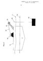
[0003] На фиг. 1 и 2 проиллюстрированы примеры проблемы, которую призваны решать системы компенсации вертикальной качки. Надводное судно 1, имеющее палубу 10, плавает над водной поверхностью, обозначенной ватерлинией 2. Палуба 10 возвышается над ватерлинией 2, и к ней прикреплено оборудование. Кран 40 или аналогичный подъемный механизм выполнен с возможностью вывешивания за борт полезного груза 60 и подъема или опускания груза 60 при помощи каната или троса 30, который на одном конце соединен с грузом 60, а на другом конце соединен с лебедкой 20. Трос 30 проходит по расположенному за бортом шкиву 50, при этом направление троса 30 изменяется от почти горизонтального до вертикального. В состоянии покоя сила натяжения в тросе 30 номинально равна сумме веса полезного груза 60 и веса троса 30 между шкивом 50 и грузом 60.[0003] FIG. Figures 1 and 2 illustrate examples of the problem that vertical roll compensation systems are designed to solve. A
[0004] На фиг. 2 судно 1 показано поднятым под действием волн выше условной линии 100, которая ранее находилась ниже, как показано на фиг. 1. Это происходит по истечении определенного периода времени, во время которого судно 1 и, в частности, забортный шкив 50 ускоряются в верхнем направлении. Судно 1 оказывает сопротивление данному ускорению, осаживаясь глубже в воду, как обозначено ватерлинией 2, расположенной ближе к палубе. Груз 60 тоже оказывает сопротивление данному ускорению вследствие комбинации силы тяжести, действующей на собственную массу груза, и силы сопротивления воды, действующей на груз 60 при его перемещении. В результате сила натяжения в тросе 30 увеличивается до тех пор, пока скорость вертикального перемещения груза 60 не станет равна скорости перемещения шкива 50 или не превысит ее. Повышенная сила натяжения в тросе 30 может достигать предельных значений и оказывает нагрузку на все компоненты системы, в том числе палубу 10, лебедку 20, кран 40, шкив 50, а также груз 60. Система в целом должна быть разработана с обеспечением противостояния действующим на нее усилиям при конкретном состоянии моря, определяющем безопасный рабочий диапазон. В противном случае тот или иной компонент системы выйдет из строя, ставя под угрозу выполнение поставленной задачи и подвергая опасности оборудование, персонал и/или полезный груз.[0004] FIG. 2,
[0005] Когда перемещение судна 1 вверх замедляется, в результате чего судно начинает возвращаться или оседать к своему исходному положению, все действующие усилия и напряжения уменьшаются, однако угроза механического повреждения не исчезает, а остается до тех пор, пока перемещение не будет остановлено. Те же силы сопротивления, которые действовали на груз 60 совместно с силой тяжести, оказывая сопротивление его перемещению в направлении вверх, также действуют на груз 60, опускающийся с такой же скоростью, как при падении под действием одной только силы тяжести. Фактически, шкив 50 может опускаться быстрее, чем груз 60. Это может вызвать падение натяжения в тросе 30 до нуля и провисание на одном или более отрезках троса 30. В данных условиях груз 60 ускоряется в направлении вниз, чему препятствует только сила сопротивления его перемещению в воде, без всякого натяжения сверху, которое ранее удерживало его на тросе 30. Когда перемещение шкива 50 вниз закончится и впоследствии изменится на обратное, трос 30 натянется до состояния возникновения «пружинящей нагрузки». Пружинящие нагрузки могут легко превысить разрывное усилие троса 30 и/или номинальную рабочую нагрузку других компонентов системы. Разрыв троса 30 и/или повреждение других компонентов системы может привести к утрате груза 60, потере времени и денег, а также к травмам или летальному исходу.[0005] When the movement of the
[0006] Вертикальная качка может быть определена как вертикальное перемещение забортного шкива 50, вызванное воздействием волны на судно, при этом для минимизации вышеописанных явлений и, следовательно, увеличения безопасного рабочего диапазона судна и соответствующего оборудования при выполнении поставленной задачи, используются системы компенсации вертикальной качки.[0006] Vertical pitching can be defined as the vertical movement of the
[0007] На фиг. 3 изображен обычный пример пассивной системы компенсации вертикальной качки, которая работает только на пружинах. Данная система является пассивной, поскольку после введения в действие не требует дополнительной энергии, кроме энергии, поступающей в систему в результате перемещения судна и самих полезных грузов. Палуба 10, лебедка 20, забортный шкив 50 и полезный груз 60 аналогичны показанным на вышерассмотренных чертежах. Как и в предыдущем случае, шкив 50 поддерживается краном 40 (не показан). Два шкивных блока 70 и 80 отделены друг от друга пружиной 90. Блок 70 закреплен на месте и может быть назван «закрепленным шкивным блоком», тогда как блок 80 выполнен с возможностью перемещения и может быть назван «выдвижным шкивным блоком». При необходимости выдвижной блок 80 перемещается в вертикальном направлении внутри опорной конструкции (не показана), которая надежно удерживает его по центру над блоком 70. Как показано на чертеже, пружина 90 ориентирована по существу вертикально относительно блоков 70, 80, расположенных на одной линии друг над другом, однако конфигурации с горизонтальным расположением также являются возможными и распространенными. Трос 30, который на вышерассмотренных чертежах проходил от лебедки 20 непосредственно по шкиву 50, теперь, перед тем как пройти по шкиву 50, сначала проходит по всей траектории вокруг закрепленного шкива 70 и выдвижного шкива 80. На чертеже изображен один полный оборот вокруг обоих шкивов 70, 80, но часто применяются траектории с несколькими оборотами, обычно двумя (что дает передаточное отношение, равное 4), так что более короткие перемещения шкива 80 могут компенсировать увеличенные амплитуды колебаний при вертикальной качке за счет более тугой пружины. Возможны и другие конфигурации шкивов, очевидные специалистам в данной области техники.[0007] FIG. Figure 3 shows a typical example of a passive pitch compensation system that only works on springs. This system is passive, because after putting into operation it does not require additional energy, except for the energy entering the system as a result of the movement of the vessel and the payload itself.
[0008] На фиг. 3А проиллюстрирована реакция механизма, показанного на фиг. 2, в ответ на направленную вверх вертикальную качку. Направленная вверх вертикальная качка А увеличивает силу натяжения троса 30 и вызывает сжатие пружины, что приводит к уменьшению расстояния между шкивными блоками В и высвобождению некоторой части троса 30, проходящего вокруг шкивных блоков, как показано на чертеже. Во время направленной вниз вертикальной качки А, как показано на фиг. 3В, уменьшенное натяжение троса 30 обеспечивает возможность расширения пружины с увеличением расстояния между блоками В, что, в свою очередь, устраняет провисание троса 30, которое могло бы возникнуть в противном случае. Очевидно, что коэффициент жесткости пружины должен соответствовать нагрузке, которая образована суммой полезного груза 60 и веса троса 30 между шкивом 50 и грузом 60. Если не учитывать силу трения, описанная пассивная система почти аналогична пружине 70, вставленной в трос 30 между шкивом 50 и полезным грузом, как показано на фиг. 4.[0008] FIG. 3A illustrates the response of the mechanism shown in FIG. 2, in response to an upward vertical roll. The upward vertical pitching A increases the tension force of the
[0009] На практике модификация цилиндрических пружин с учетом массы перемещаемого груза является нецелесообразной. Вместо этого в описанных пассивных системах вертикального перемещения применяются «газовые пружины», типовые компоненты которых изображены на фиг. 5. Газовая пружина 200 содержит поршень 210, выполненный с возможностью свободного перемещения внутри корпуса 220 с нижним уплотнением 230. Поршень 210 содержит уплотнения 211, препятствующие прохождению газа между поршнем 210 и его корпусом 220. В нижней части корпуса 220 расположен трубопровод, обеспечивающий возможность свободного прохождения газа между поршневым узлом 239 и аккумулятором 240. Внутренний объем корпуса 220 под уплотнениями 211 совместно с внутренним объемом аккумулятора 240 образует резервуар высокого давления. Объем указанного резервуара дополнительно увеличен путем подсоединения ряда газовых баллонов 250. Обычно газ представляет собой азот или воздух, однако возможно использование и других газов. При продвижении поршня 210 в корпус 220 газ, находящийся под уплотнениями 211, вытесняется и, таким образом, равномерно сжимается внутри всех компонентов, образующих резервуар высокого давления. Опуская вполне понятные частности, касающиеся температуры и неидеальных газов, коэффициент жесткости системы регулируют путем изменения давления внутри заполненной газом части пружины 200 на основании закона Бойля-Мариотта, согласно которому произведение давления р и объема v является постоянной величиной. Полностью пневматическая пружина, изображенная на фиг. 5, представляет собой пассивную пружину вертикального перемещения, однако обычно по причинам, не имеющим отношения к данному обсуждению, применяется комбинированная пневмогидравлическая пружина, изображенная на фиг. 6. В таких пружинах корпус 220 поршня, как и основная часть аккумулятора 242 и соединяющий его с корпусом трубопровод 235, заполнен текучей средой 241, находящейся ниже уплотнений 211. Когда поршень 210 входит в корпус 220, вместо непосредственного сжатия газа он вытесняет гидравлическую текучую среду в нижнюю часть аккумулятора. Граница 243 раздела между газом и текучей средой расположена внутри аккумулятора 240. При повышении уровня текучей среды в аккумуляторе 240 указанная среда сжимает газ в верхней части аккумулятора 240 и остальной части резервуара высокого давления точно таким же образом, как это делает поршень в полностью пневматическом варианте, изображенном на фиг. 5.[0009] In practice, the modification of coil springs, taking into account the mass of the transported load, is impractical. Instead, the described passive vertical movement systems employ “gas springs”, typical components of which are shown in FIG. 5. The
[0010] Коэффициент жесткости газовой пружины легко регулируется путем изменения давления в резервуаре высокого давления.[0010] The stiffness coefficient of the gas spring is easily adjusted by changing the pressure in the pressure vessel.
[0011] На фиг. 7 изображены основные компоненты газовой пружины, входящей в состав рассмотренной пассивной системы компенсации вертикальной качки. Система, изображенная и описанная выше, содержит один пневматический или гидравлический поршень, однако может иметься несколько поршней (часто два), расположенных между выдвижным шкивным блоком 80 и закрепленным шкивным блоком 70 и обычно питающих один аккумулятор 240.[0011] FIG. 7 shows the main components of a gas spring, which is part of the considered passive vertical compensation system. The system depicted and described above contains one pneumatic or hydraulic piston, however, there may be several pistons (often two) located between the extendable pulley block 80 and the fixed
[0012] Пассивные системы компенсации вертикальной качки, работающие на газовых пружинах, являются широко распространенными, простыми и эффективными в защите троса 30 от предельных колебаний натяжения. Тем не менее, пружина реагирует только на изменения натяжения троса 30 у забортного шкива 50, и любое изменение этого натяжения вызывает вертикальное перемещение груза 60 в толще воды. Данное натяжение номинально равно сумме веса в воде груза 60 и веса в воде троса 30 между шкивом 50 и грузом 60. Данный суммарный вес может быть назван «активной нагрузкой» и по большей части не зависит от физических свойств груза 60, троса 30 и от силы земного притяжения. В отсутствие вертикальной качки нагрузка, оказываемая на шкив (WOS), для забортного шкива 50 номинально равна активной нагрузке. Однако WOS чувствительна к вертикальной качке вследствие инерции полезного груза и сил сопротивления, действующих на груз 60 и трос 30. Если WOS на шкиве 50 превышает активную нагрузку, груз 60 поднимается в толще воды. Если же WOS на шкиве 50 ниже активной нагрузки, груз 60 опускается в воде.[0012] Passive pitching systems operating on gas springs are widespread, simple, and effective in protecting
[0013] Кроме того, пружина может не срабатывать до тех пор, пока дифференциальное натяжение является достаточным для преодоления трения в компонентах системы, которое может быть существенным. Сильное трение возникает: а) между уплотнениями 211 и корпусом поршня, б) в шкивах, поворачивающихся на соответствующих валах, при этом трение повышается при увеличении активной нагрузки, и с) между выдвижным шкивным блоком и его опорной конструкцией (в случае ее применения, не показана), которая ограничивает перемещение указанного блока. В дополнению к трению, возникающему в механизмах, трос 30 чаще всего является относительно крупным проволочным канатом, синтетическим канатом или соединителем с защитным покрытием. Такие канаты и тросы с трудом поддаются изгибу по поверхности шкива, а после изгиба оказывают сопротивление обратной деформации. К этому следует прибавить инерцию всех массивных металлических подвижных частей, которые оказывают изначальное сопротивление приведению в движение, но являются особенно чувствительными к изменению направления. Наконец, запас энергии в пружине будет восстанавливаться при замедлении вертикальной качки или изменении ее направления на обратное. Передаточная функция является хорошо известным, частотно-зависимым свойством пружин и определяется как соотношение между выходной и входной амплитудами колебаний пружины.[0013] In addition, the spring may not work as long as the differential tension is sufficient to overcome friction in the components of the system, which may be significant. Strong friction occurs: a) between the
[0014] По всем вышеуказанным причинам пассивные системы на основе пружин не обеспечивают поддержания неподвижности груза 60 в толще воды.[0014] For all of the above reasons, the passive systems based on the springs do not maintain the immobility of the
[0015] Когда остаточное перемещение груза 60 является чрезмерным для конкретно поставленной задачи, необходимо применять активную компенсацию вертикальной качки. Активные системы обеспечивают непосредственный контроль ослабления и натягивания троса 30, проходящего по забортному шкиву 50, и/или подъема шкива 50 для точной компенсации перемещения судна 1, что ограничено, главным образом, возможностью измерения и предсказания данного перемещения. Как правило, измерение и прогнозирование осуществляются датчиком перемещения (MRU), содержащим вычислительное устройство, средства программного обеспечения и устройства ввода данных, поступающих от различных сенсоров. Данные системы являются сложными и дорогостоящими, но, даже если они идеально обеспечивают измерение и прогнозирование перемещения, выполнение регулировок в режиме реального времени в этих физических системах (запуск, остановка лебедки 20 и изменение направления ее перемещения на обратное (фиг. 8) / подъем шкива / регулировки крана 40 (фиг. 9)) обычно требует значительного количества дополнительной энергии (гидравлической или электрической) и значительного усиления соответствующего оборудования, что дополнительно повышает затраты.[0015] When the residual movement of the
[0016] Существуют активные системы, в состав которых входят пассивные системы, описанные выше в данном документе. В этих случаях активная система создает дополнительную энергию (обычно гидравлическую) для усиления перемещения выдвижного шкивного блока 80. Такие системы называются активно-пассивными (АОР) системами и схематически изображены на фиг. 10 и 11. Систем, показанная на фиг. 10, отличается по схеме исполнения, но имеет те же функции, что и пассивные компенсационные системы с газовыми пружинами, рассмотренные выше. На фиг. 11 и 12 показано присоединение гидравлического активного усиливающего средства 300. Очевидно, почему указанные системы нуждаются лишь в небольшом количестве дополнительной энергии: пружина выполняет основную долю работы, подобно тому, как если бы работала только она пассивным образом. Единственным необходимым дополнительным усилием является усилие, требующееся для преодоления силы трения в системе, энергии, накопленной пружиной при ее поджатии из нейтрального заданного положения, и инерции подвижных частей.[0016] There are active systems that include passive systems described above in this document. In these cases, the active system creates additional energy (usually hydraulic) to enhance the movement of the retractable pulley block 80. Such systems are called active-passive (AOP) systems and are shown schematically in FIG. 10 and 11. The system shown in FIG. 10, differs in design, but has the same functions as passive compensation systems with gas springs, discussed above. In FIG. 11 and 12 show the connection of a hydraulic active reinforcing
[0017] На фиг. 13 изображена блок-схема описанной активно-пассивной системы. Мониторинг перемещения судна обеспечивается датчиком перемещения (MRU). Перемещение у забортного шкива и регулировки, необходимые для компенсации этого перемещения, рассчитываются с помощью вычислительного устройства или программируемого логического контроллера (PLC) на основании данных, предоставляемых MRU. Затем PLC направляет текучую среду для приведения в действие гидравлического цилиндра с перемещением в соответствующем направлении. Фактическое перемещение передается обратно к PLC от измерительного устройства. Активная часть системы, описанная выше, выполнена с гидравлическим цилиндром, однако специалистам должно быть понятно, что возможно использование других механизмов для добавления необходимой энергии, таких как двигатель, приводящий в действие реечную передачу.[0017] FIG. 13 is a block diagram of the described active-passive system. Vessel movement monitoring is provided by a motion sensor (MRU). Outboard pulley movement and adjustments necessary to compensate for this movement are calculated using a computing device or programmable logic controller (PLC) based on data provided by the MRU. The PLC then directs the fluid to drive the hydraulic cylinder with movement in the corresponding direction. Actual movement is transmitted back to the PLC from the measuring device. The active part of the system described above is made with a hydraulic cylinder, however, it should be clear to those skilled in the art that it is possible to use other mechanisms to add the necessary energy, such as an engine driving a rack and pinion gear.
На фиг. 14 проиллюстрирован другой недостаток, присущий системам компенсации с газовыми пружинами независимо от того, являются ли эти системы активными или пассивными. Подъемный трос, переносящий уравновешиваемый полезный груз, проходит по всем шкивам газовой пружины. Это справедливо не только при уравновешивании, но и при полном подъеме и опускании груза с судна на конечную рабочую глубину. На каждом шкиве трос или канат изгибается, проходя через указанный шкив, что приводит к износу. Данный документ касается «последовательной компенсации», а все последовательные компенсаторы представляют собой устройства, увеличивающие число перегибов по шкиву (BOS). Подъемный канат, будь то проволочный канат или современное синтетическое волокно, в условиях работы в море может иметь длину, например, в три или более мили, а его стоимость может превышать 150000 долларов. Таким образом, износ и повреждение каната являются серьезной проблемой даже без учета ценности груза, соединенного с судном с помощью только одной связи. Кроме того, в процессе обычных операций трудно контролировать состояние каната по всей его длине.In FIG. 14 illustrates another drawback inherent in gas spring compensation systems whether these systems are active or passive. A lifting cable carrying a balanced payload runs through all the gas spring pulleys. This is true not only when balancing, but also when the load is completely raised and lowered from the vessel to the final working depth. On each pulley, the cable or rope bends, passing through the specified pulley, which leads to wear. This document deals with “sequential compensation,” and all sequential compensators are devices that increase the number of kinks on the pulley (BOS). A hoisting rope, whether it be a wire rope or a modern synthetic fiber, in conditions of work at sea can have a length of, for example, three or more miles, and its cost can exceed 150,000 dollars. Thus, rope wear and damage is a serious problem even without taking into account the value of the cargo connected to the vessel using only one connection. In addition, during normal operations, it is difficult to control the condition of the rope along its entire length.
Ввиду всех вышеуказанных причин существует необходимость в создании маломощного устройства контроля полезного груза и систем компенсации вертикальной качки (активных или пассивных), а также соответствующих способов, в которых не требуется прохождение грузового каната, для которого выполняется компенсация вертикальной качки, по шкивам газовой пружины, выполняющей основную часть работы.For all the above reasons, there is a need to create a low-power device for controlling payload and pitching compensation systems (active or passive), as well as appropriate methods that do not require the passage of a freight rope, for which pitching compensation is performed, along gas spring pulleys that perform the bulk of the work.
СУЩНОСТЬ ИЗОБРЕТЕНИЯSUMMARY OF THE INVENTION
Один вариант выполнения изобретения относится к устройству контроля полезного груза, которое содержит поперечный канатный узел, содержащий приводной механизм поперечного каната, выдвижной шкивной узел поперечного каната, содержащий по меньшей мере один выдвижной шкив, по которому может проходить грузовой канат, и поперечный канат, один конец которого соединен с указанным приводным механизмом, а другой конец соединен с указанным выдвижным шкивным узлом, причем выдвижной шкивной узел может быть расположен с возможностью перемещения при помощи указанного приводного механизма поперечного каната в по меньшей мере одно положение так, что выдвижной шкив либо не соприкасается с частью грузового каната и отстоит от нее, либо соприкасается с указанной частью каната без изменения ее траектории, причем в непосредственной близости от выдвижного шкива указанная часть каната имеет прямолинейный отрезок длиной L1, при этом грузовой канат на одном своем участке соединен с лебедочным узлом, а на другом участке соединен с грузом, поднимаемым, опускаемым, позиционируемым или поддерживаемым в неизменном положении управляемым образом, и, кроме того, выдвижной шкивной узел может быть расположен с возможностью перемещения при помощи указанного приводного механизма по меньшей мере в другое положение так, что выдвижной шкив входит в соединительный контакт с указанной частью грузового каната вблизи выдвижного шкива с обеспечением изменения длины L1 прямолинейного отрезка грузового каната таким образом, что измененный отрезок каната не является прямолинейным и имеет длину L2, которая превышает длину L1. Следует понимать, что длина грузового каната между лебедкой и грузом не изменяется под действием перемещения судна, вызванного вертикальной качкой, а вместо этого согласно изобретению траектория грузового каната между лебедкой и грузом изменяется вследствие перемещения выдвижного шкива. Таким образом, в качестве иллюстрации можно сказать, что, когда судно оседает в ситуации вертикальной качки, что в ином случае вызвало бы и оседание груза, действие выдвижного шкива обеспечивает увеличение длины отрезка грузового каната, расположенного рядом с выдвижным шкивом, по которому проходит указанный канат, с уменьшением тем самым длины отрезка, расположенного после выдвижного шкива и, следовательно, предотвращением оседания груза. Согласно различным неограничивающим аспектам устройство контроля полезного груза может дополнительно иметь следующие особенности или дополнительно отличаться следующими ограничениями:One embodiment of the invention relates to a payload control device that comprises a transverse cable assembly comprising a transverse rope drive mechanism, a sliding pulley assembly of a transverse cable comprising at least one extendable pulley through which a cargo cable can pass, and a transverse cable, one end which is connected to the specified drive mechanism, and the other end is connected to the specified retractable pulley unit, and the retractable pulley unit can be arranged to move directly using the specified drive mechanism of the transverse rope in at least one position so that the retractable pulley either does not come in contact with a part of the cargo rope and is separated from it, or is in contact with the specified part of the rope without changing its path, and in the immediate vicinity of the retractable pulley, this part of the rope a line segment length L 1, the hoist rope at its one portion connected to the winch assembly, and the other portion is connected to the load, raise, lower, or positionable Bolster in an unchanged position in a controlled manner, and, in addition, the retractable pulley assembly can be positioned to move with the aid of said drive mechanism at least to another position so that the retractable pulley comes into contact with said part of the cargo cable in the vicinity of the retractable pulley with providing a change in the length L 1 of the straight segment of the cargo rope so that the changed segment of the rope is not straight and has a length L 2 that exceeds the length L 1 . It should be understood that the length of the cargo rope between the winch and the load does not change due to the movement of the vessel caused by vertical rolling, but instead, according to the invention, the path of the cargo rope between the winch and the load changes due to the movement of the retractable pulley. Thus, as an illustration, we can say that when the vessel settles in a vertical rolling situation, which otherwise would cause the subsidence of the cargo, the action of the retractable pulley provides an increase in the length of the length of the cargo rope located next to the retractable pulley along which the rope passes , thereby reducing the length of the segment located after the retractable pulley and, therefore, preventing the subsidence of the load. According to various non-limiting aspects, the payload monitoring device may additionally have the following features or additionally differ by the following restrictions:
- поперечный канат представляет собой жесткий материал,- the transverse rope is a rigid material,
- поперечный канат представляет собой гибкий материал,- the transverse rope is a flexible material,
- при этом поперечный канат представляет собой канат или трос,- wherein the transverse rope is a rope or cable,
- груз и по меньшей мере часть грузового каната расположены в толще воды,- the cargo and at least part of the cargo rope are located in the water column,
- устройство дополнительно содержит один или более вращаемых, закрепленных на месте шкивов, расположенных на траектории прохождения грузового каната в контакте или с возможностью контакта с ним, причем указанные один или более закрепленных шкивов обеспечивают стабилизацию траектории грузового каната, когда выдвижной шкив, входящий в состав поперечного канатного узла, находится в положении соединительного контакта с грузовым канатом, при котором происходит изменение его траектории,- the device further comprises one or more rotatable, fixed in place pulleys located on the trajectory of the freight rope in contact with or with the possibility of contact with him, moreover, these one or more fixed pulleys provide stabilization of the trajectory of the cargo rope when the retractable pulley included in the transverse cable node, is in the position of connecting contact with the cargo rope, in which there is a change in its trajectory,
- величина ΔL=L2-L1 является изменяемой управляемым образом,- the quantity ΔL = L2-L1 is variable in a controlled manner,
- поперечный канатный узел дополнительно содержит направляющую конструкцию выдвижного шкивного узла, задающую траекторию указанного узла, в пределах которой расположен с возможностью перемещения выдвижной шкив поперечного канатного узла, направляемый по указанной траектории,- the transverse rope unit further comprises a guide structure of the retractable pulley unit that defines the path of the specified node, within which is located the movable pulley of the transverse rope unit, which is guided along the specified path,
- причем устройство дополнительно содержит активный компенсатор, функционально соединенный с указанной направляющей конструкцией и шкивом поперечного канатного узла,- moreover, the device further comprises an active compensator, functionally connected to the specified guide structure and the pulley of the transverse rope unit,
- при этом активный компенсатор содержит компонент контроля отклика на перемещение и по меньшей мере один из следующих элементов: моторизованную реечную передачу, гидравлический цилиндр, пневматический цилиндр, третью приводную линию, тяговую лебедку или другой аналогичный элемент,- while the active compensator contains a component of the control response to movement and at least one of the following elements: a motorized rack and pinion gear, a hydraulic cylinder, a pneumatic cylinder, a third drive line, a traction winch or other similar element,
- приводной механизм поперечного каната содержит пружину и по меньшей мере один вращаемый подвижный шкив, на который действует указанная пружина,- the drive mechanism of the transverse rope contains a spring and at least one rotatable movable pulley, which acts on the specified spring,
- причем пружина представляет собой пневматическую пружину,- wherein the spring is a pneumatic spring,
- пружина представляет собой гидропневматическую пружину,- the spring is a hydropneumatic spring,
- приводной механизм поперечного каната содержит пассивное устройство компенсации вертикальной качки, выполненное в любой форме,- the drive mechanism of the transverse rope contains a passive vertical compensation device, made in any form,
- один конец поперечного каната прикреплен к приводному механизму поперечного каната,- one end of the transverse rope is attached to the drive mechanism of the transverse rope,
- один конец поперечного каната прикреплен к указанному по меньшей мере одному подвижному шкиву приводного механизма поперечного каната.- one end of the transverse rope is attached to the specified at least one movable pulley of the drive mechanism of the transverse rope.
Один вариант выполнения изобретения относится к способу контроля полезного груза, который необходимо поднять, опустить, позиционировать или удерживать на месте в неустойчивой среде. Способ включает использование полезного груза, прикрепленного к грузовому канату, имеющему локально прямолинейный отрезок, и вышеописанного устройства контроля полезного груза и использование указанного устройства для стабилизации полезного груза в неустойчивой среде.One embodiment of the invention relates to a method for controlling a payload that needs to be raised, lowered, positioned or held in place in an unstable environment. The method includes the use of a payload attached to a freight rope having a locally straight segment, and the above-described payload control device, and using said device to stabilize the payload in an unstable environment.
Согласно одному аспекту указанная неустойчивая среда является водой.In one aspect, said unstable medium is water.
КРАТКОЕ ОПИСАНИЕ ЧЕРТЕЖЕЙBRIEF DESCRIPTION OF THE DRAWINGS
Фиг. 1-14 изображают схематические виды, иллюстрирующие технологию известного уровня техники и ее недостатки,FIG. 1-14 are schematic views illustrating prior art technology and its disadvantages,
фиг. 15 изображает вид, схематически показывающий устройство контроля полезного груза, находящееся в незадействованном состоянии, согласно варианту выполнения изобретения,FIG. 15 is a view schematically showing a payload monitoring device in an idle state according to an embodiment of the invention,
фиг. 16 изображает вид, схематически показывающий устройство контроля полезного груза, изображенное на фиг. 15, в задействованном состоянии согласно аспекту изобретения,FIG. 16 is a view schematically showing the payload monitoring device of FIG. 15, in the activated state according to an aspect of the invention,
фиг. 17 схематически изображает устройство контроля полезного груза, находящееся в задействованном состоянии, согласно иллюстративному варианту выполнения изобретения,FIG. 17 schematically depicts a payload monitoring device in an engaged state, according to an illustrative embodiment of the invention,
фиг. 18 схематически изображает локально прямолинейный неизмененный отрезок I1 длиной L1 и удлиненный отрезок k длиной L2, когда устройство находится в задействованном состоянии, согласно иллюстративному варианту выполнения изобретения,FIG. 18 schematically depicts a locally rectilinear unaltered segment I 1 of length L 1 and an elongated segment k of length L 2 when the device is in the engaged state, according to an illustrative embodiment of the invention,
фиг. 19 изображает часть выдвижного шкивного узла устройства контроля полезного груза, изображенного на фиг. 17, в незадействованном состоянии,FIG. 19 depicts a portion of a retractable pulley assembly of the payload monitoring device of FIG. 17, in an idle state,
фиг. 20 изображает часть выдвижного шкивного узла устройства контроля полезного груза, изображенного на фиг. 19, в задействованном состоянии,FIG. 20 depicts a portion of a retractable pulley assembly of the payload monitoring device of FIG. 19, in the engaged state,
фиг. 21 изображает активный компенсационный компонент выдвижного шкивного узла согласно аспекту изобретения, иFIG. 21 shows an active compensation component of a retractable pulley assembly according to an aspect of the invention, and
фиг. 22, 23, 24 и 25 соответственно изображают схемы блоков и оснастки, показывающие различные передаточные отношения, которые могут использоваться при реализации изобретения.FIG. 22, 23, 24, and 25, respectively, depict block diagrams and accessories showing various gear ratios that may be used in the practice of the invention.
ПОДРОБНОЕ ОПИСАНИЕ НЕОГРАНИЧИВАЮЩИХ ТИПИЧНЫХ ВАРИАНТОВ ВЫПОЛНЕНИЯ ИЗОБРЕТЕНИЯDETAILED DESCRIPTION OF NON-LIMITING TYPICAL MODES FOR CARRYING OUT THE INVENTION
На фиг. 15 изображен вариант выполнения устройства 1000 контроля полезного груза. В представленном аспекте устройство находится в незадействованном состоянии. Хотя на чертеже показаны лебедка 1020, груз 1060 и верхняя и главная палубы морского судна, указанные элементы по существу не являются частью изобретения, а способствуют пояснению его работы.In FIG. 15 shows an embodiment of a
Устройство 1000 содержит поперечный канатный узел 1002, который содержит приводной механизм 1005 поперечного каната, выдвижной шкивной узел 1006, содержащий по меньшей мере один выдвижной шкив 1006-1, по которому может проходить грузовой канат 1030, и поперечный канат 1004, второй конец 1004-2 которого соединен с приводным механизмом поперечного каната, а первый конец 1004-1 соединен с выдвижным шкивным узлом 1006. Узел 1006 может быть расположен с возможностью перемещения при помощи приводного механизма поперечного каната в по меньшей мере одно положение так, что выдвижной шкив 1006-1 либо не соприкасается с частью грузового каната 1030 и отстоит от нее (см. фиг. 15), либо соприкасается с частью прямолинейного отрезка длиной L1 грузового каната без изменения его траектории (фиг. 18 и 19), при этом второй конец грузового каната соединен с лебедочным узлом 1020, а другая его часть (первый конец) соединен с грузом 1060, поднимаемым, опускаемым, позиционируемым или поддерживаемым в неподвижном положении управляемым образом. Кроме того, узел 1006 может быть расположен с возможностью перемещения при помощи указанного приводного механизма в по меньшей мере другое положение так, что шкив 1006-1 находится в положении соединительного контакта (см. фиг. 16) с частью прямолинейного отрезка грузового каната с изменением его траектории (см. также фиг. 18 и 20) таким образом, что указанный отрезок каната не является прямолинейным и имеет локальную длину L2, превышающую длину L1. Следует понимать, что длина грузового каната между лебедкой и грузом не изменяется под действием перемещения судна, вызванного вертикальной качкой, а вместо этого согласно изобретению траектория грузового каната между лебедкой и грузом изменяется вследствие перемещения выдвижного шкива. На фиг. 16 проиллюстрирована ситуация вертикальной качки, когда судно оседает на расстояние D, а положение груза отрегулировано на равную величину ΔL=L2-L1, в результате чего груз 1060 удерживается неподвижно в толще воды.The
На фиг. 17-21 подробно показаны конкретные аспекты типичного варианта выполнения изобретения. Согласно фиг. 17 и 21 поперечный канатный узел 1002 содержит приводной механизм 1005 поперечного каната, выполненный в виде газовой пружины 1008 и содержащий закрепленные и подвижные шкивы, разделенные пружиной 1008 (пневматической, гидропневматической и т.п.). На чертежах также показан направляющий элемент 1070 выдвижного шкивного узла, причем узел 1006 (и соединенный с ним шкив 1006-1) может перемещаться управляемым образом внутри указанного элемента в линейном направлении. Согласно фиг. 19 закрепленные шкивы 1090 могут (но необязательно должны) находиться в функциональном контакте с грузовым канатом 1030, когда устройство находится в незадействованном состоянии и не изменяет траекторию каната.In FIG. 17-21 show in detail specific aspects of a typical embodiment of the invention. According to FIG. 17 and 21, the
Следует понимать, что, хотя в вышеприведенном описании варианта выполнения изобретения поперечный канат имеет вид троса или веревочного каната, то есть выполнен из гибкого материала, канат 1004, изображенный на фиг. 15 и 16, может содержать жесткий, негибкий материал, например, в виде стержня, прутка или шеста, который может использоваться для перемещения выдвижного шкива между положением изменения траектории грузового каната и положением без изменения траектории. По существу, вариант выполнения устройства контроля полезного груза не обязательно содержит приводной механизм поперечного каната, содержащий газовую пружину или эквивалентный компонент, достаточно наличия выдвижного шкива, расположенного с возможностью перемещения при помощи приводного оборудования.It should be understood that, although in the above description of an embodiment of the invention, the transverse rope has the form of a rope or rope rope, that is, is made of flexible material, the
Кроме того, как показано на фиг. 21, выдвижной шкивной узел может содержать узел 1080 активного компенсатора, функционально соединенный с направляющей конструкцией и выдвижным шкивным узлом поперечного каната. Активный компенсатор содержит компонент контроля отклика на перемещение, входящий в состав датчиков и вычислительных устройств (не показаны) и обеспечивающий управление узлом 1080 механизированной реечной передачи. Кроме того или как вариант, активный компенсатор может содержать гидравлический цилиндр, пневматический цилиндр или третью приводную линию (не показана) для содействия перемещению выдвижного шкива.Furthermore, as shown in FIG. 21, the retractable pulley assembly may comprise an
Преимущественно, приводные механизмы 1005 поперечного каната (например, газовая пружина 1008) могут быть ориентированы на судне в любом положении так, как это необходимо или удобно. Кроме того, номинальная длина поперечного каната может составлять менее 200 футов (61 м), поскольку для компенсации больших амплитуд вертикальной качки в нестабильной среде достаточно, чтобы длина каната обеспечивала его прохождение от выдвижного шкивного узла 1006 и вокруг приводных механизмов. По существу, поперечный канат может быть легко проверен и заменен в случае необходимости и произвольно упрочнен. Наибольшим преимуществом является отсутствие необходимости использования относительно длинного, тяжелого, дорогостоящего и громоздкого грузового каната, проходящего по шкивам газовой пружины 1008, выполняющей основную часть работы по компенсации качки.Advantageously, transverse rope drive mechanisms 1005 (e.g., gas spring 1008) can be oriented on the vessel in any position as necessary or convenient. In addition, the nominal length of the transverse rope can be less than 200 feet (61 m), since to compensate for the large amplitudes of the vertical heave in an unstable environment, it is sufficient that the length of the rope allows it to extend from the sliding
Как показано на фиг. 22-25 и как должно быть понятно специалистам в данной области техники, приводной механизм поперечного каната (например, газовой пружины) может быть выполнен с передаточным отношением Nx, соответственно N=3, 4, 5, 6, при этом установка компонентов, содержащих дополнительные вспомогательные закрепленные шкивы 1090, практически не ограничена.As shown in FIG. 22-25 and as it should be clear to specialists in this field of technology, the drive mechanism of the transverse rope (for example, a gas spring) can be made with a gear ratio Nx, respectively N = 3, 4, 5, 6, while installing components containing additional auxiliary
Несмотря на то что в данном документе описаны и изображены несколько вариантов выполнения изобретения, специалистами в данной области техники легко может быть создан ряд других средств и/или конструкций для выполнения функции и/или достижения результатов и/или одного или более преимуществ, описанных в данном документе, при том предполагается, что каждое из таких изменений и/или модификаций находится в рамках объема описанных вариантов выполнения изобретения. В целом, специалистам должно быть очевидно, что все описанные в данном документе параметры, размеры, материалы и конфигурации приведены в качестве примера и что фактические параметры, размеры, материалы и/или конфигурации зависят от конкретной области или областей применения, в которых используется (используются) принцип(ы) данного изобретения. Специалистами могут быть выявлены или получены в ходе обычных экспериментов многочисленные аналоги конкретных вариантов выполнения изобретения, описанных в данном документе. Таким образом, следует понимать, что вышерассмотренные варианты выполнения приведены исключительно в качестве примера и что указанные варианты выполнения могут быть реализованы на практике иначе, чем описано и заявлено, без выхода при этом за рамки объема пунктов прилагаемой формулы изобретения и их эквивалентов. Варианты выполнения данного изобретения относятся к каждой конкретной особенности, системе, объекту, материалу, комплекту и/или способу, описанных в данном документе. Кроме того, любая комбинация двух или более таких особенностей, систем, объектов, материалов, комплектов и/или способов, если только они не являются взаимоисключающими, находится в рамках объема данного изобретения.Despite the fact that several embodiments of the invention are described and depicted in this document, a number of other tools and / or constructions can easily be created by those skilled in the art to perform a function and / or achieve results and / or one or more of the advantages described in this document, it being assumed that each of such changes and / or modifications is within the scope of the described embodiments of the invention. In general, it should be apparent to those skilled in the art that all of the parameters, sizes, materials and configurations described herein are given as an example and that the actual parameters, sizes, materials and / or configurations depend on the particular area or applications in which they are used (used ) principle (s) of the present invention. Numerous analogues of the specific embodiments of the invention described herein can be identified or obtained by those skilled in the art by those skilled in the art. Thus, it should be understood that the above embodiments are provided solely as an example, and that these embodiments can be implemented in practice otherwise than described and claimed, without going beyond the scope of the attached claims and their equivalents. Embodiments of the present invention relate to each specific feature, system, object, material, kit, and / or method described herein. In addition, any combination of two or more of these features, systems, objects, materials, kits and / or methods, unless they are mutually exclusive, is within the scope of this invention.
Следует понимать, что все определения, приведенные и используемые в данном документе, уточняют словарные определения, определения в документах, включенных в данный документ посредством ссылки, и/или обычные значения определяющих терминов.It should be understood that all definitions given and used in this document specify vocabulary definitions, definitions in documents included in this document by reference, and / or the usual meanings of the defining terms.
Используемые в описании и формуле изобретения данного документа формы единственного числа следует понимать как «по меньшей мере один», если четко не указано иное.Used in the description and claims of the present document, the singular should be understood as "at least one", unless clearly indicated otherwise.
Используемое в описании и формуле изобретения данного документа выражение «и/или» следует понимать как «любой или оба» из объединенных данным выражением элементов, то есть элементов, которые в некоторых случаях присутствуют совместно, а в других случаях - по отдельности. Перечисление нескольких элементов с использованием выражения «и/или» следует толковать точно таким же образом, то есть как «один или более» элементов, объединенных данным выражением. Возможно наличие и других элементов, отличных от элементов, конкретно указанных под условием «и/или», независимо от того, относятся эти другие элементы к конкретно указанным или нет. Так, в качестве неограничивающего примера, выражение «А и/или В», используемое с неограничивающими формулировками, такими как «содержащий», может относиться в одном варианте выполнения только к А (и при необходимости также к элементам, отличным от В), в другом варианте выполнения только к В (и при необходимости также к элементам, отличным от А), в еще одном варианте выполнения как к А, так и к В (и при необходимости также к другим элементам) и т.д.The expression “and / or” used in the description and claims of this document should be understood as “either or both” of the elements combined by this expression, that is, elements that are present together in some cases, and in other cases separately. Enumeration of several elements using the expression "and / or" should be interpreted in exactly the same way, that is, as "one or more" elements combined by this expression. There may be other elements other than the elements specifically indicated under the condition "and / or", regardless of whether these other elements are specifically specified or not. So, as a non-limiting example, the expression “A and / or B”, used with non-limiting formulations, such as “comprising”, may refer in one embodiment only to A (and, if necessary, also to elements other than B), in in another embodiment, only to B (and, if necessary, also to elements other than A), in yet another embodiment, to both A and B (and, if necessary, also to other elements), etc.
Используемый в описании и формуле изобретения данного документа союз «или» следует понимать в таком же значении, что и выражение «и/или», как изложено выше. Например, при перечислении отдельных элементов выражения «или» либо «и/или» следует интерпретировать как включающие, то есть охватывающие по меньшей мере один, но также и более одного из ряда перечисляемых элементов, а также, при необходимости, дополнительные, не перечисленные предметы. Только выражения, четко указывающие на обратное, такие как «только один из» или «ровно один из», либо используемое в формуле изобретения выражение «состоящий из» подразумевают включение ровно одного элемента из нескольких элементов или перечня элементов. В целом, используемое в данном документе выражение «или» следует интерпретировать только как указание на исключающие варианты (то есть «один или другой, но не оба»), если ему предшествовали выражения, указывающие на исключение, такие как «любой», «один из», «только один из» или «ровно один из». Выражение «состоящий по существу из», используемое в формуле изобретения, имеет значение, обычно присущее ему при использовании в области патентного права.Used in the description and claims of this document, the union “or” should be understood in the same meaning as the expression “and / or”, as described above. For example, when enumerating individual elements, the expressions “or” or “and / or” should be interpreted as including, that is, covering at least one, but also more than one of a number of enumerated elements, as well as, if necessary, additional, not listed items . Only expressions clearly indicating the opposite, such as “only one of” or “exactly one of”, or the expression “consisting of” used in the claims, mean including exactly one element from several elements or a list of elements. In general, the expression “or” used in this document should only be interpreted as indicating exclusionary options (that is, “one or the other, but not both”) if it was preceded by expressions indicating an exception, such as “any”, “one of "," only one of "or" exactly one of. " The expression “consisting essentially of”, as used in the claims, has the meaning usually inherent in it when used in the field of patent law.
Используемое в описании и формуле изобретения данного документа выражение «по меньшей мере один», относящееся к перечню из одного или более элементов, следует понимать как обозначающее по меньшей мере один элемент, выбранный из любого одного или более элементов в данном перечне, но не обязательно включающее по меньшей мере все до единого элементы, конкретно указанные в перечне, а также не исключающее любые комбинации элементов в указанном перечне. Кроме того, данное определение также предполагает возможность наличия при необходимости других элементов, отличных от конкретно перечисленных элементов, к которым относится выражение «по меньшей мере один», независимо от того, относятся эти другие элементы к конкретно указанным или нет. Так, в качестве неограничивающего примера, выражение «по меньшей мере один из А и В» (или, что то же самое, «по меньшей мере один из А или В» или, что то же самое, «по меньшей мере один из А и/или В») может относиться в одном варианте выполнения к по меньшей мере одному А, при необходимости охватывая более одного А, при этом В отсутствует (и при необходимости охватывая элементы, отличные от В), в другом варианте выполнения - к по меньшей мере одному В, при необходимости охватывая более одного В, при этом А отсутствует (и при необходимости охватывая элементы, отличные от А), в еще одном варианте выполнения - к по меньшей мере одному А, при необходимости охватывая более одного А, и по меньшей мере одному В, при необходимости охватывая более одного В (и при необходимости охватывая другие элементы), и т.д.Used in the description and claims of the present document, the expression "at least one", referring to a list of one or more elements, should be understood as indicating at least one element selected from any one or more elements in this list, but not necessarily including at least every single element specifically specified in the list, and also not excluding any combination of elements in the specified list. In addition, this definition also implies the possibility of the presence, if necessary, of other elements other than the specifically listed elements, to which the expression "at least one" refers, regardless of whether these other elements are specifically specified or not. So, as a non-limiting example, the expression “at least one of A and B” (or, which is the same, “at least one of A or B” or, which is the same, “at least one of A and / or B ") may refer in one embodiment to at least one A, if necessary covering more than one A, while B is absent (and if necessary covering elements other than B), in another embodiment, to at least at least one B, if necessary covering more than one B, while A is absent (and, if necessary, covering elements other than A), in yet another embodiment, to at least one A, optionally spanning more than one A, and at least one B, optionally spanning more than one B (and optionally spanning other elements), and etc.
Кроме того, следует понимать, что, если четко не указано иное, в любом из заявленных в данном документе способов, которые включают более одного этапа или действия, последовательность указанных этапов или действий способа не обязательно ограничена порядком, в котором они перечислены.In addition, it should be understood that, unless clearly indicated otherwise, in any of the methods claimed in this document, which include more than one step or action, the sequence of these steps or actions of the method is not necessarily limited to the order in which they are listed.
В формуле изобретения, так же как и в приведенном выше описании, все переходные фразы, такие как «содержащий», «включающий», «поддерживающий», «имеющий», «вмещающий», «охватывающий», «удерживающий», «состоящий из» и т.п., следует понимать как допускающие широкое толкование, то есть подразумевающие включение, но не ограничение. Только такие выражения, как «состоящий из» и «состоящий по существу из» являются соответственно ограничивающими или по существу ограничивающими, как изложено в Руководстве Патентного Ведомства США по Порядку Проведения Патентной Экспертизы, раздел 2111.03.In the claims, as well as in the above description, all transitional phrases, such as “comprising”, “including”, “supporting”, “having”, “containing”, “covering”, “holding”, “consisting of ”, Etc., should be understood as allowing a broad interpretation, that is, implying inclusion, but not limitation. Only expressions such as “consisting of” and “consisting essentially of” are respectively limiting or essentially limiting, as set forth in the Patent Office Guidelines for Patent Examination, section 2111.03.
Claims (29)
Applications Claiming Priority (3)
| Application Number | Priority Date | Filing Date | Title |
|---|---|---|---|
| US201261714792P | 2012-10-17 | 2012-10-17 | |
| US61/714,792 | 2012-10-17 | ||
| PCT/US2013/065225 WO2014062792A1 (en) | 2012-10-17 | 2013-10-16 | Payload control apparatus, method, and applications |
Publications (2)
| Publication Number | Publication Date |
|---|---|
| RU2015114168A RU2015114168A (en) | 2016-12-10 |
| RU2641390C2 true RU2641390C2 (en) | 2018-01-17 |
Family
ID=50488725
Family Applications (1)
| Application Number | Title | Priority Date | Filing Date |
|---|---|---|---|
| RU2015114168A RU2641390C2 (en) | 2012-10-17 | 2013-10-16 | Device, method and application versions for useful load control |
Country Status (10)
| Country | Link |
|---|---|
| US (1) | US9834417B2 (en) |
| EP (1) | EP2909128B1 (en) |
| CN (1) | CN104903227B (en) |
| AU (1) | AU2013331342B2 (en) |
| BR (1) | BR112015008677B1 (en) |
| CA (1) | CA2888446C (en) |
| MX (1) | MX356405B (en) |
| NZ (1) | NZ707032A (en) |
| RU (1) | RU2641390C2 (en) |
| WO (1) | WO2014062792A1 (en) |
Families Citing this family (13)
| Publication number | Priority date | Publication date | Assignee | Title |
|---|---|---|---|---|
| US20150129529A1 (en) * | 2013-11-13 | 2015-05-14 | Lee David Screaton | Marine lifting apparatus |
| US10246950B2 (en) * | 2015-02-05 | 2019-04-02 | Nabors Drilling Technologies Usa, Inc. | Deadline compensator |
| GB2538986A (en) * | 2015-06-02 | 2016-12-07 | Marine Electrical Consulting Ltd | Method and apparatus for adaptive motion compensation |
| US9630814B2 (en) * | 2015-07-14 | 2017-04-25 | Arthur Southerland, JR. | System and apparatus for motion compensation and anti-pendulation |
| DE102016005477A1 (en) * | 2016-05-03 | 2017-11-09 | Hycom B.V. | Compensation device for maintaining predetermined target positions of a manageable load |
| US10669137B2 (en) * | 2017-09-25 | 2020-06-02 | Wt Industries, Llc | Heave compensation system |
| US10042067B1 (en) * | 2017-09-25 | 2018-08-07 | The United States Of America As Represented By The Secretary Of The Navy | Safety system for a towed source |
| JP6565123B2 (en) * | 2017-11-10 | 2019-08-28 | ウラカミ合同会社 | Winch device with auto tension function |
| DE202018101068U1 (en) * | 2018-02-27 | 2019-06-06 | Zasche handling GmbH | Electric Balancing Hoist |
| CN108992080B (en) * | 2018-05-31 | 2022-05-10 | 东软医疗系统股份有限公司 | Gravity balance mechanism |
| EP3708528B1 (en) * | 2019-03-12 | 2021-10-13 | BAUER Maschinen GmbH | Working machine and method for operating same |
| NO346752B1 (en) * | 2019-07-04 | 2022-12-12 | Newtech As | A floating foundation for an offshore wind turbine, a system for extracting energy from wind, and a method of installing a wind turbine |
| CN112270865B (en) * | 2020-10-12 | 2021-08-27 | 浙江大学 | Big aircraft steering wheel analogue means based on spring module loading |
Citations (4)
| Publication number | Priority date | Publication date | Assignee | Title |
|---|---|---|---|---|
| US4285502A (en) * | 1977-06-01 | 1981-08-25 | Lub Dirk J C | Device for keeping constant the tensile stress in a cable |
| RU2171771C1 (en) * | 2000-10-04 | 2001-08-10 | Открытое акционерное общество "Ракетно-космическая корпорация "Энергия" им. С.П. Королева" | Regulator of tension of flexible member wound off drum |
| WO2012128637A1 (en) * | 2011-03-23 | 2012-09-27 | Flamek Ltd | A device for tightening rope |
| WO2012136350A1 (en) * | 2011-04-04 | 2012-10-11 | Rolls-Royce Marine As | Tensioning device |
Family Cites Families (35)
| Publication number | Priority date | Publication date | Assignee | Title |
|---|---|---|---|---|
| US943509A (en) * | 1908-04-20 | 1909-12-14 | Otto Adam | Electrical cableway system. |
| US1281323A (en) * | 1917-04-06 | 1918-10-15 | Bucyrus Co | Anchorage for excavator track-lines. |
| US1592828A (en) * | 1924-01-01 | 1926-07-20 | Gray Arthur Gerald | Derrick or crane |
| DE1107311B (en) | 1956-11-27 | 1961-05-25 | Telegraph Constr & Maintenance | Method and apparatus for regulating the movement of a submarine cable during laying out or retrieving |
| NL139703B (en) * | 1968-08-12 | 1973-09-17 | Ihc Holland Nv | DEVICE FOR TROUBLESHOOTING WATER, SUCH AS AT SEA, HANDLING A LOAD RELATING TO A PARTICULAR POINT. |
| US3653635A (en) * | 1969-11-17 | 1972-04-04 | Joe Stine Inc | Wave motion compensating apparatus for use with floating hoisting systems |
| CA961477A (en) * | 1971-03-02 | 1975-01-21 | Compagnie Francaise Des Petroles | Dispositif d'antipilonnement monte sur une embarcation pour le maintien d'un cable a un niveau donne au-dessus d'un fond subaquatique |
| US3785445A (en) | 1972-05-01 | 1974-01-15 | J Scozzafava | Combined riser tensioner and drill string heave compensator |
| US3894582A (en) * | 1972-06-08 | 1975-07-15 | Kammerer Jr Archer W | Slack removal apparatus |
| FR2344490A1 (en) | 1976-03-18 | 1977-10-14 | Elf Aquitaine | DEVICE FOR COMPENSATION OF VARIATIONS IN DISTANCE BETWEEN AN OBJECT FLOATING ON WATER AND THE BOTTOM OF IT |
| US4157812A (en) * | 1977-08-15 | 1979-06-12 | Bunker Ramo Corporation | Ship motion compensator for recovery of oceanographic instrumentation |
| GB2045196B (en) * | 1979-03-31 | 1982-12-08 | Ferranti Ltd | Cable tensioning device |
| US4522285A (en) * | 1983-10-20 | 1985-06-11 | Otis Elevator Company | Hydraulic tie-down for elevators |
| DE3546277A1 (en) * | 1985-12-28 | 1987-07-02 | Bomag Menck Gmbh | COMPENSATOR DEVICE |
| US5190107A (en) | 1991-04-23 | 1993-03-02 | Shell Oil Company | Heave compensated support system for positioning subsea work packages |
| US5894895A (en) | 1996-11-25 | 1999-04-20 | Welsh; Walter Thomas | Heave compensator for drill ships |
| US6082947A (en) * | 1999-08-17 | 2000-07-04 | Adamson; James E. | Coordinated motion marine lifting device |
| WO2001029366A1 (en) | 1999-10-19 | 2001-04-26 | Roodenburg, Joop | Hoisting mechanism, with compensator installed in a hoisting cable system |
| US6926103B1 (en) | 2001-07-02 | 2005-08-09 | Itrec B.V. | Splittable block on a derrick |
| US6926259B1 (en) | 2003-03-12 | 2005-08-09 | Itrec B.V. | Hoist system |
| JP2004332890A (en) | 2003-05-12 | 2004-11-25 | Mitsui Eng & Shipbuild Co Ltd | Hoisting device with vertical movement compensation function |
| US7231981B2 (en) | 2003-10-08 | 2007-06-19 | National Oilwell, L.P. | Inline compensator for a floating drill rig |
| US6935262B2 (en) * | 2004-01-28 | 2005-08-30 | Itrec B.V. | Method for lowering an object to an underwater installation site using an ROV |
| GB0406336D0 (en) | 2004-03-19 | 2004-04-21 | Subsea 7 Uk | Apparatus and method |
| CA2573126A1 (en) | 2004-07-01 | 2006-01-19 | Cudd Pressure Control, Inc. | Heave compensated snubbing system and method |
| US7191837B2 (en) | 2004-07-20 | 2007-03-20 | Coles Robert A | Motion compensator |
| ATE494257T1 (en) * | 2005-12-07 | 2011-01-15 | Ihc Holland Ie N V | METHOD FOR HANDLING LOADS IN SEA, AND SEA COMPENSATORS |
| WO2007145503A1 (en) * | 2006-06-16 | 2007-12-21 | Itrec B.V. | Heave motion compensation |
| US7798471B2 (en) | 2006-08-15 | 2010-09-21 | Hydralift Amclyde, Inc. | Direct acting single sheave active/passive heave compensator |
| US7389973B1 (en) * | 2007-02-15 | 2008-06-24 | Samson Rope Technologies | Tensioning systems and methods for line spooling |
| GB0705110D0 (en) * | 2007-03-16 | 2007-04-25 | Lewis Ltd | Wireline intervention system |
| US7934561B2 (en) | 2007-04-10 | 2011-05-03 | Intermoor, Inc. | Depth compensated subsea passive heave compensator |
| WO2009120062A2 (en) * | 2008-03-26 | 2009-10-01 | Itrec B.V. | Heave compensation system and method |
| EP2477927B1 (en) | 2009-09-18 | 2015-12-23 | Itrec B.V. | Hoisting device |
| EP2576331B1 (en) | 2010-06-02 | 2015-07-08 | Itrec B.V. | Marine load raising and lowering system |
-
2013
- 2013-10-16 CA CA2888446A patent/CA2888446C/en active Active
- 2013-10-16 US US14/436,105 patent/US9834417B2/en active Active
- 2013-10-16 NZ NZ707032A patent/NZ707032A/en not_active IP Right Cessation
- 2013-10-16 MX MX2015004860A patent/MX356405B/en active IP Right Grant
- 2013-10-16 CN CN201380062338.3A patent/CN104903227B/en active Active
- 2013-10-16 BR BR112015008677-2A patent/BR112015008677B1/en active IP Right Grant
- 2013-10-16 WO PCT/US2013/065225 patent/WO2014062792A1/en active Application Filing
- 2013-10-16 RU RU2015114168A patent/RU2641390C2/en active
- 2013-10-16 AU AU2013331342A patent/AU2013331342B2/en active Active
- 2013-10-16 EP EP13847441.6A patent/EP2909128B1/en active Active
Patent Citations (4)
| Publication number | Priority date | Publication date | Assignee | Title |
|---|---|---|---|---|
| US4285502A (en) * | 1977-06-01 | 1981-08-25 | Lub Dirk J C | Device for keeping constant the tensile stress in a cable |
| RU2171771C1 (en) * | 2000-10-04 | 2001-08-10 | Открытое акционерное общество "Ракетно-космическая корпорация "Энергия" им. С.П. Королева" | Regulator of tension of flexible member wound off drum |
| WO2012128637A1 (en) * | 2011-03-23 | 2012-09-27 | Flamek Ltd | A device for tightening rope |
| WO2012136350A1 (en) * | 2011-04-04 | 2012-10-11 | Rolls-Royce Marine As | Tensioning device |
Also Published As
| Publication number | Publication date |
|---|---|
| NZ707032A (en) | 2017-01-27 |
| BR112015008677A2 (en) | 2017-07-04 |
| WO2014062792A1 (en) | 2014-04-24 |
| EP2909128A1 (en) | 2015-08-26 |
| CN104903227B (en) | 2018-01-26 |
| CA2888446C (en) | 2020-10-27 |
| EP2909128A4 (en) | 2016-06-15 |
| EP2909128B1 (en) | 2019-07-31 |
| MX356405B (en) | 2018-05-25 |
| BR112015008677B1 (en) | 2021-07-27 |
| AU2013331342B2 (en) | 2016-11-10 |
| US20150266704A1 (en) | 2015-09-24 |
| CN104903227A (en) | 2015-09-09 |
| MX2015004860A (en) | 2016-01-12 |
| RU2015114168A (en) | 2016-12-10 |
| CA2888446A1 (en) | 2014-04-24 |
| AU2013331342A1 (en) | 2015-05-07 |
| US9834417B2 (en) | 2017-12-05 |
Similar Documents
| Publication | Publication Date | Title |
|---|---|---|
| RU2641390C2 (en) | Device, method and application versions for useful load control | |
| CN109195900B (en) | Movable in-line heave compensator | |
| US10843904B2 (en) | Offshore crane heave compensation control system and method using visual ranging | |
| US8949058B2 (en) | System for determining the load mass of a load carried by a hoist cable of a crane | |
| KR101285980B1 (en) | Crane control for the control of a hoisting gear of a crane | |
| US20090232625A1 (en) | Motion compensation system | |
| EP2896589A1 (en) | Method and apparatus | |
| CN211056582U (en) | Passive compensation winch system of scientific investigation ship | |
| CN109231050B (en) | Cable slack compensation device of scientific investigation ship winch system and application method thereof | |
| US4593885A (en) | Portable balanced motion compensated lift apparatus | |
| US4215851A (en) | System for active compensation of unwanted relative movements, preferably during loading of cargo | |
| CN103979416B (en) | Crane ship A support compensation of undulation actuating unit | |
| CN110790167A (en) | Scientific investigation ship passive compensation winch system and use method thereof | |
| Huster et al. | Design and operational performance of a standalone passive heave compensation system for a work class ROV | |
| CN109703696A (en) | Passive type wave compensating device for ROV folding and unfolding | |
| CN103149959A (en) | Digital electric hydraulic control system for retraction and release of offshore spill oil recovery treatment device | |
| NO342595B1 (en) | Rotary inline heave compensator | |
| NL1037953C2 (en) | Heave compensated chute. | |
| Herdzik | Utilization of an active and/or passive heave compensation in the equipment of dynamic positioning vessels | |
| GB2045196A (en) | Cable tensioning device | |
| US20230382692A1 (en) | Heave compensator enabling active heave counteraction | |
| NO20161987A1 (en) | Horizontal wireline compensator | |
| RU157045U1 (en) | WINCH FOR LIFTING FLOATING GOODS | |
| Meskers et al. | A damping tugger system for offshore heavy lifts | |
| Andreassen | Installation of subsea equipment in ultra-deep water using fibre rope deployment system |