RU2639366C2 - Rail vehicle - Google Patents
Rail vehicle Download PDFInfo
- Publication number
- RU2639366C2 RU2639366C2 RU2014149144A RU2014149144A RU2639366C2 RU 2639366 C2 RU2639366 C2 RU 2639366C2 RU 2014149144 A RU2014149144 A RU 2014149144A RU 2014149144 A RU2014149144 A RU 2014149144A RU 2639366 C2 RU2639366 C2 RU 2639366C2
- Authority
- RU
- Russia
- Prior art keywords
- cars
- rod
- car
- rotation
- rail vehicle
- Prior art date
Links
- 230000007246 mechanism Effects 0.000 abstract description 10
- 230000000694 effects Effects 0.000 abstract 1
- 230000000284 resting effect Effects 0.000 abstract 1
- 239000000126 substance Substances 0.000 abstract 1
- 230000001133 acceleration Effects 0.000 description 3
- 238000012423 maintenance Methods 0.000 description 2
- 238000004519 manufacturing process Methods 0.000 description 2
- 206010012411 Derailment Diseases 0.000 description 1
- 230000001419 dependent effect Effects 0.000 description 1
- 238000009434 installation Methods 0.000 description 1
- 230000004048 modification Effects 0.000 description 1
- 238000012986 modification Methods 0.000 description 1
- 230000009467 reduction Effects 0.000 description 1
- 238000007789 sealing Methods 0.000 description 1
- 230000007704 transition Effects 0.000 description 1
Images
Classifications
-
- B—PERFORMING OPERATIONS; TRANSPORTING
- B61—RAILWAYS
- B61D—BODY DETAILS OR KINDS OF RAILWAY VEHICLES
- B61D3/00—Wagons or vans
- B61D3/02—Wagons or vans with multiple deck arrangements
-
- B—PERFORMING OPERATIONS; TRANSPORTING
- B61—RAILWAYS
- B61F—RAIL VEHICLE SUSPENSIONS, e.g. UNDERFRAMES, BOGIES OR ARRANGEMENTS OF WHEEL AXLES; RAIL VEHICLES FOR USE ON TRACKS OF DIFFERENT WIDTH; PREVENTING DERAILING OF RAIL VEHICLES; WHEEL GUARDS, OBSTRUCTION REMOVERS OR THE LIKE FOR RAIL VEHICLES
- B61F3/00—Types of bogies
- B61F3/02—Types of bogies with more than one axle
-
- B—PERFORMING OPERATIONS; TRANSPORTING
- B61—RAILWAYS
- B61D—BODY DETAILS OR KINDS OF RAILWAY VEHICLES
- B61D3/00—Wagons or vans
- B61D3/10—Articulated vehicles
-
- B—PERFORMING OPERATIONS; TRANSPORTING
- B61—RAILWAYS
- B61D—BODY DETAILS OR KINDS OF RAILWAY VEHICLES
- B61D13/00—Tramway vehicles
-
- B—PERFORMING OPERATIONS; TRANSPORTING
- B61—RAILWAYS
- B61D—BODY DETAILS OR KINDS OF RAILWAY VEHICLES
- B61D17/00—Construction details of vehicle bodies
- B61D17/04—Construction details of vehicle bodies with bodies of metal; with composite, e.g. metal and wood body structures
- B61D17/20—Communication passages between coaches; Adaptation of coach ends therefor
-
- B—PERFORMING OPERATIONS; TRANSPORTING
- B61—RAILWAYS
- B61F—RAIL VEHICLE SUSPENSIONS, e.g. UNDERFRAMES, BOGIES OR ARRANGEMENTS OF WHEEL AXLES; RAIL VEHICLES FOR USE ON TRACKS OF DIFFERENT WIDTH; PREVENTING DERAILING OF RAIL VEHICLES; WHEEL GUARDS, OBSTRUCTION REMOVERS OR THE LIKE FOR RAIL VEHICLES
- B61F3/00—Types of bogies
- B61F3/12—Types of bogies specially modified for carrying adjacent vehicle bodies of articulated trains
-
- B—PERFORMING OPERATIONS; TRANSPORTING
- B61—RAILWAYS
- B61F—RAIL VEHICLE SUSPENSIONS, e.g. UNDERFRAMES, BOGIES OR ARRANGEMENTS OF WHEEL AXLES; RAIL VEHICLES FOR USE ON TRACKS OF DIFFERENT WIDTH; PREVENTING DERAILING OF RAIL VEHICLES; WHEEL GUARDS, OBSTRUCTION REMOVERS OR THE LIKE FOR RAIL VEHICLES
- B61F5/00—Constructional details of bogies; Connections between bogies and vehicle underframes; Arrangements or devices for adjusting or allowing self-adjustment of wheel axles or bogies when rounding curves
- B61F5/02—Arrangements permitting limited transverse relative movements between vehicle underframe or bolster and bogie; Connections between underframes and bogies
- B61F5/22—Guiding of the vehicle underframes with respect to the bogies
-
- B—PERFORMING OPERATIONS; TRANSPORTING
- B61—RAILWAYS
- B61G—COUPLINGS; DRAUGHT AND BUFFING APPLIANCES
- B61G5/00—Couplings for special purposes not otherwise provided for
- B61G5/02—Couplings for special purposes not otherwise provided for for coupling articulated trains, locomotives and tenders or the bogies of a vehicle; Coupling by means of a single coupling bar; Couplings preventing or limiting relative lateral movement of vehicles
-
- Y—GENERAL TAGGING OF NEW TECHNOLOGICAL DEVELOPMENTS; GENERAL TAGGING OF CROSS-SECTIONAL TECHNOLOGIES SPANNING OVER SEVERAL SECTIONS OF THE IPC; TECHNICAL SUBJECTS COVERED BY FORMER USPC CROSS-REFERENCE ART COLLECTIONS [XRACs] AND DIGESTS
- Y02—TECHNOLOGIES OR APPLICATIONS FOR MITIGATION OR ADAPTATION AGAINST CLIMATE CHANGE
- Y02T—CLIMATE CHANGE MITIGATION TECHNOLOGIES RELATED TO TRANSPORTATION
- Y02T30/00—Transportation of goods or passengers via railways, e.g. energy recovery or reducing air resistance
Landscapes
- Engineering & Computer Science (AREA)
- Mechanical Engineering (AREA)
- Transportation (AREA)
- Life Sciences & Earth Sciences (AREA)
- Wood Science & Technology (AREA)
- Platform Screen Doors And Railroad Systems (AREA)
- Handcart (AREA)
- Body Structure For Vehicles (AREA)
- Train Traffic Observation, Control, And Security (AREA)
Abstract
Description
Область техники, к которой относится изобретение FIELD OF THE INVENTION
[0001] Изобретение относится к рельсовому транспортному средству, в частности к низкопольному трамваю, содержащему соединительный вагон, установленный между двумя вагонами, поддерживающий эти вагоны и установленный с опорой на собственную тележку.[0001] The invention relates to a rail vehicle, in particular to a low-floor tram, comprising a connecting car mounted between two cars, supporting these cars and supported by its own carriage.
Уровень техникиState of the art
[0002] Известны технические решения для трамваев, в которых все вагоны, снабженные тележками, содержат жестко закрепленные тележки, установленные без возможности поворота относительно вагона или имеющие лишь небольшую гибкость в направлении поворота (далее "жестко закрепленная тележка"), что вызывает возникновение высоких боковых ускорений отдельных вагонов.[0002] Technical solutions are known for trams in which all wagons equipped with trolleys contain rigidly mounted trolleys mounted without being able to rotate relative to the wagon or having only slight flexibility in the direction of rotation (hereinafter referred to as “rigidly mounted trolley”), which causes the appearance of high lateral accelerations of individual wagons.
[0003] В некоторых трамваях центральная вагонная секция (соединительный вагон) содержит одну жестко закрепленную тележку, а каждый из вагонов, присоединенных к ней, содержит тележку, установленную с возможностью поворота вокруг одной оси поворота.[0003] In some trams, the central carriage section (connecting carriage) comprises one rigidly mounted carriage, and each of the carriages attached to it contains a carriage mounted to rotate about one pivot axis.
[0004] Используются также решения, в которых все тележки установлены с возможностью поворота вокруг одной оси поворота, при этом соединительный вагон снабжен двумя тележками, в то время как каждый из концевых вагонов содержит одну тележку. Недостатком такой конструкции является ограничение длины вагонов и большое количество тележек по отношению к длине поезда.[0004] Solutions are also used in which all the bogies are pivotally mounted about one pivot axis, the connecting car being provided with two trolleys, while each of the trailer cars contains one trolley. The disadvantage of this design is the limitation of the length of cars and a large number of bogies in relation to the length of the train.
[0005] Используется также конструкция, содержащая две тележки с двумя осями поворота, при этом последовательно соединенные вагоны установлены с возможностью поворота на указанных осях поворота, в то время как концы поезда содержат тележки, которые поворачиваются вокруг одной оси поворота.[0005] A structure comprising two bogies with two pivot axes is also used, with the series-connected wagons being rotatably mounted on said pivot axes, while the ends of the train comprise bogies that rotate about one pivot axis.
[0006] Кроме того, существуют гибридные конструкции, например, с двумя жестко закрепленными тележками и поезда с различными тележками, которые имеют одну ось поворота, при этом одни тележки расположены выше, чем другие. В этом случае возникает проблема, связанная с наличием ряда тележек различных типов и с конструкцией лестничных ступеней в пассажирском салоне, обусловленной указанными тележками.[0006] In addition, there are hybrid structures, for example, with two rigidly mounted bogies and trains with different bogies that have one axis of rotation, with one bogie being higher than the other. In this case, there is a problem associated with the presence of a number of trolleys of various types and with the design of the stair steps in the passenger compartment, due to these trolleys.
[0007] Некоторые из вышеописанных тележек, соединяющих вагоны, представляют собой тележки, которые при соединении к рельсовым транспортным средствам называют тележками Якобса и которые служат для опоры и шарнирного соединения последовательно установленных вагонов. Тележка Якобса может быть прикреплена непосредственно к соединенным вагонам при помощи отдельных осей поворота или промежуточной конструкции (соединительного вагона или шарнирной секции), шарнирно соединяющей вагоны друг с другом таким образом, чтобы тележка поворачивалась вокруг только одной оси поворота. Во всех вышеуказанных ситуациях конструкция тележки, содержащая уплотнительную гармошку, плотно соединяющую части корпуса вагона, требует наличия большого пространства в вертикальном направлении.[0007] Some of the trolleys connecting the wagons described above are trolleys which, when connected to rail vehicles, are called Jacobs trolleys and which serve to support and swivel the wagons in series. The Jacobs trolley can be attached directly to connected wagons using separate turning axes or an intermediate structure (connecting wagon or hinge section) that pivots the wagons together so that the trolley rotates around only one axis of rotation. In all the above situations, the design of the trolley, containing a sealing accordion, tightly connecting parts of the car body, requires a large space in the vertical direction.
[0008] Тележка Якобса, поворачивающаяся вокруг одной оси, была бы полезной также в низкопольном трамвае, однако до настоящего времени ее использование в нем соответствующим образом не представлялось возможным.[0008] The Jacobs trolley, rotating around one axis, would also be useful in a low-floor tram, but so far its use in it has not been appropriately represented.
Раскрытие изобретенияDisclosure of invention
[0009] Задачей изобретения является решение вышеописанных проблем. Эта задача решена при помощи рельсового транспортного средства согласно изобретению, которое отличается главным образом тем, что соединительный вагон установлен с опорой на свою тележку с возможностью свободного поворота вокруг одной оси поворота в горизонтальной плоскости, при этом между соединительным вагоном и присоединенными к нему вагонами предусмотрено устройство, которое поддерживает горизонтальные углы поворота между обоими присоединенными вагонами и соединительным вагоном почти равными по величине.[0009] An object of the invention is to solve the above problems. This problem is solved by means of a rail vehicle according to the invention, which differs mainly in that the connecting car is mounted on its trolley with the possibility of free rotation about one axis of rotation in the horizontal plane, while a device is provided between the connecting car and the cars connected to it which maintains the horizontal steering angles between the two attached cars and the connecting car almost equal in magnitude.
[0010] Устройство для поддержания углов поворота почти равными по величине предпочтительно состоит из рычажного механизма, содержащего первую штангу, шарнирно соединенную с одним вагоном, вторую штангу, шарнирно соединенную с другим вагоном, и холостой вал, прикрепленный к соединительному вагону с возможностью поворота, при этом первая штанга и вторая штанга шарнирно соединяются на противоположных сторонах от оси поворота холостого вала на подобранных расстояниях от оси поворота, и при этом первая штанга и вторая штанга, а также холостой вал расположены на одной стороне рельсового транспортного средства относительно продольной вертикальной центральной плоскости рельсового транспортного средства.[0010] A device for maintaining rotation angles nearly equal in magnitude preferably consists of a linkage mechanism comprising a first rod pivotally connected to one carriage, a second rod pivotally connected to another carriage, and an idle shaft attached to the connection carriage to be rotatable, this first rod and the second rod are articulated on opposite sides of the axis of rotation of the idle shaft at selected distances from the axis of rotation, and the first rod and second rod, as well as idle al disposed on one side of the rail vehicle relative to the longitudinal vertical central plane of the rail vehicle.
[0011] Вышеуказанный предпочтительный вариант осуществления изобретения основан на установке рычажного механизма таким образом, чтобы он разделял углы двух длинных вагонных модулей и короткого модуля соединительного вагона, установленного между ними на тележке, свободно поворачивающейся вокруг одной оси поворота, на углы равной величины. Указанный механизм может представлять собой, например, так называемый, механизм Уатта.[0011] The aforementioned preferred embodiment of the invention is based on the installation of a linkage mechanism so that it separates the corners of two long carriage modules and a short module of a connecting car, mounted between them on a trolley freely rotatable about one pivot axis, at equal angles. The specified mechanism may be, for example, the so-called Watt mechanism.
[0012] Устройство для поддержания указанных равных по величине углов поворота может быть также механическим, гидравлическим, пневматическим, электромеханическим и т.п. Главное, чтобы оно поддерживало равными по величине горизонтальные углы соединительного вагона, свободно поворачивающегося на своей тележке, относительно предыдущего и следующего за ней вагонов.[0012] A device for maintaining said equal rotation angles may also be mechanical, hydraulic, pneumatic, electromechanical, and the like. The main thing is that it maintains equal horizontal angles of the connecting car, freely turning on its trolley, relative to the previous and next cars.
[0013] Эти и другие предпочтительные варианты осуществления изобретения раскрыты в зависимых пунктах формулы изобретения.[0013] These and other preferred embodiments of the invention are disclosed in the dependent claims.
[0014] По сравнению с конструкцией тележки с двумя осями поворота и с неповоротной конструкцией тележки решение, связанное с применением конструкции тележки, содержащей одну ось поворота согласно изобретению, позволяет получать меньшие боковые силы и боковые ускорения, действующие как на конструкцию тележки, так и на реальную конструкцию вагона. Меньшие боковые силы и боковые ускорения позволяют уменьшить вес и увеличить долговечность конструкций вагона и тележки, что означает существенную экономию расходов на изготовление, техническое обслуживание и энергоснабжение. Кроме того, уменьшение боковых сил, действующих на колеса, уменьшает износ кольцевого фланца колеса и кривых рельсового пути, что означает значительную экономию эксплуатационных расходов. В то же время уменьшается опасность схода с рельсов и повышается комфорт пассажиров. Благодаря обеспечению рельсового транспортного средства с тележками только одного типа сокращаются расходы на конструирование, изготовление и запасные части, а также на техническое обслуживание вагонов и рельсового пути. Изобретение позволяет также прокладывать рельсовые пути на меньшем уличном пространстве, поскольку, благодаря поворачивающимся тележкам, требуется менее протяженная переходная кривая (клотоида) перед началом фактической кривой рельсового пути.[0014] Compared to the design of the trolley with two pivot axes and the non-rotatable design of the trolley, the solution associated with the use of the design of the trolley containing one pivot axis according to the invention allows to obtain lower lateral forces and lateral accelerations acting both on the trolley design and on real car design. Less lateral forces and lateral accelerations can reduce weight and increase the durability of the wagon and trolley structures, which means significant savings in manufacturing, maintenance and energy costs. In addition, a reduction in the lateral forces acting on the wheels reduces wear on the annular flange of the wheel and the track curves, which means significant savings in operating costs. At the same time, the risk of derailment is reduced and passenger comfort is enhanced. By providing a rail vehicle with trolleys of only one type, the costs of designing, manufacturing and spare parts, as well as the maintenance of wagons and rail tracks, are reduced. The invention also makes it possible to lay rail tracks in a smaller street space, since, thanks to the rotating trolleys, a less extended transition curve (clothoid) is required before the actual curve of the rail track begins.
Краткое описание чертежейBrief Description of the Drawings
[0015] Ниже приведено более подробное описание изобретения при помощи некоторых предпочтительных вариантов осуществления со ссылками на прилагаемые чертежи, на которых показаны:[0015] The following is a more detailed description of the invention using some preferred embodiments with reference to the accompanying drawings, in which:
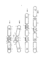
фиг. 1 - трамвай, содержащий два вагона и один соединительный вагон между ними;FIG. 1 - a tram containing two cars and one connecting car between them;
фиг. 2 - трамвай с фиг. 1 на криволинейном участке пути;FIG. 2 - the tram of FIG. 1 on a curved stretch of track;
фиг. 3 - трамвай, в котором вагон без тележки установлен с опорой между двумя соединительными вагонами, а вагоны с тележками соединяются с другими концами соединительных вагонов;FIG. 3 - a tram in which a car without a truck is mounted with a support between two connecting cars, and cars with carts are connected to the other ends of the connecting cars;
фиг. 4 - трамвай, в котором два вагона с тележками соединяются с обеими сторонами соединительного вагона; иFIG. 4 - a tram in which two cars with trolleys are connected to both sides of the connecting car; and
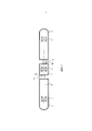
фиг. 5 - модификация трамвая с фиг. 1.FIG. 5 is a modification of the tram of FIG. one.
Осуществление изобретенияThe implementation of the invention
[0016] На фиг. 1 и 2 показан низкопольный трамвай, содержащий два вагона 1 и 2 и установленный между ними соединительный вагон 3, поддерживающий эти вагоны. Вагоны 1 и 2 снабжены тележками 4 и 5, а соединительный вагон 3 снабжен тележкой 6, на которую соединительный вагон 3 опирается своей средней частью с возможностью по существу свободного поворота вокруг одной оси Т поворота в горизонтальной плоскости. Кроме того, между соединительным вагоном 3 и присоединенными к нему вагонами 1 и 2 предусмотрено устройство 7, предназначенное для поддержания горизонтальных углов α и β поворота между обоими присоединенными вагонами 1 и 2 и соединительным вагоном 3 почти равными по величине.[0016] FIG. 1 and 2 show a low-floor tram containing two
[0017] Устройство для поддержания углов α и β поворота равными по величине состоит из рычажного механизма 7, содержащего первую штангу 8, шарнирно соединенную с одним вагоном 1, вторую штангу 9, шарнирно соединенную с другим вагоном 2, и холостой вал 10, который в данном примере установлен с возможностью поворота в горизонтальной плоскости (может быть, разумеется, и в вертикальной плоскости) с соединительным вагоном 3, при этом первая штанга 8 и вторая штанга 9 шарнирно присоединены к противоположным сторонам оси А поворота холостого вала на подобранных расстояниях от оси А поворота, и при этом первая штанга 8 и вторая штанга 9, а также холостой вал 10 расположены на одной стороне рельсового транспортного средства относительно продольной вертикальной центральной плоскости В рельсового транспортного средства. В этом примере первая штанга 8 и вторая штанга 9 имеют различную длину, а холостой вал 10 установлен с возможностью поворота с одной стороны от оси поворота тележки 6 соединительного вагона 3, если смотреть в продольном направлении соединительного вагона 3. Например, рычажный механизм 7 может быть прикреплен, например, к нижним частям конструкций вагонов 1, 2 и 3. Разумеется, рычажный механизм может быть выполнен таким образом, чтобы первая штанга 8 и вторая штанга 9 имели одинаковую длину, а холостой вал 10 был установлен с возможностью поворота рядом с осью поворота тележки 6 соединительного вагона 3, если смотреть в боковом направлении.[0017] A device for maintaining rotation angles α and β consists of a
[0018] На фиг. 2 можно видеть как рычажный механизм 7 сохраняет угол α между вагоном 1 и соединительным вагоном 3, а также угол β между вагоном 2 и соединительным вагоном 3 равными по величине на криволинейном участке пути, обеспечивая вышеописанные существенные преимущества по сравнению с известным уровнем техники.[0018] FIG. 2 it can be seen how the
[0019] На фиг. 3 показан другой вариант осуществления трамвая согласно изобретению, в котором вагон 11 без тележки установлен с опорой между двумя соединительными вагонами 3, в то время как другие концы соединительных вагонов 3 соединены с вагонами 1 и 2, которые снабжены тележками и соответствуют вагонам с фиг. 1 и 2. Рычажные механизмы 7 между соединительными вагонами 3 и вагонами 1, 2 и 11 соответствуют рычажным механизмам, показанным на фиг. 1 и 2 и, разумеется, регулируют углы поворота между вагонами 1, 2, 3 и 11, как на фиг. 1 и 2.[0019] FIG. 3 shows another embodiment of the tram according to the invention, in which a
[0020] На фиг. 4 показан еще один вариант осуществления трамвая согласно изобретению, в котором по два вагона 1, 12 и 2, 13, снабженные тележками, присоединены с каждой стороны соединительного вагона 3, при этом концевые вагоны 1 и 2 являются аналогичными вагонам, показанным на предыдущих чертежах.[0020] FIG. 4 shows another embodiment of the tram according to the invention, in which two
[0021] Устройство для поддержания указанных углов α, β поворота почти равными по величине может также отличаться от рычажного механизма 7, описанного выше. Один такой пример показан на фиг. 5, где устройство 70 для поддержания углов поворота равными по величине содержит гидравлические или пневматические цилиндры 80 и 90, установленные между соединительным вагоном 3 и вагонами 1 и 2, присоединенными к нему, при этом цилиндр 80, расположенный в передней части соединительного вагона 3, и цилиндр 90, расположенный в задней части соединительного вагона 3, расположены на противоположных сторонах продольной вертикальной центральной плоскости В рельсового транспортного средства. Вместо цилиндров 80 и 90 в качестве одного из множества альтернативных устройств для управления углами поворота может быть использовано электромеханическое устройство. Кроме того, для обеспечения надежной работы на обеих сторонах соединительного вагона может быть предусмотрено большее число цилиндров 80 и 90.[0021] A device for maintaining said rotation angles α, β almost equal in magnitude may also differ from the
[0022] Приведенное выше описание предназначено только для иллюстрации основной идеи изобретения. Для специалиста в данной области техники очевидно, что детали изобретения могут быть изменены в пределах объема прилагаемой формулы изобретения. Так, например, число соединенных вагонов может быть изменено по мере необходимости и может отличаться от вышеописанных альтернатив в пределах, установленных изобретением. Изобретение может быть также использовано для рельсовых транспортных средств, отличных от традиционных трамваев, в частности для высокоскоростного трамвайного оборудования.[0022] The above description is intended only to illustrate the basic idea of the invention. For a person skilled in the art it is obvious that the details of the invention can be changed within the scope of the attached claims. So, for example, the number of connected wagons can be changed as necessary and may differ from the above alternatives within the limits established by the invention. The invention can also be used for rail vehicles other than traditional trams, in particular for high-speed tram equipment.
Claims (7)
Applications Claiming Priority (3)
| Application Number | Priority Date | Filing Date | Title |
|---|---|---|---|
| FI20125604 | 2012-06-04 | ||
| FI20125604A FI124938B (en) | 2012-06-04 | 2012-06-04 | The rail vehicle |
| PCT/FI2013/050596 WO2013182746A1 (en) | 2012-06-04 | 2013-06-03 | Rail vehicle |
Publications (2)
| Publication Number | Publication Date |
|---|---|
| RU2014149144A RU2014149144A (en) | 2016-07-27 |
| RU2639366C2 true RU2639366C2 (en) | 2017-12-21 |
Family
ID=49711465
Family Applications (1)
| Application Number | Title | Priority Date | Filing Date |
|---|---|---|---|
| RU2014149144A RU2639366C2 (en) | 2012-06-04 | 2013-06-03 | Rail vehicle |
Country Status (8)
| Country | Link |
|---|---|
| EP (1) | EP2855230B1 (en) |
| JP (1) | JP6230075B2 (en) |
| CN (1) | CN104487311B (en) |
| ES (1) | ES2763953T3 (en) |
| FI (1) | FI124938B (en) |
| PL (1) | PL2855230T3 (en) |
| RU (1) | RU2639366C2 (en) |
| WO (1) | WO2013182746A1 (en) |
Families Citing this family (5)
| Publication number | Priority date | Publication date | Assignee | Title |
|---|---|---|---|---|
| CN108583613B (en) * | 2018-04-13 | 2023-12-01 | 无锡市东鹏金属制品有限公司 | Support piece for high-speed rail traction system |
| DE102018113349A1 (en) * | 2018-06-05 | 2019-12-05 | Bombardier Transportation Gmbh | Swivel joint for a bogie of a rail vehicle |
| CN110104017A (en) * | 2019-04-30 | 2019-08-09 | 中车四方车辆有限公司 | Tramcar |
| CN111845795B (en) * | 2020-07-20 | 2023-07-04 | 中车四方车辆有限公司 | Low-floor tramcar |
| CN115709736B (en) * | 2022-11-07 | 2025-03-28 | 中铁一局集团有限公司 | A special electric device and method suitable for subway track construction in tunnel |
Citations (5)
| Publication number | Priority date | Publication date | Assignee | Title |
|---|---|---|---|---|
| FR2549436A1 (en) * | 1983-07-21 | 1985-01-25 | Renault Vehicules Ind | Articulated road vehicle, especially for the transport of passengers |
| RU2140856C1 (en) * | 1994-06-16 | 1999-11-10 | Лор Эндюстри | Tie with angle compensator between road modules coupled through self-carrying intermediate module |
| US6167814B1 (en) * | 1998-05-27 | 2001-01-02 | Kinki Sharyo Co., Ltd. | Running stabilizing linkage system for the joint of coaches |
| EP1074448A1 (en) * | 1999-08-04 | 2001-02-07 | Liebherr-Aerospace Lindenberg GmbH | Track-bound vehicle, especially railway vehicle for regional transport |
| CN202219788U (en) * | 2011-08-15 | 2012-05-16 | 邦巴尔迪尔运输有限公司 | Vehicle body module for a rail vehicle and rail vehicle |
Family Cites Families (17)
| Publication number | Priority date | Publication date | Assignee | Title |
|---|---|---|---|---|
| CH141733A (en) * | 1929-07-22 | 1930-08-15 | Buderus Carl | Carriages for transporting people or freight. |
| CH623783A5 (en) * | 1978-06-26 | 1981-06-30 | Leriverend Jean Paul Marcel | |
| JPS558928A (en) * | 1978-07-03 | 1980-01-22 | Biire Do Ruuan | Connected automatic vehicles |
| JPS60146751A (en) * | 1984-01-11 | 1985-08-02 | 富士重工業株式会社 | Connecting unit car |
| US5036774A (en) * | 1989-02-21 | 1991-08-06 | Thrall Car Manufacturing Company | Long-travel side bearing for an articulated railroad car |
| CH690032A5 (en) * | 1994-07-13 | 2000-03-31 | Vevey Technologies Sa | A method of setting the orientation of the steerable wheels in rolling devices of a rolling assembly rail and rolling assembly using this method. |
| AT411745B (en) * | 1997-11-07 | 2004-05-25 | Bombardier Wien Schienen | DEVICE FOR CONNECTING TWO NEIGHBORING CARRIERS OF A RAIL VEHICLE |
| FR2809069B1 (en) * | 2000-05-22 | 2003-08-15 | Alstom | RAIL VEHICLE COMPRISING AN END VEHICLE EXTENDED BY A CAB |
| JP2004249894A (en) * | 2003-02-21 | 2004-09-09 | Mitsubishi Heavy Ind Ltd | Low floor type electric car |
| JP4410720B2 (en) * | 2005-04-26 | 2010-02-03 | 三菱重工業株式会社 | Articulated vehicle, articulated device and control method thereof |
| CZ2005436A3 (en) * | 2005-07-04 | 2006-10-11 | VÚKV a.s. | Low-floor sectional rail vehicle, especially tramway |
| JP2007331461A (en) * | 2006-06-13 | 2007-12-27 | Kawasaki Heavy Ind Ltd | Single-axis bogie truck with guide wheels for low-floor railway vehicles |
| JP5121191B2 (en) * | 2006-09-05 | 2013-01-16 | 川崎重工業株式会社 | Low-floor railway vehicles and low-floor trams |
| CN200995690Y (en) * | 2006-12-01 | 2007-12-26 | 西南交通大学 | Forced guide mechanism of hinged equipment for independent wheel |
| JP5127412B2 (en) * | 2007-11-16 | 2013-01-23 | 川崎重工業株式会社 | Anti-roll device between vehicles and railway vehicle |
| JP5051771B2 (en) * | 2008-01-28 | 2012-10-17 | 国立大学法人 東京大学 | Wheel unit, bogie, railway vehicle and railway system |
| JP5010630B2 (en) * | 2009-02-20 | 2012-08-29 | 三菱重工業株式会社 | Low floor vehicle |
-
2012
- 2012-06-04 FI FI20125604A patent/FI124938B/en active IP Right Grant
-
2013
- 2013-06-03 EP EP13800691.1A patent/EP2855230B1/en active Active
- 2013-06-03 PL PL13800691T patent/PL2855230T3/en unknown
- 2013-06-03 WO PCT/FI2013/050596 patent/WO2013182746A1/en not_active Ceased
- 2013-06-03 ES ES13800691T patent/ES2763953T3/en active Active
- 2013-06-03 JP JP2015514548A patent/JP6230075B2/en not_active Expired - Fee Related
- 2013-06-03 CN CN201380029102.XA patent/CN104487311B/en active Active
- 2013-06-03 RU RU2014149144A patent/RU2639366C2/en active
Patent Citations (5)
| Publication number | Priority date | Publication date | Assignee | Title |
|---|---|---|---|---|
| FR2549436A1 (en) * | 1983-07-21 | 1985-01-25 | Renault Vehicules Ind | Articulated road vehicle, especially for the transport of passengers |
| RU2140856C1 (en) * | 1994-06-16 | 1999-11-10 | Лор Эндюстри | Tie with angle compensator between road modules coupled through self-carrying intermediate module |
| US6167814B1 (en) * | 1998-05-27 | 2001-01-02 | Kinki Sharyo Co., Ltd. | Running stabilizing linkage system for the joint of coaches |
| EP1074448A1 (en) * | 1999-08-04 | 2001-02-07 | Liebherr-Aerospace Lindenberg GmbH | Track-bound vehicle, especially railway vehicle for regional transport |
| CN202219788U (en) * | 2011-08-15 | 2012-05-16 | 邦巴尔迪尔运输有限公司 | Vehicle body module for a rail vehicle and rail vehicle |
Also Published As
| Publication number | Publication date |
|---|---|
| EP2855230A4 (en) | 2016-03-30 |
| ES2763953T3 (en) | 2020-06-01 |
| FI124938B (en) | 2015-03-31 |
| EP2855230B1 (en) | 2019-10-09 |
| CN104487311A (en) | 2015-04-01 |
| PL2855230T3 (en) | 2020-05-18 |
| JP6230075B2 (en) | 2017-11-15 |
| EP2855230A1 (en) | 2015-04-08 |
| JP2015522462A (en) | 2015-08-06 |
| RU2014149144A (en) | 2016-07-27 |
| CN104487311B (en) | 2018-01-16 |
| FI20125604L (en) | 2013-12-05 |
| WO2013182746A1 (en) | 2013-12-12 |
Similar Documents
| Publication | Publication Date | Title |
|---|---|---|
| CN101898562B (en) | Passenger transport railcar | |
| CN103507822A (en) | Railway vehicle bogie with improved suspension, in particular for a low floor tramway | |
| CN107554543B (en) | Rail vehicle and articulated tramcar bogie thereof | |
| CN104512431A (en) | Special low-floor hinging type rail vehicle for railroad car | |
| RU2520173C2 (en) | Passenger railcar | |
| CN107097805A (en) | It is exclusively used in the attachment means between straddle-type monorail train railway carriage or compartment | |
| JP6230075B2 (en) | Rail vehicle | |
| KR20120047916A (en) | Railway truck | |
| KR101654896B1 (en) | Space saving bogie for railway car | |
| CN206856725U (en) | The attachment means being exclusively used between straddle-type monorail train railway carriage or compartment | |
| CN102490747B (en) | Light rail vehicle and power bogie thereof | |
| KR101530206B1 (en) | 3-axles articulated bogie for railway vehicle | |
| CN103707898A (en) | Single-hinging device for low-floor tramcar marshalling | |
| RU2329907C1 (en) | Railroad rolling stock two-axle truck | |
| EP1349762B1 (en) | Vehicles transit apparatus | |
| CN104093579B (en) | The multipurpose track vehicles | |
| CN203666688U (en) | Single-hinge device for marshaling of low floor tramcar | |
| CN101007536A (en) | Joint type eight-axle rail freight and its connection style | |
| JPH11208469A (en) | Railcar bogie | |
| RU2308387C1 (en) | Railway traction vehicle with two-axle bogies (versions) | |
| RU2284931C1 (en) | Railway traction vehicle with two-axle bogies | |
| RU2307750C1 (en) | Traction rail vehicle with two-axle bogies (versions) | |
| JP4618903B2 (en) | Single-axle truck for connecting railway vehicles | |
| RU2308386C1 (en) | Railway traction vehicle with two-axle bogies (versions) | |
| RU2323119C1 (en) | Eight-axle railway traction vehicle (versions) |