RU2629165C1 - System and method of transmitting synchronization signal - Google Patents
System and method of transmitting synchronization signal Download PDFInfo
- Publication number
- RU2629165C1 RU2629165C1 RU2016121479A RU2016121479A RU2629165C1 RU 2629165 C1 RU2629165 C1 RU 2629165C1 RU 2016121479 A RU2016121479 A RU 2016121479A RU 2016121479 A RU2016121479 A RU 2016121479A RU 2629165 C1 RU2629165 C1 RU 2629165C1
- Authority
- RU
- Russia
- Prior art keywords
- sequence
- synchronization
- synchronization signal
- primary
- signal
- Prior art date
Links
Images
Classifications
-
- H—ELECTRICITY
- H04—ELECTRIC COMMUNICATION TECHNIQUE
- H04B—TRANSMISSION
- H04B7/00—Radio transmission systems, i.e. using radiation field
- H04B7/14—Relay systems
- H04B7/15—Active relay systems
- H04B7/204—Multiple access
- H04B7/212—Time-division multiple access [TDMA]
-
- H—ELECTRICITY
- H04—ELECTRIC COMMUNICATION TECHNIQUE
- H04J—MULTIPLEX COMMUNICATION
- H04J11/00—Orthogonal multiplex systems, e.g. using WALSH codes
-
- H—ELECTRICITY
- H04—ELECTRIC COMMUNICATION TECHNIQUE
- H04J—MULTIPLEX COMMUNICATION
- H04J11/00—Orthogonal multiplex systems, e.g. using WALSH codes
- H04J11/0069—Cell search, i.e. determining cell identity [cell-ID]
- H04J11/0073—Acquisition of primary synchronisation channel, e.g. detection of cell-ID within cell-ID group
-
- H—ELECTRICITY
- H04—ELECTRIC COMMUNICATION TECHNIQUE
- H04W—WIRELESS COMMUNICATION NETWORKS
- H04W4/00—Services specially adapted for wireless communication networks; Facilities therefor
- H04W4/70—Services for machine-to-machine communication [M2M] or machine type communication [MTC]
-
- H—ELECTRICITY
- H04—ELECTRIC COMMUNICATION TECHNIQUE
- H04W—WIRELESS COMMUNICATION NETWORKS
- H04W56/00—Synchronisation arrangements
- H04W56/001—Synchronization between nodes
-
- H—ELECTRICITY
- H04—ELECTRIC COMMUNICATION TECHNIQUE
- H04W—WIRELESS COMMUNICATION NETWORKS
- H04W72/00—Local resource management
- H04W72/20—Control channels or signalling for resource management
- H04W72/21—Control channels or signalling for resource management in the uplink direction of a wireless link, i.e. towards the network
-
- H—ELECTRICITY
- H04—ELECTRIC COMMUNICATION TECHNIQUE
- H04J—MULTIPLEX COMMUNICATION
- H04J11/00—Orthogonal multiplex systems, e.g. using WALSH codes
- H04J2011/0096—Network synchronisation
-
- H—ELECTRICITY
- H04—ELECTRIC COMMUNICATION TECHNIQUE
- H04J—MULTIPLEX COMMUNICATION
- H04J2211/00—Orthogonal indexing scheme relating to orthogonal multiplex systems
- H04J2211/003—Orthogonal indexing scheme relating to orthogonal multiplex systems within particular systems or standards
- H04J2211/005—Long term evolution [LTE]
-
- H—ELECTRICITY
- H04—ELECTRIC COMMUNICATION TECHNIQUE
- H04W—WIRELESS COMMUNICATION NETWORKS
- H04W88/00—Devices specially adapted for wireless communication networks, e.g. terminals, base stations or access point devices
- H04W88/08—Access point devices
Abstract
Description
Область техники, к которой относится изобретениеFIELD OF THE INVENTION
Настоящее изобретение касается беспроводной связи и, в конкретных вариантах осуществления изобретения, касается системы и способа передачи сигнала синхронизации.The present invention relates to wireless communications and, in specific embodiments, relates to a system and method for transmitting a synchronization signal.
Уровень техникиState of the art
Технология устройство-устройство (D2D) привлекает большое внимание благодаря возможности предложения новых сервисов, улучшения пропускной способности системы и предложения лучшей возможности взаимодействия с пользователем. Определено множество потенциальных случаев использования D2D.Device-to-device (D2D) technology attracts much attention due to the possibility of offering new services, improving system throughput and offering better user experience. Many potential uses for D2D have been identified.
Для обеспечения успешной D2D связи критичным является вопрос синхронизации: пользовательские устройства (UE) D2D передачи и приема должны получать из источника (источников) синхронизации одни и те же сигналы синхронизации по времени и/или частоте. Эти источники должны периодически передавать, по меньшей мере, D2D сигнал (D2DSS) синхронизации для обеспечения синхронизации D2D UE по времени и/или частоте. Источником синхронизации может быть базовая станция, улучшенный NodeB (eNodeB) (в обычной сети технологии «Долгосрочное развитие» (LTE) Проекта партнерства третьего поколения (3GPP)) или D2D UE, в котором ретранслируют канал синхронизации нисходящего канала (DL) от eNodeB.To ensure successful D2D communication, the synchronization issue is critical: D2D transmit and receive user devices (UEs) must receive the same synchronization signals in time and / or frequency from the synchronization source (s). These sources must periodically transmit at least a D2D synchronization signal (D2DSS) to provide synchronization of the D2D UE in time and / or frequency. The synchronization source can be a base station enhanced by NodeB (eNodeB) (in a conventional network of the Long-Term Development (LTE) technology of the Third Generation Partnership Project (3GPP)) or a D2D UE in which the downlink channel synchronization (DL) channel is relayed from the eNodeB.
Раскрытие изобретенияDisclosure of invention
Примеры вариантов осуществления настоящего изобретения, в которых предложена система и способ передачи сигнала синхронизации.Examples of embodiments of the present invention, which proposed a system and method for transmitting a synchronization signal.
В соответствии с примером варианта осуществления настоящего изобретения предложен способ связи типа устройство-устройство. Способ включает в себя следующее: вырабатывают, в источнике синхронизации, первичный сигнал синхронизации устройство-устройство, который отличен от первичного сигнала (PSS) синхронизации, направленного улучшенным NodeB (eNodeB), и который отличен от существующего сигнала восходящего канала (UL), направленного устройствами связи типа устройство-устройство, и передают, в источнике синхронизации, первичный сигнал синхронизации устройство-устройство в форме сигнала (SC-FDMA) множественного доступа с частотным разделением каналов и единственной несущей.In accordance with an example embodiment of the present invention, there is provided a device-to-device communication method. The method includes the following: generating, at the synchronization source, a primary device-device synchronization signal that is different from the primary synchronization signal (PSS) directed by the enhanced NodeB (eNodeB), and which is different from the existing uplink (UL) signal directed by the devices device-to-device communications, and transmit, in a synchronization source, a primary device-to-device synchronization signal in the form of a multiple access frequency-division multiple access (SC-FDMA) signal and a single carrier d.
В соответствии с другим примером варианта осуществления настоящего изобретения предложен способ работы устройства связи типа устройство-устройство. Способ включает в себя следующее: принимают, в устройстве связи типа устройство-устройство, несколько физических блоков (PRB) ресурсов, в том числе первичный сигнал синхронизации устройство-устройство, который отличен от первичного сигнала (PSS) синхронизации, направленного улучшенным NodeB (eNodeB), и который отличен от существующего сигнала восходящего канала (UL), направленного устройствами связи типа устройство-устройство, при этом первичный сигнал синхронизации устройство-устройство передают в форме сигнала (SC-FDMA) множественного доступа с частотным разделением каналов и единственной несущей. Способ также включает в себя следующее: определяют, в устройстве связи типа устройство-устройство, первичный сигнал синхронизации устройство-устройство в нескольких PRB, и осуществляют синхронизацию, в устройстве связи типа устройство-устройство, в соответствии с первичным сигналом синхронизации устройство-устройство.According to another example of an embodiment of the present invention, there is provided a method of operating a device-device-type communication device. The method includes the following: receive, in a device-to-device communication device, several physical blocks (PRB) of resources, including a primary device-device synchronization signal, which is different from a primary synchronization signal (PSS) directed by an improved NodeB (eNodeB) , and which is different from the existing uplink (UL) signal directed by device-device communication devices, while the primary device-device synchronization signal is transmitted in the form of a multiple access signal (SC-FDMA) via -frequency division multiplexing and a single carrier. The method also includes the following: determining, in the device-to-device type communication device, the primary device-device synchronization signal in several PRBs, and synchronizing, in the device-device type communication device, in accordance with the primary device-device synchronization signal.
В соответствии с другим примером варианта осуществления настоящего изобретения предложен источник синхронизации. Источник синхронизации содержит процессор и устройство передачи, функционально соединенное с процессором. В процессоре вырабатывают первичный сигнал синхронизации устройство-устройство, который отличен от первичного сигнала (PSS) синхронизации, направленного улучшенным NodeB (eNodeB), и который отличен от существующего сигнала восходящего канала (UL), направленного устройствами связи типа устройство-устройство. В устройстве передачи передают первичный сигнал синхронизации устройство-устройство в форме сигнала (SC-FDMA) множественного доступа с частотным разделением каналов и единственной несущей.In accordance with another example embodiment of the present invention, a synchronization source is provided. The synchronization source comprises a processor and a transmission device operably connected to the processor. A primary device-device synchronization signal is generated in the processor, which is different from the primary synchronization signal (PSS) directed by the Enhanced NodeB (eNodeB), and which is different from the existing uplink (UL) signal directed by device-device communication devices. In the transmission device, the primary device-device synchronization signal is transmitted in the form of a multiple access, single-carrier, multiple-access signal (SC-FDMA).
В соответствии с еще одним примером варианта осуществления настоящего изобретения предложен способ для связи типа устройство-устройство. Способ включает в себя следующее: вырабатывают, в источнике синхронизации, первичный сигнал синхронизации устройство-устройство в соответствии сIn accordance with another example embodiment of the present invention, a method for device-device communication is provided. The method includes the following: generate, in the source of synchronization, the primary synchronization signal device-device in accordance with


и при этом первичную последовательность синхронизации устройство-устройство соотносят, самое большее, с N коэффициентами Фурье H[], где Ts является периодом выборки, Δƒ является промежутком между поднесущими, u является первым индексом корня, N является целым числом и δ=1/2. Способ включает в себя следующее: передают, в источнике синхронизации, первичный сигнал синхронизации устройство-устройство в форме сигнала (SC-FDMA) множественного доступа с частотным разделением каналов и единственной несущей.and in this case, the primary synchronization sequence of the device-device is correlated, at most, with N Fourier coefficients H [], where T s is the sampling period, Δƒ is the interval between subcarriers, u is the first root index, N is an integer and δ = 1 / 2. The method includes the following: transmitting, in a synchronization source, a primary device-to-device synchronization signal in the form of a signal (SC-FDMA) of multiple access with frequency division multiplexing and a single carrier.
Одно преимущество варианта осуществления изобретения заключается в том, что использование центрально симметричных сигналов уменьшает сложность декодирования.One advantage of an embodiment of the invention is that the use of centrally symmetric signals reduces the decoding complexity.
Краткое описание чертежейBrief Description of the Drawings
Для более полного понимания настоящего изобретения и его преимуществ далее приведено подробное описание со ссылками на приложенные чертежи, на которых:For a more complete understanding of the present invention and its advantages, the following is a detailed description with reference to the attached drawings, in which:
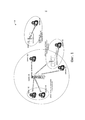
фиг. 1 - вид, показывающий пример системы связи, соответствующей описанным здесь примерам вариантов осуществления изобретения;FIG. 1 is a view showing an example of a communication system corresponding to examples of embodiments of the invention described herein;
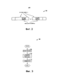
фиг. 2 - вид, показывающий пример подкадров, соответствующих описанным здесь примерам вариантов осуществления изобретения;FIG. 2 is a view showing an example of subframes corresponding to examples of embodiments of the invention described herein;
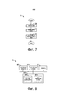
фиг. 3 - вид, показывающий блок-схему примеров операций, осуществляемых в D2D UE в соответствии с описанными здесь примерами вариантов осуществления изобретения;FIG. 3 is a view showing a flowchart of examples of operations performed in a D2D UE in accordance with examples of embodiments of the invention described herein;
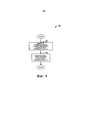
фиг. 4 - вид, показывающий блок-схему примеров операций, осуществляемых в D2D UE тогда, когда в D2D UE вырабатывают D2DSS в соответствии с описанными здесь примерами вариантов осуществления изобретения;FIG. 4 is a view showing a flowchart of examples of operations carried out in a D2D UE when D2DSS is generated in a D2D UE in accordance with examples of embodiments of the invention described herein;
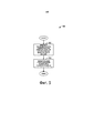
фиг. 5 - вид, показывающий блок-схему примеров операций, осуществляемых в D2D UE тогда, когда в D2D UE вырабатывают D2DSS в соответствии с ZC последовательностью с другим индексом корня в соответствии с описанными здесь примерами вариантов осуществления изобретения;FIG. 5 is a view showing a flowchart of examples of operations performed in a D2D UE when a D2DSS is generated in a D2D UE in accordance with a ZC sequence with a different root index in accordance with examples of embodiments of the invention described herein;
фиг. 6 - вид, показывающий пример вычислительной платформы, которая может быть использована для реализации, например, описанных здесь устройств и способов, в соответствии с описанными здесь примерами вариантов осуществления изобретения;FIG. 6 is a view showing an example of a computing platform that can be used to implement, for example, the devices and methods described herein, in accordance with examples of embodiments of the invention described herein;
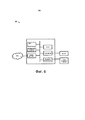
фиг. 7 - вид, показывающий блок-схему примеров операций, осуществляемых при синхронизации устройства D2D связи с использованием D2DSS в соответствии с описанными здесь примерами вариантов осуществления изобретения;FIG. 7 is a view showing a flowchart of examples of operations performed when synchronizing a communication device D2D using D2DSS in accordance with examples of embodiments of the invention described herein;
фиг. 8 - вид, показывающий пример устройства связи, соответствующего описанным здесь примерам вариантов осуществления изобретения.FIG. 8 is a view showing an example of a communication device corresponding to examples of embodiments of the invention described herein.
Осуществление изобретенияThe implementation of the invention
Ниже подробно описано функционирование текущих примеров вариантов осуществления изобретения и их структура. Тем не менее, ясно, что в настоящем изобретении предложено много применимых идей изобретения, которые могут быть реализованы в широком наборе конкретных ситуаций. Обсуждаемые конкретные варианты осуществления изобретения приведены просто для иллюстрации конкретных структур изобретения и способов его функционирования и не ограничивают объема изобретения.The functioning of the current examples of embodiments of the invention and their structure are described in detail below. However, it is clear that the present invention provides many applicable ideas of the invention that can be implemented in a wide range of specific situations. Discussed specific embodiments of the invention are provided merely to illustrate specific structures of the invention and methods of its operation and do not limit the scope of the invention.
Настоящее изобретение будет описано в виде примеров вариантов осуществления изобретения в конкретной ситуации, а именно в ситуации систем связи, в которых используют сигнал синхронизации для облегчения D2D связи. Изобретение может быть применено в соответствующих стандартам системах связи, таких как системы, соответствующие Проекту партнерства третьего поколения (3GPP), IEEE 802.11, и подобных, техническим стандартам, и в системах связи, не соответствующих стандартам, в которым используют сигнал синхронизации для облегчения D2D связи.The present invention will be described as examples of embodiments of the invention in a particular situation, namely in the situation of communication systems that use a synchronization signal to facilitate D2D communication. The invention can be applied to standards-compliant communications systems, such as those compliant with the Third Generation Partnership Project (3GPP), IEEE 802.11, and the like, technical standards, and non-standards-based communications systems that use a clock signal to facilitate D2D communications .
На фиг. 1 показан пример системы 100 связи. Система 100 связи поддерживает D2D связь и, следовательно, может называться D2D системой. На фиг. 1 показана D2D синхронизация в D2D системе. Как показано на фиг. 1, D2DUE1 105, D2DUE2 110 и D2DUE3 115 могут обеспечивать синхронизацию по времени и/или частоте на основе существующего канала синхронизации LTE DL, такого как первичный сигнал (PSS) синхронизации и вторичный сигнал (SSS) синхронизации, направленные eNodeB 120, или других сигналов синхронизации, направленных eNodeB 120. В то же время D2DUE3 115 и D2DUE5 125 также играют роль источников синхронизации (то есть источников D2D синхронизации) соответственно для D2DUE4 130 и D2DUE6 135. eNodeB также можно называть NodeB, контроллерами, базовыми станциями, точками доступа, базовыми станциями конечных станций и подобным образом. Аналогично, UE также можно называть мобильными станциями, конечными станциями, пользователями, станциями, абонентами и подобным образом. Хотя ясно, что системы связи могут использовать несколько eNodeB, которые способны обмениваться информацией с несколькими UE, для простоты показана только одна eNodeB и несколько UE.In FIG. 1 shows an example of a
Обнаружение представляет собой D2D технологию, которая включает в себя способность обнаруживать соседние UE. Обнаружение может быть или обнаружением с помощью eNodeB, или открытым обнаружением. При обнаружении с помощью eNodeB первое UE направлено на передачу сигнала (например, зондирующего опорного сигнала (SRS)), а второму UE необходимо слушать и отчитываться в eNodeB о качестве сигнала. В eNodeB могут на основе этого качества сигнала из отчета решить, могут ли эти две UE поддержать сервис ProSe. При открытом обнаружении в любом UE могут передавать сигнал, такой как маячковый сигнал, для уведомления других UE о своем присутствии. Заметим, что этот процесс может включать в себя неактивные UE.Discovery is a D2D technology that includes the ability to detect neighboring UEs. The discovery can be either discovery using the eNodeB or open discovery. When detected by the eNodeB, the first UE is directed to transmit a signal (for example, a sounding reference signal (SRS)), and the second UE needs to listen and report to the eNodeB about the signal quality. The eNodeBs can, based on this signal quality, decide from the report whether these two UEs can support the ProSe service. With open detection, a signal, such as a beacon, can be transmitted to any UEs to notify other UEs of their presence. Note that this process may include inactive UEs.
При условии, что этот процесс может включать в себя неактивные UE, обычно его осуществляют с очень ограниченной доступной информацией. В частности, в UE обычно должны опираться на информацию, транслированную eNodeB. В большинстве ситуаций может быть слишком дорого активизировать эти UE и передавать на них сигналы управления (RRC) радиоресурсами. Более того, расположение неактивного UE является приблизительным, и в системе связи не известна точная ячейка, которая обслуживает UE.Provided that this process may include inactive UEs, it is usually carried out with very limited available information. In particular, UEs should typically rely on information broadcast by the eNodeB. In most situations, it may be too expensive to activate these UEs and transmit radio resource control (RRC) signals to them. Moreover, the location of the inactive UE is approximate, and the exact cell that serves the UE is not known in the communication system.
Для D2D связи также в целом предполагают, что D2D имеет место по восходящему (UL) участку полосы пропускания, так как для UL взаимные помехи будут наносить меньший вред сотовым UE. По UL передача D2D UE создает помехи eNodeB. В результате, пока D2D UE находится на приемлемом расстоянии от eNodeB, помехи, созданные D2D UE, имеют небольшое влияние. В противоположность сказанному, для DL D2D помехи воздействуют на соседние UE и потенциально воздействуют на их возможность принимать каналы синхронизации и PDCCH, и это может привести к значительно большему воздействию по сравнению со случаем, когда в D2D UE передают по UL.For D2D communications, it is also generally assumed that D2D occurs in the upstream (UL) portion of the bandwidth, since for UL, interference will cause less harm to the cellular UEs. On UL, D2D transmission of the UE interferes with the eNodeB. As a result, while the D2D UE is at an acceptable distance from the eNodeB, the interference created by the D2D UE has little effect. In contrast, for DL D2D, interference affects neighboring UEs and potentially affects their ability to receive synchronization channels and PDCCHs, and this can lead to a significantly greater impact compared to the case when UEs are transmitted on UL in D2D.
При условии, что D2D связь осуществляют по UL, логично предположить, что D2D обнаружение осуществляют также по UL. В случае открытого обнаружения, для обнаружения резервируют заданное количество подкадров (например, 1%). Во время этих подкадров обычно совсем не осуществляют сотовую связь. Передают только сигналы UE обнаружения. На фиг. 2 показан пример подкадров 200. Некоторые подкадры 200 используют как подкадры обнаружения (показаны заштрихованными ячейками), а другие используют как сотовые подкадры (показаны незаштрихованными ячейками).Provided that D2D communication is carried out by UL, it is logical to assume that D2D detection is also carried out by UL. In the case of open detection, a predetermined number of subframes are reserved for detection (e.g., 1%). During these subframes, cellular communication is generally not performed at all. Only transmit detection UE signals. In FIG. 2 shows an example of
В соответствии с примером варианта осуществления изобретения предложены примеры D2D сигналов синхронизации. Принципы разработки D2DSS могут включать в себя одно или более из следующего:In accordance with an example embodiment of the invention, examples of D2D synchronization signals are provided. D2DSS development principles may include one or more of the following:
- хорошие характеристики автокорреляции и взаимной корреляции, аналогичные случаю обычного PSS (например, на основе ZC последовательностей);- good autocorrelation and cross-correlation characteristics, similar to the case of ordinary PSS (for example, based on ZC sequences);
- отличный от обычного PSS, что нужно для избежания неопределенности D2D UE и простого включения сотовых UE;- different from the usual PSS, which is necessary to avoid the uncertainty of the D2D UE and the simple inclusion of cellular UE;
- хорошие характеристики взаимной корреляции относительно перекрытия с сигналами восходящего канала, такими как опорный сигнал (DMRS) демодуляции для восходящего канала, так как D2D сигнал будут передавать в спектре/подкадре UL;- good cross-correlation characteristics with respect to overlap with uplink signals, such as demodulation reference signal (DMRS) for the uplink, since the D2D signal will be transmitted in the UL spectrum / subframe;
- возможное указание D2D рабочих параметров, тем самым, позволяет D2D UE быстро получать D2D конфигурационную информацию; и- a possible indication of D2D operating parameters, thereby allowing the D2D UE to quickly obtain D2D configuration information; and
- возможная поддержка тонкой синхронизации по времени и/или частоте на основе D2DSS, в то время как PSS и/или SSS системы LTE могут поддерживать только грубую синхронизацию по времени и/или частоте.- possible support for fine synchronization in time and / or frequency based on D2DSS, while PSS and / or SSS LTE systems can only support coarse synchronization in time and / or frequency.
Кроме того, может быть обеспечена обратная совместимость, так как существующее UE не должно быть способно определить D2DSS, что предотвратит существующее UE от ошибочного предположения, что D2D UE (источник D2DSS) является eNodeB. Заметим, что описанные здесь примеры вариантов осуществления изобретения могут быть объединены.In addition, backward compatibility can be ensured since the existing UE should not be able to determine D2DSS, which would prevent the existing UE from mistakenly assuming that the D2D UE (source of D2DSS) is an eNodeB. Note that examples of embodiments of the invention described herein may be combined.
Более того, определение D2DSS обычно заключает в себя некоторую форму согласованной фильтрации в устройстве приема, например, определение корреляции между принятым сигналом и D2DSS. Так как это включает в себя осуществление большого количества умножений комплексных чисел, задача состоит в том, чтобы так разработать D2DSS, чтобы он обладал такими свойствами сигнала, которые могут быть использованы для уменьшения сложности определения.Moreover, the definition of D2DSS usually includes some form of matched filtering in the receiving device, for example, determining the correlation between the received signal and D2DSS. Since this involves the implementation of a large number of multiplications of complex numbers, the challenge is to design D2DSS in such a way that it possesses signal properties that can be used to reduce the complexity of the determination.
На фиг. 3 показана блок-схема примеров операций 300, осуществляемых в D2D UE. Операции 300 могут иллюстрировать операции, осуществляемые в D2D UE.In FIG. 3 is a flowchart of examples of
Операции 300 могут начаться с того, что в D2D UE вырабатывают D2DSS (блок 305). В D2D UE могут выработать последовательность для D2DSS (например, PD2DSS и/или SD2DSS). Подробности примеров вариантов осуществления D2DSS приведены ниже. В D2D UE могут соотнести последовательность D2DSS, получив преобразованный D2DSS (блок 310). В D2D UE могут соотнести последовательность D2DSS с поднесущими так, что, например, D2DSS станет центрально симметричным. В D2D UE могут передать преобразованный D2DSS (блок 315). Как описано ранее, преобразованный D2DSS может быть передан в UL ресурсах или подкадрах.
В соответствии с примером варианта осуществления изобретения D2DSS основан на ZC последовательности, длина которой отличается от длины других ZC последовательностей, используемых в системе связи. В источнике синхронизации передают D2DSS, на основе чего группа D2D UE (образующая D2D группу) обеспечивает синхронизацию по времени и/или частоте. D2DSS может содержать, по меньшей мере, первичный D2DSS (PD2DSS), где PD2DSS вырабатывают из первой ZC последовательности, при этом длина первой ZC последовательности отлична от длины второй ZC последовательности, используемой для выработки существующего LTE PSS, направленного eNodeB (ZC последовательность, используемая для выработки существующего LTE PSS, является последовательностью длиной 63 и центральный элемент которой выкалывают с целью получения последовательности длиной 62), а также любой возможной ZC последовательности, используемой для выработки существующих UL опорных сигналов (в том числе DMRS и SRS), направленных UE.According to an example embodiment, D2DSS is based on a ZC sequence, the length of which is different from the length of other ZC sequences used in the communication system. D2DSS is transmitted in the synchronization source, on the basis of which the D2D UE group (forming the D2D group) provides synchronization in time and / or frequency. D2DSS may comprise at least primary D2DSS (PD2DSS), where PD2DSS is generated from the first ZC sequence, wherein the length of the first ZC sequence is different from the length of the second ZC sequence used to generate the existing LTE PSS directed by the eNodeB (ZC sequence used for generating an existing LTE PSS is a sequence of length 63 and the central element of which is punctured in order to obtain a sequence of length 62), as well as any possible ZC sequence used to generate substantial UL reference signals (including DMRS and SRS) directed by the UE.
В первом примере, в источнике синхронизации, который является или eNodeB, или D2D UE, передают D2DSS, на основе чего в группе D2D UE (образующая D2D группу) обеспечивается синхронизация по времени/частоте. D2DSS должна содержать, по меньшей мере, первичный D2DSS (PD2DSS), где PD2DSS вырабатывают из первой ZC последовательности и где длина первой ZC последовательности отличается от длины второй ZC последовательности, используемой для выработки существующего LTE PSS. Использование ZC последовательностей разных длин обеспечивает отсутствие ложного определения D2D UE как eNodeB. Другими словами, PD2DSS не будет принят по ошибке за PSS. Кроме того, длина ZC последовательности отличается от любой возможной длины ZC последовательности, используемой для выработки существующих UL опорных сигналов (в том числе DMRS и SRS), направленных UE.In the first example, D2DSS is transmitted to the synchronization source, which is either an eNodeB or D2D UE, based on which time / frequency synchronization is provided in the D2D UE group (forming the D2D group). D2DSS must contain at least primary D2DSS (PD2DSS), where PD2DSS is generated from the first ZC sequence and where the length of the first ZC sequence is different from the length of the second ZC sequence used to generate the existing LTE PSS. The use of ZC sequences of different lengths ensures that there is no false definition of a D2D UE as an eNodeB. In other words, PD2DSS will not be mistaken for PSS. In addition, the length of the ZC sequence is different from any possible length of the ZC sequence used to generate existing UL reference signals (including DMRS and SRS) directed by the UE.
Более того, длина первой ZC последовательности должна быть простым числом или числом, второй наименьший положительный делитель которого больше 3.Moreover, the length of the first ZC sequence must be a prime number or a number whose second smallest positive divisor is greater than 3.
На фиг. 4 показана блок-схема примеров операций 400, осуществляемых в D2D UE тогда, когда в D2D UE вырабатывают D2DSS. Операции 400 могут иллюстрировать операции, осуществляемые в D2D UE тогда, когда в D2D UE вырабатывают D2DSS.In FIG. 4 is a flowchart of examples of
Операции 400 могут начинаться выбором в D2D UE первой ZC последовательности, длина которой отлична от длины второй ZC последовательности, используемой для выработки существующего LTE PSS (блок 405). Более того, длина первой ZC последовательности также отлична от длины других ZC последовательностей, используемых для выработки существующих сигналов, передаваемых D2D UE, таких как UL опорные сигналы (в том числе DMRS и SRS). Кроме того, длина первой ZC последовательности может быть простым числом или числом, второй наименьший положительный делитель которого больше 2. В D2D UE могут вырабатывать D2DSS с использованием первой ZC последовательности (блок 410).
Описываемые здесь операции 400 концентрируются на D2D UE, в котором вырабатывают D2DSS. Тем не менее, в другом объекте в системе связи может быть возможно выработать D2DSS для D2D UE и предоставить D2DSS в D2D UE. Операции 400 могут быть выполнены в любом объекте в системе связи. Следовательно, рассмотрение D2D UE, в котором осуществляют операции 400, не должно считаться ограничением или идеи, или объема примеров вариантов осуществления изобретения.The
На основе этого рассмотрения может быть получена длина ZC последовательности, используемой для D2DSS (например, PD2DSS), в предположении, что в источнике синхронизации передают PD2DSS в 6 физических блоках (PRB) ресурсов (72 поднесущие, как в существующем LTE PSS) в частотной области. Длина ZC последовательности может быть определена на основе следующих принципов:Based on this consideration, the length of the ZC sequence used for D2DSS (e.g., PD2DSS) can be obtained under the assumption that PD2DSS is transmitted in 6 physical resource blocks (PRB) of the synchronization source (72 subcarriers, as in existing LTE PSS) in the frequency domain . The length of the ZC sequence can be determined based on the following principles:
- простое число или число, второй наименьший положительный делитель которого больше 3;- a prime number or a number whose second smallest positive divisor is greater than 3;
- не равна 63 (длина ZC последовательности, используемой в существующем LTE PSS); и- not equal to 63 (the length of the ZC sequence used in the existing LTE PSS); and
- не равна 71, 31 или 47, где 71, 31, 47 являются возможными длинами ZC последовательностей, используемых для UL DMRS.- not equal to 71, 31 or 47, where 71, 31, 47 are the possible lengths of ZC sequences used for UL DMRS.
Если все принципы соблюдены, то длина первой ZC последовательности может быть равной 61, 65 или 67. Заметим, что 67 является максимальным значением, которое не больше 72 и удовлетворяет приведенным выше принципам, при этом 61 является максимальным значением, которое не больше 64 и удовлетворяет приведенным выше принципам, а 65 является значением, второй наименьший положительный делитель которого равен 5 и которое удовлетворяет приведенным выше принципам. В обычном устройстве приема частота выборки может принимать только определенные значения, например, быть степенью числа 2. В качестве иллюстративного примера, если длина последовательности не больше 64, может быть использовано окно устройства приема из 64 отсчетов и, аналогично, если длина последовательности больше 64, но меньше 128, то может быть использовано окно устройства приема в 128 отсчетов. Длина окна устройства приема связана с количеством умножений комплексных чисел, нужных для определения PD2DSS. Сравнивая 61 и 67 как возможные значения длины, если длина первой ZC последовательности равна 61, то на PD2DSS нужно только 64 комплексных отсчета, что приводит к меньшей сложности. Если длина первой ZC последовательности равна 67, то на PD2DSS нужно 128 комплексных отсчетов, что приводит к большей сложности. С другой стороны, если длина первой ZC последовательности равна 67, может быть достигнута меньшая взаимная корреляция. Таким образом, необходимо рассматривать эту длину, если она значительно улучшит эффективность.If all the principles are followed, then the length of the first ZC sequence can be equal to 61, 65, or 67. Note that 67 is the maximum value that is no more than 72 and satisfies the above principles, while 61 is the maximum value that is no more than 64 and satisfies the above principles, and 65 is the value whose second smallest positive divisor is 5 and which satisfies the above principles. In a conventional receiving device, the sampling frequency can take only certain values, for example, be a power of 2. As an illustrative example, if the sequence length is not more than 64, a window of a receiving device of 64 samples can be used and, similarly, if the sequence length is more than 64 but less than 128, then the window of the reception device in 128 samples can be used. The window length of the reception device is related to the number of complex number multiplications needed to determine PD2DSS. Comparing 61 and 67 as possible length values, if the length of the first ZC sequence is 61, then on PD2DSS only 64 complex samples are needed, which leads to less complexity. If the length of the first ZC sequence is 67, then PD2DSS needs 128 complex samples, which leads to greater complexity. On the other hand, if the length of the first ZC sequence is 67, less cross-correlation can be achieved. Thus, it is necessary to consider this length if it significantly improves efficiency.
ZC последовательность с нечетной длиной (например, N=61) может быть определена следующим образом:An odd length ZC sequence (e.g., N = 61) can be defined as follows:

где u - индекс корня, 0<u≤N-1.where u is the root index, 0 <u≤N-1.
Кандидаты на индекс корня для PD2DSS должны быть выбраны для достижения насколько возможно малой взаимной корреляции с существующим PSS. То есть кандидаты на индекс должны быть выбраны из следующего множества: {4, 7, 9, 11, 13, 15, 16, 17, 18, 19, 23, 29, 32, 38, 42, 43, 44, 45, 46, 48, 50, 52, 54, 57}.Candidates for the root index for PD2DSS should be selected to achieve as little cross-correlation as possible with the existing PSS. That is, candidates for the index should be selected from the following set: {4, 7, 9, 11, 13, 15, 16, 17, 18, 19, 23, 29, 32, 38, 42, 43, 44, 45, 46 , 48, 50, 52, 54, 57}.
Источник синхронизации может содержать, по меньшей мере, D2DSS, где D2DSS также должен содержать вторичный D2DSS (SD2DSS), при этом SD2DSS вырабатывают по первой m-последовательности, где длина SD2DSS должна отличаться от длины существующей SSS, направленной eNodeB, и/или отличаться от длины первой ZC последовательности. Это обеспечивает лучшую синхронизацию и позволяет в узле передачи передавать дополнительную информацию, такую как индекс кадра или его эквивалент, если он находится вне зоны покрытия. Кроме того, длина последовательности и полоса пропускания SD2DSS должны быть больше или равны длине последовательности и полосе пропускания PD2DSS.The synchronization source may contain at least D2DSS, where D2DSS must also contain secondary D2DSS (SD2DSS), wherein SD2DSS is generated in the first m-sequence, where the length of SD2DSS must be different from the length of the existing SSS directed by the eNodeB and / or different from lengths of the first ZC sequence. This provides better synchronization and allows additional information, such as the frame index or its equivalent, if it is outside the coverage area, to be transmitted in the transmission node. In addition, the sequence length and SD2DSS bandwidth must be greater than or equal to the PD2DSS sequence length and bandwidth.
Индекс корня первой ZC последовательности может быть определен в соответствии, по меньшей мере, с одним из следующего:The root index of the first ZC sequence can be determined in accordance with at least one of the following:
- полоса пропускания SD2DSS; и- bandwidth SD2DSS; and
- индекс корня первой ZC последовательности и/или первой т-последовательности, которые определены в соответствии, по меньшей мере, с одним из следующего:- the root index of the first ZC sequence and / or the first t-sequence, which are defined in accordance with at least one of the following:
- D2D рабочая полоса пропускания;- D2D working bandwidth;
- идентификационная информация источника синхронизации, например, UE-ID, если источник является D2D UE;- synchronization source identification information, for example, a UE-ID, if the source is a D2D UE;
- тип источника синхронизации, в том числе eNodeB или D2D UE;- type of synchronization source, including eNodeB or D2D UE;
- приоритет источника синхронизации;- priority of the synchronization source;
- идентификационная информация D2DUE группы;- identification information of the D2DUE group;
- тип D2DUE группы; и- type D2DUE group; and
- приоритет D2DUE группы.- The priority of the D2DUE group.
Индекс корня ZC последовательности для PD2DSS (среди всех упомянутых выше кандидатов) также может нести информацию, касающуюся расположения и/или полосы пропускания соответствующего SD2DSS, а также D2D рабочую полосу пропускания этой D2D группы, где кандидаты на полосу пропускания включают в себя: 1,4 МГц, 3 МГц, 5 МГц, 10 МГц, 15 МГц или 20 МГц (6RB, 15RB, 25RB, 50RB, 75RB или 100RB, где RB - блок ресурсов, определенный в LTE системе). Пример использования такого указания проиллюстрирован в приведенной ниже таблице 1. 
В этой ситуации длина и полоса пропускания SD2DSS могут отличаться соответственно от длины и полосы пропускания PD2DSS. Заметим, что большая полоса пропускания SD2DSS (по сравнению с PD2DSS) может помочь D2D UE в D2D группе достигать тонкой синхронизации по времени и/или частоте, что отлично от цели разработки PSS и/или SSS в LTE системе связи.In this situation, the length and bandwidth of the SD2DSS may differ respectively from the length and bandwidth of the PD2DSS. Note that the larger SD2DSS bandwidth (compared to PD2DSS) can help the D2D UE in the D2D group achieve fine synchronization in time and / or frequency, which is different from the goal of developing PSS and / or SSS in an LTE communication system.
В соответствии с примером варианта осуществления изобретения D2DSS основан на ZC последовательности с другим индексом корня для ZC последовательности. В целом, две последовательности, выработанные из единственной последовательности с разными индексами корня, будут разными последовательностями. Другое решение можно получить в предположении, что в источнике синхронизации передают PD2DSS в 6 PRB (72 поднесущие, как в существующем LTE PSS) в частотной области. Первая ZC последовательность может быть определена на основе следующих принципов:According to an example embodiment, D2DSS is based on a ZC sequence with a different root index for the ZC sequence. In general, two sequences derived from a single sequence with different root indices will be different sequences. Another solution can be obtained by assuming that the PD2DSS is transmitted at 6 clocks at the synchronization source (72 subcarriers, as in the existing LTE PSS) in the frequency domain. The first ZC sequence can be determined based on the following principles:
- простое число или число, второй наименьший положительный делитель которого больше 3;- a prime number or a number whose second smallest positive divisor is greater than 3;
- длина должна быть равна 71, где 71 является возможной длиной UL DMRS для передачи 6 PRB;- the length should be 71, where 71 is a possible length of UL DMRS for transmitting 6 PRBs;
- индексы корней должны отличаться от индексов корней, используемых в UL DMRS для передачи 6 PRB;- the root indices must be different from the root indices used in UL DMRS to transmit 6 PRBs;
- если все принципы соблюдены, то длина первой ZC последовательности может быть равной 71. Кандидаты на индексы корней первой ZC последовательности должны быть выбраны из множества {0, 1, 8, 15, 24, 31, 40, 47, 56, 63}.- if all the principles are observed, then the length of the first ZC sequence can be equal to 71. Candidates for the indices of the roots of the first ZC sequence should be selected from the set {0, 1, 8, 15, 24, 31, 40, 47, 56, 63}.
На фиг. 5 показана блок-схема примеров операций 500, осуществляемых в D2D UE тогда, когда в D2D UE вырабатывают D2DSS в соответствии с ZC последовательностью с другим индексом корня. Операции 500 могут иллюстрировать операции, осуществляемые в D2D UE тогда, когда в D2D UE вырабатывают D2DSS в соответствии с ZC последовательностью с другим индексом корня.In FIG. 5 is a flowchart of examples of
Операции 500 могут начинаться с выбора в D2D UE первой ZC последовательности с индексом корня, отличным от индекса корня второй ZC последовательности, используемой для выработки существующего LTE PSS (блок 505). Более того, индекс корня первой ZC последовательности также отличен от индексов корней других ZC последовательностей, используемых для выработки существующих сигналов, передаваемых D2D UE, таких как UL опорные сигналы (в том числе DMRS и SRS). Кроме того, длина первой ZC последовательности может быть равна длине последовательности, используемой для выработки UL DMRS. В D2D UE могут вырабатывать D2DSS с использованием первой ZC последовательности (блок 510).
Описываемые здесь операции 500 концентрируются на D2D UE, в котором вырабатывают D2DSS. Тем не менее, в другом объекте в системе связи может быть возможно выработать D2DSS для D2D UE и предоставить D2DSS в D2D UE. Операции 500 могут быть выполнены в любом объекте в системе связи. Следовательно, рассмотрение D2D UE, в котором осуществляют операции 500, не должно считаться ограничением или идеи, или объема примеров вариантов осуществления изобретения.The
Более того, D2DSS может также содержать вторичный D2DSS (SD2DSS), где SD2DSS вырабатывают с помощью m-последовательности, при этом длина и занимаемая полоса пропускания SD2DSS отличаются от длины и занимаемой полосы пропускания существующей SSS, направляемой eNodeB.Moreover, D2DSS may also contain secondary D2DSS (SD2DSS), where SD2DSS is generated using the m-sequence, and the length and occupied bandwidth of SD2DSS are different from the length and occupied bandwidth of the existing SSS routed by eNodeB.
Индекс корня ZC последовательности для PD2DSS (среди всех упомянутых выше кандидатов) также может нести информацию о расположении и/или полосе пропускания соответствующего SD2DSS, а также D2D рабочую полосу пропускания этой D2D группы, где кандидаты на полосу пропускания включают в себя 1,4 МГц, 3 МГц, 5 МГц, 10 МГц, 15 МГц или 20 МГц (6RB, 15RB, 25RB, 50RB, 75RB, 100RB, где RB - блок ресурсов, определенный в LTE системе). Пример использования такого указания проиллюстрирован в приведенной ниже таблице 2.The ZC root index index for PD2DSS (among all the candidates mentioned above) can also carry information about the location and / or bandwidth of the corresponding SD2DSS, as well as the D2D working bandwidth of this D2D group, where the bandwidth candidates include 1.4 MHz, 3 MHz, 5 MHz, 10 MHz, 15 MHz or 20 MHz (6RB, 15RB, 25RB, 50RB, 75RB, 100RB, where RB is the resource block defined in the LTE system). An example of the use of such an indication is illustrated in Table 2 below.

В этой ситуации длина и полоса пропускания SD2DSS могут отличаться соответственно от длины и полосы пропускания PD2DSS. Заметим, что большая полоса пропускания SD2DSS (по сравнению с PD2DSS) может помочь D2D UE в D2D группе достигать тонкой синхронизации по времени и/или частоте, что отлично от цели разработки PSS и/или SSS в LTE системе связи.In this situation, the length and bandwidth of the SD2DSS may differ respectively from the length and bandwidth of the PD2DSS. Note that the larger SD2DSS bandwidth (compared to PD2DSS) can help the D2D UE in the D2D group achieve fine synchronization in time and / or frequency, which is different from the goal of developing PSS and / or SSS in an LTE communication system.
Что касается соотнесения сигнала PD2DSS, PD2DSS может быть получен как преобразование множества коэффициентов (Фурье) частотной области. В качестве не ограничивающего изобретение примера предположим, что дискретный, временной области сигнал основного диапазона получен следующим образом:Regarding the correlation of the PD2DSS signal, PD2DSS can be obtained as a transform of the set of Fourier coefficients of the frequency domain. As a non-limiting example of the invention, suppose that a discrete, time-domain main range signal is obtained as follows:
![]()
![]()
иand
![]()
![]()
для множества частотных коэффициентов Фурье Hu[![]()
![]()
![]()
![]()
Если последовательность xu(![]()
![]()
![]()
![]()
![]()
![]()
![]()

![]()
![]()
![]()
![]()
![]()
![]()
![]()
В качестве иллюстративного примера, соответствующий непрерывный OFDM сигнал основного диапазона (за исключением циклического префикса) вырабатывают следующим образом (с использованием периодичности дискретного преобразования Фурье ![]()
![]()

где Ts является периодом выборки, Δƒ является промежутком между поднесущими и N=1/TsΔƒ. Это то же самое, что N является количеством поднесущих OFDM сигнала. Для упрощения обозначений можно предположить, что N четное и представление может быть обобщено на нечетное N. В соответствующих уровню техники LTE системах связи, N=2048 для Δƒ=15 kHz. Во многих используемых на практике OFDM системах связи, DC поднесущую не модулируют, то есть Hu[0]=0, и соответственно могут быть изменены пределы и индекс суммирования.where T s is the sampling period, Δƒ is the interval between subcarriers and N = 1 / T s Δƒ. This is the same as N being the number of subcarriers of the OFDM signal. To simplify the notation, it can be assumed that N is even and the representation can be generalized to odd N. In the prior art LTE communication systems, N = 2048 for Δƒ = 15 kHz. In many OFDM communication systems used in practice, the DC subcarrier is not modulated, that is, H u [0] = 0, and the limits and summation index can be changed accordingly.
В соответствии с примером варианта осуществления изобретения PD2DSS соотносят с коэффициентами Фурье так, что Hu[![]()
![]()
![]()
![]()
![]()
![]()
В другом иллюстративном примере соответствующий непрерывный OFDM сигнал основного диапазона (за исключением циклического префикса) вырабатывают следующим образом (с использованием периодичности дискретного преобразования Фурье ![]()
![]()
где Ts является периодом выборки, Δƒ является промежутком между поднесущими, N=1/TsΔƒ и -1<δ<1. В соответствии с некоторым примером варианта разработан сигнал синхронизации для этой формы сигнала, когда δ≠0. Эта форма выработки сигнала была использована в UL LTE системе связи с δ=1/2, где DC поднесущая может быть модулирована и где эту форму сигнала называют SC-FDMA формой сигнала. Для минимизации влияния искажения в устройстве приема из-за модуляции DC поднесущей может быть введено смещение δ. Заметим, что в результате получают центрально симметричный сигнал, su[k]=-su[N-k], k=1,…,N-1, например, когда δ=1/2 и коэффициенты Фурье симметричны относительно DC поднесущей (k=0). Это может быть получено благодаря использованию симметричной последовательности, где L является нечетным целым числом. Можно осуществить выборку из упомянутой выше формы в точках t=n⋅Ts с целью получения центральной симметрии для последовательностей, которые симметрично относительно DC поднесущей соотнесены с коэффициентами Фурье. Эта центральная симметрия отличается от центральной симметрии PSS отрицательным знаком. Тем не менее, эта форма центральной симметрии по-прежнему поддерживает уменьшение сложности в устройстве приема. Также ясно, что это соотнесение последовательности синхронизации отличается от соотнесения PSS, так как множество смежных поднесущих может быть модулировано, при этом для PSS DC поднесущую оставляют смодулированной. Преимущество примера варианта осуществления изобретения состоит в том, что может быть уменьшена сложность устройства приема в UE для PD2DSS, при этом одновременно используют существующие механизмы устройства передачи и устройства приема на основе сигнала (SC-FDMA) множественного доступа с частотным разделением каналов и единственной несущей.where T s is the sampling period, Δƒ is the interval between subcarriers, N = 1 / T s Δƒ and -1 <δ <1. In accordance with some example embodiment, a synchronization signal is developed for this waveform when δ ≠ 0. This waveform was used in the UL LTE communication system with δ = 1/2, where the DC subcarrier can be modulated and where this waveform is called the SC-FDMA waveform. To minimize the effect of distortion in the receiving device due to modulation of the DC subcarrier, an offset δ can be introduced. Note that the result is a centrally symmetric signal, s u [k] = - s u [Nk], k = 1, ..., N-1, for example, when δ = 1/2 and the Fourier coefficients are symmetric with respect to the DC subcarrier (k = 0). This can be obtained by using a symmetric sequence, where L is an odd integer. You can sample from the form mentioned above at points t = n =T s in order to obtain central symmetry for sequences that are symmetrically relative to the DC subcarrier with the Fourier coefficients. This central symmetry is distinguished from the central symmetry of PSS by a negative sign. However, this form of central symmetry still supports reducing complexity in the receiving device. It is also clear that this synchronization sequence mapping is different from the PSS mapping since a plurality of adjacent subcarriers can be modulated, while for the PSS DC the subcarrier is left modulated. An advantage of an exemplary embodiment of the invention is that the complexity of the reception device in the UE for PD2DSS can be reduced, while existing transmission mechanisms and frequency-division multiple access (SC-FDMA) -based single-carrier reception devices and single-carrier are simultaneously used.
В соответствии с примером варианта осуществления изобретения вырабатывают симметричный во временной области PD2DSS SC-FDMA сигнал.According to an example of an embodiment of the invention, a PD2DSS SC-FDMA time-symmetric signal is generated.
В примере варианта осуществления изобретения последовательность d(n), 0≤n<L-1, где L является нечетным целым числом и d(n)=d(L-1-n) без перерывов соотносят с множеством коэффициентов Фурье Hu[![]()
![]()


![]()
![]()
В примере варианта осуществления изобретения последовательность d(n) используют для PD2DSS и ее вырабатывают из последовательности Задова-Чу временной области в соответствии с выражением:In an example embodiment of the invention, the sequence d (n) is used for PD2DSS and it is generated from the Zadova-Chu sequence of the time domain in accordance with the expression:

и последовательность du(n) длины 62 может быть соотнесена в соответствии со следующим выражением:and a sequence d u (n) of length 62 may be correlated in accordance with the following expression:

Последовательность d(n) является выколотой ZC последовательностью длины 62, которая получена из ZC последовательности длины 63.The sequence d (n) is a punctured ZC sequence of length 62, which is derived from a ZC sequence of length 63.
В соответствии с примером варианта осуществления изобретения последовательность обнаружения используют в том же месте PSS, но с другой длиной и/или индексом корня, чтобы исключить синхронизацию существующей UE с UE вместо eNodeB. В примере варианта осуществления изобретения предложено соотнесение расположения для PSS. Пример варианта осуществления изобретения работает с существующей конструкцией LTE синхронизации с целью упрощения конструкции аппаратного обеспечения, усилий по стандартизации и подобного. Пример варианта осуществления изобретения также позволяет существующим UE работать в сети, где используют D2D UE.According to an example of an embodiment of the invention, a discovery sequence is used at the same PSS location, but with a different root length and / or index, to prevent synchronization of an existing UE with a UE instead of an eNodeB. In an example embodiment of the invention, a location mapping for PSS is proposed. An example embodiment of the invention works with the existing LTE sync design to simplify hardware design, standardization efforts, and the like. An example embodiment of the invention also allows existing UEs to operate in a network using a D2D UE.
На фиг. 6 показана структурная схема системы 600 обработки, которая может быть использована для реализации описанных здесь устройств и способов. В конкретных устройствах могут быть использованы все показанные компоненты или только подмножество компонентов и уровни интеграции могут отличаться от устройства к устройству. Более того, устройство может содержать несколько вариантов одного компонента, таких как несколько блоков обработки, процессоров, блоков памяти, устройств передачи, устройств приема и так далее. Система обработки может содержать блок обработки, снабженный одним или более устройствами ввода/вывода, такими как громкоговоритель, микрофон, мышь, сенсорный экран, кнопочная панель, клавиатура, принтер, дисплей и подобное. Блок обработки может содержать центральный процессор (CPU), память, запоминающее устройство большой емкости, видеоадаптер и интерфейс ввода/вывода, соединенный с шиной.In FIG. 6 shows a block diagram of a
Шина может быть шиной одного или более любых типов из нескольких архитектур шин, в том числе шиной памяти или контроллером памяти, периферийной шиной, видеошиной или подобной. CPU может содержать электронный процессор данных любого типа. Память может содержать системную память любого типа, такую как статическое оперативное запоминающее устройство (SRAM), динамическое оперативное запоминающее устройство (DRAM), синхронное DRAM (SDRAM), постоянное запоминающее устройство (ROM), их комбинации или подобное. В одном варианте осуществления изобретения память может содержать ROM для использования при загрузке и DRAM для хранения программ и данных с целью использования при выполнении программ.A bus may be one or more of any type of bus from several bus architectures, including a memory bus or memory controller, peripheral bus, video bus, or the like. The CPU may comprise any type of electronic data processor. The memory may comprise any type of system memory, such as static random access memory (SRAM), dynamic random access memory (DRAM), synchronous DRAM (SDRAM), read-only memory (ROM), combinations thereof or the like. In one embodiment of the invention, the memory may comprise a ROM for use at boot and DRAM for storing programs and data for use in executing programs.
Запоминающее устройство большой емкости может содержать запоминающее устройство любого типа, выполненное для хранения данных, программ и другой информации и для предоставления доступа к данным, программам и другой информации через шину. Запоминающее устройство большой емкости может содержать, например, один или более твердотельный накопитель, накопитель на жестких дисках, накопитель на магнитных дисках, накопитель на оптических дисках или подобное.A mass storage device may include any type of storage device designed to store data, programs and other information and to provide access to data, programs and other information via a bus. A mass storage device may comprise, for example, one or more solid state drives, a hard disk drive, a magnetic disk drive, an optical disk drive, or the like.
Видеоадаптер и интерфейс ввода/вывода обеспечивают интерфейс для соединения внешних устройств ввода и вывода с блоком обработки. Как показано, примеры устройств ввода и вывода включают в себя дисплей, соединенный с видеоадаптером, и мышь/клавиатуру/принтер, соединенную с интерфейсом ввода/вывода. С блоком обработки могут быть соединены другие устройства и могут быть использованы дополнительные карты сопряжения или меньшее количество карт сопряжения. Например, для обеспечения сопряжения с принтером может быть использован последовательный интерфейс, такой как универсальная последовательная шина (USB) (не показана).The video adapter and the I / O interface provide an interface for connecting external input and output devices to the processing unit. As shown, examples of input and output devices include a display connected to a video adapter and a mouse / keyboard / printer connected to an input / output interface. Other devices may be connected to the processing unit and additional interface cards or fewer interface cards may be used. For example, a serial interface such as a universal serial bus (USB) (not shown) can be used to interface with a printer.
Блок обработки также может содержать один или более сетевых интерфейсов, которые могут содержать проводные линии, такие как кабель Ethernet или подобные, и/или беспроводные линии для доступа к узлам или другим сетям. Сетевые интерфейсы позволяют блоку обработки обмениваться информацией с удаленными блоками через сети. Например, сетевой интерфейс может обеспечить беспроводную связь через одно или несколько передающих устройств/антенн и одно или несколько приемных устройств/антенн. В одном варианте осуществления изобретения блок обработки соединен с локальной сетью или глобальной сетью для обработки данных и обмена информацией с удаленными устройствами, такими как другие блоки обработки, интернет, удаленные запоминающие устройства или подобным.The processing unit may also contain one or more network interfaces, which may include wired lines, such as an Ethernet cable or the like, and / or wireless lines for accessing nodes or other networks. Network interfaces allow the processing unit to exchange information with the remote units through the network. For example, a network interface may provide wireless communication through one or more transmitting devices / antennas and one or more receiving devices / antennas. In one embodiment of the invention, the processing unit is connected to a local area network or a global network for processing data and exchanging information with remote devices, such as other processing units, the Internet, remote storage devices, or the like.
На фиг. 7 показана блок-схема примеров операций 700, осуществляемых в устройстве D2D связи при его синхронизации с использованием D2DSS. Операции 700 могут иллюстрировать операции, осуществляемые в устройстве D2D связи при синхронизации устройства с использованием D2DSS.In FIG. 7 is a flowchart of examples of
Операции 700 могут начаться с того, что в устройстве D2D связи принимают несколько PRB (блок 705). PD2DSS может содержаться в этих нескольких PRB. PD2DSS могут выработать с использованием описанных здесь технологий. P2DSS может быть передан в форме SC-FDMA сигнала. SD2DSS может содержаться в упомянутых нескольких PRB. SD2DSS могут выработать с использованием описанных здесь технологий. В устройстве D2D связи могут определить PD2DSS (710). В устройстве D2D связи также могут определить SD2DSS. В устройстве D2D связи могут осуществить синхронизацию с использованием PD2DSS (и возможно SD2DSS) (блок 715).
На фиг. 8 показан пример устройства 800 связи. Устройство 800 связи может быть реализацией устройства, работающего в качестве D2D источника синхронизации, такого как D2D UE. Устройство 800 связи может быть использовано для реализации различных описанных здесь вариантов осуществления изобретения. Как показано на фиг. 8, устройство 805 передачи выполнено для передачи пакетов, D2DSS, PD2DSS, SD2DSS и подобного. Устройство 800 связи также содержит устройство 810 приема, которое выполнено для приема пакетов и подобного.In FIG. 8 illustrates an
Блок 820 выбора последовательности выполнен для выбора последовательности, используемой для получения D2DSS. Блок 820 выбора последовательности выполнен для выбора ZC последовательности. Блок 820 выбора последовательности выполнен для выбора ZC последовательности, длина которой отлична от длины другой ZC последовательности, используемой для выработки LTE PSS, а также отлична от длин последовательностей, используемых для выработки других сигналов, переданных по восходящему каналу устройства 800 связи, таких как DMRS, SRS и подобных. Блок 820 выбора последовательности выполнен для выбора индекса корня ZC последовательности, который отличен от индекса корня другой ZC последовательности, используемой для выработки LTE PSS, а также от индексов корней последовательностей, используемых для выработки других сигналов, переданных по восходящему каналу устройства 800 связи, таких как DMRS, SRS и подобных. Блок 822 выработки сигнала выполнен для выработки D2DSS, PD2DSS, SD2DSS и подобных сигналов в соответствии с последовательностью, выбранной в блоке 820 выбора последовательности. Память 830 выполнена для хранения последовательностей, ZC последовательностей, длин, индексов корней, сигналов и подобного.A
Элементы устройства 800 связи могут быть реализованы как конкретные логические блоки аппаратного обеспечения. В альтернативном варианте элементы устройства 800 связи могут быть реализованы в качестве программного обеспечения, выполняемого в процессоре, контроллере, специализированной интегральной схеме и так далее. В еще одном альтернативном варианте элементы устройства 800 связи могут быть реализованы как комбинация программного обеспечения и/или аппаратного обеспечения.The elements of the
В качестве примера, устройство 810 приема и устройство 805 передачи могут быть реализованы как конкретный блок аппаратного обеспечения, а блок 820 выбора последовательности и блок 822 выработки сигнала могут быть программными модулями, выполняемыми в микропроцессоре (таком как процессор 815) или заказной схеме или скомпилированной заказчиком логической матрице из программируемой пользователем логической матрицы. Блок 820 выбора последовательности и блок 822 выработки сигнала могут быть модулями, хранимыми в памяти 830.As an example, the
Хотя настоящее изобретение и его преимущества подробно описаны, ясно, что можно предложить различные замены, модификации и изменения, не выходящие за пределы объема и идеи настоящего изобретения, которые определены приложенной формулой изобретения.Although the present invention and its advantages are described in detail, it is clear that various substitutions, modifications and alterations can be made without departing from the scope and ideas of the present invention as defined by the appended claims.
Claims (49)


Applications Claiming Priority (5)
| Application Number | Priority Date | Filing Date | Title |
|---|---|---|---|
| US201361898973P | 2013-11-01 | 2013-11-01 | |
| US61/898,973 | 2013-11-01 | ||
| US14/530,322 US9615341B2 (en) | 2013-11-01 | 2014-10-31 | System and method for transmitting a synchronization signal |
| US14/530,322 | 2014-10-31 | ||
| PCT/US2014/063726 WO2015066632A1 (en) | 2013-11-01 | 2014-11-03 | System and method for transmitting a synchronization signal |
Publications (1)
| Publication Number | Publication Date |
|---|---|
| RU2629165C1 true RU2629165C1 (en) | 2017-08-24 |
Family
ID=53005269
Family Applications (1)
| Application Number | Title | Priority Date | Filing Date |
|---|---|---|---|
| RU2016121479A RU2629165C1 (en) | 2013-11-01 | 2014-11-03 | System and method of transmitting synchronization signal |
Country Status (8)
| Country | Link |
|---|---|
| US (2) | US9615341B2 (en) |
| EP (2) | EP3404882A1 (en) |
| JP (1) | JP6308600B2 (en) |
| KR (2) | KR20160078418A (en) |
| CN (3) | CN109714736B (en) |
| BR (1) | BR112016009796B1 (en) |
| RU (1) | RU2629165C1 (en) |
| WO (1) | WO2015066632A1 (en) |
Families Citing this family (34)
| Publication number | Priority date | Publication date | Assignee | Title |
|---|---|---|---|---|
| US10015828B2 (en) * | 2013-04-10 | 2018-07-03 | Telefonaktiebolaget L M Ericsson (Publ) | Method and wireless device for providing device-to-device communication |
| KR102061650B1 (en) * | 2013-04-30 | 2020-01-03 | 삼성전자주식회사 | A method and apparatus for synchronizaton of device to device communication in unlicensed bands |
| US9276693B2 (en) * | 2013-10-15 | 2016-03-01 | Electronics And Telecommunications Research Institute | Apparatus and method for transmitting synchronization signal |
| US9615341B2 (en) | 2013-11-01 | 2017-04-04 | Futurewei Technologies, Inc. | System and method for transmitting a synchronization signal |
| KR101766707B1 (en) | 2013-11-01 | 2017-08-09 | 후아웨이 테크놀러지 컴퍼니 리미티드 | Transmitter, receiver and method for generating synchronisation signals |
| WO2015069000A1 (en) * | 2013-11-11 | 2015-05-14 | 엘지전자 주식회사 | Method for detecting synchronization signal for device-to-device (d2d) communication in wireless communication system and apparatus therefor |
| EP3624511B1 (en) | 2014-01-26 | 2022-09-21 | LG Electronics Inc. | Method for transmitting synchronization signal and synchronization channel in wireless communication system supporting device-to-device communication and apparatus for same |
| US9609503B2 (en) * | 2014-01-28 | 2017-03-28 | Samsung Electronics Co., Ltd | Method and device for detecting and generating synchronization signal for device-to-device wireless communication |
| US20170006563A1 (en) * | 2014-01-31 | 2017-01-05 | Telefonaktiebolaget Lm Ericsson (Publ) | Monitoring Synchronization Signals in Device-to-Device Communication |
| WO2015119350A1 (en) * | 2014-02-05 | 2015-08-13 | 엘지전자 주식회사 | Method and device for transmitting synchronization signal for d2d (device to device) communication in wireless communication system |
| WO2015122715A1 (en) | 2014-02-13 | 2015-08-20 | 엘지전자 주식회사 | Method for transmitting/receiving synchronization signal for d2d communication in wireless communication system, and apparatus therefor |
| US10862634B2 (en) | 2014-03-07 | 2020-12-08 | Huawei Technologies Co., Ltd. | Systems and methods for OFDM with flexible sub-carrier spacing and symbol duration |
| KR102247142B1 (en) * | 2014-05-09 | 2021-05-04 | 삼성전자주식회사 | Method and apparatus for transmitting synchronization signals in device-to-device communication |
| MX361265B (en) * | 2014-05-09 | 2018-12-03 | Lg Electronics Inc | Method for transmitting synchronization signal for direct communication between terminals in wireless communication system, and apparatus therefor. |
| CN106664674B (en) * | 2014-10-07 | 2020-03-24 | Lg 电子株式会社 | Method for transmitting synchronization signal for device-to-device communication in wireless communication system and apparatus therefor |
| US10383076B2 (en) * | 2015-04-30 | 2019-08-13 | Telefonaktiebolaget Lm Ericsson (Publ) | Methods used in radio nodes and associated radio nodes |
| CN106303900B (en) * | 2015-05-15 | 2020-10-30 | 索尼公司 | Wireless communication apparatus and wireless communication method |
| JP6556950B2 (en) * | 2015-10-30 | 2019-08-07 | 華為技術有限公司Huawei Technologies Co.,Ltd. | Signal transmitting apparatus, signal receiving apparatus, symbol timing synchronization method, and system |
| WO2017124338A1 (en) * | 2016-01-20 | 2017-07-27 | 华为技术有限公司 | Method and apparatus for sending synchronization information |
| KR101860205B1 (en) * | 2016-06-29 | 2018-05-23 | 한국과학기술원 | Apparatus and method for communicating through random access |
| EP3520275A1 (en) * | 2016-09-30 | 2019-08-07 | Sony Mobile Communications Inc. | Subcarrier spacing selection for synchronization signals |
| US10448364B2 (en) * | 2017-01-19 | 2019-10-15 | Qualcomm Incorporated | Methods and apparatus related to time tracking in multi carrier systems |
| WO2018160036A1 (en) * | 2017-03-02 | 2018-09-07 | 엘지전자 주식회사 | Method and apparatus for transmitting sidelink signal in wireless communication system |
| EP3596856A1 (en) * | 2017-03-15 | 2020-01-22 | Motorola Mobility LLC | Method and apparatus having a synchronization signal sequence structure for low complexity cell detection |
| US10680866B2 (en) * | 2017-03-24 | 2020-06-09 | Huawei Technologies Co., Ltd. | Sounding reference signal design |
| WO2018203627A1 (en) * | 2017-05-02 | 2018-11-08 | 엘지전자(주) | Method for transmitting and receiving signals in wireless communication system and device therefor |
| US11051263B2 (en) * | 2017-06-15 | 2021-06-29 | Qualcomm Incorporated | Synchronization channel and system acquisition for internet of things communications in a shared spectrum |
| KR20200015550A (en) * | 2017-06-16 | 2020-02-12 | 모토로라 모빌리티 엘엘씨 | Method and apparatus for establishing a plurality of sets of synchronization signal sequences to be used in one or more communication targets |
| US10439779B2 (en) | 2017-11-26 | 2019-10-08 | Huawei Technologies Co., Ltd. | Sequence determining method and apparatus |
| CN109842478A (en) | 2017-11-26 | 2019-06-04 | 华为技术有限公司 | A kind of sequence determines method and apparatus |
| CN111405523B (en) * | 2018-02-09 | 2022-01-11 | Oppo广东移动通信有限公司 | Method, apparatus and computer storage medium for transmitting synchronization signal |
| CN110492969B (en) * | 2018-05-11 | 2022-04-29 | 中兴通讯股份有限公司 | Signal transmitting and receiving method and device |
| US11696241B2 (en) * | 2019-07-30 | 2023-07-04 | Qualcomm Incorporated | Techniques for synchronizing based on sidelink synchronization signal prioritization |
| CN112422218B (en) * | 2019-08-21 | 2022-09-09 | 华为技术有限公司 | Synchronization signal transmission method and communication device |
Citations (3)
| Publication number | Priority date | Publication date | Assignee | Title |
|---|---|---|---|---|
| US20070254656A1 (en) * | 2006-05-01 | 2007-11-01 | Nokia Corporation | Apparatus, method and computer program product providing uplink synchronization through use of dedicated uplink resource assignment |
| US20100195479A1 (en) * | 2008-12-23 | 2010-08-05 | Telefonaktiebolaget Lm Ericsson (Publ) | Technique for generating an sc-fdma signal |
| US20110280200A1 (en) * | 2010-05-11 | 2011-11-17 | Qualcomm Incorporated | Hardware implementation of uplink receiver with matched throughput |
Family Cites Families (49)
| Publication number | Priority date | Publication date | Assignee | Title |
|---|---|---|---|---|
| US8170081B2 (en) * | 2004-04-02 | 2012-05-01 | Rearden, LLC. | System and method for adjusting DIDO interference cancellation based on signal strength measurements |
| WO2007082408A1 (en) * | 2006-01-18 | 2007-07-26 | Huawei Technologies Co., Ltd. | Method for improved synchronization and information transmission in a communication system |
| CN101641874B (en) | 2006-08-18 | 2013-11-06 | 富士通株式会社 | New and legacy wireless communication device coexisting amble sequence |
| US7756198B2 (en) | 2006-08-18 | 2010-07-13 | Fujitsu Limited | System and method for assigning channels in a wireless network |
| GB2458418B (en) | 2006-12-19 | 2011-08-03 | Lg Electronics Inc | Sequence generating method for efficient detection and method for transmitting and receiving signals using the same |
| CN101573899B (en) | 2007-01-08 | 2013-01-23 | Lm爱立信电话有限公司 | Secondary synchronization sequences for cell group detection in a cellular communications system |
| DK2090050T4 (en) | 2007-05-02 | 2017-09-25 | Huawei Tech Co Ltd | Method of establishing a synchronization signal in a communication system. |
| US8223908B2 (en) | 2007-05-02 | 2012-07-17 | Qualcomm Incorporated | Selection of acquisition sequences for optimal frequency offset estimation |
| US8014424B2 (en) * | 2007-06-25 | 2011-09-06 | Qualcomm Incorporated | Method and apparatus for using an unique index set for PSC sequence in a wireless communication system |
| WO2009021382A1 (en) * | 2007-08-15 | 2009-02-19 | Huawei Technologies Co., Ltd. | Generation and detection of synchronization signals |
| CN101136696B (en) * | 2007-09-27 | 2012-11-14 | 中兴通讯股份有限公司 | Method to generate single carrier frequency division multiple address signal of uplink sharing channel |
| KR101599844B1 (en) | 2007-12-24 | 2016-03-04 | 엘지전자 주식회사 | Method of Multiplexing Multiple Access Region |
| WO2010035100A1 (en) * | 2008-09-25 | 2010-04-01 | Nokia Corporation | Synchronization for device-to-device communication |
| WO2010110568A2 (en) | 2009-03-22 | 2010-09-30 | 엘지전자 주식회사 | Channel-sounding method using a plurality of antennas, and apparatus for same |
| CN102111758A (en) * | 2009-12-28 | 2011-06-29 | 北京安码科技有限公司 | Method for solving end-to-end problem in mobile communication based on encryption system |
| US9420570B2 (en) | 2010-07-26 | 2016-08-16 | Lg Electronics Inc. | Method and device for transmitting an uplink control signal in a wireless communication system |
| WO2013002688A1 (en) * | 2011-06-29 | 2013-01-03 | Telefonaktiebolaget L M Ericsson (Publ) | A method and a user equipment for peer-to-peer communication |
| JP5726380B2 (en) | 2011-07-27 | 2015-05-27 | エルジー エレクトロニクス インコーポレイティド | UL reference signal transmission method in multi-node system and terminal using the method |
| US9414337B2 (en) | 2011-08-23 | 2016-08-09 | Lg Electronics Inc. | Method for transmitting and receiving synchronization signals in wireless access system and apparatus therefor |
| CN103108405B (en) * | 2011-11-15 | 2017-09-08 | 中兴通讯股份有限公司 | Wireless communications method and system |
| CN103108389A (en) * | 2011-11-15 | 2013-05-15 | 中兴通讯股份有限公司 | Communication method and communication system from device to device and user devices |
| WO2013077684A1 (en) * | 2011-11-24 | 2013-05-30 | 엘지전자 주식회사 | Method for performing device-to-device communication in wireless access system and apparatus for same |
| WO2013109100A1 (en) * | 2012-01-18 | 2013-07-25 | 엘지전자 주식회사 | Device-to-device communication method and a device therefor |
| US9521644B2 (en) * | 2012-01-31 | 2016-12-13 | Qualcomm Incorporated | Methods and apparatus for providing network-assisted end-to-end paging between LTE devices |
| WO2013125887A1 (en) | 2012-02-24 | 2013-08-29 | 엘지전자 주식회사 | Transmission method and transmission device |
| US9325555B2 (en) | 2012-02-24 | 2016-04-26 | Lg Electronics Inc. | Method and device for tracking synchronization |
| US9258692B2 (en) * | 2012-03-30 | 2016-02-09 | Qualcomm Incorporated | Relay assisted peer discovery |
| CN103379617B (en) * | 2012-04-26 | 2016-08-10 | 华为技术有限公司 | A kind of subscriber equipment is to the communication means of subscriber equipment and subscriber equipment |
| US9002281B2 (en) | 2012-04-30 | 2015-04-07 | Intel Corporation | Apparatus and method to enable device-to-device (D2D) communication in cellular networks |
| TWI532352B (en) * | 2012-05-04 | 2016-05-01 | 財團法人資訊工業策進會 | Evolved packet core less direct mode communication system and communication attaching method thereof |
| CN102769868B (en) * | 2012-07-23 | 2014-10-29 | 西安电子科技大学 | M2M (Machine to Machine) service wireless resource dispatching method based on TD-SCDMA (Time Division-Synchronous Code Division Multiple Access) network |
| CN102780993B (en) * | 2012-08-20 | 2015-04-15 | 哈尔滨工业大学 | Terminal D2D (device-to-device) cooperation relay communication implementation method in TD-LTE-A (time division-long term evolution-advanced) system |
| US9451570B2 (en) * | 2012-08-29 | 2016-09-20 | Alcatel Lucent | Device discovery for device-to-device communication |
| US8923464B2 (en) * | 2012-11-16 | 2014-12-30 | Qualcomm Incorporated | Methods and apparatus for enabling distributed frequency synchronization |
| US9185697B2 (en) * | 2012-12-27 | 2015-11-10 | Google Technology Holdings LLC | Method and apparatus for device-to-device communication |
| CN105122674B (en) * | 2013-04-02 | 2019-07-09 | Lg电子株式会社 | The method and apparatus for equipment to the discovery signal of equipment direct communication is sent in a wireless communication system |
| KR102243662B1 (en) * | 2013-09-01 | 2021-04-23 | 엘지전자 주식회사 | Method for transmitting sync signals for device-to-device (d2d) communication in wireless communication system and apparatus therefor |
| WO2015046802A1 (en) * | 2013-09-27 | 2015-04-02 | 엘지전자 주식회사 | Method for synchronization between user equipment for device-to-device (d2d) communication in wireless communication system and apparatus for same |
| CN103595679B (en) * | 2013-10-27 | 2016-05-25 | 西安电子科技大学 | Reduce the method for LTE uplink single-carrier frequency division multiple address signal peak-to-average force ratio |
| GB2534792B (en) * | 2013-10-28 | 2021-01-20 | Lg Electronics Inc | Method and apparatus for transmitting and receiving signal for device-to-device terminal in wireless communication system |
| EP3063914B1 (en) * | 2013-10-31 | 2019-04-03 | Huawei Technologies Co., Ltd. | System and method for device-to-device synchronization |
| US9615341B2 (en) | 2013-11-01 | 2017-04-04 | Futurewei Technologies, Inc. | System and method for transmitting a synchronization signal |
| KR101766707B1 (en) * | 2013-11-01 | 2017-08-09 | 후아웨이 테크놀러지 컴퍼니 리미티드 | Transmitter, receiver and method for generating synchronisation signals |
| US9609503B2 (en) | 2014-01-28 | 2017-03-28 | Samsung Electronics Co., Ltd | Method and device for detecting and generating synchronization signal for device-to-device wireless communication |
| WO2015119350A1 (en) | 2014-02-05 | 2015-08-13 | 엘지전자 주식회사 | Method and device for transmitting synchronization signal for d2d (device to device) communication in wireless communication system |
| US10244493B2 (en) | 2014-08-26 | 2019-03-26 | Lg Electronics Inc. | Method for transmitting and receiving synchronization signal in wireless communication system and device for performing same |
| WO2016034106A1 (en) | 2014-09-04 | 2016-03-10 | Huawei Technologies Co., Ltd. | System and method for communicating resource allocation for d2d |
| EP3190843B1 (en) | 2014-09-05 | 2020-11-04 | LG Electronics Inc. | Method for performing communication between devices in wireless communication system and device for performing same |
| US9439039B1 (en) | 2015-08-06 | 2016-09-06 | Qualcomm Incorporated | Device-to-device ranging and positioning |
-
2014
- 2014-10-31 US US14/530,322 patent/US9615341B2/en active Active
- 2014-11-03 EP EP18183080.3A patent/EP3404882A1/en active Pending
- 2014-11-03 RU RU2016121479A patent/RU2629165C1/en active
- 2014-11-03 KR KR1020167013926A patent/KR20160078418A/en active Application Filing
- 2014-11-03 WO PCT/US2014/063726 patent/WO2015066632A1/en active Application Filing
- 2014-11-03 BR BR112016009796-3A patent/BR112016009796B1/en active IP Right Grant
- 2014-11-03 CN CN201910107386.9A patent/CN109714736B/en active Active
- 2014-11-03 CN CN201910107427.4A patent/CN109831269B/en active Active
- 2014-11-03 EP EP14857687.9A patent/EP3063880B1/en active Active
- 2014-11-03 KR KR1020187019304A patent/KR101993869B1/en active IP Right Grant
- 2014-11-03 JP JP2016527423A patent/JP6308600B2/en active Active
- 2014-11-03 CN CN201480058761.0A patent/CN105684324B/en active Active
-
2017
- 2017-01-11 US US15/403,892 patent/US10306573B2/en active Active
Patent Citations (3)
| Publication number | Priority date | Publication date | Assignee | Title |
|---|---|---|---|---|
| US20070254656A1 (en) * | 2006-05-01 | 2007-11-01 | Nokia Corporation | Apparatus, method and computer program product providing uplink synchronization through use of dedicated uplink resource assignment |
| US20100195479A1 (en) * | 2008-12-23 | 2010-08-05 | Telefonaktiebolaget Lm Ericsson (Publ) | Technique for generating an sc-fdma signal |
| US20110280200A1 (en) * | 2010-05-11 | 2011-11-17 | Qualcomm Incorporated | Hardware implementation of uplink receiver with matched throughput |
Also Published As
| Publication number | Publication date |
|---|---|
| US20170127365A1 (en) | 2017-05-04 |
| CN105684324B (en) | 2019-03-01 |
| EP3404882A1 (en) | 2018-11-21 |
| KR101993869B1 (en) | 2019-06-27 |
| CN109714736A (en) | 2019-05-03 |
| KR20160078418A (en) | 2016-07-04 |
| KR20180080373A (en) | 2018-07-11 |
| BR112016009796A2 (en) | 2017-08-01 |
| US10306573B2 (en) | 2019-05-28 |
| EP3063880A1 (en) | 2016-09-07 |
| CN109714736B (en) | 2021-09-07 |
| CN109831269B (en) | 2020-06-16 |
| EP3063880A4 (en) | 2017-02-15 |
| JP6308600B2 (en) | 2018-04-11 |
| US9615341B2 (en) | 2017-04-04 |
| CN105684324A (en) | 2016-06-15 |
| EP3063880B1 (en) | 2018-09-05 |
| US20150124579A1 (en) | 2015-05-07 |
| WO2015066632A1 (en) | 2015-05-07 |
| BR112016009796B1 (en) | 2023-04-11 |
| CN109831269A (en) | 2019-05-31 |
| JP2016538777A (en) | 2016-12-08 |
Similar Documents
| Publication | Publication Date | Title |
|---|---|---|
| RU2629165C1 (en) | System and method of transmitting synchronization signal | |
| US10833819B2 (en) | Method and device for indicating sub-band configuration, and method and device for accessing sub-band | |
| RU2625816C1 (en) | Transmitter, receiver and methods for transmitting/receiving synchronisation signals | |
| CN106211027B (en) | Method and equipment for realizing time-frequency synchronization of D2D terminal | |
| JP2020036325A (en) | Transmission and reception of narrowband synchronization signal | |
| EP3927072A1 (en) | Terminal apparatus, communication method, and integrated circuit | |
| JP2010516132A (en) | Secondary synchronization sequence for cell group detection in mobile phone communication systems | |
| TW201308928A (en) | Synchronization channel for OFDMA based evolved UTRA downlink | |
| EP3226638A1 (en) | Message transmission method and apparatus | |
| WO2019028793A1 (en) | Random access preamble transmitting method and device | |
| WO2018001267A1 (en) | Synchronization signal mapping method, base station, and user equipment | |
| CN111465022B (en) | Signal transmitting and receiving method and device | |
| JP2019530288A (en) | Method and apparatus for transmitting / detecting synchronization signal | |
| WO2015034309A1 (en) | Method and apparatus for detecting uplink synchronization signal of each level in wireless access system supporting high-frequency band | |
| JP7118011B2 (en) | BASE STATION, SYNCHRONIZATION SIGNAL TRANSMISSION METHOD, AND WIRELESS COMMUNICATION SYSTEM | |
| JP2018207520A (en) | Method and device for transmitting data | |
| CN113302867B (en) | Common signal structure for multiple parameter sets | |
| KR20190052649A (en) | Method and apparatus for transmitting and receiving synchronizing signal in a communication system | |
| JP7306568B2 (en) | Communication method | |
| WO2020063930A9 (en) | Reference signal sending and receiving method and apparatus |