RU2623285C2 - Gearbox for hybrid power unit and control method of such gearbox - Google Patents
Gearbox for hybrid power unit and control method of such gearbox Download PDFInfo
- Publication number
- RU2623285C2 RU2623285C2 RU2015145957A RU2015145957A RU2623285C2 RU 2623285 C2 RU2623285 C2 RU 2623285C2 RU 2015145957 A RU2015145957 A RU 2015145957A RU 2015145957 A RU2015145957 A RU 2015145957A RU 2623285 C2 RU2623285 C2 RU 2623285C2
- Authority
- RU
- Russia
- Prior art keywords
- gear
- gearbox
- shaft
- epicyclic
- output shaft
- Prior art date
Links
Images


Classifications
-
- F—MECHANICAL ENGINEERING; LIGHTING; HEATING; WEAPONS; BLASTING
- F16—ENGINEERING ELEMENTS AND UNITS; GENERAL MEASURES FOR PRODUCING AND MAINTAINING EFFECTIVE FUNCTIONING OF MACHINES OR INSTALLATIONS; THERMAL INSULATION IN GENERAL
- F16H—GEARING
- F16H3/00—Toothed gearings for conveying rotary motion with variable gear ratio or for reversing rotary motion
- F16H3/44—Toothed gearings for conveying rotary motion with variable gear ratio or for reversing rotary motion using gears having orbital motion
- F16H3/62—Gearings having three or more central gears
- F16H3/66—Gearings having three or more central gears composed of a number of gear trains without drive passing from one train to another
-
- B—PERFORMING OPERATIONS; TRANSPORTING
- B60—VEHICLES IN GENERAL
- B60K—ARRANGEMENT OR MOUNTING OF PROPULSION UNITS OR OF TRANSMISSIONS IN VEHICLES; ARRANGEMENT OR MOUNTING OF PLURAL DIVERSE PRIME-MOVERS IN VEHICLES; AUXILIARY DRIVES FOR VEHICLES; INSTRUMENTATION OR DASHBOARDS FOR VEHICLES; ARRANGEMENTS IN CONNECTION WITH COOLING, AIR INTAKE, GAS EXHAUST OR FUEL SUPPLY OF PROPULSION UNITS IN VEHICLES
- B60K1/00—Arrangement or mounting of electrical propulsion units
- B60K1/02—Arrangement or mounting of electrical propulsion units comprising more than one electric motor
-
- B—PERFORMING OPERATIONS; TRANSPORTING
- B60—VEHICLES IN GENERAL
- B60K—ARRANGEMENT OR MOUNTING OF PROPULSION UNITS OR OF TRANSMISSIONS IN VEHICLES; ARRANGEMENT OR MOUNTING OF PLURAL DIVERSE PRIME-MOVERS IN VEHICLES; AUXILIARY DRIVES FOR VEHICLES; INSTRUMENTATION OR DASHBOARDS FOR VEHICLES; ARRANGEMENTS IN CONNECTION WITH COOLING, AIR INTAKE, GAS EXHAUST OR FUEL SUPPLY OF PROPULSION UNITS IN VEHICLES
- B60K6/00—Arrangement or mounting of plural diverse prime-movers for mutual or common propulsion, e.g. hybrid propulsion systems comprising electric motors and internal combustion engines ; Control systems therefor, i.e. systems controlling two or more prime movers, or controlling one of these prime movers and any of the transmission, drive or drive units Informative references: mechanical gearings with secondary electric drive F16H3/72; arrangements for handling mechanical energy structurally associated with the dynamo-electric machine H02K7/00; machines comprising structurally interrelated motor and generator parts H02K51/00; dynamo-electric machines not otherwise provided for in H02K see H02K99/00
- B60K6/20—Arrangement or mounting of plural diverse prime-movers for mutual or common propulsion, e.g. hybrid propulsion systems comprising electric motors and internal combustion engines ; Control systems therefor, i.e. systems controlling two or more prime movers, or controlling one of these prime movers and any of the transmission, drive or drive units Informative references: mechanical gearings with secondary electric drive F16H3/72; arrangements for handling mechanical energy structurally associated with the dynamo-electric machine H02K7/00; machines comprising structurally interrelated motor and generator parts H02K51/00; dynamo-electric machines not otherwise provided for in H02K see H02K99/00 the prime-movers consisting of electric motors and internal combustion engines, e.g. HEVs
- B60K6/22—Arrangement or mounting of plural diverse prime-movers for mutual or common propulsion, e.g. hybrid propulsion systems comprising electric motors and internal combustion engines ; Control systems therefor, i.e. systems controlling two or more prime movers, or controlling one of these prime movers and any of the transmission, drive or drive units Informative references: mechanical gearings with secondary electric drive F16H3/72; arrangements for handling mechanical energy structurally associated with the dynamo-electric machine H02K7/00; machines comprising structurally interrelated motor and generator parts H02K51/00; dynamo-electric machines not otherwise provided for in H02K see H02K99/00 the prime-movers consisting of electric motors and internal combustion engines, e.g. HEVs characterised by apparatus, components or means specially adapted for HEVs
- B60K6/36—Arrangement or mounting of plural diverse prime-movers for mutual or common propulsion, e.g. hybrid propulsion systems comprising electric motors and internal combustion engines ; Control systems therefor, i.e. systems controlling two or more prime movers, or controlling one of these prime movers and any of the transmission, drive or drive units Informative references: mechanical gearings with secondary electric drive F16H3/72; arrangements for handling mechanical energy structurally associated with the dynamo-electric machine H02K7/00; machines comprising structurally interrelated motor and generator parts H02K51/00; dynamo-electric machines not otherwise provided for in H02K see H02K99/00 the prime-movers consisting of electric motors and internal combustion engines, e.g. HEVs characterised by apparatus, components or means specially adapted for HEVs characterised by the transmission gearings
- B60K6/365—Arrangement or mounting of plural diverse prime-movers for mutual or common propulsion, e.g. hybrid propulsion systems comprising electric motors and internal combustion engines ; Control systems therefor, i.e. systems controlling two or more prime movers, or controlling one of these prime movers and any of the transmission, drive or drive units Informative references: mechanical gearings with secondary electric drive F16H3/72; arrangements for handling mechanical energy structurally associated with the dynamo-electric machine H02K7/00; machines comprising structurally interrelated motor and generator parts H02K51/00; dynamo-electric machines not otherwise provided for in H02K see H02K99/00 the prime-movers consisting of electric motors and internal combustion engines, e.g. HEVs characterised by apparatus, components or means specially adapted for HEVs characterised by the transmission gearings with the gears having orbital motion
-
- B—PERFORMING OPERATIONS; TRANSPORTING
- B60—VEHICLES IN GENERAL
- B60K—ARRANGEMENT OR MOUNTING OF PROPULSION UNITS OR OF TRANSMISSIONS IN VEHICLES; ARRANGEMENT OR MOUNTING OF PLURAL DIVERSE PRIME-MOVERS IN VEHICLES; AUXILIARY DRIVES FOR VEHICLES; INSTRUMENTATION OR DASHBOARDS FOR VEHICLES; ARRANGEMENTS IN CONNECTION WITH COOLING, AIR INTAKE, GAS EXHAUST OR FUEL SUPPLY OF PROPULSION UNITS IN VEHICLES
- B60K6/00—Arrangement or mounting of plural diverse prime-movers for mutual or common propulsion, e.g. hybrid propulsion systems comprising electric motors and internal combustion engines ; Control systems therefor, i.e. systems controlling two or more prime movers, or controlling one of these prime movers and any of the transmission, drive or drive units Informative references: mechanical gearings with secondary electric drive F16H3/72; arrangements for handling mechanical energy structurally associated with the dynamo-electric machine H02K7/00; machines comprising structurally interrelated motor and generator parts H02K51/00; dynamo-electric machines not otherwise provided for in H02K see H02K99/00
- B60K6/20—Arrangement or mounting of plural diverse prime-movers for mutual or common propulsion, e.g. hybrid propulsion systems comprising electric motors and internal combustion engines ; Control systems therefor, i.e. systems controlling two or more prime movers, or controlling one of these prime movers and any of the transmission, drive or drive units Informative references: mechanical gearings with secondary electric drive F16H3/72; arrangements for handling mechanical energy structurally associated with the dynamo-electric machine H02K7/00; machines comprising structurally interrelated motor and generator parts H02K51/00; dynamo-electric machines not otherwise provided for in H02K see H02K99/00 the prime-movers consisting of electric motors and internal combustion engines, e.g. HEVs
- B60K6/22—Arrangement or mounting of plural diverse prime-movers for mutual or common propulsion, e.g. hybrid propulsion systems comprising electric motors and internal combustion engines ; Control systems therefor, i.e. systems controlling two or more prime movers, or controlling one of these prime movers and any of the transmission, drive or drive units Informative references: mechanical gearings with secondary electric drive F16H3/72; arrangements for handling mechanical energy structurally associated with the dynamo-electric machine H02K7/00; machines comprising structurally interrelated motor and generator parts H02K51/00; dynamo-electric machines not otherwise provided for in H02K see H02K99/00 the prime-movers consisting of electric motors and internal combustion engines, e.g. HEVs characterised by apparatus, components or means specially adapted for HEVs
- B60K6/40—Arrangement or mounting of plural diverse prime-movers for mutual or common propulsion, e.g. hybrid propulsion systems comprising electric motors and internal combustion engines ; Control systems therefor, i.e. systems controlling two or more prime movers, or controlling one of these prime movers and any of the transmission, drive or drive units Informative references: mechanical gearings with secondary electric drive F16H3/72; arrangements for handling mechanical energy structurally associated with the dynamo-electric machine H02K7/00; machines comprising structurally interrelated motor and generator parts H02K51/00; dynamo-electric machines not otherwise provided for in H02K see H02K99/00 the prime-movers consisting of electric motors and internal combustion engines, e.g. HEVs characterised by apparatus, components or means specially adapted for HEVs characterised by the assembly or relative disposition of components
-
- B—PERFORMING OPERATIONS; TRANSPORTING
- B60—VEHICLES IN GENERAL
- B60K—ARRANGEMENT OR MOUNTING OF PROPULSION UNITS OR OF TRANSMISSIONS IN VEHICLES; ARRANGEMENT OR MOUNTING OF PLURAL DIVERSE PRIME-MOVERS IN VEHICLES; AUXILIARY DRIVES FOR VEHICLES; INSTRUMENTATION OR DASHBOARDS FOR VEHICLES; ARRANGEMENTS IN CONNECTION WITH COOLING, AIR INTAKE, GAS EXHAUST OR FUEL SUPPLY OF PROPULSION UNITS IN VEHICLES
- B60K6/00—Arrangement or mounting of plural diverse prime-movers for mutual or common propulsion, e.g. hybrid propulsion systems comprising electric motors and internal combustion engines ; Control systems therefor, i.e. systems controlling two or more prime movers, or controlling one of these prime movers and any of the transmission, drive or drive units Informative references: mechanical gearings with secondary electric drive F16H3/72; arrangements for handling mechanical energy structurally associated with the dynamo-electric machine H02K7/00; machines comprising structurally interrelated motor and generator parts H02K51/00; dynamo-electric machines not otherwise provided for in H02K see H02K99/00
- B60K6/20—Arrangement or mounting of plural diverse prime-movers for mutual or common propulsion, e.g. hybrid propulsion systems comprising electric motors and internal combustion engines ; Control systems therefor, i.e. systems controlling two or more prime movers, or controlling one of these prime movers and any of the transmission, drive or drive units Informative references: mechanical gearings with secondary electric drive F16H3/72; arrangements for handling mechanical energy structurally associated with the dynamo-electric machine H02K7/00; machines comprising structurally interrelated motor and generator parts H02K51/00; dynamo-electric machines not otherwise provided for in H02K see H02K99/00 the prime-movers consisting of electric motors and internal combustion engines, e.g. HEVs
- B60K6/42—Arrangement or mounting of plural diverse prime-movers for mutual or common propulsion, e.g. hybrid propulsion systems comprising electric motors and internal combustion engines ; Control systems therefor, i.e. systems controlling two or more prime movers, or controlling one of these prime movers and any of the transmission, drive or drive units Informative references: mechanical gearings with secondary electric drive F16H3/72; arrangements for handling mechanical energy structurally associated with the dynamo-electric machine H02K7/00; machines comprising structurally interrelated motor and generator parts H02K51/00; dynamo-electric machines not otherwise provided for in H02K see H02K99/00 the prime-movers consisting of electric motors and internal combustion engines, e.g. HEVs characterised by the architecture of the hybrid electric vehicle
- B60K6/44—Series-parallel type
- B60K6/445—Differential gearing distribution type
-
- B—PERFORMING OPERATIONS; TRANSPORTING
- B60—VEHICLES IN GENERAL
- B60K—ARRANGEMENT OR MOUNTING OF PROPULSION UNITS OR OF TRANSMISSIONS IN VEHICLES; ARRANGEMENT OR MOUNTING OF PLURAL DIVERSE PRIME-MOVERS IN VEHICLES; AUXILIARY DRIVES FOR VEHICLES; INSTRUMENTATION OR DASHBOARDS FOR VEHICLES; ARRANGEMENTS IN CONNECTION WITH COOLING, AIR INTAKE, GAS EXHAUST OR FUEL SUPPLY OF PROPULSION UNITS IN VEHICLES
- B60K6/00—Arrangement or mounting of plural diverse prime-movers for mutual or common propulsion, e.g. hybrid propulsion systems comprising electric motors and internal combustion engines ; Control systems therefor, i.e. systems controlling two or more prime movers, or controlling one of these prime movers and any of the transmission, drive or drive units Informative references: mechanical gearings with secondary electric drive F16H3/72; arrangements for handling mechanical energy structurally associated with the dynamo-electric machine H02K7/00; machines comprising structurally interrelated motor and generator parts H02K51/00; dynamo-electric machines not otherwise provided for in H02K see H02K99/00
- B60K6/20—Arrangement or mounting of plural diverse prime-movers for mutual or common propulsion, e.g. hybrid propulsion systems comprising electric motors and internal combustion engines ; Control systems therefor, i.e. systems controlling two or more prime movers, or controlling one of these prime movers and any of the transmission, drive or drive units Informative references: mechanical gearings with secondary electric drive F16H3/72; arrangements for handling mechanical energy structurally associated with the dynamo-electric machine H02K7/00; machines comprising structurally interrelated motor and generator parts H02K51/00; dynamo-electric machines not otherwise provided for in H02K see H02K99/00 the prime-movers consisting of electric motors and internal combustion engines, e.g. HEVs
- B60K6/50—Architecture of the driveline characterised by arrangement or kind of transmission units
- B60K6/54—Transmission for changing ratio
- B60K6/547—Transmission for changing ratio the transmission being a stepped gearing
-
- B—PERFORMING OPERATIONS; TRANSPORTING
- B60—VEHICLES IN GENERAL
- B60W—CONJOINT CONTROL OF VEHICLE SUB-UNITS OF DIFFERENT TYPE OR DIFFERENT FUNCTION; CONTROL SYSTEMS SPECIALLY ADAPTED FOR HYBRID VEHICLES; ROAD VEHICLE DRIVE CONTROL SYSTEMS FOR PURPOSES NOT RELATED TO THE CONTROL OF A PARTICULAR SUB-UNIT
- B60W10/00—Conjoint control of vehicle sub-units of different type or different function
- B60W10/04—Conjoint control of vehicle sub-units of different type or different function including control of propulsion units
- B60W10/06—Conjoint control of vehicle sub-units of different type or different function including control of propulsion units including control of combustion engines
-
- B—PERFORMING OPERATIONS; TRANSPORTING
- B60—VEHICLES IN GENERAL
- B60W—CONJOINT CONTROL OF VEHICLE SUB-UNITS OF DIFFERENT TYPE OR DIFFERENT FUNCTION; CONTROL SYSTEMS SPECIALLY ADAPTED FOR HYBRID VEHICLES; ROAD VEHICLE DRIVE CONTROL SYSTEMS FOR PURPOSES NOT RELATED TO THE CONTROL OF A PARTICULAR SUB-UNIT
- B60W10/00—Conjoint control of vehicle sub-units of different type or different function
- B60W10/04—Conjoint control of vehicle sub-units of different type or different function including control of propulsion units
- B60W10/08—Conjoint control of vehicle sub-units of different type or different function including control of propulsion units including control of electric propulsion units, e.g. motors or generators
-
- B—PERFORMING OPERATIONS; TRANSPORTING
- B60—VEHICLES IN GENERAL
- B60W—CONJOINT CONTROL OF VEHICLE SUB-UNITS OF DIFFERENT TYPE OR DIFFERENT FUNCTION; CONTROL SYSTEMS SPECIALLY ADAPTED FOR HYBRID VEHICLES; ROAD VEHICLE DRIVE CONTROL SYSTEMS FOR PURPOSES NOT RELATED TO THE CONTROL OF A PARTICULAR SUB-UNIT
- B60W10/00—Conjoint control of vehicle sub-units of different type or different function
- B60W10/10—Conjoint control of vehicle sub-units of different type or different function including control of change-speed gearings
- B60W10/11—Stepped gearings
- B60W10/113—Stepped gearings with two input flow paths, e.g. double clutch transmission selection of one of the torque flow paths by the corresponding input clutch
-
- B—PERFORMING OPERATIONS; TRANSPORTING
- B60—VEHICLES IN GENERAL
- B60W—CONJOINT CONTROL OF VEHICLE SUB-UNITS OF DIFFERENT TYPE OR DIFFERENT FUNCTION; CONTROL SYSTEMS SPECIALLY ADAPTED FOR HYBRID VEHICLES; ROAD VEHICLE DRIVE CONTROL SYSTEMS FOR PURPOSES NOT RELATED TO THE CONTROL OF A PARTICULAR SUB-UNIT
- B60W20/00—Control systems specially adapted for hybrid vehicles
-
- F—MECHANICAL ENGINEERING; LIGHTING; HEATING; WEAPONS; BLASTING
- F16—ENGINEERING ELEMENTS AND UNITS; GENERAL MEASURES FOR PRODUCING AND MAINTAINING EFFECTIVE FUNCTIONING OF MACHINES OR INSTALLATIONS; THERMAL INSULATION IN GENERAL
- F16H—GEARING
- F16H3/00—Toothed gearings for conveying rotary motion with variable gear ratio or for reversing rotary motion
- F16H3/006—Toothed gearings for conveying rotary motion with variable gear ratio or for reversing rotary motion power being selectively transmitted by either one of the parallel flow paths
-
- F—MECHANICAL ENGINEERING; LIGHTING; HEATING; WEAPONS; BLASTING
- F16—ENGINEERING ELEMENTS AND UNITS; GENERAL MEASURES FOR PRODUCING AND MAINTAINING EFFECTIVE FUNCTIONING OF MACHINES OR INSTALLATIONS; THERMAL INSULATION IN GENERAL
- F16H—GEARING
- F16H3/00—Toothed gearings for conveying rotary motion with variable gear ratio or for reversing rotary motion
- F16H3/02—Toothed gearings for conveying rotary motion with variable gear ratio or for reversing rotary motion without gears having orbital motion
- F16H3/08—Toothed gearings for conveying rotary motion with variable gear ratio or for reversing rotary motion without gears having orbital motion exclusively or essentially with continuously meshing gears, that can be disengaged from their shafts
- F16H3/087—Toothed gearings for conveying rotary motion with variable gear ratio or for reversing rotary motion without gears having orbital motion exclusively or essentially with continuously meshing gears, that can be disengaged from their shafts characterised by the disposition of the gears
- F16H3/091—Toothed gearings for conveying rotary motion with variable gear ratio or for reversing rotary motion without gears having orbital motion exclusively or essentially with continuously meshing gears, that can be disengaged from their shafts characterised by the disposition of the gears including a single countershaft
- F16H3/0915—Toothed gearings for conveying rotary motion with variable gear ratio or for reversing rotary motion without gears having orbital motion exclusively or essentially with continuously meshing gears, that can be disengaged from their shafts characterised by the disposition of the gears including a single countershaft with coaxial input and output shafts
-
- F—MECHANICAL ENGINEERING; LIGHTING; HEATING; WEAPONS; BLASTING
- F16—ENGINEERING ELEMENTS AND UNITS; GENERAL MEASURES FOR PRODUCING AND MAINTAINING EFFECTIVE FUNCTIONING OF MACHINES OR INSTALLATIONS; THERMAL INSULATION IN GENERAL
- F16H—GEARING
- F16H3/00—Toothed gearings for conveying rotary motion with variable gear ratio or for reversing rotary motion
- F16H3/44—Toothed gearings for conveying rotary motion with variable gear ratio or for reversing rotary motion using gears having orbital motion
- F16H3/72—Toothed gearings for conveying rotary motion with variable gear ratio or for reversing rotary motion using gears having orbital motion with a secondary drive, e.g. regulating motor, in order to vary speed continuously
- F16H3/724—Toothed gearings for conveying rotary motion with variable gear ratio or for reversing rotary motion using gears having orbital motion with a secondary drive, e.g. regulating motor, in order to vary speed continuously using external powered electric machines
- F16H3/725—Toothed gearings for conveying rotary motion with variable gear ratio or for reversing rotary motion using gears having orbital motion with a secondary drive, e.g. regulating motor, in order to vary speed continuously using external powered electric machines with means to change ratio in the mechanical gearing
-
- F—MECHANICAL ENGINEERING; LIGHTING; HEATING; WEAPONS; BLASTING
- F16—ENGINEERING ELEMENTS AND UNITS; GENERAL MEASURES FOR PRODUCING AND MAINTAINING EFFECTIVE FUNCTIONING OF MACHINES OR INSTALLATIONS; THERMAL INSULATION IN GENERAL
- F16H—GEARING
- F16H3/00—Toothed gearings for conveying rotary motion with variable gear ratio or for reversing rotary motion
- F16H3/44—Toothed gearings for conveying rotary motion with variable gear ratio or for reversing rotary motion using gears having orbital motion
- F16H3/72—Toothed gearings for conveying rotary motion with variable gear ratio or for reversing rotary motion using gears having orbital motion with a secondary drive, e.g. regulating motor, in order to vary speed continuously
- F16H3/727—Toothed gearings for conveying rotary motion with variable gear ratio or for reversing rotary motion using gears having orbital motion with a secondary drive, e.g. regulating motor, in order to vary speed continuously with at least two dynamo electric machines for creating an electric power path inside the gearing, e.g. using generator and motor for a variable power torque path
-
- F—MECHANICAL ENGINEERING; LIGHTING; HEATING; WEAPONS; BLASTING
- F16—ENGINEERING ELEMENTS AND UNITS; GENERAL MEASURES FOR PRODUCING AND MAINTAINING EFFECTIVE FUNCTIONING OF MACHINES OR INSTALLATIONS; THERMAL INSULATION IN GENERAL
- F16H—GEARING
- F16H61/00—Control functions within control units of change-speed- or reversing-gearings for conveying rotary motion ; Control of exclusively fluid gearing, friction gearing, gearings with endless flexible members or other particular types of gearing
- F16H61/68—Control functions within control units of change-speed- or reversing-gearings for conveying rotary motion ; Control of exclusively fluid gearing, friction gearing, gearings with endless flexible members or other particular types of gearing specially adapted for stepped gearings
- F16H61/684—Control functions within control units of change-speed- or reversing-gearings for conveying rotary motion ; Control of exclusively fluid gearing, friction gearing, gearings with endless flexible members or other particular types of gearing specially adapted for stepped gearings without interruption of drive
- F16H61/686—Control functions within control units of change-speed- or reversing-gearings for conveying rotary motion ; Control of exclusively fluid gearing, friction gearing, gearings with endless flexible members or other particular types of gearing specially adapted for stepped gearings without interruption of drive with orbital gears
-
- F—MECHANICAL ENGINEERING; LIGHTING; HEATING; WEAPONS; BLASTING
- F16—ENGINEERING ELEMENTS AND UNITS; GENERAL MEASURES FOR PRODUCING AND MAINTAINING EFFECTIVE FUNCTIONING OF MACHINES OR INSTALLATIONS; THERMAL INSULATION IN GENERAL
- F16H—GEARING
- F16H61/00—Control functions within control units of change-speed- or reversing-gearings for conveying rotary motion ; Control of exclusively fluid gearing, friction gearing, gearings with endless flexible members or other particular types of gearing
- F16H61/68—Control functions within control units of change-speed- or reversing-gearings for conveying rotary motion ; Control of exclusively fluid gearing, friction gearing, gearings with endless flexible members or other particular types of gearing specially adapted for stepped gearings
- F16H61/684—Control functions within control units of change-speed- or reversing-gearings for conveying rotary motion ; Control of exclusively fluid gearing, friction gearing, gearings with endless flexible members or other particular types of gearing specially adapted for stepped gearings without interruption of drive
- F16H61/688—Control functions within control units of change-speed- or reversing-gearings for conveying rotary motion ; Control of exclusively fluid gearing, friction gearing, gearings with endless flexible members or other particular types of gearing specially adapted for stepped gearings without interruption of drive with two inputs, e.g. selection of one of two torque-flow paths by clutches
-
- B—PERFORMING OPERATIONS; TRANSPORTING
- B60—VEHICLES IN GENERAL
- B60W—CONJOINT CONTROL OF VEHICLE SUB-UNITS OF DIFFERENT TYPE OR DIFFERENT FUNCTION; CONTROL SYSTEMS SPECIALLY ADAPTED FOR HYBRID VEHICLES; ROAD VEHICLE DRIVE CONTROL SYSTEMS FOR PURPOSES NOT RELATED TO THE CONTROL OF A PARTICULAR SUB-UNIT
- B60W2710/00—Output or target parameters relating to a particular sub-units
- B60W2710/08—Electric propulsion units
- B60W2710/083—Torque
-
- B—PERFORMING OPERATIONS; TRANSPORTING
- B60—VEHICLES IN GENERAL
- B60W—CONJOINT CONTROL OF VEHICLE SUB-UNITS OF DIFFERENT TYPE OR DIFFERENT FUNCTION; CONTROL SYSTEMS SPECIALLY ADAPTED FOR HYBRID VEHICLES; ROAD VEHICLE DRIVE CONTROL SYSTEMS FOR PURPOSES NOT RELATED TO THE CONTROL OF A PARTICULAR SUB-UNIT
- B60W2710/00—Output or target parameters relating to a particular sub-units
- B60W2710/10—Change speed gearings
- B60W2710/105—Output torque
-
- F—MECHANICAL ENGINEERING; LIGHTING; HEATING; WEAPONS; BLASTING
- F16—ENGINEERING ELEMENTS AND UNITS; GENERAL MEASURES FOR PRODUCING AND MAINTAINING EFFECTIVE FUNCTIONING OF MACHINES OR INSTALLATIONS; THERMAL INSULATION IN GENERAL
- F16H—GEARING
- F16H37/00—Combinations of mechanical gearings, not provided for in groups F16H1/00 - F16H35/00
- F16H37/02—Combinations of mechanical gearings, not provided for in groups F16H1/00 - F16H35/00 comprising essentially only toothed or friction gearings
- F16H37/06—Combinations of mechanical gearings, not provided for in groups F16H1/00 - F16H35/00 comprising essentially only toothed or friction gearings with a plurality of driving or driven shafts; with arrangements for dividing torque between two or more intermediate shafts
- F16H37/08—Combinations of mechanical gearings, not provided for in groups F16H1/00 - F16H35/00 comprising essentially only toothed or friction gearings with a plurality of driving or driven shafts; with arrangements for dividing torque between two or more intermediate shafts with differential gearing
- F16H37/10—Combinations of mechanical gearings, not provided for in groups F16H1/00 - F16H35/00 comprising essentially only toothed or friction gearings with a plurality of driving or driven shafts; with arrangements for dividing torque between two or more intermediate shafts with differential gearing at both ends of intermediate shafts
- F16H2037/101—Power split variators with one differential at each end of the CVT
-
- F—MECHANICAL ENGINEERING; LIGHTING; HEATING; WEAPONS; BLASTING
- F16—ENGINEERING ELEMENTS AND UNITS; GENERAL MEASURES FOR PRODUCING AND MAINTAINING EFFECTIVE FUNCTIONING OF MACHINES OR INSTALLATIONS; THERMAL INSULATION IN GENERAL
- F16H—GEARING
- F16H2200/00—Transmissions for multiple ratios
- F16H2200/20—Transmissions using gears with orbital motion
- F16H2200/2002—Transmissions using gears with orbital motion characterised by the number of sets of orbital gears
- F16H2200/2007—Transmissions using gears with orbital motion characterised by the number of sets of orbital gears with two sets of orbital gears
-
- F—MECHANICAL ENGINEERING; LIGHTING; HEATING; WEAPONS; BLASTING
- F16—ENGINEERING ELEMENTS AND UNITS; GENERAL MEASURES FOR PRODUCING AND MAINTAINING EFFECTIVE FUNCTIONING OF MACHINES OR INSTALLATIONS; THERMAL INSULATION IN GENERAL
- F16H—GEARING
- F16H2200/00—Transmissions for multiple ratios
- F16H2200/20—Transmissions using gears with orbital motion
- F16H2200/203—Transmissions using gears with orbital motion characterised by the engaging friction means not of the freewheel type, e.g. friction clutches or brakes
- F16H2200/2043—Transmissions using gears with orbital motion characterised by the engaging friction means not of the freewheel type, e.g. friction clutches or brakes with five engaging means
-
- F—MECHANICAL ENGINEERING; LIGHTING; HEATING; WEAPONS; BLASTING
- F16—ENGINEERING ELEMENTS AND UNITS; GENERAL MEASURES FOR PRODUCING AND MAINTAINING EFFECTIVE FUNCTIONING OF MACHINES OR INSTALLATIONS; THERMAL INSULATION IN GENERAL
- F16H—GEARING
- F16H2200/00—Transmissions for multiple ratios
- F16H2200/20—Transmissions using gears with orbital motion
- F16H2200/203—Transmissions using gears with orbital motion characterised by the engaging friction means not of the freewheel type, e.g. friction clutches or brakes
- F16H2200/2064—Transmissions using gears with orbital motion characterised by the engaging friction means not of the freewheel type, e.g. friction clutches or brakes using at least one positive clutch, e.g. dog clutch
-
- F—MECHANICAL ENGINEERING; LIGHTING; HEATING; WEAPONS; BLASTING
- F16—ENGINEERING ELEMENTS AND UNITS; GENERAL MEASURES FOR PRODUCING AND MAINTAINING EFFECTIVE FUNCTIONING OF MACHINES OR INSTALLATIONS; THERMAL INSULATION IN GENERAL
- F16H—GEARING
- F16H3/00—Toothed gearings for conveying rotary motion with variable gear ratio or for reversing rotary motion
- F16H3/44—Toothed gearings for conveying rotary motion with variable gear ratio or for reversing rotary motion using gears having orbital motion
- F16H3/72—Toothed gearings for conveying rotary motion with variable gear ratio or for reversing rotary motion using gears having orbital motion with a secondary drive, e.g. regulating motor, in order to vary speed continuously
- F16H3/727—Toothed gearings for conveying rotary motion with variable gear ratio or for reversing rotary motion using gears having orbital motion with a secondary drive, e.g. regulating motor, in order to vary speed continuously with at least two dynamo electric machines for creating an electric power path inside the gearing, e.g. using generator and motor for a variable power torque path
- F16H3/728—Toothed gearings for conveying rotary motion with variable gear ratio or for reversing rotary motion using gears having orbital motion with a secondary drive, e.g. regulating motor, in order to vary speed continuously with at least two dynamo electric machines for creating an electric power path inside the gearing, e.g. using generator and motor for a variable power torque path with means to change ratio in the mechanical gearing
-
- Y—GENERAL TAGGING OF NEW TECHNOLOGICAL DEVELOPMENTS; GENERAL TAGGING OF CROSS-SECTIONAL TECHNOLOGIES SPANNING OVER SEVERAL SECTIONS OF THE IPC; TECHNICAL SUBJECTS COVERED BY FORMER USPC CROSS-REFERENCE ART COLLECTIONS [XRACs] AND DIGESTS
- Y02—TECHNOLOGIES OR APPLICATIONS FOR MITIGATION OR ADAPTATION AGAINST CLIMATE CHANGE
- Y02T—CLIMATE CHANGE MITIGATION TECHNOLOGIES RELATED TO TRANSPORTATION
- Y02T10/00—Road transport of goods or passengers
- Y02T10/60—Other road transportation technologies with climate change mitigation effect
- Y02T10/62—Hybrid vehicles
-
- Y—GENERAL TAGGING OF NEW TECHNOLOGICAL DEVELOPMENTS; GENERAL TAGGING OF CROSS-SECTIONAL TECHNOLOGIES SPANNING OVER SEVERAL SECTIONS OF THE IPC; TECHNICAL SUBJECTS COVERED BY FORMER USPC CROSS-REFERENCE ART COLLECTIONS [XRACs] AND DIGESTS
- Y10—TECHNICAL SUBJECTS COVERED BY FORMER USPC
- Y10S—TECHNICAL SUBJECTS COVERED BY FORMER USPC CROSS-REFERENCE ART COLLECTIONS [XRACs] AND DIGESTS
- Y10S903/00—Hybrid electric vehicles, HEVS
- Y10S903/902—Prime movers comprising electrical and internal combustion motors
- Y10S903/903—Prime movers comprising electrical and internal combustion motors having energy storing means, e.g. battery, capacitor
- Y10S903/904—Component specially adapted for hev
- Y10S903/909—Gearing
- Y10S903/91—Orbital, e.g. planetary gears
- Y10S903/911—Orbital, e.g. planetary gears with two or more gear sets
Abstract
Description
Уровень техникиState of the art
Настоящее изобретение относится к коробке переключения передач согласно вводной части п. 1. Изобретение относится также к транспортному средству, которое содержит такую коробку переключения передач, согласно вводной части п. 13, к способу управления такой коробкой переключения передач согласно вводной части п. 14, к компьютерной программе для управления такой коробкой переключения передач и к компьютерному программному продукту, содержащему код программы.The present invention relates to a gearbox according to the introductory part of paragraph 1. The invention also relates to a vehicle that includes such a gearbox, according to the introductory part of paragraph 13, to a method for controlling such a gearbox according to the introductory part of
Приведение гибридных транспортных средств может быть осуществлено посредством первичного двигателя, который может представлять собой двигатель внутреннего сгорания, и вторичного двигателя, который может представлять собой электрическую машину. Электрическая машина оснащена по меньшей мере одним накопителем энергии, таким как электрохимический накопитель энергии, для хранения электрической энергии, и регулирующим оборудованием для регулирования тока электрической энергии между накопителем энергии и электрической машиной. Таким образом, электрическая машина может переключаться между работой в качестве двигателя и в качестве генератора, в зависимости от режима работы транспортного средства. Когда транспортное средство тормозит, электрическая машина вырабатывает электрическую энергию, которая хранится в накопителе энергии. Это обычно называется "регенеративным торможением", и ведет к тому, что транспортное средство тормозит с помощью электрической машины и двигателя внутреннего сгорания. Хранимая электрическая энергия используется позже для работы транспортного средства.The driving of hybrid vehicles can be carried out by means of a primary engine, which may be an internal combustion engine, and a secondary engine, which may be an electric machine. The electric machine is equipped with at least one energy storage device, such as an electrochemical energy storage device, for storing electric energy, and control equipment for regulating the current of electric energy between the energy storage device and the electric machine. Thus, the electric machine can switch between working as an engine and as a generator, depending on the operating mode of the vehicle. When a vehicle brakes, an electric machine generates electrical energy, which is stored in an energy storage device. This is commonly called “regenerative braking,” and causes the vehicle to brake using an electric machine and an internal combustion engine. The stored electrical energy is used later to operate the vehicle.
Планетарная передача, как правило, содержит три компонента, которые расположены таким образом, чтобы обеспечивать вращение относительно друг друга. Этими компонентами являются солнечное зубчатое колесо, водило планетарной передачи и эпициклическое зубчатое колесо. Знание количества зубьев солнечного зубчатого колеса и эпициклического зубчатого колеса позволяет во время работы определять взаимные скорости вращения трех компонентов. Один из компонентов планетарной передачи может быть соединен с выходным валом двигателя внутреннего сгорания. Таким образом, этот компонент планетарной передачи вращается со скоростью вращения, которая соответствует скорости вращения выходного вала двигателя № внутреннего сгорания. Второй компонент планетарной передачи может быть соединен с входным валом коробки переключения передач. Таким образом, этот компонент планетарной передачи вращается с такой же скоростью вращения, как входной вал коробки переключения передач. Третий компонент планетарной передачи соединен с ротором электрической машины для достижения гибридной работы. Таким образом, этот компонент планетарной передачи вращается с такой же скоростью вращения, как ротор электрической машины, если они непосредственно соединены друг с другом. В качестве альтернативы, электрическая машина может быть соединена с третьим компонентом планетарной передачи через трансмиссию, которая имеет передаточное отношение. В этом случае, электрическая машина и третий компонент планетарной передачи могут вращаться с разными скоростями вращения. По меньшей мере либо скорость вращения, либо крутящий момент, развиваемый электрическими машинами, могут быть отрегулированы с бесступенчатыми приращениями. Во время работы, когда входному валу коробки переключения передач нужно сообщить по меньшей мере либо требуемую скорость вращения, либо крутящий момент, управляющий блок, зная скорость вращения двигателя внутреннего сгорания, вычисляет скорость вращения, с которой должен быть приведен третий компонент для того, чтобы придать входному валу коробки переключения передач требуемую скорость вращения. Управляющий блок приводит в действие электрическую машину так, чтобы она придавала вычисленную скорость вращения третьему компоненту и, таким образом, придавала требуемую скорость вращения входному валу коробки переключения передач.A planetary gear typically contains three components that are positioned so as to provide rotation relative to each other. These components are the sun gear, planetary gear carrier and epicyclic gear. Knowing the number of teeth of the sun gear and the epicyclic gear allows you to determine the relative rotational speeds of the three components during operation. One of the components of the planetary gear can be connected to the output shaft of the internal combustion engine. Thus, this component of the planetary gear rotates at a rotation speed that corresponds to the rotation speed of the output shaft of the internal combustion engine No. The second component of the planetary gear can be connected to the input shaft of the gearbox. Thus, this component of the planetary gear rotates at the same speed as the input shaft of the gearbox. The third component of the planetary gear is connected to the rotor of an electric machine to achieve hybrid operation. Thus, this component of the planetary gear rotates at the same speed as the rotor of an electric machine, if they are directly connected to each other. Alternatively, an electric machine may be connected to the third component of the planetary gear via a transmission that has a gear ratio. In this case, the electric machine and the third planetary gear component can rotate at different rotational speeds. At least either the rotation speed or the torque developed by the electric machines can be adjusted in stepless increments. During operation, when the input shaft of the gearbox needs to be informed of at least either the required rotation speed or the torque, the control unit, knowing the rotation speed of the internal combustion engine, calculates the rotation speed at which the third component must be brought in order to give the input shaft of the gearbox required rotation speed. The control unit drives the electric machine so that it gives the calculated rotation speed to the third component and, thus, gives the required rotation speed to the input shaft of the gearbox.
Посредством соединения друг с другом выходного вала двигателя внутреннего сгорания, ротора электрической машины и входного вала коробки переключения передач с использованием планетарной передачи, можно исключить обычный механизм сцепления. Во время разгона транспортного средства, от двигателя внутреннего сгорания и электрической машины к коробке переключения передач и далее к ведущим колесам транспортного средства должен быть подан увеличенный крутящий момент. Поскольку как двигатель внутреннего сгорания так и электрическая машина соединены с планетарной передачей, наибольший крутящий момент, который может быть подан двигателем внутреннего сгорания и электрической машиной, ограничен любым из этих приводных блоков, наибольший крутящий момент которого меньше, чем наибольший крутящий момент второго приводного блока, учитывая передаточное отношение между ними. В случае если наибольший крутящий момент электрической машины меньше, чем наибольший крутящий момент двигателя внутреннего сгорания, учитывая передаточное отношение между ними, электрическая машина не может производить достаточно большой реактивный крутящий момент для планетарной передачи, и в результате этого двигатель внутреннего сгорания не может передавать свой наибольший крутящий момент к коробке переключения передач и далее к ведущим колесам транспортного средства. Таким образом, наибольший крутящий момент, который может быть передан коробке переключения передач, ограничен мощностью электрической машины. Это ясно также из уравнения, известного как "уравнение планетарной передачи".By connecting the output shaft of the internal combustion engine, the rotor of the electric machine and the input shaft of the gearbox using a planetary gear to each other, a conventional clutch mechanism can be eliminated. During acceleration of the vehicle, increased torque must be supplied from the internal combustion engine and the electric machine to the gearbox and further to the drive wheels of the vehicle. Since both the internal combustion engine and the electric machine are connected to the planetary gear, the maximum torque that can be supplied by the internal combustion engine and the electric machine is limited by any of these drive units, the maximum torque of which is less than the maximum torque of the second drive unit, given the gear ratio between them. If the maximum torque of the electric machine is less than the maximum torque of the internal combustion engine, given the gear ratio between them, the electric machine cannot produce a sufficiently large reactive torque for planetary gearing, and as a result, the internal combustion engine cannot transmit its largest torque to the gearbox and further to the drive wheels of the vehicle. Thus, the maximum torque that can be transmitted to the gearbox is limited by the power of the electric machine. This is also clear from the equation known as the "planetary gear equation".
Эти недостатки связаны с использованием обычного сцепления, которое отсоединяет входной вал коробки переключения передач от двигателя внутреннего сгорания, в то время как в коробке переключения передач происходят процессы переключения передач, например, нагрев пластин сцепления, который приводит к износу пластин сцепления и к увеличенному потреблению топлива. К тому же, обычный механизм сцепления является относительно тяжелым и дорогим. Также, он занимает относительно много места в транспортном средстве.These disadvantages are associated with the use of a conventional clutch, which disconnects the input shaft of the gearbox from the internal combustion engine, while gearbox processes occur in the gearbox, for example, heating of the clutch plates, which leads to wear of the clutch plates and increased fuel consumption . In addition, a conventional clutch mechanism is relatively heavy and expensive. Also, it takes up a lot of space in the vehicle.
В документе EP-B 1-1126987 описана коробка переключения передач с двумя планетарными передачами. Солнечное зубчатое колесо каждой планетарной передачи соединено с электрической машиной, и эпициклические зубчатые колеса планетарных передач соединены друг с другом. Водила планетарной передачи каждой планетарной передачи соединены с некоторым количеством зубчатых пар таким образом, чтобы достигать бесконечного количества зубчатых переборов. В другом документе, EP-B1-1280677, также описано то, как планетарные передачи могут быть соединены посредством зубчатого перебора, расположенного на выходном вале двигателя внутреннего сгорания.EP-B 1-1126987 describes a gearbox with two planetary gears. The sun gear of each planetary gear is connected to an electric machine, and the epicyclic gears of the planetary gears are connected to each other. The planetary gear carrier of each planetary gear is connected to a certain number of gear pairs in such a way as to achieve an infinite number of gear gears. Another document, EP-B1-1280677, also describes how planetary gears can be connected by a gear train located on the output shaft of an internal combustion engine.
В документе US-A1-20050227803 описана трансмиссия транспортного средства с двумя электрическими машинами, каждая из которых соединена с солнечным зубчатым колесом в одной из двух планетарных передач. Планетарные передачи имеют общее водило планетарной передачи, которое соединено с входным валом трансмиссии.US-A1-20050227803 describes a transmission of a vehicle with two electric machines, each of which is connected to a sun gear in one of two planetary gears. Planetary gears have a common planetary gear carrier, which is connected to the input shaft of the transmission.
В документе WO2008/046185-A1 описана гибридная трансмиссия с двумя планетарными передачами, в которой электрическая машина соединена с одной из планетарных передач, а двойное сцепление взаимодействует со второй планетарной передачей. Две планетарные передачи также взаимодействуют друг с другом через зубчатую трансмиссию.WO2008 / 046185-A1 describes a hybrid transmission with two planetary gears in which an electric machine is connected to one of the planetary gears and the dual clutch interacts with the second planetary gear. Two planetary gears also interact with each other through a gear transmission.
Краткое изложение сущности изобретенияSummary of the invention
Несмотря на то, что в данной области техники доступны известные решения, существует потребность в разработке дополнительной коробки переключения передач, которая осуществляет переключение передач без прерывания крутящего момента, которая имеет устройство регенеративного торможения, которая имеет компактную конструкцию, которая имеет высокую надежность и высокую безотказность, которая имеет небольшой вес, и которая при некоторых режимах работы является самодостаточной по отношению к подаче электричества.Despite the fact that well-known solutions are available in the art, there is a need to develop an additional gearbox that changes gears without interrupting the torque, which has a regenerative braking device, which has a compact structure that has high reliability and high reliability. which is light in weight and which, under certain operating conditions, is self-sufficient with respect to the supply of electricity.
Пространство, доступное для приводного устройства в транспортном средстве, часто является ограниченным. Если приводное устройство содержит несколько компонентов, таких как двигатель внутреннего сгорания, электрическая машина, коробка переключения передач и планетарная передача, конструкция должна быть компактной. Если должны быть добавлены дополнительные компоненты, такие как устройство регенеративного торможения, применяются еще более жесткие требования, согласно которым компоненты, которые являются частями приводного устройства, должны иметь компактную конструкцию. В это же время, компоненты, которые являются частями приводного устройства, должны быть выполнены с размерами, которые обеспечивают поглощение необходимых сил и крутящих моментов.The space available for the drive unit in a vehicle is often limited. If the drive unit contains several components, such as an internal combustion engine, an electric machine, a gearbox and a planetary gear, the design should be compact. If additional components, such as a regenerative braking device, are to be added, even more stringent requirements apply, according to which the components that are parts of the drive device must have a compact design. At the same time, the components that are parts of the drive unit must be dimensioned to absorb the necessary forces and torques.
В некоторых типах транспортных средств, в частности, в грузовиках и автобусах, требуется большое количество зубчатых переборов. В этом случае, количество компонентов, которые являются частями коробки переключения передач, увеличивается, и коробка переключения передач также должна быть выполнена с такими размерами, чтобы она могла поглощать большие силы и крутящие моменты, которые возникают в таких тяжелых транспортных средствах. Это приводит к увеличению размера и веса коробки переключения передач.In some types of vehicles, in particular in trucks and buses, a large number of gear sortings are required. In this case, the number of components that are parts of the gearbox increases, and the gearbox must also be dimensioned so that it can absorb the large forces and torques that occur in such heavy vehicles. This leads to an increase in the size and weight of the gearbox.
Также высокие требования в отношении высокой надежности и высокой безотказности предъявляются к компонентам, которые являются частями приводного устройства. Износ возникает в случаях, если коробка переключения передач содержит пластинчатые сцепления, причем этот износ влияет на надежность и срок службы коробки переключения передач.Also high requirements regarding high reliability and high reliability are imposed on components that are parts of the drive unit. Depreciation occurs when the gearbox contains a plate clutch, and this wear affects the reliability and service life of the gearbox.
Во время регенеративного торможения кинетическая энергия преобразуется в электрическую энергию, которая хранится в накопителе энергии, например, в аккумуляторах. Одним фактором, который влияет на срок службы накопителя энергии, является количество циклов, в ходе которых накопитель энергии подает ток к электрическим машинам и принимает ток от них. Чем больше количество циклов, тем короче срок службы накопителя энергии.During regenerative braking, kinetic energy is converted into electrical energy, which is stored in an energy storage device, for example, in batteries. One factor that affects the life of an energy storage device is the number of cycles during which the energy storage supplies current to and receives current from electrical machines. The larger the number of cycles, the shorter the life of the energy storage device.
Целью настоящего изобретения является разработка коробки переключения передач, которая переключает передачи без прерывания крутящего момента.An object of the present invention is to provide a gearbox that shifts gears without interrupting torque.
Еще одной целью изобретения является разработка a коробки переключения передач с устройством регенеративного торможения.Another objective of the invention is the development of a gearbox with a regenerative braking device.
Еще одной целью изобретения является разработка коробки переключения передач для транспортного средства, причем эта коробка переключения передач может быть соединена непосредственно с выходным валом у коробки переключения передач.Another objective of the invention is the development of a gearbox for a vehicle, this gearbox can be connected directly to the output shaft at the gearbox.
Еще одной целью настоящего изобретения является разработка коробки переключения передач, которая имеет компактную конструкцию.Another objective of the present invention is the development of a gearbox, which has a compact design.
Еще одной целью настоящего изобретения является разработка коробки переключения передач, которая имеет высокую надежность и высокую безотказность.Another objective of the present invention is the development of a gearbox that has high reliability and high reliability.
Еще одной целью изобретения является разработка коробки переключения передач для транспортного средства, причем эта коробка переключения передач имеет небольшой вес.Another objective of the invention is the development of a gearbox for a vehicle, and this gearbox has a small weight.
Еще одной целью настоящего изобретения является разработка коробки переключения передач, которая является самодостаточной по отношению к электричеству в некоторых режимах работы.Another objective of the present invention is to develop a gearbox, which is self-sufficient with respect to electricity in some modes of operation.
Еще одной целью настоящего изобретения является разработка коробки переключения передач с устройством регенеративного торможения, которая увеличивает срок службы накопителя энергии, соединенного с устройством регенеративного торможения.Another objective of the present invention is to develop a gearbox with a regenerative braking device, which increases the service life of the energy storage device connected to the regenerative braking device.
Еще одной целью изобретения является разработка новой и преимущественной компьютерной программы для управления коробкой переключения передач.Another objective of the invention is the development of a new and advantageous computer program for controlling a gearbox.
Еще одной целью настоящего изобретения является разработка коробки переключения передач в линии гибридной тяги, причем эта коробка переключения передач может управляться без влияния двигателя внутреннего сгорания.Another objective of the present invention is to provide a gearbox in a hybrid traction line, which gearbox can be controlled without the influence of an internal combustion engine.
Эти цели достигаются с помощью коробки переключения передач, описанной во введении, причем эта коробка переключения передач отличается отличительными признаками, которые описаны в характеризующей части п. 1 формулы изобретения.These goals are achieved using the gearbox described in the introduction, moreover, this gearbox has the distinguishing features that are described in the characterizing part of claim 1.
Эти цели достигаются с помощью транспортного средства, описанного во введении, причем это транспортное средство отличается отличительными признаками, которые описаны в характеризующей части п. 14 формулы изобретения.These goals are achieved using the vehicle described in the introduction, and this vehicle is characterized by distinctive features, which are described in the characterizing part of
Эти цели также достигаются с помощью способа управления коробкой переключения передач, который описан во введении, причем этот способ отличается отличительными признаками, которые описаны в характеризующей части п. 15 формулы изобретения.These goals are also achieved using the method of controlling the gearbox, which is described in the introduction, moreover, this method has distinctive features, which are described in the characterizing part of paragraph 15 of the claims.
Эти цели также достигаются с помощью компьютерной программы для управления коробкой переключения передач, которая описана во введении, причем эта компьютерная программа отличается отличительными признаками, которые описаны в характеризующей части п. 19 формулы изобретения.These goals are also achieved by using a computer program for controlling the gearbox, which is described in the introduction, and this computer program is distinguished by the distinguishing features that are described in the characterizing part of
Эти цели также достигаются с помощью компьютерного программного продукта для управления коробкой переключения передач, который описан во введении, причем этот компьютерный программный продукт отличается отличительными признаками, которые описаны в характеризующей части п. 20 формулы изобретения.These goals are also achieved using a computer program product for controlling a gearbox, which is described in the introduction, moreover, this computer program product has the distinguishing features that are described in the characterizing part of
Посредством предусмотрения коробки переключения передач, которая содержит две планетарные передачи, соединенные друг с другом, с зубчатым элементом, который расположен на боковом вале с возможностью его отцепления, достигается некоторое количество зубчатых переборов, посредством которых крутящий момент с одной из планетарных передач может быть передан к боковому валу и далее с бокового вала к основному валу, который соединен с другой планетарной передачей, для того чтобы, в итоге, передавать крутящий момент к выходному валу коробки переключения передач.By providing a gearbox that contains two planetary gears connected to each other with a gear element that is disengaged on the side shaft, a number of gear trainings are achieved by which torque from one of the planetary gears can be transmitted to side shaft and then from the side shaft to the main shaft, which is connected to another planetary gear, in order to, ultimately, transmit torque to the output shaft of the gearbox gear exceptions.
Электрические машины, которые соединены с планетарными передачами, могут либо вырабатывать ток, либо обеспечивать крутящий момент, либо как вырабатывать ток, так и обеспечивать крутящий момент, в зависимости от требуемого режима работы. Электрические машины также могут подавать ток друг другу в некоторых режимах работы.Electric machines that are connected to planetary gears can either generate current, or provide torque, or both generate current and provide torque, depending on the desired mode of operation. Electric machines can also supply current to each other in some modes of operation.
Согласно одному варианту осуществления, первое водило планетарной передачи первой планетарной передачи соединено со вторым солнечным зубчатым колесом второй планетарной передачи, первое солнечное зубчатое колесо первой планетарной передачи соединено с первым основным валом, и второе водило планетарной передачи второй планетарной передачи соединено со вторым основным валом. Таким образом, может быть достигнута трансмиссия, которая обеспечивает переключение передач без прерывания крутящего момента.According to one embodiment, the first planetary gear carrier of the first planet gear is connected to the second sun gear of the second planet gear, the first sun gear of the first planet gear is connected to the first main shaft, and the second planet carrier of the second planet gear is connected to the second main shaft. In this way, a transmission can be achieved that provides a gear shift without interrupting the torque.
Согласно дополнительному варианту осуществления изобретения, коробка переключения передач предусмотрена с некоторым количеством зубчатых пар, которые содержат зубчатое колесо, которое может быть механически блокировано с боковым валом. Таким образом, достигается некоторое количество фиксированных зубчатых переборов, между которыми возможно переключать передачи без прерывания крутящего момента. Зубчатые колеса, которые могут быть зацеплены на боковом вале, также обеспечивают компактную конструкцию с высокой надежностью и высокой безотказностью.According to a further embodiment of the invention, the gearbox is provided with a number of gear pairs that comprise a gear wheel, which can be mechanically locked with the side shaft. Thus, a certain number of fixed gears is achieved, between which it is possible to shift gears without interrupting the torque. The gears, which can be engaged on the side shaft, also provide a compact design with high reliability and high reliability.
С коробкой переключения передач согласно изобретению, могут быть исключены обычные муфты скольжения между двигателем внутреннего сгорания и коробкой переключения передач.With the gearbox according to the invention, conventional sliding clutches between the internal combustion engine and the gearbox can be eliminated.
Согласно одному варианту осуществления, блокирующий механизм выполнен с возможностью неподвижного соединения выходного вала двигателя внутреннего сгорания с корпусом коробки переключения передач. Таким образом, первое водило планетарной передачи также неподвижно блокируется с корпусом коробки переключения передач. Посредством блокировки выходного вала двигателя внутреннего сгорания и водила планетарной передачи с корпусом коробки переключения передач посредством блокирующего механизма, коробка переключения передач, и, таким образом, также транспортное средство, получают возможность работы от электричества посредством электрических машин. Таким образом, электрические машины обеспечивают крутящий момент для выходного вала коробки переключения передач.According to one embodiment, the locking mechanism is adapted to fixedly connect the output shaft of the internal combustion engine to the gearbox housing. Thus, the first planetary gear carrier is also fixedly locked to the gearbox housing. By blocking the output shaft of the internal combustion engine and the planetary gear carrier with the gearbox housing by means of a locking mechanism, the gearbox, and thus also the vehicle, is able to work from electricity through electric machines. Thus, electrical machines provide torque to the output shaft of the gearbox.
Согласно одному варианту осуществления, первый и второй соединительные узлы расположены между водилом планетарной передачи и солнечным зубчатым колесом первой и второй планетарных передач, соответственно. Задача соединительных узлов заключается в блокировке соответствующего водила планетарной передачи с солнечным зубчатым колесом. Когда водило планетарной передачи и солнечное зубчатое колесо соединены друг с другом, сила от двигателя внутреннего сгорания проходит через водило планетарной передачи, соединительный узел, солнечное зубчатое колесо, и далее к коробке переключения передач, в результате чего планетарные зубчатые колеса не поглощают никакого крутящего момента. Это значит, что размеры планетарных зубчатых колес могут быть приспособлены только к крутящему моменту электрической машины, а не к крутящему моменту двигателя внутреннего сгорания, что, в свою очередь, означает, что планетарные зубчатые колеса могут быть выполнены с меньшими размерами. Таким образом, согласно изобретению достигается приводное устройство, которое имеет компактную конструкцию, малый вес и низкую производственную стоимость.According to one embodiment, the first and second connecting nodes are located between the planet carrier of the planetary gear and the sun gear of the first and second planetary gears, respectively. The task of the connecting nodes is to block the corresponding planetary gear carrier with a sun gear. When the planetary gear carrier and the sun gear are connected to each other, the force from the internal combustion engine passes through the planetary gear carrier, the connecting unit, the sun gear, and then to the gearbox, as a result of which the planet gears do not absorb any torque. This means that the sizes of planetary gears can only be adapted to the torque of an electric machine, and not to the torque of an internal combustion engine, which, in turn, means that planetary gears can be made with smaller dimensions. Thus, according to the invention, a drive device is achieved which has a compact design, low weight and low manufacturing cost.
Соединительные узлы и блокирующие механизмы предпочтительно содержат кольцеобразную муфту, которая смещается в осевом направлении между ее зацепленным и расцепленным положениями. Муфта, по существу, концентрично окружает вращающиеся компоненты коробки переключения передач и смещается между зацепленным и расцепленным положениями посредством исполнительного элемента. Посредством этого достигается компактная конструкция с малым весом и низкой стоимостью.The connecting nodes and locking mechanisms preferably comprise an annular coupling which is axially displaced between its engaged and disengaged positions. The clutch essentially concentrically surrounds the rotating components of the gearbox and is shifted between the engaged and disengaged positions by means of an actuator. Thereby, a compact design with a low weight and low cost is achieved.
Коробка переключения передач предпочтительно может быть предусмотрена с некоторым количеством зубчатых пар, которые содержат зубчатые колеса, которые могут быть механически зацеплены и расцеплены с боковым валом. Таким образом, достигается некоторое количество фиксированных зубчатых переборов, между которыми возможно переключать передачи без прерывания крутящего момента. Зубчатые колеса, которые могут быть зацеплены на боковом вале, также обеспечивают компактную конструкцию с высокой надежностью и высокой безотказностью. В качестве альтернативы, ведущие зубчатые колеса могут быть расположены на зубчатых парах, так чтобы они могли быть зацеплены и расцеплены по меньшей мере на одном из первого и второго основных валов.The gearbox may preferably be provided with a number of gear pairs that include gears that can be mechanically engaged and disengaged from the side shaft. Thus, a certain number of fixed gears is achieved, between which it is possible to shift gears without interrupting the torque. The gears, which can be engaged on the side shaft, also provide a compact design with high reliability and high reliability. Alternatively, the drive gears may be located on the gear pairs, so that they can be engaged and disengaged on at least one of the first and second main shafts.
Каждая из зубчатых пар имеет передаточное отношение, которое приспособлено к требуемым ходовым характеристикам транспортного средства. Соответственно, при выборе самой низшей передачи зацепляется зубчатая пара с наивысшим передаточным отношением, относительно других зубчатых пар.Each of the gear pairs has a gear ratio that is adapted to the required driving characteristics of the vehicle. Accordingly, when choosing the lowest gear, a gear pair engages with the highest gear ratio relative to other gear pairs.
Для того чтобы расцепить солнечное зубчатое колесо и водило планетарной передачи в соответствующей планетарной передаче, по меньшей мере одна из первой и второй электрических машин управляется так, чтобы равновесие крутящих моментов преобладало в планетарной передаче. После достижения равновесия крутящих моментов, первый или второй соединительный узел смещается так, чтобы солнечное зубчатое колесо и водило планетарной передачи больше не находились в механическом соединении друг с другом.In order to disengage the sun gear and the planetary gear carrier in the corresponding planetary gear, at least one of the first and second electric machines is controlled so that the balance of torques prevails in the planetary gear. After equilibrium of the torques is reached, the first or second connecting unit is displaced so that the sun gear and planetary gear carrier are no longer mechanically connected to each other.
Термин "равновесие крутящих моментов" используется в настоящем документе для обозначения состояния, в котором на эпициклическое зубчатое колесо, расположенное в планетарной передаче, действует крутящий момент, соответствующий произведению крутящего момента, который действует на водило планетарной передачи, и передаточного числа планетарного зубчатого колеса, в то время как на солнечное зубчатое колесо планетарной передачи действует крутящий момент, соответствующий произведению крутящего момента, который действует на водило планетарной передачи, и (1 - передаточное число планетарного зубчатого колеса). В случае, если два из компонентов планетарной передачи, солнечное зубчатое колесо, эпициклическое зубчатое колесо и водило планетарной передачи, соединены посредством соединительного узла, этот соединительный узел не передает крутящий момент между компонентами планетарной передачи, когда равновесие крутящих моментов является преобладающим. Таким образом, соединительный узел может быть легко смещен, и компоненты планетарной передачи могут быть расцеплены.The term “balance of torques” is used herein to mean a state in which an epicyclic gear located in a planetary gear is subjected to a torque corresponding to the product of the torque that acts on the planet carrier and the gear ratio of the planet gear while the planetary gear has a torque corresponding to the product of the torque that acts on the planet carrier gearbox, and (1 - gear ratio of the planetary gear). In the event that two of the components of the planetary gear, the sun gear, the epicyclic gear and the planetary gear carrier, are connected by means of a connecting unit, this connecting unit does not transmit torque between the components of the planetary transmission when the balance of torques is predominant. In this way, the coupling assembly can be easily biased and planetary gear components can be disengaged.
Краткое описание чертежейBrief Description of the Drawings
Предпочтительные варианты осуществления изобретения описаны далее в качестве примера со ссылкой на прилагаемые чертежи, в которых:Preferred embodiments of the invention are described below by way of example with reference to the accompanying drawings, in which:
на Фиг. 1 при виде сбоку схематично показано транспортное средство с коробкой переключения передач согласно настоящему изобретению;in FIG. 1 is a side view schematically showing a vehicle with a gearbox according to the present invention;
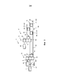
на Фиг. 2 показан схематичный вид сбоку коробки переключения передач согласно настоящему изобретению;in FIG. 2 is a schematic side view of a gearbox according to the present invention;
на Фиг. 3 показан схематичный вид сбоку коробки переключения передач согласно настоящему изобретению; иin FIG. 3 is a schematic side view of a gearbox according to the present invention; and
на Фиг. 4 показана блок-схема способа управления коробкой переключения передач согласно настоящему изобретению.in FIG. 4 is a flowchart of a method for controlling a gearbox according to the present invention.
Подробное описание вариантов осуществления настоящего изобретенияDetailed Description of Embodiments of the Present Invention
На Фиг. 1 схематично показан вид сбоку транспортного средства 1, которое содержит коробку 2 переключения передач согласно настоящему изобретению. Двигатель 4 внутреннего сгорания соединен с коробкой 2 переключения передач, и коробка 2 переключения передач далее соединена с ведущими колесами 6 транспортного средства 1.In FIG. 1 is a schematic side view of a vehicle 1, which comprises a
На Фиг. 2 показан схематичный вид сбоку коробки 2 переключения передач согласно настоящему изобретению. Коробка 2 переключения передач содержит входной вал 8, первую и вторую эпициклические передачи 10 и 12, первую и вторую электрические машины 14 и 16, боковой вал 18 и выходной вал 20. Первая эпициклическая передача 10 имеет первое кольцевое зубчатое колесо 22, с которым соединен первый ротор 24 первой электрической машины 14. Первая эпициклическая передача 10 также имеет первое солнечное зубчатое колесо 26. Вторая эпициклическая передача 12 имеет второе кольцевое зубчатое колесо 28, с которым соединен второй ротор 30 второй электрической машины 16. Вторая эпициклическая передача 12 имеет второе солнечное зубчатое колесо 32. Первое и второе солнечные зубчатые колеса 26 и 32 расположены соосно, в результате чего, согласно показанной конструкции, первый основной вал 34, расположенный у первого солнечного зубчатого колеса 26, проходит внутри второго основного вала 36, расположенного у второго солнечного зубчатого колеса 32, причем этот второй основной вал 36 предусмотрен с центральным отверстием 38. Также возможно расположить первый основной вал 34 параллельно второму основному валу 36 или сбоку от него.In FIG. 2 is a schematic side view of a
Первая электрическая машина 14 предусмотрена с первым статором 40, который соединен с транспортным средством 1 через корпус 42 коробки переключения передач, который окружает коробку 2 переключения передач. Вторая электрическая машина 16 предусмотрена со вторым статором 44, который соединен с транспортным средством 1 через корпус 42 коробки переключения передач, который окружает коробку 2 переключения передач. Первая 14 и вторая электрические машины 16 соединены с накопителем 46 энергии, таким как батарея, который приводит электрические машины 14 и 16 в зависимости от режима работы транспортного средства 1. В других режимах работы, электрические машины 14 и 16 могут выполнять функцию генераторов, посредством которых ток подается к накопителю 46 энергии. Электронный управляющий блок 48 соединен с накопителем 46 энергии и управляет подачей тока к электрическим машинам 14 и 16. Предпочтительно, чтобы накопитель 46 энергии был соединен с электрическими машинами 14 и 16 через переключатель 49, который соединен с управляющим блоком 48. В некоторых режимах работы электрические машины 14 и 16 также могут приводить друг друга. Тогда электрическая энергия проводится от одной электрической машины 14, 16 к другой электрической машине 14, 16 через переключатель 49, который соединен с электрическими машинами 14, 16. Таким образом, возможно достигать баланса мощности между электрическими машинами 14, 16. Другой компьютер 53 может быть соединен с управляющим блоком 48 и с коробкой 2 переключения передач. Посредством проведения электрической энергии от одной электрической машины 14, 16 к другой электрической машине 14, 16 через переключатель 49, электрическая энергия не проводится к накопителю 46 энергии и от него. Таким образом, обеспечиваются условия, требуемые для увеличения срока службы накопителя 46 энергии. Таким образом, также возможно выполнять переключения передач и приводить транспортное средство 1 в движение без накопителя 46 энергии.The first
Первая эпициклическая передача 10 предусмотрена с первым водилом 50 планетарной передачи, на котором на подшипниках установлен первый набор 52 планетарных зубчатых колес. Вторая эпициклическая передача 12 предусмотрена со вторым водилом 51 планетарной передачи, на котором на подшипниках установлен второй набор 54 планетарных зубчатых колес. Первый набор 52 планетарных зубчатых колес взаимодействует с первым кольцевым зубчатым колесом 22 и с первым солнечным зубчатым колесом 26. Второй набор 54 планетарных зубчатых колес взаимодействует со вторым кольцевым зубчатым колесом 28 и со вторым солнечным зубчатым колесом 32. Входной вал 8 коробки 2 переключения передач соединен с первым водилом 50 планетарной передачи. Первое водило 50 планетарной передачи в первой эпициклической передаче 10 непосредственно и неподвижно соединено со вторым солнечным зубчатым колесом 32 во второй эпициклической передаче 12. Таким образом, первое водило 50 планетарной передачи и второе солнечное зубчатое колесо 32 всегда имеют одинаковое направление вращения и одинаковую скорость вращения.The first
Первый соединительный узел 56 расположен между первым солнечным зубчатым колесом 26 и первым водилом 50 планетарной передачи. Посредством расположения первого соединительного узла 56 таким образом, чтобы первое солнечное зубчатое колесо 26 и первое водило 50 планетарной передачи были соединены друг с другом и, таким образом, не могли вращаться относительно друг друга, первое водило 50 планетарной передачи и первое солнечное зубчатое колесо 26 вращаются с одинаковыми скоростями вращения.A
Второй соединительный узел 58 расположен между вторым солнечным зубчатым колесом 32 и вторым водилом 51 планетарной передачи. Посредством расположения второго соединительного узла 58 так, чтобы второе солнечное зубчатое колесо 32 и второе водило 51 планетарной передачи были соединены друг с другом и, таким образом, не могли вращаться относительно друг друга, второе водило 51 планетарной передачи и второе солнечное зубчатое колесо 32 вращаются с равными скоростями вращения.The second connecting
Первый и второй соединительные узлы 56, 58 предпочтительно содержат первую и вторую соединительные муфты 55 и 57, оснащенные шлицами, которые могут быть смещены в осевом направлении по оснащенной шлицами секции с первым и вторым водилами 50 и 51 планетарной передачи и по оснащенной шлицами секции с соответствующими солнечными зубчатыми колесами 26 и 32. Посредством смещения соответствующей соединительной муфты 55, 57 так, чтобы оснащенные шлицами секции были соединены через соответствующую соединительную муфту 55, 57, первое водило 50 планетарной передачи и первое солнечное зубчатое колесо 26, и второе водило 51 планетарной передачи и второе солнечное зубчатое колесо 32 становятся взаимно блокированными друг с другом, и не могут вращаться относительно друг друга.The first and
Первый и второй соединительные узлы 56, 58 согласно конструкции, показанной на Фиг.2, расположены между первым солнечным зубчатым колесом 26 и первым водилом 50 планетарной передачи и между вторым солнечным зубчатым колесом 32 и вторым водилом 51 планетарной передачи, соответственно. Тем не менее, возможно располагать дополнительный или альтернативный соединительный узел (не показан на чертежах) между первым кольцевым зубчатым колесом 22 и первым водилом 50 планетарной передачи, а также располагать дополнительный или альтернативный соединительный узел (не показан на чертежах) между вторым кольцевым зубчатым колесом 28 и вторым водилом 51 планетарной передачи.The first and second connecting
Третий соединительный узел 59 в этом варианте осуществления расположен между первым кольцевым зубчатым колесом 22 и корпусом 42 коробки переключения передач. Посредством расположения третьего соединительного узла 59 так, чтобы первое кольцевое зубчатое колесо 22 и корпус 42 коробки переключения передач были соединены друг с другом и, таким образом, не могли вращаться относительно друг друга, происходит понижение крутящего момента, то есть, происходит повышение скорости вращения от водила 50 планетарной передачи к первому солнечному зубчатому колесу 26.A third connection unit 59 in this embodiment is located between the
Четвертый соединительный узел 61 в этом варианте осуществления расположен между вторым кольцевым зубчатым колесом 28 и корпусом 42 коробки переключения передач. Посредством расположения четвертого соединительного узла 61 так, чтобы второе кольцевое зубчатое колесо 28 и корпус 42 коробки переключения передач были соединены друг с другом и, таким образом, не могли вращаться относительно друг друга, происходит понижение крутящего момента, то есть, происходит повышение скорости вращения от водила 50 планетарной передачи ко второму солнечному зубчатому колесу 32.A fourth coupling unit 61 in this embodiment is located between the
Третий и четвертый соединительные узлы 59, 61 содержат третью и четвертую соединительные муфты 65 и 67, оснащенные шлицами, которые могут быть смещены в осевом направлении по оснащенной шлицами секции с первым и вторым кольцевыми зубчатыми колесами 22 и 28 и по оснащенной шлицами секции с корпусом 42 коробки переключения передач. Посредством смещения соответствующей соединительной муфты 65, 67 так, чтобы оснащенные шлицами секции были соединены через соответствующую соединительную муфту 65, 67, первое кольцевое зубчатое колесо 22 и корпус 42 коробки переключения передач, и второе кольцевое зубчатое колесо 28 и корпус 42 коробки переключения передач, становятся взаимно блокированными друг с другом, и не могут вращаться относительно друг друга.The third and fourth coupling units 59, 61 comprise a third and
Механизм 19 коробки передач соединен с первым и вторым основными валами 34, 36, причем этот механизм коробки передач содержит первую зубчатую пару 60, которая расположена между первой эпициклической передачей 10 и выходным валом 20. Первая зубчатая пара 60 содержит первое ведущее зубчатое колесо 62 и первое зубчатое колесо 64, которые взаимодействуют друг с другом. Вторая зубчатая пара 66 расположена между второй эпициклической передачей 12 и выходным валом 20. Вторая зубчатая пара 66 содержит второе ведущее зубчатое колесо 68 и второе зубчатое колесо 70, которые взаимодействуют друг с другом. Третья зубчатая пара 72 расположена между первой эпициклической передачей 10 и выходным валом 20. Третья зубчатая пара 72 содержит третье ведущее зубчатое колесо 74 и третье зубчатое колесо 76, которые взаимодействуют друг с другом. Четвертая зубчатая пара 78 расположена между второй эпициклической передачей 12 и выходным валом 20. Четвертая зубчатая пара 78 содержит четвертое ведущее зубчатое колесо 80 и четвертое зубчатое колесо 82, которые взаимодействуют друг с другом.The
Первое и третье ведущие зубчатые колеса 62 и 74 расположены на первом основном вале 34. Первое и третье ведущие зубчатые колеса 62 и 74 неподвижно соединены с первым основным валом 34 так, что они не могут вращаться относительно первого основного вала 34. Второе и четвертое ведущие зубчатые колеса 68 и 80 расположены на втором основном вале 36. Второе и четвертое ведущие зубчатые колеса 68 и 80 неподвижно соединены со вторым основным валом 36, так чтобы они не могли вращаться относительно второго основного вала 36.The first and third drive gears 62 and 74 are located on the first
Боковой вал 18 проходит, по существу, параллельно первому и второму основным валам 34 и 36. Первое, второе, третье и четвертое зубчатые колеса 64, 70, 76 и 82 расположены на подшипниках на боковом вале 18. Первое ведущее зубчатое колесо 62 взаимодействует с первым зубчатым колесом 64, второе ведущее зубчатое колесо 68 взаимодействует со вторым зубчатым колесом 70, третье ведущее зубчатое колесо 74 взаимодействует с третьим зубчатым колесом 76 и четвертое ведущее зубчатое колесо 80 взаимодействует с четвертым зубчатым колесом 82.The
Первое, второе, третье и четвертое зубчатые колеса 64, 70, 76 и 82 могут быть индивидуально сцеплены с блокировкой и расцеплены с боковым валом 18 с помощью первого, второго, третьего и четвертого соединительных элементов 84, 86, 88 и 90. Соединительные элементы 84, 86, 88 и 90 предпочтительно составлены из секций, оснащенных шлицами, выполненных у зубчатых колес 64, 70, 76 и 82 и бокового вала 18, которые взаимодействуют с пятой и шестой соединительными муфтами 83, 85, которые механически взаимодействуют с секциями, оснащенными шлицами у зубчатых колес с первого по четвертое 64, 70, 76 и 82, соответственно, и с боковым валом 18. Первый и третий соединительные элементы 84, 88 предпочтительно предусмотрены с общей соединительной муфтой 83, и второй и четвертый соединительные элементы 86, 90 предпочтительно предусмотрены с общей соединительной муфтой 85. В расцепленном состоянии между зубчатыми колесами 64, 70, 76 и 82 и боковым валом 18 может возникать относительное вращение. Соединительные элементы 84, 86, 88 и 90 также могут быть составлены из фрикционных соединителей. На боковом вале 18 также расположено пятое зубчатое колесо 92, которое взаимодействует шестым зубчатым колесом 94, которое расположено на выходном вале 20 коробки 2 переключения передач.The first, second, third, and
Боковой вал 18 расположен между соответствующей первой или второй эпициклической передачей 10, 12 и выходным валом 20, так чтобы боковой вал 18 был соединен с выходным валом 20 через конечную передачу или пятую зубчатую пару 21, которая содержит пятое и шестое зубчатые колеса 92, 94. Пятое зубчатое колесо расположено на боковом вале 18 посредством пятого соединительного элемента 93 с возможностью его зацепления и расцепления.The
Посредством расцепления пятого зубчатого колеса 92, которое расположено на боковом вале 18 с возможностью его расцепления, обеспечивается возможность передачи крутящего момента со второй эпициклической передачи 12 на боковой вал 18 через вторую зубчатую пару 66 и передачи крутящего момента далее с бокового вала 18 на выходной вал 20 через первую зубчатую пару 60. Таким образом, достигается некоторое количество зубчатых переборов, причем крутящий момент с одной из эпициклических передач 10, 12 может быть передан к боковому валу 18 и далее с бокового вала 18 к основному валу 34, 36, который соединен с другой эпициклической передачей 10, 12, для того, чтобы, в итоге, передавать крутящий момент к выходному валу 20 коробки переключения передач. Тем не менее, для этого необходимо, чтобы соединительный механизм 96, расположенный между первым основным валом 34 и выходным валом 20 был зацеплен, что более подробно описано ниже.By disengaging the
Пятое зубчатое колесо 92 может быть блокировано с боковым валом 18 и отцеплено от него с помощью пятого соединительного элемента 93. Соединительный элемент 93 предпочтительно составлен секциями, которые оснащены шлицами, выполненными на пятом зубчатом колесе 92 и на боковом вале 18, причем эти секции взаимодействуют с девятой соединительной муфтой 87, которая механически взаимодействует с секциями, которые оснащены шлицами, на пятом зубчатом колесе 92 и боковом вале 18. В расцепленном состоянии между пятым зубчатым колесом 92 и боковым валом 18 может возникать относительное вращение. Пятый соединительный элемент 93 также может быть составлен фрикционными соединителями.The
Во время некоторых операций переключения передач, когда эпициклические зубчатые колеса эпициклических передач 10, 12 неподвижно блокированы с корпусом 42 коробки переключения передач с помощью третьего и четвертого соединительных узлов 59, 61, крутящий момент понижается после первой эпициклической передачи 10 и повышается после второй эпициклической передачи 12. Если передача крутящего момента по первому основному валу 34 через боковой вал 18 уменьшается после первой эпициклической передачи 10, то валы, зубчатые приводы и зубчатые колеса, которые соединены с ним, могут быть выполнены с меньшими размерами, что делает коробку 2 переключения передач более компактной. Также большое количество зубчатых переборов может быть достигнуто без необходимости расположения множества дополнительных зубчатых пар в коробке переключения передач. Таким образом, также уменьшаются вес и стоимость коробки 2 переключения передач. Пятое и шестое зубчатые колеса 92 и 94 выполняют функцию пятой зубчатой пары 21, которая передает крутящий момент выходному валу 20 коробки 2 переключения передач.During some gear shifting operations, when the epicyclic gears of the epicyclic gears 10, 12 are fixedly locked to the
Передача крутящего момента от входного вала 8 коробки 2 переключения передач к выходному валу 20 коробки 2 переключения передач происходит через либо первую 10, либо вторую эпициклическую передачу 12 и боковой вал 18. Передача крутящего момента также может происходить непосредственно через первую эпициклическую передачу 10, первое солнечное зубчатое колесо 26 которой через первый основной вал 34 соединено с выходным валом 20 коробки 2 переключения передач через соединительный механизм 96. Соединительный механизм 96 предпочтительно содержит седьмую соединительную муфту 100, оснащенную шлицами, причем эта соединительная муфта может быть смещена в осевом направлении по первому основному валу 34 и по секциям выходного вала 20, которые оснащены шлицами. Посредством смещения седьмой соединительной муфты 100 так, чтобы секции, которые оснащены шлицами, были соединены через седьмую соединительную муфту 100, первый основной вал 34 становится неподвижно блокированным с выходным валом 20, и, таким образом, они имеют одинаковую скорость вращения. Посредством отцепления пятого зубчатого колеса 92 пятой зубчатой пары 21 от бокового вала 18, крутящий момент от второй эпициклической передачи 12 может быть передан к боковому валу 18 и далее от бокового вала 18 к основному валу 34, который соединен с первой эпициклической передачей 10, для того, чтобы, в итоге, передавать крутящий момент к выходному валу 20 коробки 2 переключения передач через соединительный механизм 96.The transmission of torque from the
Во время работы, коробка 2 переключения передач может работать в определенных режимах работы, например, когда одно из солнечных зубчатых колес 26 или 32 блокировано с первым или вторым водилом 50 или 51 планетарной передачи с помощью первого или второго соединительного узла 56 или 58. Тогда первому или второму основному валу 34 или 36 придается такая же скорость вращения, как у входного вала 8 коробки 2 переключения передач, в зависимости от того какое солнечное зубчатое колесо 26 или 32 блокировано с соответствующим водилом 50 или 51 планетарной передачи. Одна или обе электрические машины 14 и 16 могут выполнять функцию генератора для образования электрической энергии для накопителя 46 энергии. В качестве альтернативы, электрическая машина 14 или 16 может обеспечивать увеличение крутящего момента для того, чтобы, таким образом, увеличивать крутящий момент на выходном вале 20. В некоторых режимах работы электрические машины 14 и 16 обеспечивают друг друга электрической энергией, независимо от накопителя 46 энергии.During operation, the
К тому же, в некоторых режимах работы, коробка 2 переключения передач может функционировать так, чтобы один из роторов 24 и 30 электрических машин 14 и 16 был неподвижно блокирован с корпусом 42 коробки переключения передач через кольцевые зубчатые колеса 22 и 28, в то время как вторая электрическая машина 14 и 16 выполняет функцию генератора для выработки электрической энергии для накопителя 46 энергии, что более подробно описано далее. Электрическая машина 14 или 16, ротор 24 или 30 которой неподвижно блокирован с корпусом 42 коробки переключения передач, поглощает реактивный крутящий момент от кольцевого зубчатого колеса 22 или 28, перед выполнением блокировки с помощью третьего или четвертого соединительного узла 59 или 61. Вместо выполнения функции генератора, электрическая машина 14 или 16 может обеспечивать увеличение крутящего момента для того, чтобы, таким образом, увеличивать крутящий момент у выходного вала 20.In addition, in some operating modes, the
Как первая, так и вторая электрические машины 14 и 16 также могут одновременно вырабатывать ток для накопителя 46 энергии. Во время торможения двигателя водитель отпускает педаль акселератора (не показана на чертежах) транспортного средства 1. Затем выходной вал 20 коробки 2 переключения передач приводит либо одну, либо обе электрические машины 14 и 16, в то время как двигатель 4 внутреннего сгорания и электрические машины 14 и 16 одновременно обеспечивают торможение двигателя. В этом случае, электрические машины 14 и 16 вырабатывают электрическую энергию, которая хранится в накопителе 46 энергии в транспортном средстве 1. Этот режим работы известен как "регенеративное торможение". Для того, чтобы сделать возможным более мощный эффект торможения, выходной вал 97 двигателя 4 внутреннего сгорания может быть неподвижно блокирован, и, таким образом, его вращение может быть предотвращено. Таким образом, только одна или обе электрические машины 14 и 16 выполняют функцию тормоза и вырабатывают электрическую энергию, которая хранится в накопителе 46 энергии. Блокировка выходного вала 97 двигателя 4 внутреннего сгорания также может быть выполнена, когда транспортное средство разгоняется посредством только одной или обеих электрических машин 14 и 16. Если крутящий момент одной или обеих электрических машин 14 и 16 превышает крутящий момент двигателя 4 внутреннего сгорания, учитывая передаточное отношение между ними, двигатель 4 внутреннего сгорания не может выдерживать большой крутящий момент, который производят электрические машины 14 и 16, и поэтому необходимо неподвижно блокировать выходной вал 97 двигателя 4 внутреннего сгорания. Блокировка выходного вала 97 двигателя 4 внутреннего сгорания предпочтительно выполняется посредством блокирующего устройства 102, которое расположено между первым водилом 50 планетарной передачи и корпусом 42 коробки переключения передач. Посредством блокировки первого водила 50 планетарной передачи и корпуса 42 коробки переключения передач, блокируется также выходной вал 97 двигателя 4 внутреннего сгорания, поскольку выходной вал 97 двигателя 4 внутреннего сгорания соединен с первым водилом 50 планетарной передачи через входной вал 8 коробки переключения передач. Блокирующее устройство 102 предпочтительно содержит восьмую соединительную муфту 104, оснащенную шлицами, которая может быть смещена в осевом направлении по оснащенной шлицами секции первого водила 50 планетарной передачи и по оснащенной шлицами секции корпуса коробки переключения передач. Посредством смещения восьмой соединительной муфты 104 так, чтобы секции, которые оснащены шлицами, были соединены через соединительную муфту 104, предотвращается вращение первого водила 50 планетарной передачи и, таким образом, также выходного вала 97 двигателя 4 внутреннего сгорания.Both the first and second
Управляющий блок 48 соединен с электрическими машинами 14 и 16 и выполнен с возможностью управления электрическими машинами 14 и 16 так, чтобы при некоторых подходящих режимах работы они использовали накопленную электрическую энергию для приложения движущей силы к выходному валу 20 коробки 2 переключения передач, и так, чтобы при других режимах работы они использовали кинетическую энергию выходного вала 20 коробки 2 переключения передач для выработки и накопления электрической энергии. Таким образом, управляющий блок 48 определяет по меньшей мере либо скорость вращения, либо крутящий момент выходного вала 97 двигателя 4 внутреннего сгорания посредством датчиков 98, расположенных у электрических машин 14 и 16 и у выходного вала 20 коробки 2 переключения передач, для того чтобы, таким образом, собирать информацию и управлять электрическими машинами 14 и 16 так, чтобы они выполняли функцию электродвигателей или генераторов. Управляющий блок 48 может представлять собой компьютер с программным обеспечением, подходящим для этой цели. Управляющий блок 48 также управляет током электрической энергии между накопителем 46 энергии и соответствующим статором 40 и 44 в электрических машинах 14 и 16. В условиях, в которых электрические машины 14 и 16 выполняют функцию двигателей, накопленная электрическая энергия подается от накопителей 46 энергии к соответствующему статору 40 и 44. В условиях, в которых электрические машины 14 и 16 выполняют функцию генераторов, электрическая энергия подается от соответствующего статора 40 и 44 к накопителю 46 энергии. Тем не менее, как упомянуто выше, в некоторых режимах работы электрические машины 14 и 16 могут обеспечивать электрической энергией друг друга, независимо от накопителя 46 энергии.The
Первый, второй, третий и четвертый соединительные узлы 56, 58, 59 и 61, первый, второй, третий, четвертый и пятый соединительные элементы 84, 86, 88, 90 и 93, соединительный механизм 96 между первым основным валом 34 и выходным валом 20, и блокирующее устройство 102 между первым водилом 50 планетарной передачи и корпусом 42 коробки переключения передач соединены с управляющим блоком 48 через соответствующие соединительные муфты. Эти компоненты предпочтительно включаются и выключаются посредством электрических сигналов от управляющего блока 48. Соединительные муфты предпочтительно смещаются посредством источников силы, не показанных на чертежах, таких как гидравлические или пневматические цилиндры. Также соединительные муфты могут смещаться посредством электрических источников силы.The first, second, third and fourth connecting
Согласно варианту осуществления на Фиг.2, четыре ведущих зубчатых колеса 62, 68, 74 и 80 и четыре зубчатых колеса 64, 70, 76 и 82 показаны вместе с двумя эпициклическими передачами 10 и 12 с их соответствующими электрическими машинами 14 и 16. Тем не менее, возможно разработать коробку 2 переключения передач с большим или меньшим количеством ведущих зубчатых колес и зубчатых колес и с большим количеством планетарных передач с их соответствующими электрическими машинами.According to the embodiment of FIG. 2, four
На Фиг.3 проиллюстрирована линия 3 гибридной тяги согласно Фиг.2 в упрощенном схематичном виде, на котором некоторые компоненты опущены для ясности. На Фиг.3 показана зубчатая пара G1, соединенная с первым основным валом 34 и, таким образом, также с первой эпициклической передачей 10, и зубчатая пара G2, соединенная со вторым основным валом 36 и, таким образом, также со второй эпициклической передачей 12. Эти зубчатые пары G1, G2 также соединены с выходным валом 20 через боковой вал 18. Зубчатая пара G1, которая соединена с первым основным валом 34, может быть составлена, например, первой зубчатой парой 60 или третьей зубчатой парой 72, как описано на Фиг. 2 и 3, а также она может содержать дополнительные зубчатые пары. Зубчатая пара G2, которая соединена со вторым основным валом 36, может быть составлена, например, второй зубчатой парой 66 или четвертой зубчатой парой 78, как описано на Фиг. 2 и 3, а также она может содержать дополнительные зубчатые пары. К тому же, показана пятая зубчатая пара G3, 21, которая соединена с выходным валом 20 и боковым валом 18 и которая также описана на Фиг. 2 и 3. Тем не менее, G3 может быть составлена дополнительными зубчатыми парами. При переключении передачи выбирается подходящая зубчатая пара из соответствующей группы G1, G2, G3.FIG. 3 illustrates the
По меньшей мере одна зубчатая пара G1, 60, 72, которая соединена с первой эпициклической передачей 10, содержит по меньшей мере одно ведущее зубчатое колесо 62, 74 и зубчатое колесо 64, 76, расположенные с возможностью взаимодействия друг с другом, причем это ведущее зубчатое колесо 62, 74 может быть расположено так, чтобы оно могло быть зацеплено и расцеплено с первым основным валом 34, предусмотренным с первой эпициклической передачей 10. По меньшей мере одно зубчатое колесо 64, 76 может быть расположено так, чтобы оно могло быть зацеплено и расцеплено с боковым валом 18.At least one gear pair G1, 60, 72, which is connected to the first
По меньшей мере одна зубчатая пара G2, 66, 78, которая соединена со второй эпициклической передачей 12, содержит по меньшей мере одно ведущее зубчатое колесо 68, 80 и зубчатое колесо 70, 82, расположенные с возможностью взаимодействия друг с другом, причем это ведущее зубчатое колесо 68, 80 может быть расположено так, чтобы оно могло быть зацеплено и расцеплено со вторым основным валом 36, предусмотренным со второй эпициклической передачей 12. По меньшей мере одно зубчатое колесо 70, 82 может быть расположено так, чтобы оно могло быть зацеплено и расцеплено с боковым валом 18.At least one gear pair G2, 66, 78, which is connected to the second
Далее описано повышение с первой на наивысшую передачу, когда коробка 2 переключения передач установлена в транспортном средстве 1. Входной вал 8 коробки 2 переключения передач соединен с выходным валом 97 двигателя 4 внутреннего сгорания транспортного средства 1. Выходной вал 20 коробки 2 переключения передач соединен с ведущим валом 99 транспортного средства 1. Во время холостой работы двигателя 4 внутреннего сгорания и когда транспортное средство 1 не движется, входной вал 8 коробки 2 переключения передач вращается, в то время как выходной вал 20 коробки 2 переключения передач остается неподвижным. Блокирующее устройство 102 выключено, так что выходной вал 97 двигателя 4 внутреннего сгорания может свободно вращаться. Поскольку входной вал 8 коробки 2 переключения передач вращается, первое водило 50 планетарной передачи также вращается, в результате чего вращается первый набор 52 планетарных зубчатых колес. Поскольку первое водило 50 планетарной передачи соединено со вторым солнечным зубчатым колесом 32, второе солнечное зубчатое колесо 32, а также второй набор 54 планетарных зубчатых колес вращаются. Посредством отсутствия подачи тока к первой и второй электрическим машинам 14 и 16 и отсутствия извлечения тока из них, первое и второе кольцевые зубчатые колеса 22 и 28, которые соединены с первым и вторым роторами 24 и 30, соответственно, у соответствующей электрической машины 14 и 16, вращаются свободно, посредством чего никакой крутящий момент не поглощается кольцевыми зубчатыми колесами 22 и 28. Первый, второй, третий и четвертый соединительные узлы 56, 58, 59 и 61 расцеплены и, таким образом, не включены. Таким образом, никакой крутящий момент не передается от двигателя 4 внутреннего сгорания к солнечным зубчатым колесам 26 и 32 эпициклических передач 10 и 12. Соединительный механизм 96 между первым основным валом 34 и выходным валом 20 расцеплен, так что первый основной вал 34 и выходной вал 20 могут свободно вращаться относительно друг друга. Поскольку солнечные зубчатые колеса 26 и 32 и выходной вал 20 коробки 2 переключения передач в этой фазе являются неподвижными, боковой вал 18 также является неподвижным. На первом этапе четвертое зубчатое колесо 82 и третье зубчатое колесо 76 соединены с боковым валом 18 с помощью четвертого и третьего соединительных элементов 90 и 88. Первое зубчатое колесо 64 и второе зубчатое колесо 70 отцеплены от бокового вала 18. Таким образом, первое зубчатое колесо 64 и второе зубчатое колесо 70 могут свободно вращаться относительно бокового вала 18. Пятое зубчатое колесо 92 пятой зубчатой пары 21 неподвижно блокировано с боковым валом 18 с помощью пятого соединительного элемента 93.The following describes the increase from first to highest gear when the
Для того, чтобы начать вращение выходного вала 20 коробки 2 переключения передач с целью приведения транспортного средства 1, четвертое ведущее зубчатое колесо 80 и четвертое зубчатое колесо 82 на боковом вале 18 приводятся во вращение. Это достигается посредством приведения во вращение второго водила 51 планетарной передачи. Когда второе водило планетарной передачи вращается, второй основной вал 36 также вращается, и, таким образом, также вращается четвертое ведущее зубчатое колесо 80, которое расположено на втором основном вале 36. Второе водило 51 планетарной передачи приводится во вращение через второе кольцевое зубчатое колесо 28, управляемое второй электрической машиной 16. Посредством включения второй электрической машины 16 и управления двигателем 4 внутреннего сгорания до достижения подходящей скорости вращения, транспортное средство 1 начинает смещаться посредством начала вращения второго основного вала 36. Когда второе водило 51 планетарной передачи и второе солнечное зубчатое колесо 32 достигают одинаковой скорости вращения, второе солнечное зубчатое колесо 32 неподвижно блокируется со вторым водилом 51 планетарной передачи с помощью второго соединительного узла 58. Как упомянуто выше, второй соединительный узел 58 предпочтительно выполнен так, чтобы второе солнечное зубчатое колесо 32 и второе водило 51 планетарной передачи находились в механическом взаимодействии друг с другом. В качестве альтернативы, второй соединительный узел 58 может быть выполнен как скользящий тормоз или пластинчатое сцепление, которое плавно соединяет второе солнечное зубчатое колесо 32 со вторым водилом 51 планетарной передачи. Когда второе солнечное зубчатое колесо 32 соединено со вторым водилом 51 планетарной передачи, второе солнечное зубчатое колесо 32 вращается с такой же скоростью вращения, как выходной вал 97 двигателя 4 внутреннего сгорания. Таким образом, крутящий момент, производимый двигателем 4 внутреннего сгорания, передается к выходному валу 20 коробки 2 переключения передач через четвертое ведущее зубчатое колесо 80, четвертое зубчатое колесо 82 на боковом вале 18, пятое зубчатое колесо 92 на боковом вале 18 и шестое зубчатое колесо 94 на выходном вале 20 коробки 2 переключения передач. Таким образом, транспортное средство 1 начинает двигаться и приводится вперед на первой передаче.In order to start the rotation of the
Каждая из первой, второй, третьей и четвертой зубчатых пар 60, 66, 72, 78 имеет передаточное отношение, которое приспособлено к требуемым ходовым характеристикам транспортного средства 1. Согласно варианту осуществления, показанному на Фиг.2, четвертая зубчатая пара 78 имеет наивысшее передаточное отношение по сравнению с первой, второй и третьей зубчатыми парами 60, 66, 72, что означает, что четвертая зубчатая пара 78 соединяется, когда выбирается самая низшая передача. Вторая зубчатая пара 66, как и четвертая зубчатая пара 78, передает крутящий момент между вторым основным валом 36 и боковым валом 18, и в качестве альтернативы возможно разработать ее с наивысшим передаточным отношением по сравнению с другими зубчатыми парами 60, 72, 78, вследствие чего в такой конструкции вторая зубчатая пара 66 соединяется при выборе самой низшей передачи.Each of the first, second, third and fourth gear pairs 60, 66, 72, 78 has a gear ratio that is adapted to the required driving characteristics of the vehicle 1. According to the embodiment shown in FIG. 2, the
Когда боковой вал 18 приводится во вращение четвертым зубчатым колесом 82 на боковом вале 18, третье зубчатое колесо 76 на боковом вале 18 также вращается. Таким образом, боковой вал 18 приводит третье зубчатое колесо 76, которое в свою очередь приводит третье ведущее зубчатое колесо 74 на первом основном вале 34. Когда первый основной вал 34 вращается, первое солнечное зубчатое колесо 26 также вращается, что, таким образом, в зависимости от скорости вращения выходного вала 97 двигателя 4 внутреннего сгорания и, следовательно, также от скорости вращения первого водила 50 планетарной передачи, приводит во вращение первое кольцевое зубчатое колесо 22 и первый ротор 24 первой электрической машины 14. В этом случае, возможно позволить первой электрической машине 14 выполнять функцию генератора для подачи тока по меньшей мере к одному накопителю 46 энергии и ко второй электрической машине 16. Вторая электрическая машина 16 также может быть приведена в качестве генератора. В качестве альтернативы, первая электрическая машина 14 может обеспечивать дополнительный крутящий момент через управляющий блок 48, управляющий первой электрической машиной 14, для обеспечения движущего крутящего момента.When the
Для переключения передачи с первой передачи на вторую передачу, блокировка между вторым солнечным зубчатым колесом 32 и вторым водилом 51 планетарной передачи должна быть расцеплена, что достигается посредством управления по меньшей мере одной из первой и второй электрических машин 14, 16 так, чтобы равновесие крутящих моментов преобладало во второй эпициклической передаче 12. После этого второй соединительный узел 58 управляется так, чтобы он отцеплял второе солнечное зубчатое колесо 32 и второе водило 51 планетарной передачи друг от друга. Второе водило 51 планетарной передачи и второй основной вал 36 могут вращаться свободно, в результате чего второе солнечное зубчатое колесо 32, второе водило 51 планетарной передачи и второй основной вал 36 больше не приводят четвертое ведущее зубчатое колесо 80, которое расположено на втором основном вале 36. Для этого вторая электрическая машина 16 не должна приводить второе кольцевое зубчатое колесо 28. Вторая передача выбирается посредством управляющего блока 48, управляющего первой электрической машиной 14, чтобы синхронная скорость вращения возникала между первым водилом 50 планетарной передачи и первым солнечным зубчатым колесом 26, для достижения блокировки между первым водилом 50 планетарной передачи и первым солнечным зубчатым колесом 26. Это достигается через управление первым соединительным узлом 56 так, чтобы первое водило 50 планетарной передачи и первое солнечное зубчатое колесо 26 были механически соединены друг с другом. В качестве альтернативы, первый соединительный узел 56 может быть выполнен как скользящий тормоз или пластинчатое сцепление, которое плавно соединяет первое солнечное зубчатое колесо 26 и первое водило 50 планетарной передачи. Посредством синхронизации управления двигателем 4 внутреннего сгорания и первой и второй электрическими машинами 14 и 16, возможно выполнять мягкий и непрерывный переход с первой передачи на вторую передачу.To change gear from first gear to second gear, the interlock between the
Теперь первый основной вал 34 вращается и приводится выходным валом 97 двигателя 4 внутреннего сгорания, и первый основной вал 34 теперь приводит третье ведущее зубчатое колесо 74. Первое водило 50 планетарной передачи теперь приводит третье ведущее зубчатое колесо 74 через первое солнечное зубчатое колесо 26 и первый основной вал 34. Поскольку третье зубчатое колесо 76 взаимодействует с третьим ведущим зубчатым колесом 74 и неподвижно соединено с боковым валом 18, третье зубчатое колесо 76 приводит боковой вал 18, который в свою очередь приводит пятое зубчатое колесо 92 на боковом вале 18. Пятое зубчатое колесо 92 в свою очередь приводит выходной вал 20 коробки 2 переключения передач через шестое зубчатое колесо 94, которое расположено на выходном вале 20 коробки 2 переключения передач. Теперь транспортное средство 1 движется на второй передаче.Now, the first
Когда боковой вал 18 приводится во вращение третьим зубчатым колесом 76, четвертое зубчатое колесо 82 также вращается. Таким образом, боковой вал 18 приводит четвертое зубчатое колесо 82, которое в свою очередь приводит четвертое ведущее зубчатое колесо 80 на втором основном вале 36. Когда второй основной вал 36 вращается, второе водило 51 планетарной передачи также вращается, что, таким образом, в зависимости от скорости вращения выходного вала 97 двигателя 4 внутреннего сгорания и, следовательно, также от скорости вращения первого водила 50 планетарной передачи, приводит во вращение второе кольцевое зубчатое колесо 28 и второй ротор 30 второй электрической машины 16. В этом случае, можно позволить второй электрической машине 16 выполнять функцию генератора для подачи тока по меньшей мере к одному накопителю 46 энергии и к первой электрической машине 14. Вторая электрическая машина 16 также может обеспечивать дополнительный крутящий момент через управляющий блок 48, управляющий второй электрической машиной 16, для обеспечения движущего крутящего момента.When the
Для переключения передачи со второй передачи на третью передачу, четвертое зубчатое колесо 82 на боковом вале 18 должно быть отцеплено от бокового вала 18 с помощью четвертого соединительного элемента 90, чтобы четвертое зубчатое колесо 82 могло свободно вращаться относительно бокового вала 18. После этого боковой вал 18 соединяется со вторым зубчатым колесом 70 на боковом вале 18 через второй соединительный элемент 86. Для достижения соединения бокового вала 18 и второго зубчатого колеса 70 на боковом вале 18, вторая электрическая машина 16 предпочтительно управляется так, чтобы синхронная скорость вращения возникала между боковым валом 18 и вторым зубчатым колесом 70 на боковом вале 18. Синхронная скорость вращения может быть определена через измерение скорости вращения второго ротора 30 второй электрической машины 16 и через измерение скорости вращения выходного вала 20. Таким образом, скорость вращения второго основного вала 36 и скорость вращения бокового вала 18 могут быть определены через данное передаточное число. Скорости вращения соответствующих валов 18 и 36 управляются, и после установления синхронной скорости вращения между боковым валом 18 и вторым зубчатым колесом 70, боковой вал 18 и второе зубчатое колесо 70 соединяются с помощью второго соединительного элемента 86.To shift the gear from second gear to third gear, the
Для переключения передачи со второй передачи на третью передачу, блокировка между первым солнечным зубчатым колесом 26 и первым водилом 50 планетарной передачи должна быть расцеплена, что достигается посредством управления первой и второй электрическими машинами 14, 16 так, чтобы равновесие крутящих моментов преобладало в первой эпициклической передаче 10, после чего первый соединительный узел 56 управляется так, чтобы он отцеплял первое солнечное зубчатое колесо 26 и первое водило 50 планетарной передачи друг от друга. После этого двигатель 4 внутреннего сгорания управляется так, чтобы синхронная скорость вращения возникала между вторым солнечным зубчатым колесом 32 и вторым водилом 51 планетарной передачи, чтобы второй соединительный узел 58 мог быть зацеплен, для того, чтобы, таким образом. соединять второе солнечное зубчатое колесо 32 и второе водило 51 планетарной передачи посредством соединительной муфты 57. Посредством синхронизации управления двигателем 4 внутреннего сгорания и первой и второй электрическими машинами 14 и 16, возможно выполнять мягкий и непрерывный переход со второй передачи на третью передачу.To shift the gear from second gear to third gear, the lock between the
Третье зубчатое колесо 76 отцепляется через управление первой электрической машиной 14 так, чтобы состояние без крутящего момента возникало между боковым валом 18 и третьим зубчатым колесом 76. После возникновения состояния без крутящего момента, третье зубчатое колесо 76 отцепляется от бокового вала 18 через управление третьим соединительным элементом 88 так, чтобы он отцеплял третье зубчатое колесо 76 от бокового вала 18. После этого первая электрическая машина 14 управляется так, чтобы синхронная скорость вращения возникала между боковым валом 18 и первым зубчатым колесом 64. После возникновения синхронной скорости вращения, первое зубчатое колесо 64 соединяется с боковым валом 18 через управление первым соединительным элементом 84 так, чтобы он соединял первое зубчатое колесо 64 с боковым валом 18. Синхронная скорость вращения может быть определена через измерение скорости вращения первого ротора 24 первой электрической машины 14 через измерение скорости вращения выходного вала 20, после чего скорости вращения валов 18, 34 управляются так, чтобы возникала синхронная скорость вращения. Таким образом, скорость вращения первого основного вала 34 и скорость вращения бокового вала 18 могут быть определены через данное передаточное число.The
Второй основной вал 36 теперь вращается с такой же скоростью вращения, как выходной вал 97 двигателя 4 внутреннего сгорания, и второй основной вал 36 теперь приводит второе ведущее зубчатое колесо 68 через второй основной вал 36. Поскольку второе зубчатое колесо 70 находится во взаимодействии со вторым ведущим зубчатым колесом 68 и неподвижно соединено с боковым валом 18, второе зубчатое колесо 70 приводит боковой вал 18, который в свою очередь приводит пятое зубчатое колесо 92 на боковом вале 18. Пятое зубчатое колесо 92 в свою очередь приводит выходной вал 20 коробки 2 переключения передач через шестое зубчатое колесо 94, которое расположено на выходном вале 20 коробки 2 переключения передач. Теперь транспортное средство 1 движется на третьей передаче.The second
Когда боковой вал 18 приводится во вращение вторым зубчатым колесом 70 на боковом вале 18, первое зубчатое колесо 64 на боковом вале 18 также вращается. Таким образом, боковой вал 18 приводит первое зубчатое колесо 64, которое в свою очередь приводит первое ведущее зубчатое колесо 62 на первом основном вале 34. Когда первый основной вал 34 вращается, первое солнечное зубчатое колесо 26 также вращается, что, таким образом, в зависимости от скорости вращения выходного вала 97 двигателя 4 внутреннего сгорания и, следовательно, также от скорости вращения первого водила 50 планетарной передачи, приводит во вращение первое кольцевое зубчатое колесо 22 и первый ротор 24 первой электрической машины 14. В этом случае, возможно позволить первой электрической машине 14 выполнять функцию генератора для подачи тока по меньшей мере к одному накопителю 46 энергии и ко второй электрической машине 16. В качестве альтернативы, первая электрическая машина 14 может обеспечивать дополнительный крутящий момент через управляющий блок 48, управляющий первой электрической машиной 14, для обеспечения движущего крутящего момента.When the
Для переключения передачи с третьей передачи на четвертую передачу, блокировка между вторым солнечным зубчатым колесом 32 и вторым водилом 51 планетарной передачи должна быть расцеплена, что достигается посредством управления первой и второй электрическими машинами 14, 16 так, чтобы равновесие крутящих моментов преобладало во второй эпициклической передаче 12, после чего второй соединительный узел 58 управляется так, чтобы он отцеплял второе солнечное зубчатое колесо 32 и второе водило 51 планетарной передачи друг от друга. После этого первое кольцевое зубчатое колесо 22 затормаживается, и когда первое кольцевое зубчатое колесо 22 становится неподвижным, третий соединительный узел 59 управляется так, чтобы первое кольцевое зубчатое колесо 22 соединялось и объединялось с корпусом 42 коробки переключения передач. Посредством синхронизации управления двигателем 4 внутреннего сгорания и первой и второй электрическими машинами 14 и 16, возможно выполнять мягкий и непрерывный переход с третьей передачи на четвертую передачу.To change gear from third gear to fourth gear, the interlock between the
Теперь первый основной вал 34 приводится посредством выходного вала 97 двигателя 4 внутреннего сгорания, и первый основной вал 34 теперь приводит первое ведущее зубчатое колесо 62. Поскольку первое зубчатое колесо 64 взаимодействует с первым ведущим зубчатым колесом 62 и неподвижно соединено с боковым валом 18, первое зубчатое колесо 64 приводит боковой вал 18, который в свою очередь приводит пятое зубчатое колесо 92 на боковом вале 18. Пятое зубчатое колесо 92 в свою очередь приводит выходной вал 20 коробки 2 переключения передач через шестое зубчатое колесо 94, которое расположено на выходном вале 20 коробки 2 переключения передач. Теперь транспортное средство 1 движется на четвертой передаче.Now, the first
Когда боковой вал 18 приводится во вращение посредством первого зубчатого колеса 64, второе зубчатое колесо 70 на боковом вале 18 также вращается. Таким образом, боковой вал 18 приводит второе зубчатое колесо 70, которое в свою очередь приводит второе ведущее зубчатое колесо 68 на втором основном вале 36. Когда второй основной вал 36 вращается, второе водило 51 планетарной передачи также вращается, что, таким образом, в зависимости от скорости вращения выходного вала 97 двигателя 4 внутреннего сгорания и, следовательно, также от скорости вращения первого водила 50 планетарной передачи, приводит во вращение второе солнечное зубчатое колесо 32 и второй ротор 30 второй электрической машины 16. В этом случае, можно позволить второй электрической машине 16 выполнять функцию генератора для подачи тока по меньшей мере к одному накопителю 46 энергии и к первой электрической машине 14. В качестве альтернативы, вторая электрическая машина 16 может обеспечивать дополнительный крутящий момент через управляющий блок 48, управляющий второй электрической машиной 16, для обеспечения движущего крутящего момента.When the
Для переключения передачи с четвертой передачи на пятую передачу, первая электрическая машина 14 управляется так, чтобы равновесие крутящих моментов возникало между первым кольцевым зубчатым колесом 22 и корпусом 42 коробки переключения передач. После возникновения равновесия крутящих моментов между первым кольцевым зубчатым колесом 22 и корпусом 42 коробки переключения передач, третий соединительный узел 59 управляется так, чтобы первое кольцевое зубчатое колесо 22 отцеплялось от корпуса 42 коробки переключения передач. Равновесие крутящих моментов содержит не только состояние без крутящего момента, но также и противодействующий крутящий момент, чтобы помещать четвертый соединительный узел 61 в состояние, в котором он не передает крутящий момент между вторым кольцевым зубчатым колесом 28 и корпусом 42 коробки переключения передач. После этого первая электрическая машина 14 управляется так, чтобы состояние без крутящего момента возникало между боковым валом 18 и первым зубчатым колесом 64. После возникновения состояния без крутящего момента между боковым валом 18 и первым зубчатым колесом 64, первый соединительный элемент 84 управляется так, чтобы первое зубчатое колесо 64 отцеплялось от бокового вала 18. Таким образом, четвертая передача выключается. Для выбора пятой передачи первая электрическая машина 14 управляется так, чтобы синхронная скорость вращения возникала между первым основным валом 34 и выходным валом 20. После установления синхронной скорости вращения между первым основным валом 34 и выходным валом 20, соединительный механизм 96 управляется так, чтобы первый основной вал 34 и выходной вал 20 соединялись и объединялись друг с другом. К тому же, первая электрическая машина 14 управляется так, чтобы состояние без крутящего момента возникало между боковым валом 18 и пятым зубчатым колесом 92 в пятой зубчатой паре 21. После возникновения состояния без крутящего момента между боковым валом 18 и пятым зубчатым колесом 92, пятый соединительный элемент 93 управляется так, чтобы пятое зубчатое колесо 92 отцеплялось от бокового вала 18. После этого первая электрическая машина 14 управляется так, чтобы синхронная скорость вращения возникала между боковым валом 18 и первым зубчатым колесом 64. После установления синхронной скорости вращения между боковым валом 18 и первым зубчатым колесом 64, соединительный элемент 84 управляется так, чтобы первое зубчатое колесо 64 соединялось и объединялось с боковым валом 18. Наконец, двигатель 4 внутреннего сгорания управляется так, чтобы второе кольцевое зубчатое колесо 28 было неподвижным относительно корпуса 42 коробки переключения передач. Когда второе кольцевое зубчатое колесо 28 становится неподвижным, четвертый соединительный узел 61 управляется так, чтобы второе кольцевое зубчатое колесо 28 было соединено и неподвижно блокировано с корпусом 42 коробки переключения передач. Теперь транспортное средство 1 движется на пятой передаче.To shift the gear from fourth gear to fifth gear, the first
При выборе пятой передачи, крутящий момент от двигателя 4 внутреннего сгорания проходит через первое и второе водила 50, 51 планетарной передачи и передается со второго основного вала 36 через вторую зубчатую пару 66 на боковой вал 18 и далее через первую зубчатую пару 60 на первый основной вал 34 для того, чтобы после этого быть переданным через соединительный механизм 96 на выходной вал 20.When choosing the fifth gear, the torque from the
Для переключения передачи с пятой передачи на шестую передачу, вторая электрическая машина 16 управляется так, чтобы равновесие крутящих моментов возникало между вторым кольцевым зубчатым колесом 28 и корпусом 42 коробки переключения передач. После возникновения равновесия крутящих моментов между вторым кольцевым зубчатым колесом 28 и корпусом 42 коробки переключения передач четвертый соединительный узел 61 управляется так, чтобы второе кольцевое зубчатое колесо 28 отцеплялось от корпуса 42 коробки переключения передач. После этого двигатель 4 внутреннего сгорания управляется так, чтобы синхронная скорость вращения возникала между первым солнечным зубчатым колесом 26 и первым водилом 50 планетарной передачи. После установления синхронной скорости вращения между первым солнечным зубчатым колесом 26 и первым водилом 50 планетарной передачи, первый соединительный узел 56 управляется так, чтобы первое солнечное зубчатое колесо 26 соединялось и объединялось с первым водилом 50 планетарной передачи. К тому же, вторая электрическая машина 16 управляется так, чтобы состояние без крутящего момента возникало между боковым валом 18 и первым зубчатым колесом 64. После возникновения состояния без крутящего момента между боковым валом 18 и первым зубчатым колесом 64, соединительный элемент 84 управляется так, чтобы первое зубчатое колесо 64 отцеплялось от бокового вала 18. Наконец, вторая электрическая машина 16 управляется так, чтобы синхронная скорость вращения возникала между боковым валом 18 и третьим зубчатым колесом 76. После установления синхронной скорости вращения между боковым валом 18 и третьим зубчатым колесом 76, соединительный элемент 88 управляется так, чтобы третье зубчатое колесо 76 соединялось и неподвижно блокировалось с боковым валом 18. Теперь транспортное средство 1 движется на шестой передаче.To shift the gear from fifth gear to sixth gear, the second
При выборе шестой передачи, крутящий момент от двигателя 4 внутреннего сгорания передается с первого водила 50 планетарной передачи к первому солнечному зубчатому колесу 26 и далее к первому основному валу 34 для того, чтобы, в итоге, быть переданным через соединительный механизм 96 на выходной вал 20.When selecting the sixth gear, the torque from the
Для переключения передачи с шестой передачи на седьмую передачу первая и вторая электрические машины 14, 16 управляются так, чтобы равновесие крутящих моментов преобладало в первой эпициклической передаче 10. Когда равновесие крутящих моментов преобладает в первой эпициклической передаче 10, первый соединительный узел 56 управляется так, чтобы первое солнечное зубчатое колесо 26 отцеплялось от первого водила 50 планетарной передачи. После этого двигатель 4 внутреннего сгорания управляется так, чтобы синхронная скорость вращения возникала между вторым солнечным зубчатым колесом 32 и вторым водилом 51 планетарной передачи. После установления синхронной скорости вращения между вторым солнечным зубчатым колесом 32 и вторым водилом 51 планетарной передачи, второй соединительный узел 58 управляется так, чтобы второе солнечное зубчатое колесо 32 соединялось и объединялось со вторым водилом 51 планетарной передачи. Теперь транспортное средство 1 движется на седьмой передаче.To shift the gear from the sixth gear to the seventh gear, the first and second
При выборе седьмой передачи, крутящий момент с двигателя 4 внутреннего сгорания проходит через первое водило 50 планетарной передачи и далее на второй основной вал 36. После этого крутящий момент передается со второго основного вала 36 через вторую зубчатую пару 66 на боковой вал 18 и далее через третью зубчатую пару 72 на первый основной вал 34, для того, чтобы после этого передаваться через соединительный механизм 96 на выходной вал 20.When the seventh gear is selected, the torque from the
Согласно описанной выше конструкции, заявлено, что коробка 2 переключения передач содержит ведущие зубчатые колеса 62, 68, 74, 80 и зубчатые колеса 64, 70, 76, 82, расположенные на основных валах 34, 36 и на боковом вале 18 для передачи скоростей вращения и крутящего момента. Тем не менее, возможно использовать другой тип трансмиссии, такой как цепные или ременные трансмиссии, для передачи скоростей вращения и крутящего момента в коробке 2 переключения передач.According to the design described above, it is claimed that the
Механизм 19 коробки передач согласно изложенному выше варианту осуществления имеет четыре зубчатые пары 60, 66, 72, 78. Тем не менее, механизм 19 коробки передач может содержать любое количество зубчатых пар.The
Как описано выше, крутящий момент извлекается из коробки 2 переключения передач с выходного вала 20. Также возможно извлекать крутящий момент непосредственно с первого или второго основного вала 34, 36, или непосредственно с бокового вала 18. Крутящий момент также может быть извлечен параллельно с двух или трех валов 18, 34, 36 одновременно.As described above, the torque is extracted from the
Вторая электрическая машина 16 предпочтительно приводится посредством электричества, выработанного первой электрической машиной 14, для того чтобы уменьшать совместно со второй электрической машиной 16 реактивный крутящий момент со второй эпициклической передачи 12, и для того чтобы, таким образом, уменьшать крутящий момент, передаваемый второй зубчатой парой 66. Реактивный крутящий момент с первой эпициклической передачи 10 увеличивается с помощью первой электрической машины 14, для увеличения крутящего момента, передаваемого первой зубчатой парой 60.The second
Также возможно приводить первую электрическую машину 14 с помощью электрической энергии, вырабатываемой второй электрической машиной 16, для уменьшения с помощью первой электрической машины 14 реактивного крутящего момента с первой эпициклической передачи 10, и для того чтобы, таким образом, уменьшать крутящий момент, передаваемый первой зубчатой парой 60. Реактивный крутящий момент с первой эпициклической передачи 10 увеличивается с помощью второй электрической машины 16, для того, чтобы увеличивать крутящий момент, передаваемый второй зубчатой парой 66.It is also possible to drive the first
На Фиг. 4 показана блок-схема способа управления коробкой 2 переключения передач согласно изобретению. Способ согласно изобретению отличается этапами:In FIG. 4 is a flowchart of a method for controlling a
a) отцепления зубчатого элемента 92, который расположен на боковом вале 18 с возможностью отцепления и который соединен через конечную передачу 21 с выходным валом 20;a) uncoupling the
b) передачи крутящего момента со второй эпициклической передачи 12 на боковой вал 18 через вторую зубчатую пару 66; иb) transmitting torque from the second
c) передачи крутящего момента с бокового вала 18 на выходной вал 20 через первую зубчатую пару 60.c) transmitting torque from the
Способ также содержит дополнительные этапы:The method also comprises additional steps:
d) приведения второй электрической машины 16 с помощью электричества, вырабатываемого первой электрической машиной 14, для уменьшения с помощью второй электрической машины 16 реактивного крутящего момента от второй эпициклической передачи 12, и для того чтобы, таким образом, уменьшать крутящий момент, передаваемый второй зубчатой парой 66; иd) driving the second
e) увеличения с помощью первой электрической машины 14 реактивного крутящего момента с первой эпициклической передачи 10, для увеличения крутящего момента, передаваемого первой зубчатой парой 60.e) increasing, by the first
Способ также содержит дополнительные этапы:The method also comprises additional steps:
f) расцепления с помощью первого соединительного узла 56 первого солнечного зубчатого колеса 26, расположенного в первой эпициклической передаче 10, и первого водила 50 планетарной передачи друг от друга; иf) uncoupling, by the
g) соединения с помощью четвертого соединительного узла 61 второго кольцевого зубчатого колеса 28, расположенного во второй эпициклической передаче 12, и корпуса 42 коробки переключения передач друг с другом.g) connecting with the fourth connecting unit 61 of the
Согласно дополнительному этапу способа, уменьшение и увеличение реактивного крутящего момента у первой и второй электрических машин 14 и 16 являются синхронизированными, чтобы крутящий момент на выходном вале 20 был постоянным или менялся линейно.According to an additional step of the method, the decrease and increase in reactive torque at the first and second
Таким образом, переключение передачи может быть достигнуто без прерывания крутящего момента, посредством того, что крутящий момент на выходном вале 20 является постоянным или изменяется непрерывно, например, во время разгона или замедления транспортного средства 1.Thus, gear shifting can be achieved without interrupting the torque, by means of the fact that the torque on the
Таким образом, описанный способ содержит все этапы переключения передачи, соответствующие всем передачам, описанным в изложенном выше варианте осуществления.Thus, the described method comprises all gear shifting steps corresponding to all gears described in the above embodiment.
Согласно изобретению, разработана компьютерная программа P, которая хранится по меньшей мере либо в управляющем блоке 48, либо на компьютере 53, и которая может содержать последовательности команд для управления коробкой 2 переключения передач согласно настоящему изобретению.According to the invention, a computer program P has been developed which is stored at least either in the
Компьютерная программа P может содержать последовательности команд для управления коробкой переключения передач для того, чтобы отцеплять пятое зубчатое колесо 92, которое расположено на боковом вале с возможностью отцепления, и которое соединено через пятую зубчатую пару 21 с выходным валом 20.The computer program P may comprise sequences of commands for controlling the gearbox in order to disengage the
Компьютерная программа P может содержать последовательности команд для управления коробкой переключения передач для того, чтобы передавать крутящий момент со второй эпициклической передачи 12 на боковой вал 18 через вторую зубчатую пару 66. Компьютерная программа P может содержать последовательности команд для управления коробкой переключения передач для того, чтобы передавать крутящий момент с бокового вала 18 на выходной вал 20 через первую зубчатую пару 60.The computer program P may contain sequences of commands for controlling the gearbox in order to transmit torque from the second
Компьютерная программа P может содержать такие последовательности команд для управления коробкой переключения передач, чтобы первая электрическая машина 14 приводилась с помощью электрической энергии, вырабатываемой второй электрической машиной 16, для уменьшения с помощью первой электрической машины 14 реактивного крутящего момента с первой эпициклической передачи 10, и для того чтобы, таким образом, уменьшать крутящий момент, передаваемый первой зубчатой парой 60.The computer program P may contain such sequences of commands for controlling the gearbox so that the first
Компьютерная программа P может содержать такие последовательности команд для управления коробкой переключения передач, чтобы реактивный крутящий момент со второй эпициклической передачи 12 увеличивался с помощью второй электрической машины 16, для того, чтобы увеличивать крутящий момент, передаваемый второй зубчатой парой 66.The computer program P may contain such sequences of commands for controlling the gearbox so that the reactive torque from the second
Компьютерная программа P может содержать такие последовательности команд для управления коробкой переключения передач, чтобы первый соединительный узел 56, первое солнечное зубчатое колесо 26, расположенное в первой эпициклической передаче 10, и первое водило 50 планетарной передачи отцеплялись друг от друга.The computer program P may contain such sequences of commands for controlling the gearbox so that the first connecting
Компьютерная программа P может содержать такие последовательности команд для управления коробкой переключения передач, чтобы четвертый соединительный узел 61, первое кольцевое зубчатое колесо 28, расположенное во второй эпициклической передаче 12, и корпус 42 коробки переключения передач соединялись друг с другом.The computer program P may comprise such sequences of commands for controlling the gearbox so that the fourth connecting unit 61, the
Компьютерная программа P может содержать такие последовательности команд для управления коробкой переключения передач, чтобы уменьшение и увеличение реактивного крутящего момента первой и второй электрических машин 14 и 16 были синхронизированными так, чтобы крутящий момент на выходном вале 20 являлся постоянным или изменялся линейно.The computer program P may contain such sequences of commands for controlling the gearbox so that the reduction and increase in the reactive torque of the first and second
Компьютерная программа P может храниться в исполняемой форме или в сжатой форме по меньшей мере либо в памяти M, либо в оперативной памяти R. Упомянутый код программы может храниться в постоянной форме на упомянутом носителе, который может быть считан компьютером 53.The computer program P may be stored in executable form or in compressed form at least in memory M or in RAM R. Said program code may be stored in a permanent form on said medium that can be read by
Изобретение также относится к компьютерному программному продукту, содержащему код программы, хранимый на носителе, который может быть считан компьютером, для выполнения описанных выше этапов способа, когда упомянутая компьютерная программа выполняется на управляющем блоке 48 или на другом компьютере 53, соединенном с управляющим блоком 48.The invention also relates to a computer program product containing program code stored on a medium that can be read by a computer for performing the above steps of the method when said computer program is executed on a
Описанные выше компоненты и отличительные признаки могут быть комбинированы между различными описанными вариантами осуществления в рамках сущности и объема изобретения.The components and features described above may be combined between the various described embodiments, within the spirit and scope of the invention.
Claims (37)
Applications Claiming Priority (3)
| Application Number | Priority Date | Filing Date | Title |
|---|---|---|---|
| SE1350392A SE1350392A1 (en) | 2013-03-27 | 2013-03-27 | Gearbox, vehicles with such gearbox, method for controlling such gearbox, computer program for controlling such gearbox, and a computer software product comprising program code |
| SE1350392-5 | 2013-03-27 | ||
| PCT/SE2014/050335 WO2014158074A1 (en) | 2013-03-27 | 2014-03-20 | Gearbox for a hybrid powertrain and method to control such a gearbox |
Publications (2)
| Publication Number | Publication Date |
|---|---|
| RU2015145957A RU2015145957A (en) | 2017-05-04 |
| RU2623285C2 true RU2623285C2 (en) | 2017-06-23 |
Family
ID=51624892
Family Applications (1)
| Application Number | Title | Priority Date | Filing Date |
|---|---|---|---|
| RU2015145957A RU2623285C2 (en) | 2013-03-27 | 2014-03-20 | Gearbox for hybrid power unit and control method of such gearbox |
Country Status (8)
| Country | Link |
|---|---|
| US (1) | US9541167B2 (en) |
| EP (1) | EP2978621B1 (en) |
| KR (1) | KR101785016B1 (en) |
| CN (1) | CN105246728B (en) |
| BR (1) | BR112015024724B1 (en) |
| RU (1) | RU2623285C2 (en) |
| SE (2) | SE1350392A1 (en) |
| WO (1) | WO2014158074A1 (en) |
Families Citing this family (27)
| Publication number | Priority date | Publication date | Assignee | Title |
|---|---|---|---|---|
| KR101725882B1 (en) | 2013-03-27 | 2017-04-11 | 스카니아 씨브이 악티에볼라그 | Hybrid powertrain with a gearbox and method to control such a hybrid drivetrain |
| SE1350393A1 (en) | 2013-03-27 | 2014-09-28 | Scania Cv Ab | Gearbox, vehicles with such gearbox, method for controlling such gearbox, computer program for controlling such gearbox, and a computer software product comprising program code |
| SE1350394A1 (en) * | 2013-03-27 | 2014-09-28 | Scania Cv Ab | Gearbox, vehicles with such gearbox, method for controlling such gearbox, computer program for controlling such gearbox, and a computer software product comprising program code |
| SE539030C2 (en) | 2014-03-20 | 2017-03-21 | Scania Cv Ab | A method for controlling a hybrid driver, vehicles with such a hybrid driver, computer programs for controlling such a hybrid driver, and a computer software product comprising program code |
| SE539661C2 (en) | 2014-03-20 | 2017-10-24 | Scania Cv Ab | Method for starting an internal combustion engine of a hybrid drive line, vehicles with such an internal combustion engine, computer programs for starting such an internal combustion engine, and a computer program product comprising program code |
| SE538735C2 (en) | 2014-03-20 | 2016-11-08 | Scania Cv Ab | Procedure for controlling a hybrid drive line to optimize fuel consumption |
| SE539662C2 (en) | 2014-03-20 | 2017-10-24 | Scania Cv Ab | Method of starting an internal combustion engine in a hybrid drive line, vehicles with such a hybrid drive line, computer programs for starting an internal combustion engine, and a computer program product including program code |
| SE537896C2 (en) | 2014-03-20 | 2015-11-17 | Scania Cv Ab | Method of starting an internal combustion engine in a hybrid drive line, vehicles with such a hybrid drive line, computer programs for starting an internal combustion engine, and a computer program product comprising program code |
| SE539032C2 (en) | 2014-03-20 | 2017-03-21 | Scania Cv Ab | A method for controlling a hybrid driver, vehicles with such a hybrid driver, computer programs for controlling such a hybrid driver, and a computer software product comprising program code |
| SE539660C2 (en) | 2014-03-20 | 2017-10-24 | Scania Cv Ab | Method of starting an internal combustion engine in a hybrid drive line, vehicles with such a hybrid drive line, computer programs for starting an internal combustion engine, and a computer program product including program code |
| SE539028C2 (en) | 2014-03-20 | 2017-03-21 | Scania Cv Ab | Procedure for driving a vehicle with a hybrid drivetrain, vehicles with such a hybrid drivetrain, computer programs for controlling a vehicle's driving, and a computer software product comprising program code |
| SE540692C2 (en) | 2014-03-20 | 2018-10-09 | Scania Cv Ab | A method for controlling a hybrid driver, vehicles with such a hybrid driver, computer programs for controlling such a hybrid driver, and a computer software product comprising program code |
| SE538736C2 (en) | 2014-03-20 | 2016-11-08 | Scania Cv Ab | A method of controlling a hybrid drive line to optimize the driving torque of an internal combustion engine arranged at the hybrid drive line |
| SE540693C2 (en) | 2014-03-20 | 2018-10-09 | Scania Cv Ab | A method for controlling a hybrid driver, vehicles with such a hybrid driver, computer programs for controlling such a hybrid driver, and a computer software product comprising program code |
| SE537897C2 (en) * | 2014-03-20 | 2015-11-17 | Scania Cv Ab | Procedure for driving a vehicle with a hybrid drivetrain, vehicles with such a hybrid drivetrain, computer programs for controlling a vehicle's driving, and a computer software product comprising program code |
| SE539002C2 (en) | 2014-03-20 | 2017-03-14 | Scania Cv Ab | A method for controlling a hybrid driver, vehicles with such a hybrid driver, computer programs for controlling such a hybrid driver, and a computer software product comprising program code |
| SE538187C2 (en) | 2014-03-20 | 2016-03-29 | Scania Cv Ab | A method for controlling a hybrid driver, vehicles with such a hybrid driver, computer programs for controlling such a hybrid driver, and a computer software product comprising program code |
| SE539295C2 (en) | 2014-09-29 | 2017-06-20 | Scania Cv Ab | A hybrid drive line including a rangefinder and a vehicle with such a hybrid drive line |
| SE539232C2 (en) | 2014-09-29 | 2017-05-23 | Scania Cv Ab | A method for controlling a hybrid driver, vehicles with such a hybrid driver, computer programs for controlling such a hybrid driver, and a computer software product comprising program code |
| WO2016053171A1 (en) | 2014-09-29 | 2016-04-07 | Scania Cv Ab | Hybrid powertrain, method for controlling such a hybrid powertrain, vehicle comprising such a hybrid powertrain, computer program for controlling such a hybrid power- train, and a computer program product comprising program code |
| SE540406C2 (en) | 2014-09-29 | 2018-09-11 | Scania Cv Ab | A method for controlling a hybrid driver, vehicles with such a hybrid driver, computer programs for controlling such a hybrid driver, and a computer software product comprising program code |
| RU2590797C2 (en) * | 2014-10-13 | 2016-07-10 | Гай Викторович Кузеванов | Planetary gear |
| DE102015212291A1 (en) * | 2015-07-01 | 2017-01-05 | Bayerische Motoren Werke Aktiengesellschaft | Drive device for a motor vehicle, in particular a hybrid vehicle |
| CN109866600A (en) * | 2017-12-05 | 2019-06-11 | 吉利汽车研究院(宁波)有限公司 | A kind of driving of double-motor hybrid and speed change gear |
| CN109866601A (en) * | 2017-12-05 | 2019-06-11 | 吉利汽车研究院(宁波)有限公司 | A kind of more gear bi-motor continuous change hybrid power assemblies |
| CN109866593A (en) * | 2017-12-05 | 2019-06-11 | 吉利汽车研究院(宁波)有限公司 | A kind of mixed dynamic power assembly of automobile |
| CN109866594A (en) * | 2017-12-05 | 2019-06-11 | 吉利汽车研究院(宁波)有限公司 | A kind of double-motor hybrid driving device |
Citations (6)
| Publication number | Priority date | Publication date | Assignee | Title |
|---|---|---|---|---|
| SU728699A3 (en) * | 1971-05-21 | 1980-04-15 | Ренэ Леон Брику (Фирма) | Vehicle electromechanical transmission |
| US20030045389A1 (en) * | 2001-08-31 | 2003-03-06 | Honda Giken Kogyo Kabushiki Kaisha | Power transmission apparatus for a hybrid vehicle and a method for controlling the apparatus |
| US20080064550A1 (en) * | 2006-09-13 | 2008-03-13 | Holmes Alan G | Hybrid electrically variable transmission with geared reverse mode using single motor/generator |
| RU2334624C2 (en) * | 2004-07-15 | 2008-09-27 | Тойота Дзидося Кабусики Кайся | Hybrid vehicle, hybrid vehicle control method and power output device |
| US20090320629A1 (en) * | 2006-08-08 | 2009-12-31 | Kouhei Akashi | Output shaft reduction-type dual clutch transmission |
| JP2012017091A (en) * | 2010-06-07 | 2012-01-26 | Honda Motor Co Ltd | Driving device of hybrid vehicle |
Family Cites Families (18)
| Publication number | Priority date | Publication date | Assignee | Title |
|---|---|---|---|---|
| WO2000026053A1 (en) * | 1998-11-03 | 2000-05-11 | Robert Bosch Gmbh | Hybrid transmission, especially for motor vehicles |
| US6371882B1 (en) * | 1999-12-17 | 2002-04-16 | Caterpillar Inc. | Control system and method for a multiple range continuously variable transmission using mechanical clutches |
| DE10021025A1 (en) * | 2000-05-02 | 2001-11-15 | Bosch Gmbh Robert | Gearboxes, in particular for motor vehicles |
| JP2005295691A (en) * | 2004-03-31 | 2005-10-20 | Toyota Motor Corp | Power output unit and automobile mounting it |
| US7128680B2 (en) | 2004-04-07 | 2006-10-31 | General Motors Corporation | Compound differential dual power path transmission |
| US7022038B2 (en) * | 2004-04-07 | 2006-04-04 | General Motors Corporation | Two-mode compound-split electrically variable transmission |
| JP2006132572A (en) * | 2004-11-02 | 2006-05-25 | Exedy Corp | Transmission device |
| JP4222387B2 (en) | 2006-03-29 | 2009-02-12 | トヨタ自動車株式会社 | Hybrid drive device |
| JP4229156B2 (en) * | 2006-09-06 | 2009-02-25 | トヨタ自動車株式会社 | Power output device and hybrid vehicle |
| CA2664276C (en) | 2006-10-18 | 2015-02-03 | Magna Powertrain Inc. | Hybrid transmissions with planetary gearsets |
| US7479081B2 (en) * | 2006-10-25 | 2009-01-20 | Gm Global Technology Operations | Hybrid electrically variable transmission with dual power paths and selective motor connection |
| JP4079185B1 (en) * | 2006-10-31 | 2008-04-23 | トヨタ自動車株式会社 | POWER OUTPUT DEVICE, HYBRID VEHICLE HAVING THE SAME, AND METHOD FOR CONTROLLING POWER OUTPUT DEVICE |
| JP4229173B2 (en) * | 2006-11-22 | 2009-02-25 | トヨタ自動車株式会社 | Power output device, automobile equipped with the same, and method for controlling power output device |
| JP4222414B2 (en) * | 2006-12-04 | 2009-02-12 | トヨタ自動車株式会社 | POWER OUTPUT DEVICE, HYBRID VEHICLE HAVING THE SAME, AND METHOD FOR CONTROLLING POWER OUTPUT DEVICE |
| JP4169081B1 (en) * | 2007-05-25 | 2008-10-22 | トヨタ自動車株式会社 | POWER OUTPUT DEVICE, HYBRID VEHICLE HAVING THE SAME, AND METHOD FOR CONTROLLING POWER OUTPUT DEVICE |
| DE102008043732A1 (en) * | 2007-12-13 | 2009-06-18 | Zf Friedrichshafen Ag | Traction force uninterruptible transmission i.e. doubles coupling transmission, for hybrid vehicle, has planetary gears with elements that are connected with partial gears, drive shaft and electric machines, respectively by partial gears |
| DE102012220829A1 (en) * | 2012-11-15 | 2014-05-15 | Zf Friedrichshafen Ag | Method for operating a drive unit for a hybrid vehicle |
| KR101725882B1 (en) * | 2013-03-27 | 2017-04-11 | 스카니아 씨브이 악티에볼라그 | Hybrid powertrain with a gearbox and method to control such a hybrid drivetrain |
-
2013
- 2013-03-27 SE SE1350392A patent/SE1350392A1/en not_active Application Discontinuation
-
2014
- 2014-03-20 EP EP14773899.1A patent/EP2978621B1/en active Active
- 2014-03-20 CN CN201480030293.6A patent/CN105246728B/en active Active
- 2014-03-20 WO PCT/SE2014/050335 patent/WO2014158074A1/en active Application Filing
- 2014-03-20 US US14/780,016 patent/US9541167B2/en active Active
- 2014-03-20 RU RU2015145957A patent/RU2623285C2/en active
- 2014-03-20 SE SE1450306A patent/SE538186C2/en unknown
- 2014-03-20 KR KR1020157030985A patent/KR101785016B1/en active IP Right Grant
- 2014-03-20 BR BR112015024724-5A patent/BR112015024724B1/en active IP Right Grant
Patent Citations (6)
| Publication number | Priority date | Publication date | Assignee | Title |
|---|---|---|---|---|
| SU728699A3 (en) * | 1971-05-21 | 1980-04-15 | Ренэ Леон Брику (Фирма) | Vehicle electromechanical transmission |
| US20030045389A1 (en) * | 2001-08-31 | 2003-03-06 | Honda Giken Kogyo Kabushiki Kaisha | Power transmission apparatus for a hybrid vehicle and a method for controlling the apparatus |
| RU2334624C2 (en) * | 2004-07-15 | 2008-09-27 | Тойота Дзидося Кабусики Кайся | Hybrid vehicle, hybrid vehicle control method and power output device |
| US20090320629A1 (en) * | 2006-08-08 | 2009-12-31 | Kouhei Akashi | Output shaft reduction-type dual clutch transmission |
| US20080064550A1 (en) * | 2006-09-13 | 2008-03-13 | Holmes Alan G | Hybrid electrically variable transmission with geared reverse mode using single motor/generator |
| JP2012017091A (en) * | 2010-06-07 | 2012-01-26 | Honda Motor Co Ltd | Driving device of hybrid vehicle |
Also Published As
| Publication number | Publication date |
|---|---|
| CN105246728B (en) | 2017-12-26 |
| EP2978621B1 (en) | 2019-05-22 |
| SE1450306A1 (en) | 2014-09-28 |
| US20160061297A1 (en) | 2016-03-03 |
| KR20150135786A (en) | 2015-12-03 |
| US9541167B2 (en) | 2017-01-10 |
| KR101785016B1 (en) | 2017-10-12 |
| CN105246728A (en) | 2016-01-13 |
| WO2014158074A1 (en) | 2014-10-02 |
| SE538186C2 (en) | 2016-03-29 |
| BR112015024724A2 (en) | 2017-07-18 |
| RU2015145957A (en) | 2017-05-04 |
| BR112015024724B1 (en) | 2022-12-20 |
| EP2978621A1 (en) | 2016-02-03 |
| SE1350392A1 (en) | 2014-09-28 |
| EP2978621A4 (en) | 2016-12-14 |
Similar Documents
| Publication | Publication Date | Title |
|---|---|---|
| RU2623285C2 (en) | Gearbox for hybrid power unit and control method of such gearbox | |
| US10767736B2 (en) | Gearbox for a hybrid powertrain and method to control such a gearbox | |
| KR101828984B1 (en) | Method of controling a hybrid driveline for reducing electrical losses | |
| RU2627946C2 (en) | Gearbox for hybrid power unit and control method of such gearbox | |
| KR101829442B1 (en) | Method for takeoff of a vehicle comprising a hybrid driveline | |
| RU2653722C2 (en) | Method of management of a hybrid power transmission for optimization of torque moment of internal combustion engine, vehicle and electronic device for hybrid power transmission control | |
| KR101829441B1 (en) | Method for controlling a hybrid driveline | |
| KR101829440B1 (en) | Method for controlling a hybrid vehicle driveline | |
| KR101828975B1 (en) | Method for controlling a hybrid driveline in order to achieve gear change without interruption of torque | |
| KR101828978B1 (en) | Method for controlling a hybrid driveline | |
| KR101828979B1 (en) | Method for controlling a hybrid vehicle driveline | |
| KR101829443B1 (en) | Method for controlling a hybrid vehicle driveline | |
| KR101890381B1 (en) | Method for starting a combustion engine in a hybrid driveline | |
| KR101829439B1 (en) | Method for starting a combustion engine in a hybrid driveline | |
| KR101912402B1 (en) | Method for starting a combustion engine in a hybrid driveline | |
| KR101828986B1 (en) | Method for takeoff of a vehicle with a hybrid driveline | |
| KR101828987B1 (en) | Method for starting a combustion engine in a hybrid driveline |