RU2615110C1 - Dispensing device for sheet products - Google Patents
Dispensing device for sheet products Download PDFInfo
- Publication number
- RU2615110C1 RU2615110C1 RU2015134551A RU2015134551A RU2615110C1 RU 2615110 C1 RU2615110 C1 RU 2615110C1 RU 2015134551 A RU2015134551 A RU 2015134551A RU 2015134551 A RU2015134551 A RU 2015134551A RU 2615110 C1 RU2615110 C1 RU 2615110C1
- Authority
- RU
- Russia
- Prior art keywords
- dispensing
- sheet
- sheet product
- roller
- front surface
- Prior art date
Links
Images


Classifications
-
- A—HUMAN NECESSITIES
- A47—FURNITURE; DOMESTIC ARTICLES OR APPLIANCES; COFFEE MILLS; SPICE MILLS; SUCTION CLEANERS IN GENERAL
- A47K—SANITARY EQUIPMENT NOT OTHERWISE PROVIDED FOR; TOILET ACCESSORIES
- A47K10/00—Body-drying implements; Toilet paper; Holders therefor
- A47K10/24—Towel dispensers, e.g. for piled-up or folded textile towels; Toilet-paper dispensers; Dispensers for piled-up or folded textile towels provided or not with devices for taking-up soiled towels as far as not mechanically driven
- A47K10/32—Dispensers for paper towels or toilet-paper
- A47K10/42—Dispensers for paper towels or toilet-paper dispensing from a store of single sheets, e.g. stacked
- A47K10/44—Dispensers for paper towels or toilet-paper dispensing from a store of single sheets, e.g. stacked with mechanical dispensing means for prehension of the next sheet to be dispensed
-
- A—HUMAN NECESSITIES
- A47—FURNITURE; DOMESTIC ARTICLES OR APPLIANCES; COFFEE MILLS; SPICE MILLS; SUCTION CLEANERS IN GENERAL
- A47K—SANITARY EQUIPMENT NOT OTHERWISE PROVIDED FOR; TOILET ACCESSORIES
- A47K10/00—Body-drying implements; Toilet paper; Holders therefor
- A47K10/24—Towel dispensers, e.g. for piled-up or folded textile towels; Toilet-paper dispensers; Dispensers for piled-up or folded textile towels provided or not with devices for taking-up soiled towels as far as not mechanically driven
- A47K10/32—Dispensers for paper towels or toilet-paper
- A47K10/42—Dispensers for paper towels or toilet-paper dispensing from a store of single sheets, e.g. stacked
- A47K10/424—Dispensers for paper towels or toilet-paper dispensing from a store of single sheets, e.g. stacked dispensing from the bottom part of the dispenser
- A47K10/425—Dispensers for paper towels or toilet-paper dispensing from a store of single sheets, e.g. stacked dispensing from the bottom part of the dispenser with means for urging the whole stack towards the dispensing opening, e.g. a weight plate
-
- B—PERFORMING OPERATIONS; TRANSPORTING
- B65—CONVEYING; PACKING; STORING; HANDLING THIN OR FILAMENTARY MATERIAL
- B65B—MACHINES, APPARATUS OR DEVICES FOR, OR METHODS OF, PACKAGING ARTICLES OR MATERIALS; UNPACKING
- B65B25/00—Packaging other articles presenting special problems
- B65B25/14—Packaging paper or like sheets, envelopes, or newspapers, in flat, folded, or rolled form
Abstract
Description
Область техники, к которой относится изобретениеFIELD OF THE INVENTION
Настоящее раскрытие относится к выдачному устройству, выполненному с возможностью содержания и подачи пачки листовых изделий.The present disclosure relates to a dispensing device configured to contain and supply a packet of sheet products.
Предпосылки изобретенияBACKGROUND OF THE INVENTION
Известны выдачные устройства для листовых изделий, в которых листовые изделия подаются из корпуса для изделий через выдачное отверстие. Примерами типов листовых изделий, которые известны, являются полотенца для рук, туалетная бумага, небольшие полотенца, салфетки и другие изделия в листовой форме для протирания. Основным недостатком у таких выдачных устройств является то, что пользователи могут взять больше, чем требуется, вызывая излишний расход.Known dispensing devices for sheet products, in which sheet products are fed from the housing for products through the dispensing hole. Examples of types of sheet products that are known are hand towels, toilet paper, small towels, napkins, and other wipe sheets. The main drawback of such dispensing devices is that users can take more than required, causing unnecessary consumption.
Для этой цели известны выдачные устройства, которые подают заданное количество листовых изделий. Однако, выдачные устройства этого типа основаны на точных настройках в зависимости от толщины листовых изделий и/или степени сжатия пачки. Кроме того, для выдачных устройств этого типа требуются сложные регулировки, которые необходимо выполнять для изменения заданного количества листовых изделий, подлежащих выдачи, и, следовательно, часто используются для постоянной выдачи одного и того же количества листовых изделий.For this purpose, dispensers are known which supply a predetermined number of sheet products. However, dispensers of this type are based on precise settings depending on the thickness of the sheet products and / or the compression ratio of the bundle. In addition, for dispensers of this type, complex adjustments are required that need to be performed to change a given number of sheet products to be dispensed, and therefore are often used to continuously dispense the same number of sheet products.
Было бы желательным создание выдачного устройства листовых изделий, которое может допускать листовые изделия с разными количествами сгибов и также допускать пачки с отличающимися степенями сжатия пачек, не требуя регулировки элементов выдачного устройства. It would be desirable to provide a dispensing device for sheet products that can allow sheet products with different amounts of folds and also allow packs with different degrees of compression of the packs without requiring adjustment of the elements of the dispensing device.
Было бы также желательным создание выдачного устройства, в котором количество выдаваемых листовых изделий можно было легко выбирать.It would also be desirable to provide a dispensing device in which the number of sheet products issued can be easily selected.
И наконец, было бы также желательным создание выдачного устройства, который обеспечивает более регулируемую и аккуратную подачу листовых изделий, чем подача у имеющихся известных выдачных устройств.Finally, it would also be desirable to provide a dispensing device that provides a more controlled and accurate feed of sheet products than that of existing known dispensing devices.
Настоящее раскрытие устраняет вышеупомянутые и другие недостатки выдачных устройств для листовых изделий и обеспечивает преимущества и усовершенствования, которые станут понятными из нижеследующего общего и конкретного описания вариантов осуществления настоящего изобретения.The present disclosure overcomes the above and other disadvantages of dispensers for sheet products and provides advantages and improvements that will become apparent from the following general and specific description of embodiments of the present invention.
Краткое описание настоящего изобретенияA brief description of the present invention
В первом аспекте описано выдачное устройство, содержащее корпус для пачки листовых изделий и выдачное отверстие, причем выдачное устройство содержит выдачной элемент для зацепления поверхности листа рядом с выдачным отверстием, причем выдачной элемент является подвижным и выполнен с возможностью захвата листа, в результате чего перемещение выдачного элемента заставляет захваченный лист скользить относительно поверхности нижележащего листа в пачке для отделения листового изделия рядом с выдачным отверстием от пачки.In a first aspect, a dispensing device is described comprising a housing for a bundle of sheet products and a dispensing opening, the dispensing device comprising a dispensing element for engaging a sheet surface adjacent to the dispensing opening, the dispensing element being movable and configured to grip the sheet, thereby displacing the dispensing element causes the captured sheet to slide relative to the surface of the underlying sheet in the bundle to separate the sheet product next to the dispensing hole from the bundle.
В соответствии с первым аспектом выдачной элемент захватывает листовое изделие рядом с выдачным отверстием и заставляет его скользить относительно нижележащего листового изделия для обеспечения перемещения захваченного листового изделия относительно остающейся пачки и отделения от оставшейся части пачки. Пачка зацепляется на поверхности пачки рядом с выдачным отверстием и, таким образом, не зависит от точного извлечения заданного количества листов. Толщина каждого листового изделия от края изменяется в зависимости от сжатия, и сжатие изменяется в зависимости от веса или высоты остающейся пачки. Количество листов может регулироваться посредством установки величины перемещения выдачного элемента для выдачи одного листового изделия и повторения этой величины перемещения для каждого следующего листового изделия для выдачи. Необходимо для скольжения листа относительно нижележащего листа, чтобы размер листа не изменялся в зависимости от количества листовых изделий в оставшейся пачке. Таким образом, первый аспект обеспечивает последовательную выдачу заданного количества листов.According to a first aspect, the dispensing element captures the sheet product next to the dispensing opening and causes it to slide relative to the underlying sheet product to allow the captured sheet product to move relative to the remaining bundle and to separate from the remaining portion of the pack. The bundle engages on the surface of the bundle next to the dispensing hole and, thus, does not depend on the exact extraction of a given number of sheets. The thickness of each sheet product from the edge varies with compression, and the compression varies with the weight or height of the remaining bundle. The number of sheets can be adjusted by setting the displacement value of the dispensing element to dispense one sheet product and repeating this displacement value for each subsequent sheet product to be dispensed. It is necessary to slide the sheet relative to the underlying sheet so that the size of the sheet does not change depending on the number of sheet products in the remaining bundle. Thus, the first aspect provides sequential delivery of a given number of sheets.
В варианте осуществления корпус выдачного устройства выполнен с возможностью вмещения пачки листовых изделий в своем внутреннем объеме так, что передняя поверхность пачки находится рядом с выдачным отверстием. Выдачной элемент выполнен с возможностью зацепления передней поверхности пачки и может выступать во внутренний объем. Выдачной элемент выполнен с возможностью прижатия к передней поверхности пачки в направлении укладки в пачку, так что самое переднее листовое изделие в пачке захватывается и перемещается при прижатии к нижележащим листовым изделиям в пачке. Это заставляет самое переднее листовое изделие в местоположении, в котором он захватывается для прижатия к нижележащим листам в пачке, тереться о нижележащие листы в пачку при его перемещении относительно нижележащих листов. Пачка может находиться под действием силы тяжести на выдачном элементе или иначе смещаться к выдачному элементу.In an embodiment, the housing of the dispensing device is configured to accommodate a bundle of sheet products in its internal volume so that the front surface of the bundle is adjacent to the dispensing hole. The dispensing element is adapted to engage the front surface of the packet and can protrude into the internal volume. The dispensing element is arranged to be pressed against the front surface of the stack in the stacking direction, so that the front sheet product in the stack is gripped and moved when pressed against the underlying sheet products in the stack. This causes the front-most sheet product at the location where it is gripped to press against the underlying sheets in the stack to rub against the underlying sheets in the stack as it is moved relative to the underlying sheets. The bundle may be under the influence of gravity on the dispensing element or otherwise shifted to the dispensing element.
В варианте осуществления выдачной элемент выполнен с возможностью перемещения сгиба или края листового изделия посредством захвата и перемещения поверхности листового изделия рядом со сгибом или краем.In an embodiment, the dispensing member is configured to move a fold or edge of the sheet product by gripping and moving the surface of the sheet product near the fold or edge.
В варианте осуществления выдачной элемент выполнен с возможностью перемещения сгиба или края листового изделия рядом с выдачным отверстием по поверхности нижележащего листа в пачке для отделения этого листового изделия от пачки.In an embodiment, the dispensing element is configured to move a fold or edge of the sheet product next to the dispensing hole over the surface of the underlying sheet in the bundle to separate this sheet product from the bundle.
В варианте осуществления выдачной элемент выполнен с возможностью перемещения листового изделия за перегородку, так что при перемещении за перегородку листовое изделие проходит через выдачное отверстие. В варианте осуществления сам выдачной элемент служит в качестве перегородки, которая должна быть убрана ля прохождения листового изделия через выдачное отверстие.In an embodiment, the dispensing element is configured to move the sheet product beyond the partition, so that when moving beyond the partition, the sheet product passes through the dispensing hole. In an embodiment, the dispensing element itself serves as a partition to be removed to allow the sheet product to pass through the dispensing opening.
В варианте осуществления конструкция является такой, что листовое изделие, захваченное выдачным элементом, трется о нижележащие листовые изделия при его перемещении выдачным элементом, но фрикционное взаимодействие одной поверхности листового изделия с выдачным элементом больше силы трения между противоположной поверхностью листового изделия и нижележащим листовым изделием в пачке, таким образом, обеспечивая перемещение захваченного листового изделия относительно остальных листовых изделий в пачке с возможностью скольжения.In an embodiment, the structure is such that the sheet product captured by the dispensing element rubs against the underlying sheet products when it is moved by the dispensing element, but the frictional interaction of one surface of the sheet product with the dispensing element is greater than the friction force between the opposite surface of the sheet product and the underlying sheet product in the bundle , thus, providing the movement of the captured sheet products relative to the remaining sheet products in the bundle with the possibility of sliding.
Выдачной элемент имеет соответственно выбранную поверхность, которая взаимодействует с поверхностью листового изделия рядом с выдачным отверстием. Поверхность выбрана для обеспечения относительно большой силы трения с листовым изделием. Например, и без ограничения, поверхность выдачного элемента может быть выполнена из эластомерного материала, она может быть клейкой на ощупь, она может быть тесненной, например, при помощи канавок, совпадающих с направлением перемещения, или поперечных канавок, насечки, выемок или им подобного. Специалист в данной области техники должен быть способен соответствующим образом выбирать форму и материал выдачного элемента для обеспечения достаточно интенсивного захвата листовых изделий. The dispensing element has a correspondingly selected surface that interacts with the surface of the sheet product next to the dispensing hole. The surface is selected to provide a relatively high friction force with the sheet product. For example, and without limitation, the surface of the dispensing element may be made of elastomeric material, it may be sticky to the touch, it may be cramped, for example, by grooves coinciding with the direction of movement, or transverse grooves, notches, recesses, or the like. A person skilled in the art should be able to appropriately select the shape and material of the dispensing element to provide a sufficiently intense grip on sheet products.
В варианте осуществления выдачной элемент содержит опорную конструкцию, на которой поддерживается выдачная поверхность пачки. Опорная конструкция может быть выполнена с возможностью удержания комплекта в положении против веса пачки (например, в выдачном устройстве гравитационной подачи) или для удержания пачки в положении против смещающего элемента, действующего на пачку (например, в выдачном устройстве в рабочем столе, на рабочем столе или столешнице). Поверхность выдачи пачки прижата к опорной конструкции под действием силы тяжести пачки или прижатия, обеспеченного смещающим элементом. В варианте осуществления опорная конструкция включает в себя, по меньшей мере, одну стенку. В варианте осуществления опорная конструкция открывает часть поверхности выдачи, и выдачной элемент выполнен с возможностью зацепления открытой части поверхности выдачи пачки. Выдачной элемент выполнен с возможностью удаления захватываемого листа с опорной конструкции для отделения листового изделия от остающейся пачки для выдачи из выдачного отверстия.In an embodiment, the dispensing element comprises a support structure on which the dispensing surface of the packet is supported. The support structure may be configured to hold the kit in position against the weight of the pack (for example, in a gravity feed dispenser) or to hold the pack in position against a biasing element acting on the stack (for example, in the dispenser in the desktop, on the desktop, or countertop). The surface of the issuance of the pack is pressed against the supporting structure under the action of the gravity of the pack or pressing provided by the biasing element. In an embodiment, the support structure includes at least one wall. In an embodiment, the support structure opens up a portion of the dispensing surface, and the dispensing element is adapted to engage the open portion of the issuing surface of the packet. The dispensing element is configured to remove the captured sheet from the supporting structure to separate the sheet product from the remaining bundle for dispensing from the dispensing hole.
В варианте осуществления выдачное устройство содержит корпус, образующий внутренний объем, в котором расположена пачка. Пачка включает в себя переднюю поверхность и заднюю поверхность, и четыре боковые стенки, проходящие между ними. Четыре боковые стенки образованы из сгибов или краев листовых изделий в пачке, тогда как передняя поверхность образована из основной поверхности самого переднего листового изделия или листовых изделий, и задняя поверхность образована из основной поверхности самого заднего листового изделия или листовых изделий. Выдачной элемент выполнен с возможностью действия на переднюю поверхность пачки. Самое переднее листовое изделие или изделия захватываются выдачным элементом и перемещаются относительно нижележащих листов в пачке для дозирования листового изделия.In an embodiment, the dispensing device comprises a housing forming an internal volume in which the packet is located. The pack includes a front surface and a rear surface, and four side walls extending between them. The four side walls are formed from the folds or edges of the sheet products in the bundle, while the front surface is formed from the main surface of the front sheet product or sheet products, and the rear surface is formed from the main surface of the back sheet product or sheet products. The dispensing element is configured to act on the front surface of the packet. The frontmost sheet product or products are captured by the dispensing element and moved relative to the underlying sheets in a bundle for dispensing the sheet product.
В варианте осуществления выдачное устройство содержит опорную конструкцию для зацепления и поддержания передней поверхности пачки рядом с выдачным отверстием в направлении укладки в пачку. Выдачной элемент выполнен с возможностью зацепления передней поверхности пачки на уровне опорной конструкции или выше уровня опорной конструкции в направлении укладки в пачку. Таким образом, как опорная конструкция, так и выдачной элемент имеют переднюю поверхность пачки, прижатую к ним, под действием веса пачки (т.е., под действием силы тяжести) или за счет смещающего элемента. Опорная конструкция в данном варианте осуществления выполнена с возможностью зацепления противоположных краевых областей передней поверхности пачки. Выдачной элемент расположен в зазоре между противоположными краевыми областями также для зацепления передней поверхности пачки. Выдачное отверстие расположено между частью опорной конструкции, зацепляющей одну из краевых областей, и выдачным элементом. Выдачной элемент выполнен с возможностью перемещения листового изделия, которое он захватывает и зацепляет, в выдачное отверстие.In an embodiment, the dispensing device comprises a support structure for engaging and supporting the front surface of the packet next to the dispensing opening in the stacking direction. The dispensing element is adapted to engage the front surface of the packet at the level of the supporting structure or higher than the level of the supporting structure in the direction of laying in the package. Thus, both the supporting structure and the dispensing element have a front surface of the packet pressed against them under the influence of the weight of the packet (i.e., under the influence of gravity) or due to the biasing element. The support structure in this embodiment is adapted to engage opposite edge areas of the front surface of the packet. The dispensing element is located in the gap between the opposite edge regions also for engaging the front surface of the packet. The dispensing hole is located between the part of the supporting structure that engages one of the edge regions and the dispensing element. The dispensing element is arranged to move the sheet product, which it captures and hooks, into the dispensing hole.
В варианте осуществления опорная конструкция и выдачной элемент расположены таким образом, что одна сторона листового изделия перемещается на расстоянии от опорной конструкции в выдачное отверстие, в то время как другая сторона листового изделия остается поддерживаемой опорной конструкцией. Это особенно пригодно в варианте осуществления выдачного устройства гравитационной подачи, так что одна сторона листового изделия свисает через выдачное отверстие для захвата пользователем, в то время как другая сторона остается зажатой между опорной конструкцией и оставшейся частью пачки для поддержания точной выдачи. Вариант осуществления, в котором часть листового изделия удерживается опорной конструкцией, а другая часть перемещается на расстоянии от опорной конструкции выдачным элементом, обсужден дополнительно ниже относительно третьего аспекта. Эти признаки могут быть объединены с первым аспектом.In an embodiment, the support structure and the dispensing element are arranged such that one side of the sheet product moves away from the support structure into the dispensing hole, while the other side of the sheet product remains supported by the support structure. This is particularly useful in an embodiment of a gravity feed dispenser, so that one side of the sheet product hangs through the dispensing opening for gripping by the user, while the other side remains sandwiched between the support structure and the rest of the stack to maintain accurate dispensing. An embodiment in which a part of the sheet product is held by the support structure and the other part moves away from the support structure by the dispensing member is discussed further below with respect to the third aspect. These features may be combined with the first aspect.
В варианте осуществления одна или более полок включены для поддержания поверхности выдачи пачки рядом с выдачным отверстием. Выдачной элемент расположен рядом с полкой и выполнен с возможностью удаления листа с полки для отделения листового изделия от оставшейся части пачки для выдачи через выдачное отверстие.In an embodiment, one or more shelves are included to support the delivery surface of the bundle adjacent to the delivery opening. The dispensing element is located next to the shelf and is configured to remove the sheet from the shelf to separate the sheet product from the rest of the pack for dispensing through the dispensing hole.
В варианте осуществления выдачной элемент вращается для обеспечения перемещения, необходимого для скольжения листа с целью отделения листового изделия от оставшейся части пачки. Ось, вокруг которой вращается выдачной элемент, расположена параллельно поверхностям листовых изделий в пачке. Ось также может быть совмещена с краевым участком передней поверхности пачки, с которым зацепляется полка или опорная конструкция.In an embodiment, the dispensing member rotates to provide the movement necessary to slide the sheet in order to separate the sheet product from the rest of the pack. The axis around which the dispensing element rotates is parallel to the surfaces of the sheet products in the bundle. The axis can also be combined with the edge portion of the front surface of the bundle, with which the shelf or supporting structure is engaged.
В варианте осуществления выдачной элемент выполнен в виде валика, зацепляющего поверхность листового изделия рядом с выдачным отверстием. В этом варианте осуществления периферийная поверхность валика зажимает поверхность близлежащего листового изделия.In an embodiment, the dispensing element is made in the form of a roller that engages the surface of the sheet product next to the dispensing hole. In this embodiment, the peripheral surface of the roller grips the surface of a nearby sheet product.
Валик может образовывать цилиндрический наружный профиль для зацепления листового изделия, или он может иметь наружный профиль с выступами. Наружный профиль с выступами может быть пригодным для перемещения захваченного листового изделия на установленную величину, как определено выступающим участком выступа наружного профиля при обеспечении относительного вращения между валиком и относительно утопленной частью профиля с выступами. Наружный профиль с выступами может иметь один, два, три, четыре или более выступов. Валик может быть выполнен с возможностью выдачи одного листового изделия с помощью выступа. Цилиндрический наружный профиль обеспечивает больший допустимый предел при выдаче заданного количества листовых изделий, поскольку это не требует точности совмещения выступа.The roller may form a cylindrical outer profile to engage the sheet product, or it may have an outer profile with protrusions. The outer profile with protrusions may be suitable for moving the captured sheet product by a predetermined amount, as determined by the protruding portion of the protrusion of the outer profile while providing relative rotation between the roller and the relatively recessed portion of the profile with protrusions. An outer profile with protrusions may have one, two, three, four or more protrusions. The roller can be made with the possibility of issuing one sheet product using a protrusion. The cylindrical outer profile provides a larger allowable limit for the issuance of a given number of sheet products, since this does not require accuracy of alignment of the protrusion.
В варианте осуществления выдачной элемент расположен ближе к одному краю передней поверхности пачки, чем к противоположному краю. Выдачной элемент выполнен с возможностью перемещения более близкого края листового изделия рядом с выдачным отверстием в выдачное отверстие для захвата пользователем. Это несимметричное расположение выдачного элемента уменьшает вероятность проскальзывания, поскольку существует уменьшенное расстояние для перемещения для выдачи листового изделия.In an embodiment, the dispensing element is located closer to one edge of the front surface of the pack than to the opposite edge. The dispensing element is configured to move the closer edge of the sheet product next to the dispensing opening into the dispensing opening for gripping by the user. This asymmetrical arrangement of the dispensing element reduces the likelihood of slippage, since there is a reduced travel distance for dispensing the sheet product.
В варианте осуществления выдачное устройство содержит исполнительный механизм, который приводится в действие пользователем для принудительного перемещения выдачного элемента относительно листовых изделий в пачке для выдачи одного или более листовых изделий. Исполнительным механизмом может быть исполнительный механизм, который описан ниже относительно второго аспекта. В варианте осуществления исполнительный механизм может включать в себя поворотную ручку, или он может включать в себя кнопку. В варианте осуществления поворотная ручка может поворачиваться на разный угол (например, разное количество оборотов или полуоборотов) для перемещения выдачного элемента на разный угол для выдачи разного количества листовых изделий. В другом варианте осуществления исполнительный механизм включает в себя множество кнопок, которые можно селективно приводить в действие для принудительного перемещения выдачного элемента на соответствующие разные углы, чтобы, таким образом, выдавать разные соответствующие количества листовых изделий.In an embodiment, the dispenser comprises an actuator that is actuated by the user to force the dispenser to be moved relative to the sheet products in a bundle to dispense one or more sheet products. The actuator may be an actuator, which is described below with respect to the second aspect. In an embodiment, the actuator may include a rotary knob, or it may include a button. In an embodiment, the rotary handle can be rotated at a different angle (for example, a different number of revolutions or half-turns) to move the dispensing element at a different angle to dispense a different number of sheet products. In another embodiment, the actuator includes a plurality of buttons that can be selectively actuated to force the dispensing element to move to respective different angles so as to output different respective quantities of sheet products.
В варианте осуществления выдачной элемент является подвижным для перемещения листового изделия рядом с выдачным отверстием в выдачное отверстие или через выдачное отверстие. Когда предыдущий лист удален посредством перемещения его в выдачное отверстие, выдачной элемент зацепляет и зажимает следующий лист для перемещения следующего листа в выдачное отверстие или через выдачное отверстие для захвата пользователем. Конкретно, выдачной элемент выполнен с возможностью действия на переднюю поверхность листового изделия рядом с выдачным отверстием, так что когда это листовое изделие перемещается в выдачное отверстие и находится на расстоянии от выдачного элемента, следующее листовое изделие из пачки зацепляется выдачным элементом.In an embodiment, the dispensing member is movable to move the sheet product adjacent to the dispensing opening into the dispensing opening or through the dispensing opening. When the previous sheet is removed by moving it to the dispensing opening, the dispensing element engages and grips the next sheet to move the next sheet to the dispensing opening or through the dispensing opening for user engagement. Specifically, the dispensing element is configured to act on the front surface of the sheet product next to the dispensing hole, so that when this sheet product moves into the dispensing hole and is located at a distance from the dispensing element, the next sheet product from the stack is engaged by the dispensing element.
В соответствии со вторым аспектом описано выдачное устройство, который содержит корпус для пачки листовых изделий, выдачное отверстие, выдачной элемент для выдачи выбранного количества листовых изделий через выдачное отверстие. Выдачное устройство также включает в себя исполнительный механизм, функционально соединенный с выдачным элементом, который приводится в действие пользователем для селективной принудительной выдачи выдачным элементом первого заданного количества листовых изделий, и который также приводится в действие пользователем для селективной принудительной выдачи выдачным элементом второго другого (например, большего) количества листовых изделий.In accordance with a second aspect, a dispensing device is described which comprises a housing for a bundle of sheet products, a dispensing opening, a dispensing element for dispensing a selected number of sheet products through the dispensing opening. The dispensing device also includes an actuator operatively connected to the dispensing element, which is actuated by the user to selectively forcibly dispense the first predetermined number of sheet products by the dispensing element, and which is also actuated by the user to selectively forcibly dispense the second other by the dispensing element (e.g., more) the number of sheet products.
Второй аспект обеспечивает приведение в действие пользователем приводного механизма для селективной принудительной выдачи одного из, по меньшей мере, двух разных количеств листовых изделий. Таким образом, разные требования к выдаче могут быть удовлетворены легким способом приведения в действие.The second aspect provides a user-driven drive mechanism for selectively forcing one of at least two different quantities of sheet products. Thus, different extradition requirements can be met by an easy way to operate.
В варианте осуществления исполнительный механизм приводится в действие пользователем для селективной принудительной выдачи выдачным элементом третьего количества, отличного от (например, большего) второго количества, листовых изделий. Таким образом, требования для небольших, средних и больших листовых изделий могут быть удовлетворены.In an embodiment, the actuator is actuated by the user to selectively forcibly dispense a third quantity, other than (for example, a larger) second quantity, of sheet products by the dispensing element. Thus, the requirements for small, medium and large sheet products can be met.
В варианте осуществления выдачной элемент перемещается для отделения разного количества листовых изделий от оставшейся части пачки в зависимости от работы исполнительного механизма для выдачи разного количества листовых изделий.In an embodiment, the dispensing element is moved to separate a different amount of sheet products from the rest of the stack, depending on the operation of the actuator to dispense a different number of sheet products.
В варианте осуществления выдачной элемент выполнен с возможностью вращения относительно пачки с углом вращения, отличающимся в зависимости от работы исполнительного механизма, для выдачи разного количества листовых изделий. В варианте осуществления выдачным элементом является валик, и угол вращения или количество оборотов валика отличается в зависимости от работы исполнительного механизма, для выдачи разного количества листовых изделий.In an embodiment, the dispensing element is rotatable relative to the stack with a rotation angle different depending on the operation of the actuator to dispense a different number of sheet products. In an embodiment, the dispensing element is a roller, and the rotation angle or the number of revolutions of the roller is different depending on the operation of the actuator, to output a different number of sheet products.
В варианте осуществления выдачной элемент вызывает скольжение листового изделия рядом с выдачным отверстием по нижележащему листовому изделию в пачке. Это, в свою очередь, перемещает листовое изделие относительно оставшейся части пачки в выдачное отверстие или через выдачное отверстие. В варианте осуществления выдачной элемент зацепляет следующее листовое изделие после выдачи предыдущего листового изделия для перемещения следующего листового изделия в выдачное отверстие или через выдачное отверстие посредством скольжения по нижележащему листу в пачке.In an embodiment, the dispensing element causes the sheet product to slide next to the dispensing hole over the underlying sheet product in the bundle. This, in turn, moves the sheet product relative to the remainder of the packet into the dispensing opening or through the dispensing opening. In an embodiment, the dispensing element engages the next sheet product after dispensing the previous sheet product to move the next sheet product into the dispensing hole or through the dispensing hole by sliding along the underlying sheet in the stack.
В варианте осуществления выдачной элемент может зацеплять следующее листовое изделие из пачке, когда листовое изделие рядом с выдачным отверстием было перемещено на расстоянии от выдачного элемента, так что оба, близлежащее листовое изделие и следующее листовое изделие, могут выдаваться.In an embodiment, the dispensing element may engage the next sheet product from the stack when the sheet product next to the dispensing opening has been moved away from the dispensing element, so that both the adjacent sheet product and the next sheet product can protrude.
В варианте осуществления выдачной элемент перемещается на первый угол, чтобы, таким образом, выдавать первое количество листовых изделий, и перемещается на второй больший угол для выдачи второго количества листовых изделий. Перемещением может быть вращение. В варианте осуществления конкретная величина перемещения, например, поворот, выдает одно листовое изделие и кратное конкретному значению перемещения выдает соответствующее кратное число листовых изделий.In an embodiment, the dispensing member is moved a first angle to thereby issue a first number of sheet products, and is moved a second larger angle to dispense a second number of sheet products. The movement may be rotation. In an embodiment, a particular displacement value, such as a rotation, produces a single sheet product and a multiple of a specific displacement value gives a corresponding multiple of the sheet products.
В варианте осуществления исполнительный механизм включает в себя разные пользовательские интерфейсы для приведения в действие разных количеств листовых изделий для выдачи. Пользовательскими интерфейсами, например, могут быть кнопки, рычаги, указатели или электронные кнопки. Исполнительный механизм и выдачной элемент взаимодействуют для выдачи количества листовых изделий в зависимости от приведенного в действие пользовательского интерфейса. Разные пользовательские интерфейсы могут независимо приводиться в действие пользователем для принудительной выдачи разного количества листовых изделий. В варианте осуществления разными пользовательскими интерфейсами являются нажимные кнопки. В варианте осуществления разные пользовательские интерфейсы нажимаются пользователем посредством перемещения для приведении в действие.In an embodiment, the actuator includes different user interfaces for actuating different quantities of sheet products for delivery. User interfaces, for example, may be buttons, levers, pointers, or electronic buttons. The actuator and the dispensing element interact to provide the number of sheet products depending on the activated user interface. Different user interfaces can be independently driven by the user to force the issuance of different numbers of sheet products. In an embodiment, the various user interfaces are push buttons. In an embodiment, different user interfaces are pressed by the user by moving to activate.
В варианте осуществления исполнительный механизм содержит преобразователь для преобразования между типами перемещения, так что перемещение части пользовательского интерфейса исполнительного механизма в одном направлении изменяется для перемещения в другом направлении или в другой ориентации (например, линейное на вращение или наоборот) выдачного элемента. Преобразователь может дополнительно или в качестве альтернативы включать в себя передачу передаточного отношения. В варианте осуществления преобразователь преобразует линейное движение подвижной части исполнительного механизма во вращательное движение выдачного элемента, который выполнен с возможностью зацепления и перемещения одного или более листовых изделий в выдачное отверстие или через выдачное отверстие.In an embodiment, the actuator comprises a converter for converting between types of movement, so that moving part of the user interface of the actuator in one direction changes to move in the other direction or in a different orientation (for example, linear in rotation or vice versa) of the dispenser. The converter may further or alternatively include transmitting the gear ratio. In an embodiment, the converter converts the linear motion of the movable part of the actuator into the rotational movement of the dispensing element, which is adapted to engage and move one or more sheet products into the dispensing opening or through the dispensing opening.
В варианте осуществления исполнительный механизм содержит узел шестерен, обеспечивающий передачу между частью пользовательского интерфейса или частями исполнительного механизма и выдачным элементом. В варианте осуществления узел шестерен выполнен таким образом, что перемещение при приведении в действие частей разных пользовательских интерфейсов заставляет выдачной элемент соответственно выдавать разное количество листовых изделий. То есть, узел шестерен выполнен с возможностью передачи разных углов перемещения выдачному элементу, несмотря на один и тот же ход длины для приведения в действие, сообщаемый разным частям пользовательских интерфейсов исполнительного механизма.In an embodiment, the actuator comprises a gear assembly providing transmission between a part of the user interface or parts of the actuator and a dispensing element. In an embodiment, the gear assembly is configured such that movement upon actuation of parts of different user interfaces causes the dispensing member to accordingly output a different number of sheet products. That is, the gear assembly is capable of transmitting different displacement angles to the dispensing element, despite the same length stroke for actuation, communicated to different parts of the user interfaces of the actuator.
В варианте осуществления исполнительного механизма, описанного выше относительно первого и второго аспектов, регулятор может быть установлен для обеспечения регулировки величины результирующего перемещения выдачного элемента во время хода исполнительного механизма. Это обеспечивает компенсацию разных степеней скольжения, обнаруженных между выдачным элементом и листовыми изделиям, имеющими разные скользящие свойства.In an embodiment of the actuator described above with respect to the first and second aspects, a controller may be set to provide adjustment of the magnitude of the resulting displacement of the dispenser during the course of the actuator. This provides compensation for different degrees of slip found between the dispensing element and sheet products having different sliding properties.
В варианте осуществления исполнительный механизм имеет определенную длину хода, образованную между подвижной частью исполнительного механизма и упором для пальца неподвижной части исполнительного механизма. В варианте осуществления длина хода отличается в зависимости от того, какой пользовательский интерфейс для приведения в действие нажат. Более конкретно, в данном варианте осуществления разные длины хода соответствуют разным длинам траектории, проходящей подвижной частью до упора для пальца. В варианте осуществления регулятор установлен для обеспечения изменения пользователем длины хода.In an embodiment, the actuator has a certain stroke length formed between the movable part of the actuator and the finger rest of the fixed part of the actuator. In an embodiment, the stroke length differs depending on which user interface for actuation is pressed. More specifically, in this embodiment, different stroke lengths correspond to different path lengths extending by the movable part to the finger stop. In an embodiment, a controller is installed to allow the user to change the stroke length.
В соответствии с третьим аспектом описано выдачное устройство, которое содержит корпус, образующий внутренний объем для вмещения пачки листовых изделий, причем внутренняя часть имеет максимальную глубину в направлении укладки пачки, и максимальную площадь, перпендикулярную направлению укладки в пачку. Выдачное устройство имеет выдачное отверстие и опорную конструкцию для пачки вокруг выдачного отверстия для зацепления передней поверхности пачки, имеющей максимальную площадь на одной стороне передней поверхности и на другой стороне передней поверхности, и выдачной элемент для удаления листового изделия с одной стороны передней поверхности пачки для прохождения через выдачное отверстие, в то время как листовое изделие остается поддерживаемым опорной конструкцией на другой стороне передней поверхности пачки.In accordance with a third aspect, a dispenser is described that comprises a housing defining an inner volume for receiving a pack of sheet products, the inner part having a maximum depth in the direction of stacking of the bundle and a maximum area perpendicular to the direction of stacking in the bundle. The dispensing device has a dispensing opening and a support structure for the bundle around the dispensing opening for engaging the front surface of the packet having a maximum area on one side of the front surface and on the other side of the front surface, and the dispensing element for removing a sheet product from one side of the front surface of the packet to pass through the dispensing hole, while the sheet product remains supported by the supporting structure on the other side of the front surface of the bundle.
Третий аспект описывает выдачное устройство, из которого листовые изделия, такие как салфетки, подаются в аккуратном и готовом для захвата пользователем виде. Выдачной элемент отделяет, по меньшей мере, одно листовое изделие с одной стороны, но не отделяет другую сторону, так что листовое изделие может проходить через выдачное отверстие или свисать через выдачное отверстие, удерживаемое или подвешенное за другую сторону. Пользователь может дотянуться до области захвата выдачного устройства рядом с выдачным отверстием, чтобы взять, по меньшей мере, одно листовое изделие. Этот второй этап, процесс аккуратной выдачи обеспечивает точность относительно выдаваемого количества салфеток и предотвращает пользователей от простого достижения и захвата неопределенного (обычно большого) количества салфеток. Кроме того, этот аспект также описывает опорную конструкцию вокруг выдачного отверстия, которое может быть небольшим по размеру для минимизации риска обрыва.The third aspect describes a dispensing device from which sheet products, such as napkins, are fed in a neat and ready-to-grab form by the user. The dispensing element separates at least one sheet product from one side, but does not separate the other side, so that the sheet product can pass through the dispensing hole or hang through the dispensing hole held or suspended on the other side. The user can reach the grip area of the dispenser next to the dispensing opening to take at least one sheet product. This second step, the accurate dispensing process, provides accuracy with respect to the dispensed number of wipes and prevents users from simply reaching and capturing an undetermined (usually large) number of wipes. In addition, this aspect also describes a support structure around the dispensing opening, which may be small in size to minimize the risk of breakage.
Корпус, опорная конструкция и выдачное отверстие третьего аспекта используются в любом из предыдущих аспектов и вариантов осуществления. В частности, выдачным элементом может быть выдачной элемент в соответствии с первым аспектом, причем выдачной элемент имеет вышеупомянутую функцию удаления, в то время как опорная конструкция удерживает боковую сторону листового изделия. Кроме того, выдачной элемент третьего аспекта и его функциональные возможности при использовании опорной конструкции и выдачного отверстия могут быть объединены со вторым аспектом, так что исполнительный механизм приводится в действие пользователем для приведения в действие выдачного элемента.The housing, support structure, and dispensing opening of the third aspect are used in any of the previous aspects and embodiments. In particular, the dispensing element may be a dispensing element in accordance with the first aspect, wherein the dispensing element has the aforementioned removal function, while the supporting structure holds the side of the sheet product. In addition, the dispensing element of the third aspect and its functionality when using the support structure and the dispensing opening can be combined with the second aspect, so that the actuator is actuated by the user to actuate the dispensing element.
В варианте осуществления одна сторона и другая сторона являются противоположными сторонами пачки. В варианте осуществления максимальная площадь определена за счет максимального размера x и максимального размера y (перпендикулярные x и y, как условно принято), причем одна сторона и другая сторона являются противоположными в направлении y, и выдачное отверстие имеет размер x для, по меньшей мере, части, необязательно наибольшего и необязательно всего расстояния между одной стороной и другой стороной. Это обеспечивает прохождение листового изделия через выдачное отверстие, по существу, несжатого на каждой стороне x и также обеспечивает прохождение листового изделия через выдачное отверстие в свободном и легком для захвата и визуально приятном виде. In an embodiment, one side and the other side are opposite sides of the packet. In an embodiment, the maximum area is determined by the maximum size x and the maximum size y (perpendicular x and y, as conventionally assumed), with one side and the other side being opposite in the y direction, and the dispensing opening has a size x for at least parts, optionally the largest and optionally the entire distance between one side and the other side. This allows the sheet product to pass through the dispensing opening substantially uncompressed on each side x and also allows the sheet product to pass through the dispensing hole in a free and easy to grip and visually pleasing view.
В варианте осуществления выдачной элемент выполнен с возможностью зацепления и действия на переднюю поверхность пачки для удаления одной стороны листового изделия с опорной конструкции. В варианте осуществления выдачной элемент отделяет зацепленное листовое изделие от опорной конструкции на одной стороне в выдачное отверстие для освобождения листового изделия от выдачного элемента, так что выдачной элемент зацепляет нижележащее листовое изделие. Выдачной элемент приводится в действие для последовательного отделения нижележащего листового изделия для прохождения через выдачное отверстие. В варианте осуществления выдачной элемент включает в себя валик, который выполнен с возможностью зацепления передней поверхности пачки и вращения для перемещения листового изделия относительно опорной конструкции на одной стороне для отделения одной стороны близлежащего листового изделия и расположения этого листового изделия в/через выдачное отверстие.In an embodiment, the dispensing element is adapted to engage and act on the front surface of the packet to remove one side of the sheet product from the supporting structure. In an embodiment, the dispensing element separates the engaged sheet product from the supporting structure on one side into the dispensing opening to release the sheet product from the dispensing element, so that the dispensing element engages the underlying sheet product. The dispensing element is actuated to sequentially separate the underlying sheet product to pass through the dispensing opening. In an embodiment, the dispensing element includes a roller that is adapted to engage the front surface of the stack and rotate to move the sheet product relative to the supporting structure on one side to separate one side of the adjacent sheet product and position the sheet product in / through the dispensing hole.
В варианте осуществления выдачной элемент выполнен с возможностью отделения множества листовых изделий на одной стороне, в то время как множество листовых изделий остается закрепленным на другой стороне, так то множество листовых изделий проходит через выдачное отверстие. Выдачной элемент может быть выполнен с возможностью поочередного отделения листовых изделий.In an embodiment, the dispensing element is configured to separate a plurality of sheet products on one side, while a plurality of sheet products remain fixed on the other side, so a plurality of sheet products passes through a dispensing hole. The dispensing element may be configured to alternately separate sheet products.
В варианте осуществления выдачной элемент выполнен с возможностью захвата листового изделия, и выдачной элемент приводится в действие для отделения листового изделия от выдачного элемента для обеспечения прохождения листового изделия через выдачное отверстие, будучи закрепленным на другой стороне.In an embodiment, the dispensing element is adapted to capture a sheet product, and the dispensing element is actuated to separate the sheet product from the dispensing element to allow the sheet product to pass through the dispensing hole, being fixed to the other side.
В варианте осуществления выдачное устройство выполнено таким образом, что пачка прижата к опорной конструкции. Это может быть под действием силы тяжести (выдачное устройство гравитационной подачи) или под действием усилия пружины (настольное выдачное устройство, выдачное устройство на кухонном столе, выдачное устройство в рабочем столе) или под действием толкающего усилия какого-нибудь другого смещающего элемента. Опорная конструкция и внутренний объем являются такими, что другая сторона листового изделия зажата между опорной конструкцией и оставшейся частью пачки.In an embodiment, the dispenser is configured such that the bundle is pressed against the support structure. This can be under the influence of gravity (gravity feed dispensing device) or under the action of a spring force (desktop dispensing device, dispensing device on the kitchen table, dispensing device in the working table) or under the action of a pushing force of some other biasing element. The support structure and the inner volume are such that the other side of the sheet product is sandwiched between the support structure and the remaining part of the bundle.
В варианте осуществления выдачным устройством является выдачное устройство гравитационной подачи, в котором внутренний объем приспособлен для расположения над выдачным отверстием. В таком варианте осуществления отделенное листовое изделие свисает за счет другой стороны, подвешенной при помощи опорной конструкции. Выдачное устройство может содержать опору для листового изделия для поддержания свисающей части листового изделия под выдачным отверстием. Опора для листового изделия может включать в себя периферийный вырез для обеспечения захвата пользователем свисающего листового изделия от его противоположных поверхностей.In an embodiment, the dispensing device is a gravity feed dispensing device in which the internal volume is adapted to be positioned above the dispensing opening. In such an embodiment, the separated sheet product hangs due to the other side suspended by the supporting structure. The dispensing device may comprise a support for the sheet product to support the hanging portion of the sheet product under the dispensing opening. The support for the sheet product may include a peripheral cutout to allow the user to grab the hanging sheet product from its opposite surfaces.
В варианте осуществления опорную конструкцию на одной стороне и/или на другой стороне можно регулировать, и/или выдачной элемент можно регулировать для перемещения передней поверхности листовых изделий в более сильное или более слабое зацепление с выдачным элементом. Эта регулировка обеспечивает действие выдачного элемента на разные типы листовых изделий, таких как листовые изделия, являющиеся более или менее скользкими.In an embodiment, the support structure on one side and / or on the other side can be adjusted, and / or the dispensing element can be adjusted to move the front surface of the sheet products in a stronger or weaker engagement with the dispensing element. This adjustment ensures that the dispensing element acts on different types of sheet products, such as sheet products that are more or less slippery.
В соответствии с четвертым аспектом описан способ подачи пачки листовых изделий для загрузки в корпус устройства любого из вариантов осуществления и аспектов, описанных в данном документе.In accordance with a fourth aspect, a method is described for feeding a pack of sheet products for loading into the device body any of the embodiments and aspects described herein.
Четвертый аспект используется во всех аспектах вариантах осуществления, описанных в данном документе. В варианте осуществления способ включает в себя загрузку пачки листовых изделий в выдачное устройство. Поданные листовые изделия взаимосвязаны с выдачным элементом, описанным выше, в том, что выдачной элемент должен работать с конкретным типом листового изделия для выдачи листового изделия или желаемого количества листовых изделий. В частности, листовые изделия от разных компаний-поставщиков могут иметь разные скользящие свойства относительно выдачного элемента, так что величина перемещения (например, вращения) выдачного элемента отчасти зависит от типа листового изделия. В варианте осуществления способ включает в себя регулировку выдачного элемента или взаимного расположения между листовым изделием и выдачным элементом в зависимости от свойств конкретного типа листового изделия в выдачном устройстве.A fourth aspect is used in all aspects of the embodiments described herein. In an embodiment, the method includes loading a packet of sheet products into a dispenser. Filed sheet products are interconnected with the dispensing element described above in that the dispensing element must work with a particular type of sheet product to dispense a sheet product or a desired number of sheet products. In particular, sheet products from different supplier companies may have different sliding properties with respect to the dispensing element, so that the amount of movement (for example, rotation) of the dispensing element depends in part on the type of sheet product. In an embodiment, the method includes adjusting the dispensing element or the relative position between the sheet product and the dispensing element, depending on the properties of a particular type of sheet product in the dispensing device.
Краткое описание чертежейBrief Description of the Drawings
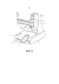
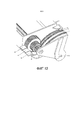
Фиг. 1 - перспективный вид выдачного устройства в соответствии с одним вариантом осуществления настоящего изобретения. Выдачное устройство содержит корпус, образующий внутренний объем для вмещения пачки листовых изделий. Выдачное устройство содержит исполнительный механизм и выдачной элемент, причем исполнительный механизм приводится в действие пользователем для приведения в действие выдачного элемента для выдачи желаемого количества листовых изделий. Исполнительный механизм включает в себя два или более пользовательских интерфейсов, которые имеют форму выступов в изображенном варианте осуществления, которые пользователь может нажимать для сообщения выдачному элементу величины перемещения, соответствующей разному количеству выдаваемых листовых изделий в зависимости от того, который из пользовательских интерфейсов нажат. В данном конкретном варианте осуществления длина хода исполнительного механизма является разной для каждого из разных пользовательских интерфейсов для передачи разных величин движения выдачному элементу для выдачи разных количеств листовых изделий.FIG. 1 is a perspective view of a dispenser in accordance with one embodiment of the present invention. The dispensing device comprises a housing forming an internal volume for accommodating a pack of sheet products. The dispenser comprises an actuator and a dispenser, the actuator being actuated by the user to actuate the dispenser to dispense the desired number of sheet products. The actuator includes two or more user interfaces, which are in the form of protrusions in the depicted embodiment, which the user can click to report to the dispensing element a displacement value corresponding to a different number of sheet products to be dispensed, depending on which of the user interfaces is pressed. In this particular embodiment, the actuator stroke length is different for each of the different user interfaces for transmitting different amounts of movement to the dispensing element for dispensing different quantities of sheet products.
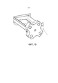
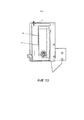
Фиг. 2 изображает более подробно различные части выдачного элемента и исполнительного механизма. Фиг. 2 также изображает опорную конструкцию для передней поверхности пачки, включающей в себя противоположные полки для поддержания противоположных сторон передней поверхности пачки. Между противоположными полками расположен валик выдачного элемента, который зацепляет и зажимает переднюю поверхность пачки. Исполнительный механизм сообщает заданный угол вращения валику, который заставляет валик зацеплять и отделять поочередно один или более листовых изделий. Разный угол вращения сообщается валику в зависимости от того, который из выступов пользовательских интерфейсов нажат, таким образом, обеспечивая селективную выдачу разных количеств листовых изделий.FIG. 2 shows in more detail the various parts of the dispensing element and the actuator. FIG. 2 also depicts a support structure for a front surface of a packet including opposing shelves for supporting opposite sides of a front surface of the packet. Between the opposite shelves is a roller of the dispensing element, which engages and clamps the front surface of the pack. The actuator communicates a predetermined angle of rotation to the roller, which causes the roller to engage and separate one or more sheet products in turn. A different rotation angle is communicated to the roller, depending on which of the protrusions of the user interfaces is pressed, thereby providing selective output of different quantities of sheet products.
Фиг. 3 - вид в разрезе выдачного элемента и исполнительного механизма по осевой линии валика для открытия устройства зубчатой рейки и ведущей шестерни, определяющего взаимосвязь между исполнительным механизмом и выдачным элементом. Эта взаимосвязь является такой, что прямолинейное движение исполнительного механизма вызывает вращательное движение валика. FIG. 3 is a sectional view of a dispensing element and an actuator along an axial line of a roller for opening a gear rack device and a pinion gear defining a relationship between an actuator and a dispensing element. This relationship is such that the rectilinear movement of the actuator causes a rotational movement of the roller.
Фиг. 4 - вид в разрезе, на котором вертикальная взаимосвязь (вертикальное направление, являющееся направлением укладки в пачку) между валиком и проксимальной и дистальной полками опорой конструкции (причем проксимальная полка находится ближе к пользователю). Проксимальная полка расположена таким образом, что пачка должна сгибаться вокруг выдачного валика, в то время как дистальная полка расположена на более высоком уровне вместе с валиком.FIG. 4 is a sectional view in which the vertical relationship (the vertical direction, which is the direction of stacking in the bundle) between the roller and the proximal and distal shelves of the support structure (and the proximal shelf is closer to the user). The proximal flange is positioned so that the bundle should bend around the dispensing roller, while the distal flange is located at a higher level with the roller.
фиг. 5 - более подробный вид устройства зубчатой рейки и ведущей шестерни для преобразования линейного движения подвижной части исполнительного механизма во вращательное движение валика. Один конец хода подвижной части исполнительного механизма определяется за счет упора в участок неподвижной части исполнительного механизма. Другой конец хода подвижной части исполнительного механизма определяется пальцами пользователя, проходящими от одного из выступов пользовательских интерфейсов подвижной части исполнительного механизма, и упором для пальца на неподвижной части исполнительного механизма, в который будет упираться палец пользователя.FIG. 5 is a more detailed view of the gear rack and pinion device for converting the linear motion of the movable part of the actuator into the rotational movement of the roller. One end of the stroke of the movable part of the actuator is determined by focusing on a portion of the stationary part of the actuator. The other end of the stroke of the movable part of the actuator is determined by the fingers of the user extending from one of the protrusions of the user interfaces of the movable part of the actuator, and by the palm rest on the fixed part of the actuator, which will rest the user's finger.
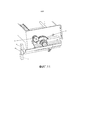
Фиг. 6 изображает множество видов, показывающих, как листовые изделия подаются пользователю во время выдачи. В частности, валик работает относительно близко к проксимальной стороне передней поверхности пачки для отделения проксимальной стороны одного или более листовых изделий от проксимальной полки. Дистальная сторона отделенных листовых изделий надежно удерживается, зажимается между дистальной полкой опорной конструкции и оставшейся частью пачки, чтобы, таким образом, обеспечить местоположение подвешивания, из которого один или более листовых изделий свисают. Выдачное устройство содержит опорный желоб, который входит в контакт и поддерживает одно или более свисающих листовых изделий для уменьшения натяжения, необходимого для подвешивания дистальной стороны свисающих листовых изделий Опорный желоб включает в себя периферийный вырез или выемку для обеспечения захвата пользователем свисающих листовых изделий с противоположных поверхностей.FIG. 6 is a plurality of views showing how sheet products are supplied to a user during delivery. In particular, the roller operates relatively close to the proximal side of the front surface of the stack to separate the proximal side of one or more sheet products from the proximal shelf. The distal side of the separated sheet products is firmly held, clamped between the distal shelf of the support structure and the remaining part of the stack, so as to provide a suspension location from which one or more sheet products hang. The dispenser device includes a support chute that contacts and supports one or more hanging sheet products to reduce the tension required to suspend the distal side of the hanging sheet products. The support chute includes a peripheral cutout or recess to allow the user to grab the hanging sheet products from opposite surfaces.
Фг. 7 изображает пример конструкции валика и ряд альтернативных конструкций. Проиллюстрированный пример конструкции валика образует круглое поперечное сечение, тогда как альтернативные варианты осуществления имеют один или более выступов, лопастей или ребер, или им подобного для зацепления передней поверхности пачки листовых изделий.
Фиг. 8 изображает индексирующее устройство для использования с валиком с выступами, лопастями, ребрами или им подобными выдачного элемента.FIG. 8 shows an indexing device for use with a roller with protrusions, blades, ribs or the like of a dispensing member.
Фиг. 9 изображает вариант осуществления выдачного устройства с модифицированной подставкой, включающей в себя желоб для улавливания любых листовых изделий, которые падают с опорного желоба. Желоб для улавливания включает в себя удерживающие ушки на конце поверхности желоба для улавливания. Желоб для улавливания также включает в себя выемку, так что листовые изделия, поддерживаемые на поверхности желоба для улавливания, захватываются пользователем на противоположных поверхностях. FIG. 9 shows an embodiment of a dispenser with a modified stand including a chute for catching any sheet products that fall from the support chute. The catch chute includes retaining ears at the end of the surface of the catch chute. The capture chute also includes a recess, so that sheet products supported on the surface of the capture chute are gripped by the user on opposing surfaces.
Фиг. 10 раскрывает альтернативный вариант осуществления исполнительного механизма, в котором поворотная ручка используется для сообщения вращательного движения валику, который не показан.FIG. 10 discloses an alternative embodiment of an actuator in which a rotary knob is used to communicate rotational motion to a roller that is not shown.
Фиг. 11 раскрывает альтернативный исполнительный механизм, включающий в себя отдельные нажимные кнопки, связанные с разными устройствами зубчатой рейки и ведущей шестерни, для селективного сообщения углов вращения валику для соответствующей выдачи разных количеств листовых изделий.FIG. 11 discloses an alternate actuator including separate push buttons associated with different gear rack and pinion gears for selectively communicating rotation angles to a roller for correspondingly outputting different quantities of sheet products.
Фиг. 12 изображает первый альтернативный вариант осуществления исполнительного механизма, в котором вместо прямолинейного движения исполнительного механизма, преобразуемого во вращательное движение валика, нажимные кнопки соответствуют траектории вращения, которая передается вращательному движению валика.FIG. 12 depicts a first alternative embodiment of an actuator in which, instead of a rectilinear movement of an actuator that is transformed into a rotational movement of the roller, the push buttons correspond to a rotation path that is transmitted to the rotational movement of the roller.
Фиг. 13 изображает вариант осуществления регулируемого упора, который обеспечивает регулировку местоположения одного конца хода для приведения в действие. Этот элемент обеспечивает регулировку положения упора или остановки подвижной части исполнительного механизма относительно неподвижной части исполнительного механизма для образования разных длин хода. Этот регулировочный элемент позволяет пользователю регулировать длину хода, которая может быть полезной для компенсации разных скользящих свойств, соответствующих разным типам листового изделия, используемого с выдачным устройством.FIG. 13 depicts an embodiment of an adjustable stop that adjusts the location of one end of a stroke for actuation. This element provides adjustment of the position of the stop or stop of the movable part of the actuator relative to the stationary part of the actuator for the formation of different stroke lengths. This adjustment element allows the user to adjust the stroke length, which may be useful to compensate for the different sliding properties corresponding to the different types of sheet products used with the dispenser.
Подробное описание вариантов осуществления настоящего изобретенияDetailed Description of Embodiments of the Present Invention
На фиг. 1 изображен вариант осуществления выдачного устройства 1. Выдачное устройство 1 включает в себя корпус 40, образующий внутренний объем для содержания пачки листовых изделий 10. Листовые изделия могут быть вложены и могут быть салфетками. Более конкретно, листовые изделия имеют функцию протирания. Корпус 40 расположен на подставке 5, имеющей ножки для расположения на горизонтальной поверхности, такой как столешница. Корпус 40 включает в себя дистальную стенку, образующую опорную поверхность для пачки 10, боковые стенки для содержания сбоку пачки 10, и проксимальную стенку 8 для предотвращения вываливания пачки 10 по направлению к пользователю. Передняя стенка 8 в изображенном варианте осуществления включает в себя дверь, которая открывается вокруг шарниров 7 для обеспечения загрузки пачки 10. В альтернативном варианте осуществления вместо двери передняя стенка в качестве альтернативы может включать в себя отверстие, проходящее в направлении укладки в пачку для обеспечения проникновения пользователя во внутренний объем, образованный корпусом 40. Корпус 40 открыт сверху (или сзади в направлении укладки в пачку) для обеспечения загрузки сверху корпуса 40. Когда ножки подставки 5 расположены на горизонтальной поверхности, поверхность дистальной стенки корпуса 40, которая поддерживает края или сгибы в пачке, в этом примере осуществления наклонена назад относительно вертикальной линии.In FIG. 1 shows an embodiment of a dispensing device 1. The dispensing device 1 includes a
Корпус 40 и подставка 5 в данном изображенном варианте осуществления образуют выдачное устройство гравитационной подачи. Аспекты и варианты осуществления, описанные выше, и которые объяснены более подробно ниже, широко используются в разных типах выдачного устройства, таких как, и без ограничения, настольные выдачные устройства салфеток, выдачные устройства свернутой туалетной бумаги, выдачные устройства свернутых или вложенных полотенец для рук, выдачные устройства салфеток на столешнице или выдачные устройства салфеток в рабочем столе. Как указано выше, листовые изделия обычно используются для протирания и могут быть сложены и/или вложены и могут быть бумажными листовыми изделиями.The
На фиг. 1 изображен исполнительный механизм 2, который установлен на боковой стороне корпуса 40, и который функционально соединен с выдачным элементом 3 для принудительной выдачи одного или более листовых изделий. Исполнительный механизм 2 включает в себя разные пользовательские интерфейсы 27, 28, которые определяют разные длины хода исполнительного механизма 2, чтобы, таким образом, дать возможность пользователю выбирать одно из разных количеств листовых изделий, имеющихся в наличии, для выдачи выдачным элементом 3. In FIG. 1, an
На фиг. 2 изображен вариант осуществления выдачного элемента 3 и исполнительного механизма 2 с разделенными различными частями для легкого понимания. Опорная конструкция 12 устанавливается на переднем конце или на нижнем конце корпуса 40. Опорная конструкция 12 образует полки 21, 22 (также см. фиг. 4), которые стыкуются с передней поверхностью пачки 10 листовых изделий. Передняя поверхность пачки листовых изделий 10 образована поверхностью самого переднего листа или листов в пачке 10.In FIG. 2 shows an embodiment of a dispensing
В изображенном варианте осуществления выдачного устройства гравитационной подачи передняя поверхность пачки опирается на полки 21, 22 и поддерживает большую часть веса пачки 10. Задняя поверхность корпуса 40 в данном варианте осуществления воспринимает незначительную часть веса пачки 10. Полки 21, 22 контактируют с противоположными краями передней поверхности пачки листовых изделий и образуют выдачное отверстие 41 в зазоре между полками 21, 22 Опорная конструкция дополнительно включает в себя стенки, окружающие полки 21, 22 для поддержания складчатых или краевых поверхностей переднего участка пачки 10.In the illustrated embodiment of the gravity feed dispenser, the front surface of the stack rests on the
Валик 15 выдачного элемента 3 установлен с возможностью вращения в опорной конструкции 12 в положении рядом с проксимальной полкой 22 (см. фиг. 4), где проксимальная полка 22 является полкой, ближайшей к пользователю во время использовании. Валик 15 состоит из стержня или центрального вала 14, выполненного из относительно жесткого материала, и наружной оболочки 13, которая может быть получена литьем под давлением или получена выдавливанием, и которая может иметь лучшие характеристики зажима относительно материала листовых изделий, по меньшей мере, на наружной поверхности оболочки 13 по сравнению с центральным валом 14. Центральный вал 14 выступает через, по меньшей мере, одну сторону опорной конструкции 12 для соединения с исполнительным механизмом 2 способом, описанным ниже. Эту вступающую часть центрального вала 14 через опору 12 можно видеть на фиг. 3.The
Выдачной элемент 3 дополнительно включает в себя круглую шестерню 23 и муфту 24 одностороннего вращения, установленную на центральном валу 14 валика 15. Круглая шестерня 23 служит в качестве ведущей шестерни, которая взаимодействует с зубчатой рейкой 25 исполнительного механизма 2, описанного более подробно ниже. Муфта 24 одностороннего вращения обеспечивает то, что валик 15 может вращаться только посредством приведения в действие исполнительного механизма 2 в направлении выдачи, поскольку вращение в противоположную сторону может быть вредным для процесса выдачи в изображенном варианте осуществления.The dispensing
Исполнительный механизм 2 может быть дополнительно объяснен со ссылкой на фиг. 2 и 5. Исполнительный механизм 2 включает в себя подвижную часть 19 и неподвижную часть 18. Неподвижная часть 18 исполнительного механизма установлена на боковой стороне корпуса 40 и боковой стороне опорной конструкции 21, в то время как подвижная часть 19 исполнительного механизма установлена на неподвижной части 18 исполнительного механизма для прямолинейного движения относительно нее. Подвижная часть 19 исполнительного механизма включает в себя зубчатую рейку 25 в виде шестерни в изображенном варианте осуществления, которая зацепляется с круглой шестерней 23 выдачного элемента 3 для образования устройства зубчатой рейки и ведущей шестерни. Данное устройство зубчатой рейки и ведущей шестерни преобразует прямолинейное движение подвижной части 19 исполнительного механизма во вращательное движение валика 15.The
Подвижная часть 19 исполнительного механизма включает в себя множество выступов 27, 28 пользовательского интерфейса, которые проксимально расположены на выдачном устройстве 1, и которые имеют размер для контакта с указательным пальцем и средним пальцем пользователя. Пользователь может нажимать на выступы для сообщения прямолинейного движения подвижной части 19 исполнительного механизма и, таким образом, сообщения вращательного движения валику 15. Длина хода подвижной части 19 исполнительного механизма определяет степень, до которой валик 15 перемещается, и, следовательно, количество выдаваемых листовых изделий.The
Неподвижная часть 18 исполнительного механизма 2 включает в себя упор 29 для пальца, в который пальцы пользователя будут упираться при нажатии на один из выступов 27, 28 пользовательского интерфейса. При этом упор 29 для пальца определяет крайнюю точку хода подвижной части 19 исполнительного механизма. Нижний выступ 27 пользовательского интерфейса имеет более короткое расстояние для перемещения перед совмещением с упором 29 для пальца по сравнению с верхним выступом 28 пользовательского интерфейса. Эти два расстояния, таким образом, соответственно определяют более короткое и более длинное перемещения для зубчатой рейки 25, которые, в свою очередь, соответствуют соответственно меньшему и большему углам поворота валика 15. Выступы 27, 28 пользовательского интерфейса соответственно определяют первое количество листовых изделий для выдачи и второе большее количество листовых изделий для выдачи. Например, первый выступ 27 пользовательского интерфейса может соответствовать выдаче одного отдельного листового изделия, или он может соответствовать выдаче одного сгиба из вложенных листовых изделий, что будет, например, таким образом, извлекать/выдавать два отдельных листовых изделия. Второй выступ 28 пользовательского интерфейса может выдавать дважды это количество, таким образом, он может выдавать два отдельных листовых изделий или два сгиба вложенных листовых изделий, конкретно, четыре отдельных листовых изделий.The
Подвижная часть 19 исполнительного механизма упирается в опорный участок 42, который образует исходное положение подвижной части 19 исполнительного механизма относительно неподвижной части 18 исполнительного механизма. Хотя не показано, подвижная часть 19 исполнительного механизма смещается для возврата в исходное положение, образованное подвижной частью 19 исполнительного механизма, упирающейся в опорный участок 42 неподвижной части 18 исполнительного механизма, например, при помощи пружины. Муфта 24 одностороннего вращения обеспечивает передачу вращения круглой шестерни 23 центральному валу 14 валика 15, когда пользователь сообщает прямолинейное движение зубчатой рейке 25 посредством перемещения подвижной части 19 исполнительного механизма. Однако, когда пружина возвращает подвижную часть 19 исполнительного механизма обратно в ее исходное положение при использовании опорного участка 42, муфта 24 одностороннего вращения заставляет круглую шестерню 23 зацепляться, чтобы не сообщать дополнительно вращательное движение центральному валу 14 или любому другому участку валика 15.The
Ссылаясь на фиг. 4, на этом чертеже изображены взаимные расположения проксимальной полки 22, дистальной полки 21 и валика 15. В частности, на этом чертеже изображены полки 21, 22 и наружная поверхность валика 15, расположенного обычно на одной прямой относительно направления укладки в пачку, так что передняя поверхность пачки 10 контактирует и поддерживается на дистальной опорной полке 21, валике 15 и проксимальной опорной полке 22. Валик 15 расположен рядом с проксимальной опорной полкой 22, и выдачное отверстие 41 образовано в зазоре между дистальной опорной полкой 21 и валиком 15. По меньшей мере, участок наружной поверхности валика 15 расположен над проксимальной опорной полкой 22 для принудительного сгиба передней поверхности пачки 10 вокруг валика 15 до некоторой степени для обеспечения большой площади контакта и также достаточного давления межу самым передним листовым изделием и валиком 15 для предотвращения или, по меньшей мере, минимизации проскальзывания. Валик 15 выполняет функцию зажима основной поверхности части листового изделия спереди пачки и удаления ее с проксимальной полки 22 посредством ее скольжения относительно нижележащего листа в пачке. Валик 15 затем передает листовое изделие в выдачное отверстие 41, когда сгиб или край зажатого листового изделия перемещен за валик 15. Когда конкретное листовое изделие было перемещено в выдачное отверстие 41/через выдачное отверстие 41, следующий лист в пачке будет находиться на валике 15.Referring to FIG. 4, this drawing shows the relative positions of the proximal flange 22, the
Валик 15 в данном варианте осуществления имеет круглое поперечное сечение. Наружная поверхность валика 15 необходима для зажима материала листового изделия. Соответственно, наружная поверхность валика 15 может включать в себя абразивную бумагу, может быть тисненной или может включать в себя выемки или ребра, или может быть выполнена из материала, который имеет большую фрикционную связь с материалом, образующим листовое изделие, таким как эластомерный материал. Наружная поверхность может дополнительно или в качестве альтернативы включать в себя рисунок с канавками или выступами, такой как рисунок с насечками, для улучшения зажима. В других вариантах с улучшенным зажимом наружная поверхность валика 15 может быть образована за счет проходящих в осевом направлении или радиальном направлении зубцов, причем зубцы наклонены под углом к направлению вращения или против направления вращения при выдаче листового изделия, или они могут иметь прямоугольный или заостренный профиль.The
Валик 15 вращается так, что его наружная поверхность перемещается в направлении от проксимальной полки 22 к дистальной полке 21 в местоположении зацепления с передней поверхность пачки 10. Это заставляет листовое изделие удаляться от проксимальной полки 22 к дистальной полке 21. Таким образом, валик 15 не заставляет листовое изделие удаляться с дистальной полки 21, так что проксимальная часть листового изделия перемещается в/через выдачное отверстие 41, в то время как дистальный край листового изделия остается поддерживаемым на дистальной полке 21, зажатым между оставшейся частью пачки и дистальной полкой 21. По существу, листовое изделие, зажатое валиком 15, будет отделяться в/через выдачное отверстие 41 и свешиваться подвешенным за дистальный край на дистальной полке 21.The
Ссылаясь на фиг. 4, опорная конструкция 12 может включать в себя проксимальные ребра, проходящие в направлении укладки в пачку на проксимальной полке 22, для зацепления проксимальной стороны переднего участка пачки 10 для обеспечения того, чтобы пачка соответственно была прижата к валику 15.Referring to FIG. 4, the
Это не просто степень зажима между валиком 15 и листовым изделием, но также высота проксимальной полки 22 и угол наклона корпуса 40 относительно вертикальной линии, что служит для регулировки давления между самым передним листом в пачке 10 и валиком 15 в данном варианте осуществления. Высота проксимальной полки 22 в направлении укладки в пачку может регулироваться, например, регулятором, управляемым пользователем, для снятия или увеличения этого давления, так что конфигурация опорной конструкции 12 оптимизирована для обеспечения того, чтобы нужное количество листовых изделий выдавалось в соответствии с выбором пользователя через исполнительный механизм 2. This is not just the degree of clamping between the
Степень, до которой корпус 40 заполняется пачкой листовых изделий, может влиять на результирующее давление на валик 15. В одном варианте осуществления линия 6 заполнения (фиг. 1) показывает пользователю уровень пачки, который должен поддерживаться для заданной функции выдачного устройства. В качестве альтернативы, вес может быть приложен дополнительно к весу пачки для обеспечения соответствующего давления на валик 15. В еще одном альтернативном варианте осуществления смещающий элемент, такой как пружина, будет толкать пачку на валик 15.The degree to which the
Ссылаясь на фиг. 1 и 6c, обеспечен опорный желоб 4, который расположен под выдачным отверстием 41. Опорный желоб 4 расположен под дистальной полкой 21, так что листовые изделия, свисающие в выдачное отверстие 41, подвешенные за дистальный край, расположены на опорном желобе 4. Опорный желоб 4 выполняет функцию уменьшения отчасти веса листового изделия, под действием которого это листовое изделие стремится удалиться от дистальной полки 21, что будет приводить к нежелательному полному или неуправляемому отделению листовых изделий от опорной конструкции 12. Опорный желоб 4 включает в себя периферийный вырез 30, расположенный так, что свисающее листовое изделие или изделия находятся над вырезом 30, таким образом, обеспечивая захват пользователем свисающего листового изделия (листовых изделий с обеих сторон, одной стороны через вырез 30. Выемка вместо выреза может обеспечивать подобную функцию. Опорный желоб 4 наклонен под углом для сгиба сгибов или краев свисающих листовых изделий по направлению к пользователю для удобства захвата и качества подачи. Опорный желоб 4, таким образом, обеспечивает скольжение под углом, препятствуя непосредственному вертикальному свисанию листовых изделий.Referring to FIG. 1 and 6c, a
Со ссылкой на фиг. 1-5 вместе с фиг. 6 ниже будет описан пример работы выдачного устройства. Для выдачи желаемого количества листовых изделий, таких как салфетки, пользователь нажимает пальцами на выступ 27 пользовательского интерфейса или на выступ 28 пользовательского интерфейса в зависимости от того, требуется ли меньшее или большее количество листовых изделий. Например, если выдачное устройство 1 расположен в окне для обслуживания не выходя из машины, выступ 27 пользовательского интерфейса может быть связан с небольшим заказом продуктов питания, и выступ 28 пользовательского интерфейса может быть связан с большим заказом продуктов питания. Дополнительные пользовательские интерфейсы могут быть предусмотрены для обеспечения большего диапазона количеств листовых изделий, которые могут выдаваться. Подвижная часть 19 исполнительного механизма перемещается прямолинейно под направлением пользователя, нажимающего на один из выступов 27, 28 пользовательских интерфейсов. Прямолинейное движение подвижной части 19 исполнительного механизма преобразуется во вращательное движение валика 15 с помощью устройства зубчатой рейки и ведущей шестерни.With reference to FIG. 1-5 together with FIG. 6 below will be described an example of the dispensing device. To deliver the desired number of sheet products, such as napkins, the user presses fingers on the
Пачка 10 расположена в корпусе 40 и опирается на дистальную и проксимальную полки 21, 22. Передняя поверхность пачки 10 частично сгибается вокруг валика 15 в результате относительного расположения дистальной и проксимальной полок 21, 22. Валик 15 прижат к передней поверхности пачки листовых изделий для зацепления самого переднего листового изделия, а не к краям или сгибам, что будет иметь место в случае зацепления боковых поверхностей пачки. Вращение валика 15 заставляет самое переднее листовое изделие пачки 10 в зацеплении с ним перемещаться назад относительно проксимальной полки 22 способом, который включает в себя скольжение от нижележащего листа в пачке. Зажим между наружной поверхностью валика 15 и самым передним листовым изделием сильнее, чем соответствующая сила трения между передним листовым изделием и нижележащим листовым изделием в пачке 10, так что листовое изделие может скользить или перемещаться относительно нее. Когда самое переднее листовое изделие удалено от проксимальной полки 22, непрерывное вращение валика приводит к тому, что край зажатого листового изделия перемещается за валик 15 и в выдачное отверстие 41.The
Когда листовое изделие отделено валиком 15, листовое изделие в изображенном варианте осуществления выдачного устройства гравитационной подачи будет отделяться от проксимального края или сгиба в свешивающееся положение, проходя через выдачное отверстие 41. На дистальный край листового изделия валик 15 не действует и, таким образом, он остается зажатым между проксимальной полкой 21 и оставшейся частью пачки 10 для обеспечения точки подвески, обеспечивающей свисание листового изделия.When the sheet product is separated by a
В зависимости от того, который из выступов 27, 28 пользовательских интерфейсов нажат, вышеописанный процесс выдачи будет повторяться посредством поворота выдачного валика 15 на разный угол, так что одно или множество листовых изделий свисают через выдачное отверстие 41, подвешенные на дистальной полке 21. Свисающие листовые изделия будут расположены отчасти на нижележащем опорном желобе 4, готовые для захвата пользователем. Затем, пользователь может подойти и захватить с обеих сторон свисающие листовые изделия, используя вырез 30 в опорном желобе 4, и тянуть их для освобождения свисающих листовых изделий от зажатия на дистальной полке 21. Затем, листовые изделия могут быть уложены в мешки или сразу использоваться для протирания.Depending on which of the
Ссылаясь на фиг. 6b, можно видеть, что свисающие листовые изделия образуют конец 44, который проходит за опорный желоб 4. Это может являться результатом использования валика 15 в устройстве для вложенных листовых изделий. Ссылаясь на фиг. 6a, начальное положение конца 44 можно видеть до того, как валик 16 будет приведен в действие для освобождения листового изделия, связанного с концом 44. Этот конец 44 не зажат на дистальном краю между оставшейся частью пачки и дистальной полкой 21, так что когда валик 15 поворачивается, конец 44 свисает за свернутые листовые изделия, которые все еще подвешены на дистальной полке 21. Предположив, что пользователь захватывает свисающие листовые изделия, изображенные на фиг. 6b, это будет вытягивать новый конец самого переднего листового изделия в пачке, таким образом, получая расположение следующего листового изделия, как показано на фиг. 6a. Этот конец 44 загибается за свисающими листовыми изделиями пользователем при захвате их, таким образом, дополнительно используя периферийный вырез 30 опорного желоба 44. Referring to FIG. 6b, it can be seen that the overhanging sheet products form an end 44 that extends beyond the
Ряд модификаций или дополнений может быть выполнен специалистом в данной области техники в вышеупомянутом варианте осуществления.A number of modifications or additions may be made by a person skilled in the art in the aforementioned embodiment.
В вышеупомянутых вариантах осуществления поперечное сечение валика 15 обычно является круглым, как показано, например, на фиг. 4 и 7i. На фиг. 7a-7h изображены другие варианты, в которых поперечное сечение отличается от поперечного сечения примера валика 15. В этих альтернативных вариантах осуществления профиль валика включает в себя ребра, лопасти или выступы. Между ребрами, лопастями или выступами образованы относительно утопленные части профиля, которые будут скользить, например, скользить или не контактировать, относительно передней поверхности пачки 10. Скользящие части альтернативных конструкций валика обеспечивают выдачу самого переднего листового изделия без смещения следующего листа, в результате чего скользящая часть валика располагается в соответствии со следующим листом. Это только, когда валик дополнительно вращается, так что следующее ребро, лопасть или выступ зацепляет и зажимает следующий лист, когда следующий лист начинает выдаваться. In the above embodiments, the cross section of the
Индексирующая система может использоваться совместно с некруглыми конфигурациями валика для обеспечения заданного начального положения для конкретного ребра, лопасти или выступа, таким образом, обеспечивая то, что процесс выдачи, выбранный пользователем через исполнительный механизм 2, осуществляется соответствующим образом. Несимметричные конфигурации валика на фиг. 7a-7h включают в себя конкретное начальное положение для валика в процессе выдачи в результате зацепления, зажима и перемещения самого переднего листа из пачки 10 в выдачное отверстие 41, исходя из установленной величины перемещения в исполнительном механизме 2. Пример индексирующей системы 45 изображен на фиг. 8.The indexing system can be used in conjunction with non-circular configurations of the roller to provide a predetermined starting position for a particular rib, blade or protrusion, thereby ensuring that the issuing process selected by the user through the
На фиг. 8 барабанный кулачок 46 установлен на центральном валу 14 валика и вращается вместе с центральным валом 14 валика. Барабанный кулачок 46 может быть установлен на другой стороне опорной конструкции 12 относительно исполнительного механизма 2. Кулачковый следящий элемент 47 смещается пружиной 49 кручения к наружному профилю барабанного кулачка 46. Наружный профиль барабанного кулачка 46 включает в себя утопленные участки 48, которые соответствуют начальной или конечной точкам, как определено, по меньшей мере, одним ребром, лопастью или выступом валика. Таким образом, если цикл выдачи не заканчивается для подачи листового изделия в выдачное отверстие 41, смещающее усилие, которому подвергается кулачковый следящий элемент 47, будет стремиться проталкивать или, по меньшей мере, смещать установку кулачкового следящего элемента 47 и утопленных участков 48 барабанного кулачка 46. Например, если пользователь не завершает ход приведения в действие, индексирующая система 45 может завершать этот ход приведения в действие для обеспечения того, что выдалось требуемое количество листовых изделий, и также для обеспечения того, чтобы заданная начальная точка для валика в цикле выдачи была обеспечена для следующего использования.In FIG. 8, the
Ссылаясь на фиг. 9, изображен альтернативный вариант осуществления. В одной модификации обеспечен желоб 50 для улавливания, который расположен между ножками подставки 5 и установлен для улавливания любых листовых изделий, которые падают из выдачного отверстия 41 и опорного желоба 4. Желоб 50 для улавливания содержит наклонную поверхность для скольжения вниз для любых листовых изделий, которые упали, и также включает в себя ушки 53 для прекращения перемещения упавших листовых изделий, чтобы удерживать их подвешенными на поверхности скольжения. Желоб 50 для улавливания дополнительно содержит утопленный участок 51, который обычно расположен в центре и утоплен относительно поверхности скольжения желоба 50 для улавливания, и который содержит отверстие рядом с ушками 53 для обеспечения захвата пользователем листовых изделий с обеих поверхностей.Referring to FIG. 9, an alternative embodiment is shown. In one embodiment, a
На фиг. 9 изображена дополнительная модификация, которая была упомянута как возможность в вышеприведенном описании дополнительного выступа 52 пользовательского интерфейса, так что может выдаваться третье еще большее количество листовых изделий. Данный вариант осуществления имеет первый, второй и третий выступы 27, 28 и 52 пользовательских интерфейсов для обеспечения выбора пользователем между небольшим, средним и большим количествами листовых изделий, которые могут соответствовать небольшому, среднему и большому заказам пищевых продуктов, например, в окне обслуживания не выходя из машины блюдами быстрого приготовления. Каждый из выступов 27, 28 и 52 пользовательских интерфейсов определяет разные длины хода для подвижной части 19 исполнительного механизма, которые соответствуют разным соответствующим углам поворота валика 15. В качестве примера первый выступ 27 пользовательского интерфейса может заставлять валик 15 поворачиваться на угол, достаточный для выдачи одного сгиба вложенных листовых изделий, таким образом, обеспечивая два отдельных листовых изделия. Подобным образом, второй выступ 28 пользовательского интерфейса может соответствовать выдаче четырех отдельных листовых изделий, и третий выступ 52 пользовательского интерфейса может соответствовать выдаче шести отдельных листовых изделий.In FIG. 9 shows an additional modification that has been mentioned as a possibility in the above description of an
Ссылаясь на фиг. 10, изображен вариант осуществления первого и третьего аспектов, в котором исполнительный механизм имеет форму зубчатой поворотной ручки, которая зацепляется с шестерней, установленной на центральном валу 14 валика 15. В этом альтернативном варианте осуществления исполнительный механизм передает вращательное движение, сообщаемое пользователем, чтобы вызвать вращательное движение валика 15.Referring to FIG. 10, an embodiment of the first and third aspects is shown in which the actuator is in the form of a gear rotary knob that engages with a gear mounted on the
На фиг. 11 изображен другой альтернативный вариант осуществления, в котором обеспечено три отдельных нажимных кнопки 61, 62, 63, которые перемещаются на одинаковый ход при приведении в действие, но соответственно передают разные углы вращения валику 15 для принудительной выдачи разных количеств листовых изделий. В этом конкретном варианте осуществления каждая из нажимных кнопок 61, 62, 63 соответственно соединена с шестерней зубчатой рейки, которая зацепляется с блоком 65 шестерен. Блок 65 шестерен зацепляется с шестерней 64, соединенной с валиком 15. Блок 65 шестерен имеет шестерни разных размеров, соответственно зацепляющиеся с одной из шестерен зубчатой рейки, соединенных с нажимными кнопками 61, 62, 63. Блок 65 шестерен, таким образом, передает разные углы вращения шестерне 64 для передачи разных углов вращения валику 15 в зависимости от того, которая из нажимных кнопок 61, 62, 63 нажата. Кроме того, в варианте осуществления на фиг. 11, нажимные кнопки 61, 62, 63 перемещаются перпендикулярно к направлению укладки в пачку, а не параллельно направлению укладки в пачку, что и в случае с вариантами осуществления на фиг. 1-9 для принудительного вращения валика 15. In FIG. 11 depicts another alternative embodiment in which three
На фиг. 12 изображен еще один альтернативный вариант осуществления. На фиг. 12 исполнительный механизм включает в себя три разные нажимные кнопки 66, 67, 68, которые передают разные углы вращения валику 15, используя одну и ту же длину хода. В частности, обеспечен блок 69 шестерен, который имеет шестерни разного размера, которые зацепляются с секторными шестернями 70, 71, 72, соответственно соединенными с первой-третьей нажимными кнопками 66, 67, 68. Подобно предыдущему альтернативному варианту осуществления на фиг. 11, длина хода, связанная с каждой из нажимных кнопок 66, 67, 68, является одинаковой при соответственной выдаче разных количеств листовых изделий, которое обеспечивается с помощью блока 69 шестерен, имеющего шестерни разного размера. В альтернативном варианте осуществления на фиг. 12 каждая из нажимных кнопок 66, 67, 68 перемещается по дуге, поворачиваясь вокруг оси 73 поворота для осуществления процесса выдачи. Таким образом, различные варианты осуществления обеспечивают прямолинейное движение вдоль разных осей, дугообразное движение и вращательное движение для пользовательского интерфейса для приведения в действие.In FIG. 12 shows yet another alternative embodiment. In FIG. 12, the actuator includes three
На фиг. 13 изображен один пример модификации, в котором исполнительный механизм включает в себя регулируемый ограничитель 75, обеспечивающий регулировку начальной и конечной точки хода для приведения в действие для точного определения длины хода для приведения в действие для обеспечения того, чтобы выдалось заданное количество листовых изделий. В частности, разные свойства листа (такие как толщина листа, глубина тиснения и/или материал) листовых изделий могут вызывать незначительное изменение в отношении между углом вращения валика и количеством выдаваемых листовых изделий. Соответственно, исполнительный механизм или устройство для выдачи может включать в себя регулятор для компенсации изменений в этом отношении для разных типов листового изделия. В варианте осуществления на фиг. 13 ограничитель 75 может регулироваться для уменьшения или увеличения длины хода, таким образом, изменяя угол вращения выдачного валика для каждого из выступов 27, 28 пользовательских интерфейсов.In FIG. 13 depicts one example of a modification in which the actuator includes an
В другом альтернативном варианте осуществления исполнительный механизм может быть электронным. В частности, электродвигатель может быть установлен для вращения выдачного валика. Кроме того, одна или более кнопок для приведения в действие могут использоваться для выдачи заданного количества листовых изделий. В одном варианте осуществления электронного исполнительного механизма могут быть обеспечены соответствующие кнопки управления, которые заставляют электродвигатель вращать выдачной валик на разный угол для соответствующей выдачи разных количеств листовых изделий.In another alternative embodiment, the actuator may be electronic. In particular, an electric motor may be mounted to rotate the dispensing roller. In addition, one or more buttons for actuation can be used to dispense a predetermined number of sheet products. In one embodiment of the electronic actuator, appropriate control buttons may be provided that cause the electric motor to rotate the dispensing roller at a different angle to accordingly dispense different quantities of sheet products.
Ссылаясь на фиг. 4, полки 21, 22 выполнены в виде плоских выступов, хотя также предусмотрены альтернативные формы полок. Например, стержень или стержни могут использоваться вместо проксимальной полки 22 и/или дистальной полки 21. Такие стержень или стержни будут все еще выполнены в форме полки и поддерживать край передней поверхности пачки, позволяя их описывать в виде полок. Referring to FIG. 4, the
В другом альтернативном варианте осуществления и со ссылкой на фиг. 2, валик 15 может быть ориентирован в совмещении с короткой стороной пачки, а не с длинной стороной пачки. В таком варианте осуществления полки 21, 22 могут быть также расположены на противоположных коротких сторонах пачки для контакта с краями коротких сторон передней стороны пачки, а не с длинными сторонами, как показано.In another alternative embodiment and with reference to FIG. 2, the
Варианты осуществления, описанные в данном документе, также предусматривают альтернативный процесс выдачи, который избавляет пользователя от приведения в действие исполнительного механизма. Возвращаясь к фиг. 6(a), пользователь может просто захватывать конец 44 для выдачи самого переднего листового изделия. В одном альтернативном варианте пользователь, захватывающий конец 44, может выдавать первое количество листовых изделий (например, два), и исполнительный механизм может быть выполнен с возможностью принудительной выдачи выдачным элементом второго и третьего больших количеств листовых изделий (например, четыре и шесть, соответственно).The embodiments described herein also provide an alternative issuing process that eliminates the need for the user to actuate the actuator. Returning to FIG. 6 (a), the user can simply grab the end 44 to dispense the frontmost sheet product. In one alternative embodiment, the user, the gripping end 44, can issue the first number of sheet products (for example, two), and the actuator can be configured to force the dispensing element of the second and third large quantities of sheet products (for example, four and six, respectively) .
В другом альтернативном варианте осуществления выдачное устройство включает в себя более одного выдачных валиков. Ссылаясь на фиг. 4, выдачное устройство может включать в себя множество выдачных валиков, которые зацепляют переднюю поверхность пачки, и которые перемещаются для выдачи одного или более листовых изделий. Например, выдачные валики могут перемещаться вместе или отдельно. В одном варианте работа исполнительного механизма может заставлять выдачные валики перемещаться вместе для выдачи одного или более листовых изделий. В альтернативном варианте исполнительный механизм может приводить в действие разные выдачные валики в зависимости от того, какой пользовательский интерфейс приведен в действие. Разные выдачные валики могут быть выполнены, например, разделены по размерам, с возможностью выдачи разных соответствующих количеств листовых изделий.In another alternative embodiment, the dispensing device includes more than one dispensing rollers. Referring to FIG. 4, the dispensing device may include a plurality of dispensing rollers that engage the front surface of the stack and that are moved to dispense one or more sheet products. For example, dispensing rollers can be moved together or separately. In one embodiment, the operation of the actuator may cause the dispensing rollers to move together to dispense one or more sheet products. Alternatively, the actuator may actuate different dispensing rollers depending on which user interface is actuated. Different dispensing rollers can be made, for example, divided by size, with the possibility of issuing different corresponding quantities of sheet products.
Claims (25)
Applications Claiming Priority (1)
| Application Number | Priority Date | Filing Date | Title |
|---|---|---|---|
| PCT/EP2013/056726 WO2014154285A1 (en) | 2013-03-28 | 2013-03-28 | Sheet product dispenser |
Publications (1)
| Publication Number | Publication Date |
|---|---|
| RU2615110C1 true RU2615110C1 (en) | 2017-04-03 |
Family
ID=48049994
Family Applications (1)
| Application Number | Title | Priority Date | Filing Date |
|---|---|---|---|
| RU2015134551A RU2615110C1 (en) | 2013-03-28 | 2013-03-28 | Dispensing device for sheet products |
Country Status (11)
| Country | Link |
|---|---|
| US (1) | US10729289B2 (en) |
| EP (1) | EP2978352B1 (en) |
| CN (1) | CN105377098B (en) |
| AU (1) | AU2013384388B2 (en) |
| CA (1) | CA2900588C (en) |
| DK (1) | DK2978352T3 (en) |
| ES (1) | ES2637838T3 (en) |
| MX (1) | MX362011B (en) |
| PL (1) | PL2978352T3 (en) |
| RU (1) | RU2615110C1 (en) |
| WO (1) | WO2014154285A1 (en) |
Cited By (1)
| Publication number | Priority date | Publication date | Assignee | Title |
|---|---|---|---|---|
| RU2771123C1 (en) * | 2019-03-11 | 2022-04-26 | Эссити Хайджин Энд Хелт Актиеболаг | Insert dispenser for dispensing sheet products |
Families Citing this family (9)
| Publication number | Priority date | Publication date | Assignee | Title |
|---|---|---|---|---|
| CN105050469B (en) | 2013-03-28 | 2019-11-05 | 易希提卫生与保健公司 | Sheet product dispenser |
| USD782329S1 (en) * | 2015-08-05 | 2017-03-28 | Ken Sobel | Dispenser for tissues and hand-pulled paper products |
| USD806573S1 (en) * | 2015-08-05 | 2018-01-02 | Ken Sobel | Dispenser for tissues and hand-pulled paper products |
| WO2018127301A1 (en) | 2017-01-09 | 2018-07-12 | Sca Hygiene Products Ab | Dispenser for sheet products and operating method |
| PL3565447T3 (en) | 2017-01-09 | 2024-01-03 | Essity Hygiene And Health Aktiebolag | Dispenser for sheet products and operating method |
| CN108327968B (en) * | 2018-03-21 | 2024-01-12 | 佛山市邦贝机械制造有限公司 | Full-servo automatic slicing machine |
| US11116365B2 (en) | 2019-12-18 | 2021-09-14 | Essity Hygiene And Health Aktiebolag | Horizontally oriented paper product dispenser and related methods |
| US10980377B1 (en) | 2019-12-18 | 2021-04-20 | Essity Hygiene And Health Aktiebolag | Apparatus and methods for paper dispensing |
| US20220227568A1 (en) * | 2021-01-19 | 2022-07-21 | Fania Brunache | Glove Dispenser Assembly |
Citations (5)
| Publication number | Priority date | Publication date | Assignee | Title |
|---|---|---|---|---|
| US1703594A (en) * | 1926-01-04 | 1929-02-26 | Raymond C Pratt | Dispensing machine |
| FR1285715A (en) * | 1961-04-05 | 1962-02-23 | Callaway Mills Co | Tea towel dispensing machine |
| US20080135570A1 (en) * | 2004-09-17 | 2008-06-12 | Elix Co., Ltd. | Apparatus for Discharging Tissue |
| US20100114366A1 (en) * | 2008-10-10 | 2010-05-06 | Georgia Pacific Consumer Products, Lp | Dispensers providing controlled dispensing and controlled dispensing methods |
| EP2335541A2 (en) * | 2009-12-09 | 2011-06-22 | Wausau Paper Towel & Tissue, LLC | Interleaved towel dispenser |
Family Cites Families (23)
| Publication number | Priority date | Publication date | Assignee | Title |
|---|---|---|---|---|
| US2092166A (en) | 1934-06-22 | 1937-09-07 | Jr Richard C Kettles | Dispensing device |
| US2772021A (en) | 1952-01-16 | 1956-11-27 | Richard C Kettles | Towel dispensing device |
| US2932426A (en) | 1955-03-18 | 1960-04-12 | Fort Howard Paper Co | Dispensing devices for paper towels |
| US3117694A (en) * | 1960-05-16 | 1964-01-14 | John R Gothreau | Automatic dispenser of individual flat sheets from a stack |
| US3208634A (en) | 1963-04-11 | 1965-09-28 | Saxe Brothers Inc | Reciprocating member napkin dispenser |
| US3606125A (en) | 1969-08-26 | 1971-09-20 | Towlsaver Inc | Lever actuated roll towel dispenser |
| SE425378B (en) * | 1980-04-25 | 1982-09-27 | Datasaab Ab | SET AND DEVICE FOR CREATING A STACK OF SHEET FORMS, EXAMPLE PAYMENTS, AND ANY SELECTED THESE FORMS |
| US5630581A (en) * | 1996-01-05 | 1997-05-20 | Rodesch Associates, Inc. | Apparatus for dispensing lightweight sheet-style articles from a stacked supply of articles |
| US6622888B2 (en) | 2001-03-09 | 2003-09-23 | Georgia-Pacific Corporation | Metering napkin dispenser |
| US7219852B2 (en) | 2004-08-18 | 2007-05-22 | Kimberly-Clark Worldwide, Inc. | Dispenser for multiple rolls of sheet material |
| US7234610B2 (en) | 2005-02-10 | 2007-06-26 | Northern Products Development Group Llc | Automatic napkin dispenser |
| US20060273101A1 (en) | 2005-06-07 | 2006-12-07 | Kimberly-Clark Worldwide, Inc. | Container and cartridge for dispensing paper products |
| US7543423B2 (en) | 2005-12-13 | 2009-06-09 | Kimberly-Clark Worldwide, Inc. | Vertical carton loading process and system for clips of a stacked sheet material |
| US20070215634A1 (en) * | 2006-03-15 | 2007-09-20 | Marda Medical | Individual containers for use in medical pad warming units |
| US7896285B2 (en) | 2008-02-27 | 2011-03-01 | Georgia-Pacific Consumer Products Lp | Sheet product dispenser |
| US8590738B2 (en) | 2009-03-06 | 2013-11-26 | Sca Tissue North America Llc | Paper product dispensing system |
| JP5382517B2 (en) * | 2009-07-15 | 2014-01-08 | 株式会社リコー | Image forming apparatus |
| RU2013105270A (en) | 2010-07-08 | 2014-08-20 | Ска Хайджин Продактс Аб | DISPLAY DEVICE |
| WO2012134362A1 (en) * | 2011-03-29 | 2012-10-04 | Sca Hygiene Products Ab | Hygienic container |
| CN202376008U (en) | 2011-12-15 | 2012-08-15 | 东风汽车有限公司 | Vehicle-mounted semi-automatic tissue box |
| CN105050469B (en) | 2013-03-28 | 2019-11-05 | 易希提卫生与保健公司 | Sheet product dispenser |
| CN105431069A (en) | 2013-03-28 | 2016-03-23 | Sca卫生用品公司 | Sheet product dispenser |
| US9345368B2 (en) | 2014-05-19 | 2016-05-24 | Sca Hygiene Products Ab | Paper product dispenser and related methods |
-
2013
- 2013-03-28 ES ES13714613.0T patent/ES2637838T3/en active Active
- 2013-03-28 CN CN201380073217.9A patent/CN105377098B/en active Active
- 2013-03-28 AU AU2013384388A patent/AU2013384388B2/en active Active
- 2013-03-28 PL PL13714613T patent/PL2978352T3/en unknown
- 2013-03-28 WO PCT/EP2013/056726 patent/WO2014154285A1/en active Application Filing
- 2013-03-28 MX MX2015013641A patent/MX362011B/en active IP Right Grant
- 2013-03-28 US US14/780,051 patent/US10729289B2/en active Active
- 2013-03-28 EP EP13714613.0A patent/EP2978352B1/en active Active
- 2013-03-28 CA CA2900588A patent/CA2900588C/en active Active
- 2013-03-28 RU RU2015134551A patent/RU2615110C1/en active
- 2013-03-28 DK DK13714613.0T patent/DK2978352T3/en active
Patent Citations (5)
| Publication number | Priority date | Publication date | Assignee | Title |
|---|---|---|---|---|
| US1703594A (en) * | 1926-01-04 | 1929-02-26 | Raymond C Pratt | Dispensing machine |
| FR1285715A (en) * | 1961-04-05 | 1962-02-23 | Callaway Mills Co | Tea towel dispensing machine |
| US20080135570A1 (en) * | 2004-09-17 | 2008-06-12 | Elix Co., Ltd. | Apparatus for Discharging Tissue |
| US20100114366A1 (en) * | 2008-10-10 | 2010-05-06 | Georgia Pacific Consumer Products, Lp | Dispensers providing controlled dispensing and controlled dispensing methods |
| EP2335541A2 (en) * | 2009-12-09 | 2011-06-22 | Wausau Paper Towel & Tissue, LLC | Interleaved towel dispenser |
Cited By (1)
| Publication number | Priority date | Publication date | Assignee | Title |
|---|---|---|---|---|
| RU2771123C1 (en) * | 2019-03-11 | 2022-04-26 | Эссити Хайджин Энд Хелт Актиеболаг | Insert dispenser for dispensing sheet products |
Also Published As
| Publication number | Publication date |
|---|---|
| CA2900588C (en) | 2018-05-22 |
| MX362011B (en) | 2019-01-03 |
| US20160051100A1 (en) | 2016-02-25 |
| US10729289B2 (en) | 2020-08-04 |
| DK2978352T3 (en) | 2017-10-30 |
| ES2637838T3 (en) | 2017-10-17 |
| PL2978352T3 (en) | 2018-01-31 |
| EP2978352B1 (en) | 2017-08-09 |
| CN105377098A (en) | 2016-03-02 |
| CA2900588A1 (en) | 2014-10-02 |
| EP2978352A1 (en) | 2016-02-03 |
| MX2015013641A (en) | 2016-02-18 |
| AU2013384388B2 (en) | 2017-02-02 |
| WO2014154285A1 (en) | 2014-10-02 |
| AU2013384388A1 (en) | 2015-09-03 |
| CN105377098B (en) | 2018-02-16 |
Similar Documents
| Publication | Publication Date | Title |
|---|---|---|
| RU2615110C1 (en) | Dispensing device for sheet products | |
| RU2628746C2 (en) | Sheet product dispenser | |
| AU2013384387B2 (en) | Sheet product dispenser | |
| US10420444B2 (en) | Hands-free flowable material dispensers and related methods | |
| CA2864324C (en) | Automatic napkin dispenser | |
| US6789694B1 (en) | Napkin dispenser | |
| AU2013384385B9 (en) | Sheet product dispenser | |
| CA3066380A1 (en) | Hands-free flowable material dispensers and related methods |
Legal Events
| Date | Code | Title | Description |
|---|---|---|---|
| PD4A | Correction of name of patent owner |