RU2612562C2 - Optical device for generating light beam - Google Patents
Optical device for generating light beam Download PDFInfo
- Publication number
- RU2612562C2 RU2612562C2 RU2013153890A RU2013153890A RU2612562C2 RU 2612562 C2 RU2612562 C2 RU 2612562C2 RU 2013153890 A RU2013153890 A RU 2013153890A RU 2013153890 A RU2013153890 A RU 2013153890A RU 2612562 C2 RU2612562 C2 RU 2612562C2
- Authority
- RU
- Russia
- Prior art keywords
- lens
- optical device
- light
- section
- lighting
- Prior art date
Links
Images
Classifications
-
- F—MECHANICAL ENGINEERING; LIGHTING; HEATING; WEAPONS; BLASTING
- F21—LIGHTING
- F21V—FUNCTIONAL FEATURES OR DETAILS OF LIGHTING DEVICES OR SYSTEMS THEREOF; STRUCTURAL COMBINATIONS OF LIGHTING DEVICES WITH OTHER ARTICLES, NOT OTHERWISE PROVIDED FOR
- F21V5/00—Refractors for light sources
- F21V5/04—Refractors for light sources of lens shape
-
- F—MECHANICAL ENGINEERING; LIGHTING; HEATING; WEAPONS; BLASTING
- F21—LIGHTING
- F21K—NON-ELECTRIC LIGHT SOURCES USING LUMINESCENCE; LIGHT SOURCES USING ELECTROCHEMILUMINESCENCE; LIGHT SOURCES USING CHARGES OF COMBUSTIBLE MATERIAL; LIGHT SOURCES USING SEMICONDUCTOR DEVICES AS LIGHT-GENERATING ELEMENTS; LIGHT SOURCES NOT OTHERWISE PROVIDED FOR
- F21K9/00—Light sources using semiconductor devices as light-generating elements, e.g. using light-emitting diodes [LED] or lasers
- F21K9/60—Optical arrangements integrated in the light source, e.g. for improving the colour rendering index or the light extraction
-
- F—MECHANICAL ENGINEERING; LIGHTING; HEATING; WEAPONS; BLASTING
- F21—LIGHTING
- F21V—FUNCTIONAL FEATURES OR DETAILS OF LIGHTING DEVICES OR SYSTEMS THEREOF; STRUCTURAL COMBINATIONS OF LIGHTING DEVICES WITH OTHER ARTICLES, NOT OTHERWISE PROVIDED FOR
- F21V5/00—Refractors for light sources
- F21V5/007—Array of lenses or refractors for a cluster of light sources, e.g. for arrangement of multiple light sources in one plane
-
- G—PHYSICS
- G02—OPTICS
- G02B—OPTICAL ELEMENTS, SYSTEMS OR APPARATUS
- G02B19/00—Condensers, e.g. light collectors or similar non-imaging optics
- G02B19/0004—Condensers, e.g. light collectors or similar non-imaging optics characterised by the optical means employed
- G02B19/0028—Condensers, e.g. light collectors or similar non-imaging optics characterised by the optical means employed refractive and reflective surfaces, e.g. non-imaging catadioptric systems
-
- G—PHYSICS
- G02—OPTICS
- G02B—OPTICAL ELEMENTS, SYSTEMS OR APPARATUS
- G02B19/00—Condensers, e.g. light collectors or similar non-imaging optics
- G02B19/0033—Condensers, e.g. light collectors or similar non-imaging optics characterised by the use
- G02B19/0047—Condensers, e.g. light collectors or similar non-imaging optics characterised by the use for use with a light source
- G02B19/0061—Condensers, e.g. light collectors or similar non-imaging optics characterised by the use for use with a light source the light source comprising a LED
- G02B19/0066—Condensers, e.g. light collectors or similar non-imaging optics characterised by the use for use with a light source the light source comprising a LED in the form of an LED array
-
- F—MECHANICAL ENGINEERING; LIGHTING; HEATING; WEAPONS; BLASTING
- F21—LIGHTING
- F21S—NON-PORTABLE LIGHTING DEVICES; SYSTEMS THEREOF; VEHICLE LIGHTING DEVICES SPECIALLY ADAPTED FOR VEHICLE EXTERIORS
- F21S2/00—Systems of lighting devices, not provided for in main groups F21S4/00 - F21S10/00 or F21S19/00, e.g. of modular construction
-
- F—MECHANICAL ENGINEERING; LIGHTING; HEATING; WEAPONS; BLASTING
- F21—LIGHTING
- F21S—NON-PORTABLE LIGHTING DEVICES; SYSTEMS THEREOF; VEHICLE LIGHTING DEVICES SPECIALLY ADAPTED FOR VEHICLE EXTERIORS
- F21S8/00—Lighting devices intended for fixed installation
- F21S8/08—Lighting devices intended for fixed installation with a standard
- F21S8/085—Lighting devices intended for fixed installation with a standard of high-built type, e.g. street light
- F21S8/086—Lighting devices intended for fixed installation with a standard of high-built type, e.g. street light with lighting device attached sideways of the standard, e.g. for roads and highways
-
- F—MECHANICAL ENGINEERING; LIGHTING; HEATING; WEAPONS; BLASTING
- F21—LIGHTING
- F21V—FUNCTIONAL FEATURES OR DETAILS OF LIGHTING DEVICES OR SYSTEMS THEREOF; STRUCTURAL COMBINATIONS OF LIGHTING DEVICES WITH OTHER ARTICLES, NOT OTHERWISE PROVIDED FOR
- F21V13/00—Producing particular characteristics or distribution of the light emitted by means of a combination of elements specified in two or more of main groups F21V1/00 - F21V11/00
-
- F—MECHANICAL ENGINEERING; LIGHTING; HEATING; WEAPONS; BLASTING
- F21—LIGHTING
- F21W—INDEXING SCHEME ASSOCIATED WITH SUBCLASSES F21K, F21L, F21S and F21V, RELATING TO USES OR APPLICATIONS OF LIGHTING DEVICES OR SYSTEMS
- F21W2131/00—Use or application of lighting devices or systems not provided for in codes F21W2102/00-F21W2121/00
- F21W2131/10—Outdoor lighting
- F21W2131/103—Outdoor lighting of streets or roads
-
- F—MECHANICAL ENGINEERING; LIGHTING; HEATING; WEAPONS; BLASTING
- F21—LIGHTING
- F21Y—INDEXING SCHEME ASSOCIATED WITH SUBCLASSES F21K, F21L, F21S and F21V, RELATING TO THE FORM OR THE KIND OF THE LIGHT SOURCES OR OF THE COLOUR OF THE LIGHT EMITTED
- F21Y2105/00—Planar light sources
- F21Y2105/10—Planar light sources comprising a two-dimensional array of point-like light-generating elements
-
- F—MECHANICAL ENGINEERING; LIGHTING; HEATING; WEAPONS; BLASTING
- F21—LIGHTING
- F21Y—INDEXING SCHEME ASSOCIATED WITH SUBCLASSES F21K, F21L, F21S and F21V, RELATING TO THE FORM OR THE KIND OF THE LIGHT SOURCES OR OF THE COLOUR OF THE LIGHT EMITTED
- F21Y2115/00—Light-generating elements of semiconductor light sources
- F21Y2115/10—Light-emitting diodes [LED]
Abstract
Description
ОБЛАСТЬ ТЕХНИКИFIELD OF TECHNOLOGY
Настоящее изобретение относится к оптическому устройству для формирования светового пучка. Изобретение также относится к соответствующему осветительному устройству, содержащему такое оптическое устройство, и осветительной системе, содержащей множество таких осветительных устройств.The present invention relates to an optical device for generating a light beam. The invention also relates to a corresponding lighting device comprising such an optical device and a lighting system comprising a plurality of such lighting devices.
УРОВЕНЬ ТЕХНИКИBACKGROUND
Последние достижения в СИД (светодиодной) технологии революционизируют осветительную отрасль во всем мире, давая возможность конструировать осветительные устройства, которые являются более энергосберегающими, более долговечными, более надежными, и более безвредными для окружающей среды, чем существующие технологии освещения. По этой причине светодиодное освещение обещает стать главным источником света в ближайшем будущем, не только в отношении экономичности, но и потому, что малый размер и высокий КПД СИД значительно повышают универсальность применений по сравнению с предыдущей технологией освещения. Смешивая по-разному окрашенные СИД, можно генерировать любое количество цветов, причем цвет генерируемого света определяется используемыми СИД, а также отношениями смешивания.Recent advances in LED (LED) technology are revolutionizing the lighting industry worldwide, making it possible to design lighting products that are more energy-efficient, more durable, more reliable, and more environmentally friendly than existing lighting technologies. For this reason, LED lighting promises to become the main source of light in the near future, not only in terms of efficiency, but also because the small size and high efficiency of LEDs significantly increase the versatility of applications compared to previous lighting technology. By mixing differently colored LEDs, any number of colors can be generated, the color of the generated light being determined by the LEDs used, as well as the mixing ratios.
Применительно к осветительным системам, предназначенным для уличного освещения, требуется освещать, предпочтительно, прямоугольную зону, с учетом необходимости регулировок в отношении однородности освещения, интенсивности освещения, блеска и загрязнения неба. Традиционно обычно используются источники света, такие как газоразрядные лампы высокой интенсивности, например натриевые лампы, люминесцентные баллоны или люминесцентные трубки. Однако эти виды источников света весьма громоздки и, следовательно, уязвимы в условиях ветреной погоды, и требуют частого и продолжительного обслуживания. Для решения этих проблем, конструкции осветительной системы на основе использования СИД в качестве источников освещения может стать альтернативным подходом.For lighting systems intended for street lighting, it is preferable to illuminate a rectangular area, taking into account the need for adjustments with respect to uniformity of lighting, light intensity, luster and sky pollution. Traditionally, light sources such as high intensity discharge lamps such as sodium lamps, fluorescent tubes or fluorescent tubes are commonly used. However, these types of light sources are very bulky and, therefore, vulnerable to windy conditions, and require frequent and lengthy maintenance. To solve these problems, the design of a lighting system based on the use of LEDs as light sources can be an alternative approach.
Развитие светодиодной технологии, в свою очередь, стимулировало область осветительной оптики, которая ранее была связана с линзами, ограниченными таким дорогостоящим узкоспециализированным применением, как освещение сцены. В большинстве случаев применения освещения используют линзы, которые являются кругообразно симметричными, обеспечивая упрощенную конструкцию и изготовление методом литья. Однако развитие в этой области дало начало новым и усовершенствованным подходам к проектированию осветительных линз, которые не обязательно кругообразно симметричные. Современная технология литья под давлением дает все возможности изготавливать линзы произвольной формы, при наличии их подробного математического описания. Из многочисленных применений освещения, которые имеют недавно адаптированные СИД в качестве источников света, могут иметь линзы, сконструированные конкретно для них.The development of LED technology, in turn, stimulated the field of lighting optics, which had previously been associated with lenses limited by such expensive, highly specialized applications as stage lighting. In most lighting applications, lenses are used that are circularly symmetrical, providing simplified design and casting. However, development in this area has given rise to new and improved approaches to the design of lighting lenses, which are not necessarily circularly symmetrical. Modern injection molding technology provides all the possibilities to produce lenses of any shape, if they have a detailed mathematical description. Of the many lighting applications that have recently adapted LEDs as light sources, lenses can be designed specifically for them.
Один подход для менее громоздкого и более надежного осветительного устройства, реализующего СИД и такую конкретно сконструированную линзу, раскрыт, например, в EP2135005. В частности, EP2135005 представляет оптическое устройство, имеющее линзу для придания желаемой формы световому пучку, в частности, применительно к освещаемым поверхностям, длина которых значительно больше ширины, например, дороги, улицы или автомагистрали. Раскрытая линза позволяет упразднить нередко весьма громоздкие отражатели, обычно размещенные в головке светильника поперек светового пути для направления светового пучка под надлежащим углом, например, к улице.One approach for a less bulky and more reliable lighting device that implements LEDs and such a specifically designed lens is disclosed, for example, in EP2135005. In particular, EP2135005 is an optical device having a lens to give the desired shape to the light beam, in particular with respect to illuminated surfaces, the length of which is much greater than the width, for example, roads, streets or highways. The open lens allows the elimination of often very bulky reflectors, usually placed in the head of the lamp across the light path to direct the light beam at an appropriate angle, for example, to the street.
Однако, хотя EP2135005 обеспечивает примерную реализацию осветительного устройства, которое может иметь уменьшенную толщину и, следовательно, быть менее громоздким, сохраняются возможности для усовершенствования в отношении компактности.However, although EP2135005 provides an exemplary implementation of a lighting device that may have a reduced thickness and therefore be less bulky, room for improvement with respect to compactness remains.
СУЩНОСТЬ ИЗОБРЕТЕНИЯSUMMARY OF THE INVENTION
Согласно изобретению, вышеупомянутая потребность, по меньшей мере, частично удовлетворяется оптическим устройством для формирования светового пучка, причем оптическое устройство содержит линзу, имеющую верхнюю секцию, выполненную с возможностью принимать свет, излучаемый источником света, нижнюю секцию, выполненную с возможностью позволять принятому свету покидать линзу, и множество боковых секций, продолжающихся от верхней секции к нижней секции. Множество боковых секций охватывает линзу и выполнено с возможностью отражать и преломлять падающие лучи принятого света. Сечение линзы, в плоскости, перпендикулярной центральной оси, продолжающейся от верхней секции к нижней секции, имеет форму многоугольника, причем многоугольник ориентирован в продольном направлении и в поперечном направлении, которые перпендикулярны друг другу. Кроме того, линза выполнена таким образом, что принятый свет выходит из линзы в виде светового пучка, образованного в удлиненной форме на заранее определенном расстоянии от оптического устройства.According to the invention, the aforementioned need is at least partially satisfied by an optical device for generating a light beam, the optical device comprising a lens having an upper section configured to receive light emitted by a light source, a lower section configured to allow received light to leave the lens , and a plurality of side sections extending from the upper section to the lower section. A plurality of side sections encompass the lens and are configured to reflect and refract the incident rays of the received light. The section of the lens, in a plane perpendicular to the central axis, extending from the upper section to the lower section, has the shape of a polygon, the polygon being oriented in the longitudinal direction and in the transverse direction, which are perpendicular to each other. In addition, the lens is designed so that the received light exits the lens in the form of a light beam formed in an elongated shape at a predetermined distance from the optical device.
В представлении такого оптического устройства, предусмотрена компактная линза, обеспечивающая желаемое удлиненное распределение освещения. Чтобы иметь возможность принимать свет, излучаемый источником света, линза имеет верхнюю секцию, предназначенную для этого. Характеристики верхней секции, например форма, может изменяться. Одним из параметров, влияющих на конструкцию, является, например, характеристики источника света, от которого линза призвана принимать свет. Источник света может быть представлен одним СИД или даже их множеством, в связи с чем, проектировщик вынужден рассматривать их количество и расположение. Кроме того, чтобы принятый свет мог покидать линзу, линза имеет нижнюю секцию, предназначенную для этого. Аналогично верхней секции, характеристики нижней секции могут изменяться в соответствии с имеющейся реализацией, и, следовательно, могут иметь разные формы. Верхняя и нижняя секции могут быть, например, расходящимися, сходящимися, вогнутыми и/или выпуклыми, или комбинированным, при условии, что оптические функции поддерживаются и согласуются с имеющимися требованиями к применению.In presenting such an optical device, a compact lens is provided that provides the desired elongated distribution of lighting. In order to be able to receive the light emitted by the light source, the lens has an upper section for this purpose. The characteristics of the upper section, for example the shape, may vary. One of the parameters affecting the design is, for example, the characteristics of the light source from which the lens is designed to receive light. The light source can be represented by a single LED or even a plurality of them, and therefore, the designer is forced to consider their number and location. In addition, so that the received light can leave the lens, the lens has a lower section designed for this. Similarly to the upper section, the characteristics of the lower section may vary in accordance with the existing implementation, and, therefore, may have different shapes. The upper and lower sections can be, for example, diverging, converging, concave and / or convex, or combined, provided that the optical functions are supported and consistent with the application requirements.
Кроме того, линза имеет множество боковых секций, продолжающихся от верхней секции к нижней секции, охватывающих линзу, причем множество боковых секций выполнено с возможностью отражать и преломлять падающие лучи принятого света. Падающие лучи могут падать на боковые секции в широком диапазоне углов, т.е. углы падения могут составлять от 0 до 90 градусов. Конструкция боковых секций позволяет отражать и преломлять падающие лучи, благодаря чему, свет отклоняется в нужных направлениях, чтобы участвовать в формировании светового пучка. Соответственно, множество боковых секций участвуют в угловом распределении принятого света, таким образом, предоставляя проектировщику дополнительный параметр для управления распределением света.In addition, the lens has a plurality of side sections extending from the upper section to the lower section spanning the lens, and the plurality of side sections are configured to reflect and refract incident rays of received light. Incident rays can fall on the side sections in a wide range of angles, i.e. angles of incidence can range from 0 to 90 degrees. The design of the side sections allows you to reflect and refract incident rays, so that the light is deflected in the right directions to participate in the formation of the light beam. Accordingly, a plurality of side sections are involved in the angular distribution of the received light, thus providing the designer with an additional parameter for controlling the light distribution.
Дополнительно, сечение линзы, в плоскости, перпендикулярной центральной оси, продолжающейся от верхней секции к нижней секции, имеет форму многоугольника, ориентированного в продольном направлении и в поперечном направлении, которые перпендикулярны друг другу. Следует отметить, что “продольное направление и поперечное направление, которые перпендикулярны друг другу” в данном случае следует интерпретировать аналогично включающему в себя “продольное направление и поперечное направление, по существу, перпендикулярные друг другу”, и, соответственно, включают в себя формы, немного отличающиеся от абсолютно перпендикулярных. Боковые поверхности, имеющие такое многоугольное сечение, обеспечивают более компактное оптическое устройство, которое затем может располагаться вблизи других оптических устройств. Формы соответствующих боковых секций могут изменяться в соответствии с имеющейся реализацией, и могут, например, быть плоскими, расходящимися или сходящимися в направлении центральной оси.Additionally, the cross section of the lens, in a plane perpendicular to the central axis, extending from the upper section to the lower section, has the shape of a polygon oriented in the longitudinal direction and in the transverse direction, which are perpendicular to each other. It should be noted that “the longitudinal direction and the transverse direction that are perpendicular to each other” in this case should be interpreted similarly to the “longitudinal direction and the transverse direction essentially perpendicular to each other”, and, accordingly, include shapes, a little differing from absolutely perpendicular. Side surfaces having such a polygonal section provide a more compact optical device, which can then be located close to other optical devices. The shapes of the respective side sections may vary in accordance with the existing implementation, and may, for example, be flat, diverging or converging in the direction of the central axis.
Кроме того, линза выполнена таким образом, что принятый свет выходит из линзы в виде светового пучка, образованного в удлиненной форме на заранее определенном расстоянии от оптического устройства. Таким образом, характеристики верхней секции, нижней секции и/или соответствующих боковых секций выполнены с возможностью формировать свет, излучаемый из источника света, в световой пучок, имеющий, по существу, однородную интенсивность света в продольном направлении. Удлиненная форма объясняется разным расхождением пучка в продольном направлении по сравнению с поперечным направлением. Согласно одному примеру, нижняя секция является выпуклой в продольном и поперечном направлении, с разными радиусами кривизны. Например, линза выполнена с такой возможностью, что удлиненная форма имеет форму “крыла летучей мыши”, или является, по существу, прямоугольником, проецируемым на заранее определенном расстоянии. Согласно одному примеру, такой прямоугольник может иметь размеры в пределах от 7 до 13 метров * 30-40 метров, и, предпочтительно, приблизительно 10 метров * 36 метров, тогда как заранее определенное расстояние может быть в пределах от 5 до 11 метров, и, предпочтительно, приблизительно 8 метров. Таким образом, представленное оптическое устройство может быть пригодно, например, для таких применений, как наружное освещение, например уличное освещение, вдоль автомагистралей или для автостоянок, центральных городских районов и/или торговых районов.In addition, the lens is designed so that the received light exits the lens in the form of a light beam formed in an elongated shape at a predetermined distance from the optical device. Thus, the characteristics of the upper section, the lower section and / or the corresponding side sections are configured to generate light emitted from the light source into a light beam having a substantially uniform light intensity in the longitudinal direction. The elongated shape is explained by different divergence of the beam in the longitudinal direction compared with the transverse direction. According to one example, the lower section is convex in the longitudinal and transverse directions, with different radii of curvature. For example, the lens is configured so that the elongated shape is in the shape of a “bat wing,” or is essentially a rectangle projected at a predetermined distance. According to one example, such a rectangle may have sizes ranging from 7 to 13 meters * 30-40 meters, and preferably about 10 meters * 36 meters, while a predetermined distance may be from 5 to 11 meters, and, preferably about 8 meters. Thus, the presented optical device may be suitable, for example, for applications such as outdoor lighting, such as street lighting, along motorways or for car parks, central urban areas and / or commercial areas.
Согласно варианту осуществления, множество боковых секций содержит четыре боковых секции, и сечение имеет прямоугольную форму. Следует отметить, что “прямоугольная форма” в данном случае следует интерпретировать аналогично включающему в себя “по существу, прямоугольную форму”, и, соответственно, включает в себя формы, немного отличающиеся от прямоугольника. Боковые поверхности, имеющие такое прямоугольное сечение, позволяют обеспечить линзу меньшего размера.According to an embodiment, the plurality of side sections comprises four side sections, and the cross section has a rectangular shape. It should be noted that the “rectangular shape” in this case should be interpreted similarly to the “essentially rectangular shape”, and, accordingly, includes forms that are slightly different from the rectangle. Lateral surfaces having such a rectangular cross-section make it possible to provide a smaller lens.
Согласно другому варианту осуществления, линза, в сечении вдоль центральной оси, симметрична в квадрантах. Таким образом, линза состоит из четырех равных участков, ориентированных вокруг центральной оси. При таком симметричном решении, обеспечивается упрощенная конструкция линзы. Дополнительное преимущество состоит в том, что монтаж линзы можно производить с меньшей вероятностью ошибки в работе. Кроме того, в случае множества оптических устройств, размещенных очень близко друг от друга, симметричное решение приводит к меньшему экранированию между линзами. Таким образом, снижается опасность того, что одна сторона будет короткой, и что соседняя сторона будет длинной, в результате чего, часть света из одного оптического устройства будет падать на другое оптическое устройство с нарушением светового пути.According to another embodiment, the lens, in cross section along the central axis, is symmetrical in quadrants. Thus, the lens consists of four equal sections oriented around the central axis. With this symmetrical solution, a simplified lens design is provided. An additional advantage is that the installation of the lens can be made with a lower probability of error in operation. In addition, in the case of a plurality of optical devices placed very close to each other, a symmetrical solution results in less shielding between the lenses. Thus, the risk is reduced that one side will be short and that the adjacent side will be long, as a result of which, part of the light from one optical device will fall on the other optical device with a violation of the light path.
Согласно еще одному варианту осуществления, верхняя секция расходится в продольном направлении и сходится в поперечном направлении. При такой конструкции, линза позволяет свету, принятому верхней секцией, расширяться в продольном направлении, и одновременно собираться в поперечном направлении.According to another embodiment, the upper section diverges in the longitudinal direction and converges in the transverse direction. With this design, the lens allows the light received by the upper section to expand in the longitudinal direction, and at the same time collect in the transverse direction.
Кроме того, согласно еще одному варианту осуществления, верхняя секция имеет первую вогнутость в продольном направлении и вторую вогнутость в поперечном направлении, причем вторая вогнутость больше первой вогнутости. Таким образом, желательно иметь такую форму верхней секции, которая обеспечивает желаемое расхождение принятого света.Furthermore, according to another embodiment, the upper section has a first concavity in the longitudinal direction and a second concavity in the transverse direction, the second concavity being greater than the first concavity. Thus, it is desirable to have a shape of the upper section that provides the desired divergence of the received light.
Согласно дополнительному варианту осуществления, нижняя секция расходится в продольном и поперечном направлении, причем нижняя секция сильнее расходится в продольном направлении, чем в поперечном направлении. Таким образом, линза позволяет световому пучку, выходящему из нижней секции, расширяться в продольном и поперечном направлении, причем в первом сильнее, чем в последнем. Одним примером является нижняя секция, имеющая седловидную форму.According to a further embodiment, the lower section diverges in the longitudinal and transverse directions, the lower section diverging more in the longitudinal direction than in the transverse direction. Thus, the lens allows the light beam emerging from the lower section to expand in the longitudinal and transverse directions, and in the first stronger than in the last. One example is a lower section having a saddle shape.
В общем случае, линза может быть выполнена из прозрачного материала с переменными показателем преломления и характеристиками преломление - выбор, влияющий на конструкцию. Однако согласно одному варианту осуществления, линза содержит ПММА (полиметилметакрилат). Таким образом, используется материал, имеющий показатель преломления 1,49, пригодный для самого разнообразного применения.In general, a lens can be made of a transparent material with variable refractive index and refractive characteristics - a choice that affects the design. However, according to one embodiment, the lens comprises PMMA (polymethyl methacrylate). Thus, a material having a refractive index of 1.49, suitable for a wide variety of applications, is used.
Согласно еще одному варианту осуществления, по меньшей мере, одна из множества боковых секций является оптически плоской. Таким образом, в отсутствие шероховатости поверхности или микроструктур, боковая(ые) секция(и) не приводит к расхождению падающего света. В одном примере, все боковые секции являются оптически плоскими.According to yet another embodiment, at least one of the plurality of side sections is optically flat. Thus, in the absence of surface roughness or microstructures, the lateral section (s) does not lead to divergence of the incident light. In one example, all side sections are optically flat.
Помимо вышесказанного, вышеописанное изобретательское оптическое устройство предпочтительно, содержится в осветительном устройстве, дополнительно содержащем источник света, размещенный на держателе. Осветительное устройство обеспечивает преимущества, аналогичные рассмотренным выше по отношению к оптическому устройству. Держатель это носитель, на котором обеспечен источник света, и может быть выполнен, например, в виде PCB.In addition to the foregoing, the inventive optical device described above is preferably contained in a lighting device further comprising a light source mounted on a holder. A lighting device provides advantages similar to those discussed above with respect to an optical device. A holder is a carrier on which a light source is provided, and can be made, for example, in the form of a PCB.
Согласно варианту осуществления, источник света содержит один или множество СИД (светоизлучающих диодов). Таким образом, предпочтение отдается энергосберегающему и долговечному источнику света. Благодаря реализации не только одного, но множества СИД, можно добиться дополнительных функциональных возможностей. Предпочтительно, СИД размещены рядом на держателе. Следует отметить, что “размещенные рядом” в данном случае следует интерпретировать аналогично включающему в себя “размещенные очень близко” и “размещенные довольно близко”. Согласно одному примеру, источник света содержит 9 СИД, расположенных в виде, по существу, квадратной матрицы 3*3. “По существу, квадратная” в контексте этой заявки следует интерпретировать в широком смысле, аналогично включающем в себя “близкую к квадратной”, “почти квадратную” и “как можно более квадратную”, таким образом, включающую в себя минимальные отклонения от квадратной матрицы. При таком выборе количества СИД и их размещения по отношению друг к другу, обеспечивается эффективное расположение, позволяющее использовать компактную линзу. Альтернативное количество СИД и альтернативное размещение, естественно, обусловлено объемом; например, количество СИД могут составлять от 1 до 30. Множество размещенных рядом СИД, покрытых единичной линзой, представляет компактное решение, что позволяет решить вопросы, связанные с большой системой с распределенными СИД, имеющими индивидуальные линзы. Это позволяет избежать дорогостоящих и ненадежных фиксации и выравнивания каждого СИД с соответствующей индивидуальной линзой, что облегчает изготовление и сборку. Кроме того, единичная линза требует меньше материала, чем множество линз. Дополнительно и/или альтернативно более компактному решению, единичная общая линза позволяет размещать увеличенное количество СИД на данной площади. Соответственно, можно обеспечить повышенную светимость и/или СИД разных характеристик, например цвета, можно комбинировать для обеспечения света с желаемыми характеристиками. Например, для одной реализации, функциональный свет с высоким потоком может быть важнее, чем высокий индекс цветопередачи (CRI) или высокая цветовая температура (CCT), что позволяет комбинировать СИД с характеристиками, обеспечивающими эффективную светимость. Для другой реализации, может требоваться хороший CRI, что позволяет комбинировать СИД с высоким CRI с малым штрафом на поток.According to an embodiment, the light source comprises one or a plurality of LEDs (light emitting diodes). Thus, preference is given to an energy-saving and durable light source. Thanks to the implementation of not only one but many LEDs, additional functionality can be achieved. Preferably, the LEDs are placed side by side on the holder. It should be noted that “placed nearby” in this case should be interpreted similarly to “placed very close” and “placed quite close”. According to one example, the light source contains 9 LEDs arranged in a substantially square 3 * 3 matrix. “Essentially square” in the context of this application should be interpreted in a broad sense, likewise including “close to square”, “almost square” and “as square as possible”, thus including minimal deviations from the square matrix. With this choice of the number of LEDs and their placement in relation to each other, an effective arrangement is ensured, allowing the use of a compact lens. The alternative amount of LEDs and the alternative placement is naturally determined by volume; for example, the number of LEDs can be from 1 to 30. A plurality of adjacent LEDs coated with a single lens is a compact solution that can solve the problems associated with a large system with distributed LEDs having individual lenses. This avoids the costly and unreliable fixing and alignment of each LED with its corresponding individual lens, which facilitates fabrication and assembly. In addition, a single lens requires less material than many lenses. Additionally and / or alternatively to a more compact solution, a single common lens allows you to place an increased number of LEDs in a given area. Accordingly, it is possible to provide increased luminosity and / or LEDs of different characteristics, for example color, can be combined to provide light with the desired characteristics. For example, for one implementation, high-flux functional light may be more important than a high color rendering index (CRI) or high color temperature (CCT), which allows you to combine LEDs with characteristics that provide effective luminosity. For another implementation, a good CRI may be required, which allows the combination of high CRI LEDs with a low flow penalty.
Для некоторых источников света, реализация теплоотводов для охлаждения источника света может оказаться невозможной, если они блокируют светоизлучающую сторону источника света. Это может создавать проблему, например, при использовании СИД и, в частности, мощных СИД, имеющих относительно высокую плотность мощности на единицу площади. Следовательно, охлаждение посредством проведения в держатель и через него приобретает большее значение. Согласно еще одному варианту осуществления, держатель может, таким образом, содержать одну из IMS (изолированной металлической подложки) и MCPCB (печатной платы на металлической основе). Таким образом, обеспечивается улучшение отвода тепла, за счет того, что IMS или MCPCB имеет более высокие показатели по сравнению, например, с традиционной PCB в отношении теплопроводности. Дополнительно, более эффективное охлаждение, обеспечиваемое IMS или MCPCB, может способствовать обеспечению реализаций с более тесно размещенными СИД.For some light sources, the implementation of heat sinks for cooling the light source may not be possible if they block the light-emitting side of the light source. This can create a problem, for example, when using LEDs and, in particular, high-power LEDs having a relatively high power density per unit area. Therefore, cooling through and through the holder becomes more important. According to yet another embodiment, the holder may thus comprise one of IMS (insulated metal substrate) and MCPCB (metal-based printed circuit board). Thus, an improvement in heat dissipation is achieved due to the fact that the IMS or MCPCB has higher performance compared, for example, with a conventional PCB in terms of thermal conductivity. Additionally, the more efficient cooling provided by the IMS or MCPCB may contribute to the implementation of more closely placed LEDs.
Согласно дополнительному варианту осуществления, осветительное устройство дополнительно содержит проводящие пути, размещенные на поверхности компонентной области диэлектрического слоя держателя, причем проводящие пути выполнены с возможностью переносить ток и электрические сигналы к/от источнику/а света. Область распространения проводящих путей оптимизирована по отношению к пространству, доступному на поверхности. В контексте этой заявки, проводящие пути содержат контактную площадку (например, медную контактную площадку), на которой источник света - или контактные площадки, на которых множество СИД - располагается на диэлектрическом слое. Кроме того, проводящие пути могут содержать проводящие дорожки (например, медные дорожки), ведущие к/от источнику/а света или множеству/а СИД. Проводящие пути могут, соответственно, представлять разводку электрической цепи. Увеличение области распространения проводящих путей позволяет покрывать существенную часть поверхности компонентной области. Таким образом, дополнительно обеспечивается улучшение отвода тепла за счет того, что тепло, исходящее от источника света, может распределяться по большей площади диэлектрического слоя. Соответственно, можно эффективно снижать плотность мощности (тепловую мощность на единицу площади) и, следовательно, температуру источника света. Улучшение отвода тепла дает больше возможностей для реализации большего количества СИД и/или более плотного размещения СИД на держателе. Пространство, доступное на поверхности компонентной области, ограничено, например, необходимостью в расстояниях утечки и просвета, а также механических отверстий под винт. Оптимизация, для некоторых реализаций, может быть равнозначна максимизации, благодаря чему, область распространения проводящих путей охватывает как можно больше пространства, доступного на поверхности компонентной области. Следует отметить, что “максимизированный” следует интерпретировать в широком смысле, аналогично включающем в себя “по существу, максимизированный” и “почти максимизированный”, таким образом, включающем в себя минимальные отклонения от абсолютной максимизации. Предпочтительно, в реализациях, где источник света содержит множество СИД, каждый СИД снабжен контактной площадкой, увеличенной вблизи СИД. Если расположение СИД не допускает такого увеличения, например, для СИД, окруженного другими близко размещенными СИД, контактная площадка этого СИД, предпочтительно, соединена с территориями контактных площадок, окружающих СИД таким образом, что упомянутая контактная площадка имеет примерно такое же отношение площадей, как и окружающие СИД.According to a further embodiment, the lighting device further comprises conductive paths located on the surface of the component region of the dielectric layer of the holder, the conductive paths being configured to carry current and electrical signals to / from the light source / a. The distribution area of the conductive paths is optimized with respect to the space accessible on the surface. In the context of this application, the conductive paths comprise a contact pad (e.g., a copper contact pad) on which the light source — or pads on which a plurality of LEDs — are located on the dielectric layer. In addition, the conductive paths may include conductive paths (eg, copper paths) leading to / from the light source (s) or multiple LEDs. The conductive paths may accordingly represent the wiring of the electrical circuit. The increase in the distribution area of the conductive paths makes it possible to cover a substantial part of the surface of the component region. Thus, an improvement in heat dissipation is additionally ensured due to the fact that heat emanating from the light source can be distributed over a larger area of the dielectric layer. Accordingly, it is possible to effectively reduce the power density (thermal power per unit area) and, therefore, the temperature of the light source. Improved heat dissipation provides more opportunities to realize more LEDs and / or denser placement of LEDs on the holder. The space available on the surface of the component region is limited, for example, by the need for creepage distances and clearance, as well as mechanical screw holes. Optimization, for some implementations, can be equivalent to maximization, due to which, the distribution area of the conductive paths covers as much as possible the space available on the surface of the component region. It should be noted that “maximized” should be interpreted in a broad sense, likewise including “essentially maximized” and “almost maximized,” thus including minimal deviations from absolute maximization. Preferably, in implementations where the light source comprises a plurality of LEDs, each LED is provided with a contact pad enlarged near the LEDs. If the location of the LEDs does not allow such an increase, for example, for an LED surrounded by other closely spaced LEDs, the contact pad of this LED is preferably connected to the territories of the contact pads surrounding the LEDs so that said contact pad has approximately the same area ratio as surrounding LEDs.
Согласно варианту осуществления, область распространения охватывает, предпочтительно, по меньшей мере, 50%, и наиболее предпочтительно, по меньшей мере, 60%, поверхности. Таким образом, область распространения охватывает продуманную часть поверхности компонентной области диэлектрического слоя для снижения плотности тепловой мощности. Для некоторых реализаций, область распространения охватывает, по меньшей мере, 70% поверхности.According to an embodiment, the distribution area preferably covers at least 50%, and most preferably at least 60%, of the surface. Thus, the propagation region covers the considered part of the surface of the component region of the dielectric layer to reduce the density of thermal power. For some implementations, the distribution area covers at least 70% of the surface.
Согласно еще одному варианту осуществления, проводящие пути формируются из общего металлического слоя. Таким образом, проводящие пути можно эффективно формировать в одном и том же процессе производства. Материалом металлического слоя может быть, например, медь или фольга, содержащая серебро. Формирование проводящих путей из общего металлического слоя может предусматривать разные способы формирования рисунка, например, субтрактивные способы, например, шелкотрафаретная печать, фотолитография и фрезерование PCB, который удаляет, например медь. Альтернативно, формирование рисунка может представлять собой аддитивный процесс, например печать металлического слоя поверх диэлектрического слоя. Кроме того, присадка, например, медь, на последующем этапе может добавляться в гальваническом процессе.According to another embodiment, the conductive paths are formed from a common metal layer. Thus, conductive paths can be effectively formed in the same production process. The material of the metal layer may be, for example, copper or foil containing silver. The formation of conductive paths from a common metal layer can include various methods of patterning, for example, subtractive methods, for example, silk screen printing, photolithography and milling of a PCB that removes, for example, copper. Alternatively, patterning may be an additive process, for example, printing a metal layer over a dielectric layer. In addition, an additive, for example, copper, can be added in a galvanic process at a later stage.
Для еще большего улучшения охлаждения, в одном примере, осветительное устройство может дополнительно содержать теплопроводящий металлический слой, причем металлический слой располагается так, что диэлектрический слой располагается между проводящими путями и металлическим слоем. Таким образом, держатель выполнен с возможностью проводить тепло, исходящее от источника света через изолирующий слой к металлическому слою для дополнительного улучшения рассеяния тепла и охлаждения источника света.To further improve cooling, in one example, the lighting device may further comprise a heat-conducting metal layer, wherein the metal layer is positioned such that the dielectric layer is located between the conductive paths and the metal layer. Thus, the holder is configured to conduct heat emanating from the light source through the insulating layer to the metal layer to further improve heat dissipation and cooling of the light source.
Кроме того, множество осветительных устройств вышеописанного вида, предпочтительно, располагается в виде матрицы и содержится в осветительной системе. Осветительная система выполнена таким образом, что первый световой пучок и первое заранее определенное расстояние первого осветительного устройства аналогичны второму световому пучку и второму заранее определенному расстоянию второго осветительного устройства. Соответственно, помимо обеспечения преимуществ, аналогичных рассмотренным выше в отношении осветительного устройства, осветительная система обеспечивает преимущества, связанные с комбинацией множества осветительных устройств. Следует отметить, что каждое осветительное устройство может содержать соответствующий держатель, хотя, предпочтительно, по меньшей мере, некоторые из множества осветительных устройств обеспечены на одном и том же держателе. Например, осветительные устройства располагаются в виде, по существу, квадратной или прямоугольной матрицы, хотя, естественно, возможны и другие схемы размещения. Размещая множество осветительных устройств, имеющих аналогичные световые пучки и аналогичные целевые расстояния, сгруппированными друг с другом, больше света, т.е. больший световой поток, можно концентрировать на целевую поверхность. Поскольку осветительная система, предпочтительно, выполнена с возможностью компоновки с опорой освещения, такой целевой поверхностью может быть участок дороги. Дополнительно и/или альтернативно, благодаря более компактной линзе, предусмотренной согласно настоящему изобретению, осветительные устройства могут располагаться более плотно, и, следовательно, осветительная система будет более компактной.In addition, a plurality of lighting devices of the kind described above is preferably arranged in a matrix form and is contained in the lighting system. The lighting system is designed so that the first light beam and the first predetermined distance of the first lighting device are similar to the second light beam and the second predetermined distance of the second lighting device. Accordingly, in addition to providing advantages similar to those described above with respect to a lighting device, a lighting system provides advantages associated with the combination of a plurality of lighting devices. It should be noted that each lighting device may comprise a respective holder, although preferably at least some of the plurality of lighting devices are provided on the same holder. For example, lighting devices are arranged in the form of a substantially square or rectangular matrix, although, of course, other layouts are possible. By placing a plurality of lighting devices having similar light beams and similar target distances grouped with each other, more light, i.e. greater luminous flux, can be concentrated on the target surface. Since the lighting system is preferably configured to support the lighting, such a target surface may be a section of the road. Additionally and / or alternatively, thanks to the more compact lens provided according to the present invention, the lighting devices can be arranged more densely, and therefore, the lighting system will be more compact.
Дополнительные признаки и преимущества настоящего изобретения станут очевидны при изучении нижеследующей формулы изобретения и нижеприведенного описания. Специалисту в данной области техники очевидно, что различные признаки настоящего изобретения можно комбинировать для создания вариантов осуществления, отличных от описанных ниже, не выходя за рамки объема настоящего изобретения.Additional features and advantages of the present invention will become apparent upon examination of the following claims and the description below. One skilled in the art will recognize that various features of the present invention can be combined to create embodiments other than those described below without departing from the scope of the present invention.
КРАТКОЕ ОПИСАНИЕ ЧЕРТЕЖЕЙBRIEF DESCRIPTION OF THE DRAWINGS
Различные аспекты изобретения, включающие в себя его конкретные признаки и преимущества, будут лучше понятны из нижеследующего подробного описания и прилагаемых чертежей, на которых:Various aspects of the invention, including its specific features and advantages, will be better understood from the following detailed description and the accompanying drawings, in which:
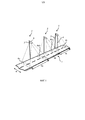
фиг. 1 иллюстрирует примерный схематичный вид в перспективе участка дороги с множеством осветительных систем согласно предпочтительному варианту осуществления настоящего изобретения;FIG. 1 illustrates an exemplary schematic perspective view of a road section with multiple lighting systems according to a preferred embodiment of the present invention;
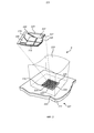
фиг. 2 - вид в перспективе одного из осветительных устройств предпочтительного варианта осуществления; иFIG. 2 is a perspective view of one of the lighting devices of a preferred embodiment; and
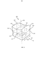
фиг. 3 иллюстрирует одно из оптических устройств предпочтительного варианта осуществления.FIG. 3 illustrates one of the optical devices of a preferred embodiment.
ПОДРОБНОЕ ОПИСАНИЕDETAILED DESCRIPTION
Далее настоящее изобретение будет описано более подробно со ссылкой на прилагаемые чертежи, в которых показаны предпочтительные в настоящее время варианты осуществления изобретения. Однако это изобретение может быть реализовано во многих разных формах, и его не следует рассматривать как ограниченное изложенными здесь вариантами осуществления; напротив, эти варианты осуществления обеспечены для законченности и полноты и полностью доводят объем изобретения до сведения специалиста в данной области техники. Аналогичные ссылочные позиции обозначают сходные элементы на всех чертежах.The present invention will now be described in more detail with reference to the accompanying drawings, in which presently preferred embodiments of the invention are shown. However, this invention can be implemented in many different forms, and should not be construed as limited to the embodiments set forth herein; on the contrary, these embodiments are provided for completeness and completeness and fully bring the scope of the invention to the attention of a person skilled in the art. Similar reference numerals denote similar elements throughout the drawings.
На чертежах и, в частности, на фиг. 1a представлен примерный схематичный вид в перспективе участка дороги 1 с множеством осветительных систем 2 согласно предпочтительному варианту осуществления изобретения. Каждая осветительная система 2 располагается на соответствующей опоре 3 освещения, причем длина каждой опоры 3 освещения адаптирована под имеющуюся реализацию. В данном случае, каждая опора 3 освещения имеет такую длину, что целевое расстояние 4 от оптического устройства до дороги равно приблизительно 8 метрам. Каждая осветительная система 2 освещает соответствующую уличную зону 5a, 5b, 5c, имеющую ширину W. Размеры каждой уличной зоны 5 может изменяться; в данном случае, однако, удлиненная форма является прямоугольником размерами, приблизительно 10 метров * 36 метров. Опоры 3 освещения расположены на расстоянии друг от друга и/или осветительные системы 2 выполнены с такой возможностью, что освещенные уличные зоны 5 могут немного перекрываться в зонах 6a, 6ab, 6bc, 6c перекрытия.In the drawings, and in particular in FIG. 1a is an exemplary schematic perspective view of a section of a
Для освещения соответствующих уличных зон 5, каждая осветительная система 2 содержит опорную конструкцию 7, на которой множество осветительных устройств 8 размещено в виде матрицы. Количество осветительных устройств 8 для каждой осветительной системы 2 может изменяться совместно с их расположением по отношению друг к другу, например в пределах от 4 до 64, в виде квадратной или прямоугольной матрицы. Для каждого осветительного устройства 8 осветительной системы 2, световой пучок, обусловленный одним осветительным устройством 8, аналогичен световому пучку, обусловленному другим осветительным устройством 8. Соответственно, благодаря тому, что каждая соответствующая осветительная система 2 содержит множество осветительных устройств 8, сгруппированных друг с другом и имеющих аналогичные световые пучки и аналогичные целевые расстояния 4, больше света, т.е. больший световой поток, концентрируется на соответствующей уличной зоне 5. Дополнительные подробности в отношении осветительного устройства 8, показанного на фиг. 1, будут рассмотрены со ссылкой на фиг. 2.To illuminate the respective street zones 5, each
На фиг. 2 показано, что осветительное устройство 8 содержит источник 220 света, размещенный на держателе 221. Одно осветительное устройство 8 проиллюстрировано только для простоты; однако в действительности, множество осветительных устройств 8 обеспечено на одном и том же держателе 221. Согласно показанному варианту осуществления, источник 220 света содержит множество СИД 228 - в данном случае 30 СИД, размещенных на площади 5 мм * 6 мм. Следует отметить, что согласно альтернативным реализациям, светоизлучающая сторона источника 220 света может принимать разные значения в пределах, например, 4-6 мм * 5-7 мм, и количество СИД может быть другим. Когда СИД 228 размещены очень близко друг к другу, обеспечивается компактное решение, позволяющее поддерживать повышенную светимость и/или позволяющее комбинировать больше СИД с разными характеристиками.In FIG. 2 shows that the
Держатель 221, в данном случае, представленный IMS (изолированной металлической подложкой), хотя согласно альтернативным вариантам осуществления, допустимы другие варианты, например, MCPCB (печатная плата на металлической основе) или PCB. Следует обратить внимание на то, что слои и/или компоненты, отличные от описанных далее, могут содержаться в или на держателе 221. В качестве нижнего слоя, проводящего тепло, исходящее от источника 220 света, держатель 221 содержит необязательный теплопроводящий металлический слой 222. Теплопроводящий металлический слой 222 может быть выполнен, например, из алюминия или меди, и иметь толщину, предпочтительно, в пределах от 0,5 мм до 3,2 мм. Поверх металлического слоя 222 может размещаться адгезивный слой (не показан), и поверх него - диэлектрический слой 223. Диэлектрический слой 223 представляет собой, например, электрически изолирующую полиамидную пленку. В необязательном порядке, диэлектрический слой 223 может содержать полимер с оксидом металла или оксидом алюминия, поверх которого предусмотрено тонкое изолирующее покрытие. Альтернативно, диэлектрический слой 223 может содержать керамику.The
Диэлектрический слой 223 имеет компонентную область 224, выполненную с возможностью приема компонентов, например источника 220 света. Компонентная область 224 имеет поверхность 225, на которой расположены проводящие пути 226. Проводящие пути 226 выполнены с возможностью переносить ток и электрические сигналы к/от источнику/а 220 света и/или другим/х компонентам/ов. Соответственно, проводящие пути 226 содержат контактные площадки, на которых множество СИД 228 расположено на диэлектрическом слое 223. В данном случае, проводящие пути 226, кроме того, содержат проводящие дорожки, ведущие к/от множеству/а СИД 228 (не показано). На фиг. 2, проводящие пути 226 формируются из общего медного слоя.The
Для улучшения рассеяния тепла от источника 220 света, область 227 распространения упомянутых проводящих путей 226 оптимизирована по отношению к пространству, доступному на поверхности 225 компонентной области 224. Благодаря увеличенной области 227 распространения проводящих путей 226, покрывается существенная часть поверхности 225 компонентной области 224, из-за чего, тепло, исходящее от источника 220 света, может распределяться по большей площади диэлектрического слоя 223. В данном случае, оптимизация равнозначна максимизации, благодаря чему, область 227 распространения охватывает как можно больше пространства, доступного на поверхности 225 компонентной области 224. Согласно показанному варианту осуществления, область распространения охватывает более 50% поверхности 225. Заметим, однако, что согласно альтернативным реализациям, область распространения может охватывать более 60%, или даже более 70%, поверхности 225.To improve heat dissipation from the
Кроме того, осветительное устройство 8 содержит оптическое устройство 229 для формирования светового пучка. Следует отметить, что показанная здесь компонентная область 224 полностью покрыта оптическим устройством 229; однако, согласно альтернативным вариантам осуществления, компонентная область 224 может выходить за пределы этого покрытия. Оптическое устройство 229 будет более подробно описано ниже со ссылкой на фиг. 3.In addition, the
На фиг. 3, показано, что примерное оптическое устройство 229 содержит линзу 330. Материалом линзы 330 в данном случае является ПММА, хотя для других реализаций линза 330 может быть выполнена из любого прозрачного окрашенного или бесцветного сформованного материала, например стекла, полиметакрилата или других пластмасс. Линза 330 имеет верхнюю секцию 331, выполненную с возможностью принимать свет, излучаемый источником 220 света, и нижнюю секцию 332, выполненную с возможностью позволять принятому свету покидать линзу 330. Линза 330, кроме того, имеет множество боковых секций 333 - в данном случае четыре - продолжающихся от верхней секции 331 к нижней секции 332, охватывающих линзу 330. Боковые секции 333 выполнены с возможностью отражать и преломлять падающие лучи принятого света. Сечение 334, в плоскости, перпендикулярной центральной оси 338, продолжающейся от верхней секции 331 к нижней секции 332, имеет форму многоугольника - в данном случае, прямоугольника 334. Прямоугольник 334 ориентирован в продольном направлении 335 и в поперечном направлении 336, которые перпендикулярны друг другу. Благодаря таким боковым секциям 333, линза 229 имеет компактную конструкцию, что позволяет более плотно размещать осветительные устройства 8, из-за чего, осветительная система 2 становится более компактной. Кроме того, линза 330 выполнена таким образом, что принятый свет выходит из линзы 330 в виде светового пучка, образованного в удлиненной форме на заранее определенном расстоянии от оптического устройства 229. Для реализации, показанной на фиг. 1, удлиненная форма представлена соответствующими уличными зонами 5a, 5b, 5c, и заранее определенное расстояние представлено целевым расстоянием 4.In FIG. 3, it is shown that an exemplary
В примерном варианте осуществления, линза 330 симметрична в квадрантах 337 в сечении 334 вдоль центральной оси 338. Кроме того, верхняя секция 331 имеет первую вогнутость в продольном направлении 335 и вторую вогнутость в поперечном направлении 336 - последняя больше первой. Нижняя секция 332, с другой стороны, расходится в продольном 335 и поперечном направлениях 336, причем в продольном направлении 335 расхождение больше, чем в поперечном направлении 336. Дополнительно, боковые секции 333 являются оптически плоскими, следовательно отсутствует шероховатость поверхности или микроструктуры, которые могут рассеивать падающий свет.In an exemplary embodiment, the
Таким образом, согласно предпочтительному описанному варианту осуществления, предусмотрено оптическое устройство 229, содержащее компактную линзу 330, обеспечивающее желаемое распределение 5a, 5a, 5b, 5c освещения. Кроме того, как показано, множество осветительных устройств 8 может располагаться более плотно, что позволяет осветительной системе 2 быть более компактной.Thus, according to a preferred embodiment described, an
В вышеописанных примерных вариантах осуществления настоящего изобретения, источники света содержат СИД. Однако возможно, и отвечает объему настоящего изобретения, использование разных типов источников света, например органических светодиодов (ОСИД), полимерных СИД (ПСИД), неорганических СИД, лазеров, или их комбинации, а также широкополосных СИД (с прямым или люминофорным преобразованием) и широкополосных СИД белого свечения (с люминофорным преобразованием). Кроме того, возможны также комбинации с другими источниками света, наподобие TL, CFL.In the above exemplary embodiments of the present invention, the light sources comprise LEDs. However, it is possible, and is within the scope of the present invention, to use different types of light sources, for example, organic light emitting diodes (OLEDs), polymer LEDs (PSID), inorganic LEDs, lasers, or a combination thereof, as well as broadband LEDs (with direct or phosphor conversion) and broadband White LED (with phosphor conversion). In addition, combinations with other light sources such as TL, CFL are also possible.
Дополнительно, следует обратить внимание на то, что любая комбинация цветов СИД может создавать гамму цветов, при этом СИД может обеспечивать красный, зеленый, синий, янтарный, белый, оранжевый, УФ или другие цвета. Различные варианты осуществления, представленные в этом описании изобретения, охватывают все возможные комбинации СИД, содержащиеся в световом модуле, что позволяет генерировать свет переменного цвета, интенсивности, насыщенности и цветовой температуры.Additionally, it should be noted that any combination of LED colors can create a gamut of colors, while LEDs can provide red, green, blue, amber, white, orange, UV, or other colors. The various embodiments presented in this specification cover all possible combinations of LEDs contained in a light module that allow the generation of light of varying color, intensity, saturation, and color temperature.
Следует отметить, что осветительная система дополнительно может содержать любое количество оптических и/или неоптических компонентов для обеспечения различных оптических эффектов. Эти компоненты могут включать в себя, но без ограничения, рассеиватели и пр., используемые в различных комбинациях для обеспечения желаемого эффекта.It should be noted that the lighting system may additionally contain any number of optical and / or non-optical components to provide various optical effects. These components may include, but are not limited to, diffusers, etc., used in various combinations to provide the desired effect.
Кроме того, хотя изобретение описано со ссылкой на конкретные примерные варианты его осуществления, специалисты в данной области техники могут предложить многие различные изменения, модификации и пр. Вариации раскрытых вариантов осуществления могут быть поняты и реализованы специалистом в данной области техники при практическом осуществлении заявленного изобретения, изучении чертежей, раскрытия и нижеследующей формулы изобретения. Кроме того, в формуле изобретения, слово "содержащий" не исключает наличия других элементов или этапов, и употребление названий элементов в единственном числе не исключает наличия их множества.In addition, although the invention is described with reference to specific exemplary options for its implementation, specialists in the art can offer many different changes, modifications, etc. Variations of the disclosed embodiments can be understood and implemented by a person skilled in the art in the practical implementation of the claimed invention, the study of the drawings, disclosure and the following claims. In addition, in the claims, the word “comprising” does not exclude the presence of other elements or steps, and the use of the names of the elements in the singular does not exclude the presence of a plurality of them.
Claims (18)
Applications Claiming Priority (3)
| Application Number | Priority Date | Filing Date | Title |
|---|---|---|---|
| EP11164927.3 | 2011-05-05 | ||
| EP11164927 | 2011-05-05 | ||
| PCT/IB2012/052106 WO2012150533A1 (en) | 2011-05-05 | 2012-04-27 | Optical device for forming a light beam |
Publications (2)
| Publication Number | Publication Date |
|---|---|
| RU2013153890A RU2013153890A (en) | 2015-06-10 |
| RU2612562C2 true RU2612562C2 (en) | 2017-03-09 |
Family
ID=46147542
Family Applications (1)
| Application Number | Title | Priority Date | Filing Date |
|---|---|---|---|
| RU2013153890A RU2612562C2 (en) | 2011-05-05 | 2012-04-27 | Optical device for generating light beam |
Country Status (6)
| Country | Link |
|---|---|
| US (1) | US9377176B2 (en) |
| EP (1) | EP2705397B1 (en) |
| JP (1) | JP6087904B2 (en) |
| CN (1) | CN103502872B (en) |
| RU (1) | RU2612562C2 (en) |
| WO (1) | WO2012150533A1 (en) |
Families Citing this family (4)
| Publication number | Priority date | Publication date | Assignee | Title |
|---|---|---|---|---|
| CN106340578A (en) * | 2015-07-09 | 2017-01-18 | 普因特工程有限公司 | Chip substrate with plating layer and chip package using same |
| JP6443515B2 (en) * | 2016-08-31 | 2018-12-26 | 日亜化学工業株式会社 | Optical member, light source device and irradiation system |
| JP6666873B2 (en) * | 2017-03-28 | 2020-03-18 | 株式会社朝日ラバー | Pseudo white LED device and silicone cap |
| CN111556946B (en) * | 2018-01-02 | 2022-11-11 | 昕诺飞控股有限公司 | Luminaire comprising surface tiles and a lighting device |
Citations (4)
| Publication number | Priority date | Publication date | Assignee | Title |
|---|---|---|---|---|
| US20060018010A1 (en) * | 2004-07-20 | 2006-01-26 | Simon Blumel | Optical element |
| RU95793U1 (en) * | 2009-12-29 | 2010-07-10 | Открытое акционерное общество "Завод ПРОТОН-МИЭТ" | LIGHT PLANE ENERGY-SAVING |
| US20110007513A1 (en) * | 2009-07-10 | 2011-01-13 | Fu Zhun Precision Industry (Shen Zhen) Co., Ltd. | Led module |
| US20110096533A1 (en) * | 2009-10-27 | 2011-04-28 | William Sekela | Refractive optics to provide uniform illumination in a display case |
Family Cites Families (16)
| Publication number | Priority date | Publication date | Assignee | Title |
|---|---|---|---|---|
| TWI261654B (en) | 2004-12-29 | 2006-09-11 | Ind Tech Res Inst | Lens and LED with uniform light emitted applying the lens |
| US20070152674A1 (en) | 2005-12-02 | 2007-07-05 | Hubbell David A | Thermal Energy Management of Electronic Devices |
| DE102006035635A1 (en) | 2006-07-31 | 2008-02-07 | Osram Opto Semiconductors Gmbh | lighting arrangement |
| US7607792B2 (en) | 2006-12-22 | 2009-10-27 | Hong Kong Applieed Science and Technology Research Institute Co. LTd. | Light-emitting devices and lens therefor |
| CN101657678B (en) | 2007-04-05 | 2014-02-26 | 皇家飞利浦电子股份有限公司 | Light-beam shaper |
| US7674019B2 (en) | 2007-08-11 | 2010-03-09 | Anthony, Inc. | Free-form lenses for rectangular illumination zones |
| GB0717802D0 (en) | 2007-09-12 | 2007-10-24 | Photonstar Led Ltd | Electrically isolated vertical light emitting diode structure |
| US20100012354A1 (en) | 2008-07-14 | 2010-01-21 | Logan Brook Hedin | Thermally conductive polymer based printed circuit board |
| CN201434331Y (en) | 2008-08-16 | 2010-03-31 | 上海三思电子工程有限公司 | Lens for LED street lamp |
| TWM364824U (en) | 2008-09-19 | 2009-09-11 | Genius Electronic Optical Co Ltd | Optical lens body of bilateral asymmetry polarization illumination |
| US8277085B2 (en) | 2008-10-06 | 2012-10-02 | Light Prescriptions Innovators, Llc | Compact LED downlight with cuspated flux-redistribution lens |
| US8215814B2 (en) * | 2008-11-21 | 2012-07-10 | Dbm Reflex Enterprises Inc. | Solid state optical illumination apparatus |
| CN201487808U (en) | 2009-06-09 | 2010-05-26 | 深圳市斯派克光电科技有限公司 | Two-time light distribution lens of LED street lamp |
| CN102054925B (en) * | 2009-10-29 | 2013-12-11 | 富准精密工业(深圳)有限公司 | Light emitting diode module |
| CN101696784A (en) | 2009-11-12 | 2010-04-21 | 东莞勤上光电股份有限公司 | Asymmetrical secondary optical lens |
| US8267550B2 (en) * | 2010-06-09 | 2012-09-18 | Chin-Wen Wang | LED lamp for easy assembly and fixation |
-
2012
- 2012-04-27 WO PCT/IB2012/052106 patent/WO2012150533A1/en active Application Filing
- 2012-04-27 JP JP2014508902A patent/JP6087904B2/en not_active Expired - Fee Related
- 2012-04-27 EP EP12722879.9A patent/EP2705397B1/en active Active
- 2012-04-27 RU RU2013153890A patent/RU2612562C2/en active
- 2012-04-27 CN CN201280021865.5A patent/CN103502872B/en not_active Expired - Fee Related
- 2012-04-27 US US14/113,588 patent/US9377176B2/en active Active
Patent Citations (4)
| Publication number | Priority date | Publication date | Assignee | Title |
|---|---|---|---|---|
| US20060018010A1 (en) * | 2004-07-20 | 2006-01-26 | Simon Blumel | Optical element |
| US20110007513A1 (en) * | 2009-07-10 | 2011-01-13 | Fu Zhun Precision Industry (Shen Zhen) Co., Ltd. | Led module |
| US20110096533A1 (en) * | 2009-10-27 | 2011-04-28 | William Sekela | Refractive optics to provide uniform illumination in a display case |
| RU95793U1 (en) * | 2009-12-29 | 2010-07-10 | Открытое акционерное общество "Завод ПРОТОН-МИЭТ" | LIGHT PLANE ENERGY-SAVING |
Also Published As
| Publication number | Publication date |
|---|---|
| CN103502872B (en) | 2016-09-14 |
| EP2705397B1 (en) | 2019-06-26 |
| JP6087904B2 (en) | 2017-03-01 |
| US20140049959A1 (en) | 2014-02-20 |
| WO2012150533A1 (en) | 2012-11-08 |
| EP2705397A1 (en) | 2014-03-12 |
| CN103502872A (en) | 2014-01-08 |
| US9377176B2 (en) | 2016-06-28 |
| JP2014514614A (en) | 2014-06-19 |
| RU2013153890A (en) | 2015-06-10 |
Similar Documents
| Publication | Publication Date | Title |
|---|---|---|
| US7267461B2 (en) | Directly viewable luminaire | |
| US9091420B2 (en) | Illumination apparatus | |
| JP2008108674A (en) | Led lighting fixture | |
| RU99592U1 (en) | LED SPOTLIGHT | |
| JP6238163B2 (en) | Lighting device and lighting fixture | |
| US20090021931A1 (en) | Led luminaire for generating substantially uniform illumination on a target plane | |
| CN102016395A (en) | Optical system for batwing distribution | |
| JP2014216322A (en) | Lighting device | |
| JP2011124207A (en) | Wide-angle led illuminating device | |
| RU2612562C2 (en) | Optical device for generating light beam | |
| JP2011103275A (en) | Light emitting diode lighting fixture | |
| CN101963288A (en) | Light-emitting structure capable of improving light-emitting efficiency and controlling emergent angle and manufacture method thereof | |
| KR20150117007A (en) | Lens optical system for luminous intensity distribution control of led groups, and led groups lighting included the same | |
| WO2014011665A1 (en) | Light unit with light output pattern synthesized from multiple light sources and modular refractors | |
| KR200451022Y1 (en) | Led lamp structure for improving radiation heat and illumination efficiency | |
| CN201526828U (en) | Light emitting diode lamp structure with integrally formed appearance | |
| RU151491U1 (en) | LED PROJECTOR WITH ADJUSTABLE KSS (OPTIONS) | |
| JP2013045921A (en) | Light emitting device and lighting device | |
| TWM443271U (en) | Optical element and light source module with the optical element | |
| KR101694997B1 (en) | Lens for a lighting unit | |
| KR20130031475A (en) | Lighting device | |
| KR101730142B1 (en) | Lens for a lighting unit | |
| KR101816311B1 (en) | Lighting device | |
| TW201205004A (en) | LED illuminating device | |
| WO2009116704A1 (en) | Illuminating apparatus using light emitting diode |
Legal Events
| Date | Code | Title | Description |
|---|---|---|---|
| HZ9A | Changing address for correspondence with an applicant |