RU2611230C2 - Metal cutting machine tool - Google Patents
Metal cutting machine tool Download PDFInfo
- Publication number
- RU2611230C2 RU2611230C2 RU2015103841A RU2015103841A RU2611230C2 RU 2611230 C2 RU2611230 C2 RU 2611230C2 RU 2015103841 A RU2015103841 A RU 2015103841A RU 2015103841 A RU2015103841 A RU 2015103841A RU 2611230 C2 RU2611230 C2 RU 2611230C2
- Authority
- RU
- Russia
- Prior art keywords
- satellite
- tool holder
- tool
- cutting machine
- support
- Prior art date
Links
Images
Classifications
-
- B—PERFORMING OPERATIONS; TRANSPORTING
- B23—MACHINE TOOLS; METAL-WORKING NOT OTHERWISE PROVIDED FOR
- B23Q—DETAILS, COMPONENTS, OR ACCESSORIES FOR MACHINE TOOLS, e.g. ARRANGEMENTS FOR COPYING OR CONTROLLING; MACHINE TOOLS IN GENERAL CHARACTERISED BY THE CONSTRUCTION OF PARTICULAR DETAILS OR COMPONENTS; COMBINATIONS OR ASSOCIATIONS OF METAL-WORKING MACHINES, NOT DIRECTED TO A PARTICULAR RESULT
- B23Q39/00—Metal-working machines incorporating a plurality of sub-assemblies, each capable of performing a metal-working operation
- B23Q39/02—Metal-working machines incorporating a plurality of sub-assemblies, each capable of performing a metal-working operation the sub-assemblies being capable of being brought to act at a single operating station
- B23Q39/028—Metal-working machines incorporating a plurality of sub-assemblies, each capable of performing a metal-working operation the sub-assemblies being capable of being brought to act at a single operating station with a plurality of workholder per toolhead in operating position
-
- B—PERFORMING OPERATIONS; TRANSPORTING
- B23—MACHINE TOOLS; METAL-WORKING NOT OTHERWISE PROVIDED FOR
- B23P—METAL-WORKING NOT OTHERWISE PROVIDED FOR; COMBINED OPERATIONS; UNIVERSAL MACHINE TOOLS
- B23P23/00—Machines or arrangements of machines for performing specified combinations of different metal-working operations not covered by a single other subclass
- B23P23/02—Machine tools for performing different machining operations
-
- B—PERFORMING OPERATIONS; TRANSPORTING
- B23—MACHINE TOOLS; METAL-WORKING NOT OTHERWISE PROVIDED FOR
- B23B—TURNING; BORING
- B23B39/00—General-purpose boring or drilling machines or devices; Sets of boring and/or drilling machines
- B23B39/16—Drilling machines with a plurality of working-spindles; Drilling automatons
- B23B39/18—Setting work or tool carrier along a straight index line
-
- B—PERFORMING OPERATIONS; TRANSPORTING
- B23—MACHINE TOOLS; METAL-WORKING NOT OTHERWISE PROVIDED FOR
- B23P—METAL-WORKING NOT OTHERWISE PROVIDED FOR; COMBINED OPERATIONS; UNIVERSAL MACHINE TOOLS
- B23P17/00—Metal-working operations, not covered by a single other subclass or another group in this subclass
- B23P17/02—Single metal-working processes; Machines or apparatus therefor
-
- B—PERFORMING OPERATIONS; TRANSPORTING
- B23—MACHINE TOOLS; METAL-WORKING NOT OTHERWISE PROVIDED FOR
- B23Q—DETAILS, COMPONENTS, OR ACCESSORIES FOR MACHINE TOOLS, e.g. ARRANGEMENTS FOR COPYING OR CONTROLLING; MACHINE TOOLS IN GENERAL CHARACTERISED BY THE CONSTRUCTION OF PARTICULAR DETAILS OR COMPONENTS; COMBINATIONS OR ASSOCIATIONS OF METAL-WORKING MACHINES, NOT DIRECTED TO A PARTICULAR RESULT
- B23Q39/00—Metal-working machines incorporating a plurality of sub-assemblies, each capable of performing a metal-working operation
- B23Q39/02—Metal-working machines incorporating a plurality of sub-assemblies, each capable of performing a metal-working operation the sub-assemblies being capable of being brought to act at a single operating station
- B23Q39/021—Metal-working machines incorporating a plurality of sub-assemblies, each capable of performing a metal-working operation the sub-assemblies being capable of being brought to act at a single operating station with a plurality of toolheads per workholder, whereby the toolhead is a main spindle, a multispindle, a revolver or the like
- B23Q39/022—Metal-working machines incorporating a plurality of sub-assemblies, each capable of performing a metal-working operation the sub-assemblies being capable of being brought to act at a single operating station with a plurality of toolheads per workholder, whereby the toolhead is a main spindle, a multispindle, a revolver or the like with same working direction of toolheads on same workholder
- B23Q39/024—Metal-working machines incorporating a plurality of sub-assemblies, each capable of performing a metal-working operation the sub-assemblies being capable of being brought to act at a single operating station with a plurality of toolheads per workholder, whereby the toolhead is a main spindle, a multispindle, a revolver or the like with same working direction of toolheads on same workholder consecutive working of toolheads
-
- B—PERFORMING OPERATIONS; TRANSPORTING
- B23—MACHINE TOOLS; METAL-WORKING NOT OTHERWISE PROVIDED FOR
- B23P—METAL-WORKING NOT OTHERWISE PROVIDED FOR; COMBINED OPERATIONS; UNIVERSAL MACHINE TOOLS
- B23P2700/00—Indexing scheme relating to the articles being treated, e.g. manufactured, repaired, assembled, connected or other operations covered in the subgroups
- B23P2700/04—Connecting rods
-
- B—PERFORMING OPERATIONS; TRANSPORTING
- B23—MACHINE TOOLS; METAL-WORKING NOT OTHERWISE PROVIDED FOR
- B23P—METAL-WORKING NOT OTHERWISE PROVIDED FOR; COMBINED OPERATIONS; UNIVERSAL MACHINE TOOLS
- B23P2700/00—Indexing scheme relating to the articles being treated, e.g. manufactured, repaired, assembled, connected or other operations covered in the subgroups
- B23P2700/50—Other automobile vehicle parts, i.e. manufactured in assembly lines
-
- B—PERFORMING OPERATIONS; TRANSPORTING
- B23—MACHINE TOOLS; METAL-WORKING NOT OTHERWISE PROVIDED FOR
- B23Q—DETAILS, COMPONENTS, OR ACCESSORIES FOR MACHINE TOOLS, e.g. ARRANGEMENTS FOR COPYING OR CONTROLLING; MACHINE TOOLS IN GENERAL CHARACTERISED BY THE CONSTRUCTION OF PARTICULAR DETAILS OR COMPONENTS; COMBINATIONS OR ASSOCIATIONS OF METAL-WORKING MACHINES, NOT DIRECTED TO A PARTICULAR RESULT
- B23Q39/00—Metal-working machines incorporating a plurality of sub-assemblies, each capable of performing a metal-working operation
- B23Q2039/006—Machines with multi-spindles
-
- Y—GENERAL TAGGING OF NEW TECHNOLOGICAL DEVELOPMENTS; GENERAL TAGGING OF CROSS-SECTIONAL TECHNOLOGIES SPANNING OVER SEVERAL SECTIONS OF THE IPC; TECHNICAL SUBJECTS COVERED BY FORMER USPC CROSS-REFERENCE ART COLLECTIONS [XRACs] AND DIGESTS
- Y10—TECHNICAL SUBJECTS COVERED BY FORMER USPC
- Y10T—TECHNICAL SUBJECTS COVERED BY FORMER US CLASSIFICATION
- Y10T29/00—Metal working
- Y10T29/49—Method of mechanical manufacture
- Y10T29/49229—Prime mover or fluid pump making
- Y10T29/49288—Connecting rod making
-
- Y—GENERAL TAGGING OF NEW TECHNOLOGICAL DEVELOPMENTS; GENERAL TAGGING OF CROSS-SECTIONAL TECHNOLOGIES SPANNING OVER SEVERAL SECTIONS OF THE IPC; TECHNICAL SUBJECTS COVERED BY FORMER USPC CROSS-REFERENCE ART COLLECTIONS [XRACs] AND DIGESTS
- Y10—TECHNICAL SUBJECTS COVERED BY FORMER USPC
- Y10T—TECHNICAL SUBJECTS COVERED BY FORMER US CLASSIFICATION
- Y10T29/00—Metal working
- Y10T29/51—Plural diverse manufacturing apparatus including means for metal shaping or assembling
- Y10T29/5104—Type of machine
- Y10T29/5105—Drill press
- Y10T29/5107—Drilling and other
-
- Y—GENERAL TAGGING OF NEW TECHNOLOGICAL DEVELOPMENTS; GENERAL TAGGING OF CROSS-SECTIONAL TECHNOLOGIES SPANNING OVER SEVERAL SECTIONS OF THE IPC; TECHNICAL SUBJECTS COVERED BY FORMER USPC CROSS-REFERENCE ART COLLECTIONS [XRACs] AND DIGESTS
- Y10—TECHNICAL SUBJECTS COVERED BY FORMER USPC
- Y10T—TECHNICAL SUBJECTS COVERED BY FORMER US CLASSIFICATION
- Y10T409/00—Gear cutting, milling, or planing
- Y10T409/30—Milling
- Y10T409/30784—Milling including means to adustably position cutter
- Y10T409/307952—Linear adjustment
- Y10T409/308344—Plural cutters
-
- Y—GENERAL TAGGING OF NEW TECHNOLOGICAL DEVELOPMENTS; GENERAL TAGGING OF CROSS-SECTIONAL TECHNOLOGIES SPANNING OVER SEVERAL SECTIONS OF THE IPC; TECHNICAL SUBJECTS COVERED BY FORMER USPC CROSS-REFERENCE ART COLLECTIONS [XRACs] AND DIGESTS
- Y10—TECHNICAL SUBJECTS COVERED BY FORMER USPC
- Y10T—TECHNICAL SUBJECTS COVERED BY FORMER US CLASSIFICATION
- Y10T409/00—Gear cutting, milling, or planing
- Y10T409/30—Milling
- Y10T409/30784—Milling including means to adustably position cutter
- Y10T409/308568—Plural cutters
Abstract
Description
ОБЛАСТЬ ТЕХНИКИ, К КОТОРОЙ ОТНОСИТСЯ НАСТОЯЩЕЕ ИЗОБРЕТЕНИЕFIELD OF THE INVENTION
Настоящее изобретение относится к области металлорежущих станков.The present invention relates to the field of machine tools.
УРОВЕНЬ ТЕХНИКИBACKGROUND
Металлорежущие станки используют для механической обработки обрабатываемых деталей, таких как обрабатываемые детали из металла, для обеспечения их требуемой формой и конфигурацией, например, путем сверления или растачивания отверстий в обрабатываемых деталях и/или путем механической обработки кромок для придания им требуемой, например скошенной, формы. Например, механическая обработка шатуна для присоединения поршня к коленчатому валу поршневого возвратно-поступательного двигателя включает в себя несколько разных операций, которые могут выполняться на одном металлорежущем станке или последовательно на разных металлорежущих станках, которые могут быть разными, или которые могут иметь одинаковую базовую конструкцию, но являться оснащенными разными инструментами, приспособленными для выполнения конкретных операций. Например, механическая обработка шатуна такого типа, как правило, включает некоторые или все из следующих этапов:Metal-cutting machines are used for machining machined parts, such as machined metal parts, to provide them with the desired shape and configuration, for example, by drilling or boring holes in the machined parts and / or by machining the edges to give them the desired, for example beveled, shape . For example, machining a connecting rod to attach a piston to the crankshaft of a reciprocating engine includes several different operations that can be performed on a single metal cutting machine or sequentially on different metal cutting machines, which may be different, or which may have the same basic design, but be equipped with different tools, adapted to perform specific operations. For example, machining a connecting rod of this type typically involves some or all of the following steps:
- черновое шлифование поверхностей заготовки;- rough grinding of the surfaces of the workpiece;
- черновое растачивание отверстия под поршневой палец и отверстия под шатунную шейку;- rough boring holes for the piston pin and holes for the connecting rod neck;
- механическая обработка болтовых отверстий и посадочных поверхностей;- machining of bolt holes and seating surfaces;
- раскалывание шатуна (стержня и головки) и соединение болтами;- splitting of the connecting rod (rod and head) and bolting;
- чистовое шлифование поверхностей;- fine grinding of surfaces;
- фрезерование трапеции и получистовая обработка отверстия под шатунную шейку;- milling of the trapezoid and semi-finishing processing of the hole for the connecting rod neck;
- чистовое растачивание отверстия под поршневой палец и отверстия под шатунную шейку.- Fine boring holes for the piston pin and holes for the connecting rod neck.
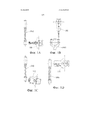
Например, на фиг. 1A-1D показано, как некоторые из этих операций можно осуществить на заготовке 1000 шатуна путем использования разных инструментов 100, 101, 102, 103, которые могут быть присоединены к соответствующим шпиндельным бабкам, подлежащим приведению в движение шпинделем для вращательного движения вокруг, например, горизонтальной оси Z (на фиг. 1 не проиллюстрирована) традиционным образом. Например, на фиг. 1А показано растачивание отверстия под поршневой палец первым инструментом 100, на фиг. 1B показано механическую обработку болтовых отверстий с использованием второго инструмента 101, на фиг. 1С показано фрезерование трапецеидального торца заготовки с использованием третьего инструмента 102, и на фиг. 1D показано растачивание отверстия под шатунную шейку с использованием четвертого инструмента 103. Все эти этапы можно осуществлять при помощи одного металлорежущего станка, в котором разные инструменты установлены одновременно или последовательно. Разумеется, также можно осуществлять разные этапы с использованием разных металлорежущих станков.For example, in FIG. 1A-1D show how some of these operations can be carried out on the
Станки этого типа обычно оснащены резцедержателем любого вида, в котором инструменты можно менять в зависимости от задачи, которая должна выполняться станком в определенное время или в определенном промежутке времени. В данном описании, термин «инструмент» следует толковать в общем смысле, и он может, но не обязан, включать связанную шпиндельную бабку.Machines of this type are usually equipped with a tool holder of any kind, in which the tools can be changed depending on the task that the machine must perform at a specific time or in a certain period of time. In this description, the term “tool” should be interpreted in a general sense, and it may, but is not required to, include a connected headstock.
Металлорежущие станки для выполнения таких операций механической обработки, как сверление и фрезерование, например, путем вращательного движения инструмента, например, для профилирования и растачивания шатунов для поршневых возвратно-поступательных двигателей хорошо известны из уровня техники, и поэтому описание действия привода инструмента зажимного механизма для инструментов не считается необходимым, так как специалист осознает, как конструировать оборудование этого вида, и так как соответствующие устройства являются серийно выпускаемыми.Metal-cutting machines for performing machining operations such as drilling and milling, for example, by rotating the tool, for example, for profiling and boring rods for reciprocating reciprocating engines, are well known in the art, and therefore, a description of the operation of a tool drive of a clamping mechanism for tools is not considered necessary, as the specialist is aware of how to construct equipment of this type, and since the corresponding devices are serially OSCAL.
Металлорежущими станками обычно управляют посредством числовых команд, и механическую обработку на металлорежущих станках с вращающимися инструментами выполняют путем вырабатывания управляемого относительного перемещения между обрабатываемой деталью и соответствующим инструментом. Например, известно создание станка с одним или несколькими неподвижными инструментами для перемещения одной или нескольких обрабатываемых деталей, таких как обрабатываемая деталь или заготовка, из которой нужно получить шатун, относительно неподвижного инструмента, например, параллельно горизонтальной оси Z (ось Z может представлять собой ось, вокруг которой вращается инструмент, или ось, параллельную этой оси), параллельно оси X, которая может представлять собой горизонтальную ось, перпендикулярную оси Z, и параллельно оси Y, которая может представлять собой вертикальную ось.Metal cutting machines are usually controlled by numerical commands, and machining on metal cutting machines with rotating tools is performed by generating controlled relative movement between the workpiece and the corresponding tool. For example, it is known to create a machine tool with one or more stationary tools for moving one or more workpieces, such as the workpiece or workpiece from which you want to get a connecting rod, relative to a stationary tool, for example, parallel to the horizontal Z axis (the Z axis can be an axis, around which the tool rotates, or an axis parallel to this axis), parallel to the X axis, which can be a horizontal axis perpendicular to the Z axis, and parallel to the Y axis, which can T represents a vertical axis.
В патенте США US-B-7442154 раскрыт металлорежущий станок, содержащий станину, инструменты в которой могут быть установлены в резцедержателях, которые могут представлять собой инструментальные шпиндели. Разные инструменты можно применять на разных высотах станины. Предусмотрен спутник для обрабатываемых деталей, который может перемещать обрабатываемую деталь в трех разных, ортогональных направлениях, т.е. в вертикальном направлении «Y» и в двух перпендикулярных горизонтальных направлениях, именуемых «X» и «Z». Спутник для обрабатываемых деталей также может вращаться вокруг оси «Z».In US patent US-B-7442154 disclosed a metal cutting machine containing a bed, tools in which can be installed in tool holders, which can be tool spindles. Different tools can be used at different heights of the bed. A satellite is provided for the workpiece, which can move the workpiece in three different orthogonal directions, i.e. in the vertical direction "Y" and in two perpendicular horizontal directions, referred to as "X" and "Z". The workpiece satellite can also rotate around the Z axis.
Другой пример станка этого вида известен из международной патентной заявки WO-A-2008/089751, в которой раскрыт металлорежущий станок на основе сетчатой конструкции станины, в которой можно закреплять инструменты. Этот металлорежущий станок содержит спутник для обрабатываемых деталей, выполненный с возможностью перемещения по направляющей X-Y-Z.Another example of a machine of this kind is known from international patent application WO-A-2008/089751, in which a metal cutting machine is disclosed based on a mesh frame structure in which tools can be fixed. This metal cutting machine contains a satellite for the workpiece, made with the possibility of movement along the guide X-Y-Z.
В обоих этих станках резцедержатели расположены свешивающимся образом, ср.. например, фиг. 1 патента US-B-7442154 и фиг. 12 заявки WO-A-2008/089751. Можно полагать, что это может, по меньшей мере в некоторых случаях, представлять трудность, например, тогда, когда на резцедержатель действуют существенные усилия, что, например, может происходить при механической обработке шатунов. Поэтому следует уделять внимание прочности и жесткости спутника для обрабатываемых деталей (в том числе конструкции для его направления), то есть, например, прочности и жесткости пиноли, показанной в заявке WO-A-2008/089751.In both of these machines, toolholders are arranged in a hanging manner, cf .. for example, FIG. 1 of US-B-7442154 and FIG. 12 applications WO-A-2008/089751. It can be assumed that this can be difficult, at least in some cases, for example, when significant efforts are applied to the tool post, which, for example, can occur during the machining of connecting rods. Therefore, attention should be paid to the strength and stiffness of the satellite for the workpiece (including the design for its direction), that is, for example, the strength and stiffness of the pintles shown in the application WO-A-2008/089751.
Также наблюдается, что при замене инструментов в станке согласно патенту US-А-7442154, оператор должен иметь доступ в пространство внутри станины, удерживающей инструменты. Сходным образом, при замене инструментов в металлорежущем станке, известном из заявки WO-A-2008/089751, оператору будет необходимо иметь доступ к пространству внутри сетчатой станины. Однако это пространство является ограниченным, среди прочего, из-за присутствия пиноли и инструментов. Сходные трудности оказываются относящимися к доступу к спутнику для обрабатываемых деталей при замене обрабатываемых деталей или при замене самого спутника для обрабатываемых деталей, или его частей.It is also observed that when replacing tools in the machine according to US-A-7442154, the operator must have access to the space inside the bed holding the tools. Similarly, when replacing tools in a metal cutting machine known from WO-A-2008/089751, the operator will need to have access to the space inside the mesh bed. However, this space is limited, inter alia, due to the presence of pintles and tools. Similar difficulties turn out to be related to access to a satellite for workpieces when replacing workpieces or when replacing a satellite for workpieces or parts thereof.
По меньшей мере некоторые их этих трудностей могут стать еще более серьезными, когда инструменты и/или спутник для обрабатываемых деталей размещены высоко. В станках, известных из патента US-A-7442154 и заявки WO-A-2008/089751, эксплуатационную гибкость можно улучшить путем включения в станину инструментов разных видов и распределения этих инструментов в вертикальном направлении станины. Это, однако, предполагает, что по меньшей мере некоторые из инструментов могут быть размещены на значительной высоте над поверхностью, на которой оператор будет стоять при манипулировании, например, инструментами в ходе процесса технического обслуживания или замены инструментов, и/или что по меньшей мере некоторые из инструментов могут быть размещены очень низко. В обоих случаях при манипулировании инструментами оператор должен принимать эргономически неблагоприятное положение.At least some of these difficulties can become even more serious when instruments and / or companions for workpieces are placed high. In machines known from US-A-7442154 and WO-A-2008/089751, operational flexibility can be improved by incorporating different types of tools into the frame and distributing these tools in the vertical direction of the frame. This, however, implies that at least some of the tools can be placed at a considerable height above the surface on which the operator will stand when handling, for example, tools during the maintenance process or tool replacement, and / or that at least some of tools can be placed very low. In both cases, when handling tools, the operator must take an ergonomically unfavorable position.
В патенте Германии DE-A-102008014779 раскрыт металлорежущий станок, в котором резцедержатель выполнен с возможностью поперечного перемещения между положением, в котором он находится перед спутником для обрабатываемых деталей, и положением, в котором он может принимать инструменты из инструментального магазина.German Patent DE-A-102008014779 discloses a metal-cutting machine in which the tool holder is capable of lateral movement between the position in which it is in front of the satellite for the workpieces and the position in which it can receive tools from the tool magazine.
Часто является желательным повышение производительности этого вида оборудования. Это можно осуществить, например, путем повышения емкости резцедержателей для увеличения таким образом количества инструментов, переносимых каждым резцедержателем, например, путем добавления большего количества инструментов в каждый ряд или путем увеличения количества рядов, посредством чего увеличивается вертикальная протяженность резцедержателей. Однако это не всегда желательно, например, по эргономическим причинам.It is often desirable to increase the productivity of this type of equipment. This can be done, for example, by increasing the capacity of the toolholders to thus increase the number of tools carried by each tool holder, for example, by adding more tools to each row or by increasing the number of rows, thereby increasing the vertical length of the tool holders. However, this is not always desirable, for example, for ergonomic reasons.
Часто используют решения с вращательным переводом: несколько спутников для обрабатываемых деталей располагают на вращающейся опоре, и вокруг этой опоры располагают соответствующее количество резцедержателей, обращенных к соответствующим спутникам для обрабатываемых деталей. Опора вращается так, что каждый спутник для обрабатываемых деталей переводится из обращения к одному резцедержателю к обращению к следующему резцедержателю, и инструменты, переносимые этими резцедержателями, приводятся в действие для осуществления различных операций на обращенных к ним обрабатываемых деталях. Такое расположение может предусматривать высокую производительность, однако обладает недостатками в том, что касается эргономики и эксплуатационной гибкости. Например, когда механической обработке подлежит обрабатываемая деталь нового типа, необходимо заменять весь набор спутников для обрабатываемых деталей. Доступ к резцедержателям для замены инструментов также может быть осложнен, поскольку доступ может быть возможен только с одной стороны, что может представлять собой серьезный недостаток с эргономической точки зрения. Таким образом, изменение конфигурации металлорежущего станка для нового вида изделия может быть сложным и трудоемким.Rotational translation solutions are often used: several satellites for the workpieces are placed on a rotating support, and around this support an appropriate number of toolholders are located facing the respective satellites for the workpiece. The support rotates so that each satellite for machined parts is transferred from going to one tool holder to going to the next tool holder, and the tools carried by these tool holders are actuated to perform various operations on the machined parts facing them. Such an arrangement may provide for high performance, but it has disadvantages in terms of ergonomics and operational flexibility. For example, when a new type of workpiece is to be machined, it is necessary to replace the entire set of satellites for the workpiece. Access to toolholders for changing tools can also be difficult, as access can only be possible on one side, which can be a serious ergonomic disadvantage. Thus, changing the configuration of a metal cutting machine for a new type of product can be complex and time-consuming.
Кроме того, у станков этого вида существует склонность к накоплению металлической стружки на инструментах и/или платформе под инструментами, что может оказывать отрицательное воздействие на работу оборудования.In addition, for machines of this type, there is a tendency to accumulate metal chips on tools and / or the platform under the tools, which can have a negative impact on the operation of the equipment.
ОПИСАНИЕ НАСТОЯЩЕГО ИЗОБРЕТЕНИЯDESCRIPTION OF THE PRESENT INVENTION
В одном аспекте настоящее изобретение относится к металлорежущему станку, содержащему:In one aspect, the present invention relates to a metal cutting machine, comprising:
по меньшей мере два узла спутника для обрабатываемых деталей (каждый из которых содержит или состоит из, например, конструктивно устойчивого, прочного и/или жесткого суппорта), каждый из которых содержит спутник для удерживания по меньшей мере одной обрабатываемой детали (узел спутника для обрабатываемых деталей может, например, представлять собой конструкцию, такую как металлическая конструкция, расположенная для обеспечения достаточной устойчивости и жесткости во избежание, по существу, нежелательного перемещения спутника для обрабатываемых деталей и обрабатываемых деталей в ходе механической обработки);at least two satellite nodes for workpieces (each of which contains or consists of, for example, structurally stable, durable and / or rigid caliper), each of which contains a satellite for holding at least one workpiece (satellite node for workpieces may, for example, be a structure, such as a metal structure, located to provide sufficient stability and stiffness to prevent essentially undesirable satellite movement for processing Pipeline components and workpieces during machining);
по меньшей мере две опоры для упомянутых узлов спутника, при этом каждый узел спутника установлен на соответствующую одну из указанных опор узлов спутника с возможностью горизонтального перемещения по ней в первом направлении, которое параллельно горизонтальной оси Z;at least two supports for said satellite nodes, wherein each satellite node is mounted on a corresponding one of said satellite node supports with the possibility of horizontal movement along it in the first direction, which is parallel to the horizontal Z axis;
по меньшей мере первый резцедержатель, выполненный с возможностью удерживания по меньшей мере одного инструмента для механической обработки по меньшей мере одной обрабатываемой детали посредством вращения указанного инструмента вокруг оси, параллельной указанной оси Z (этот резцедержатель, как правило, может объединять один или несколько шпинделей или шпиндельных бабок, приспособленных для вращения одного или нескольких инструментов);at least a first tool holder capable of holding at least one tool for machining at least one workpiece by rotating said tool around an axis parallel to said Z axis (this tool holder can typically combine one or more spindles or spindles tailstock adapted to rotate one or more tools);
опору резцедержателей, при этом указанный первый резцедержатель установлен на указанной опоре резцедержателей с возможностью горизонтального перемещения по ней во втором направлении, которое параллельно горизонтальной оси X, расположенной перпендикулярно к указанной оси Z (то есть, например, узлы спутников для обрабатываемых деталей со спутниками для обрабатываемых деталей можно считать подвижными назад и вперед по опорам спутников для обрабатываемых деталей, в то время как резцедержатель можно считать подвижным в поперечном направлении по опоре резцедержателей);the tool holder support, wherein said first tool holder is mounted on said tool holder support with the possibility of horizontal movement along it in the second direction, which is parallel to the horizontal X axis located perpendicular to the specified Z axis (i.e., for example, satellite nodes for machined parts with satellites for machined parts can be considered moving back and forth along the satellite supports for the workpieces, while the tool holder can be considered movable in the transverse direction eeniya on the support of toolholders);
при этом указанный первый резцедержатель выполнен с возможностью перемещения по указанной опоре резцедержателей в указанном втором направлении между по меньшей мере одним рабочим положением, в котором указанный первый резцедержатель обращен к одному из указанных узлов спутника (таким образом, чтобы при работе станка, один или несколько инструментов, переносимых указанным первым резцедержателем, могли взаимодействовать с одной или несколькими обрабатываемыми деталями, переносимыми соответствующим спутником для обрабатываемых деталей, для механической обработки этих обрабатываемых деталей путем перемещения спутника для обрабатываемых деталей и/или инструмента, или инструментов), и по меньшей мере одним нерабочим положением, в котором указанный первый резцедержатель не обращен ни к одному из указанных узлов спутника (термин «между» не следует толковать как предполагающий, что указанное по меньшей мере одно рабочее положение и указанное по меньшей мере одно нерабочее положение обязательно являются конечными положениями, но лишь предполагает, что первый резцедержатель можно переместить из нерабочего положения в рабочее положение и наоборот; например, в некоторых вариантах осуществления настоящего изобретения может иметься по меньшей мере два рабочих положения, разделенных по меньшей мере одним нерабочим положением, и, таким образом, резцедержатель можно перемещать из одного рабочего положения в нерабочее положение, а затем продолжать перемещение в следующее рабочее положение),wherein said first tool holder is arranged to move along said support of toolholders in said second direction between at least one operating position in which said first tool holder faces one of said satellite nodes (so that, when the machine is operating, one or more tools carried by the indicated first tool post could interact with one or more workpieces carried by the corresponding satellite for workpieces her, for machining these workpieces by moving a satellite for the workpieces and / or tool, or tools), and at least one inoperative position in which the specified first tool post does not face any of the specified satellite nodes (the term “between” should not be construed as suggesting that the at least one working position and the at least one non-working position are necessarily end positions, but only suggests that the first tool post The body can be moved from a non-working position to a working position and vice versa; for example, in some embodiments of the present invention, there may be at least two operating positions separated by at least one idle position, and thus the tool holder can be moved from one operating position to the idle position, and then continue to move to the next operating position) ,
при этом станок снабжен вторым резцедержателем, выполненным с возможностью удерживания по меньшей мере одного инструмента для механической обработки по меньшей мере одной обрабатываемой детали посредством вращения указанного инструмента вокруг оси, параллельной упомянутой оси Z;wherein the machine is equipped with a second tool holder configured to hold at least one tool for machining at least one workpiece by rotating said tool around an axis parallel to said Z axis;
при этом указанный второй резцедержатель установлен на указанной опоре резцедержателей с возможностью горизонтального перемещения в упомянутом втором направлении между рабочим положением, в котором указанный второй резцедержатель обращен к одному из указанных узлов спутника, и нерабочим положением, в котором указанный второй резцедержатель не обращен ни к одному из указанных узлов спутника.wherein said second tool holder is mounted on said tool holder support with the possibility of horizontal movement in said second direction between a working position in which said second tool holder is facing one of said satellite nodes and an idle position in which said second tool holder is not facing any of specified satellite nodes.
Таким образом, когда первый резцедержатель не обращен к узлу спутника для обрабатываемых деталей, но, в основном, поперечно смещен относительно указанных узлов спутника для обрабатываемых деталей, также легко заменять инструменты и на переднем конце первого резцедержателя (то есть на том конце, который обращен к соответствующему узлу спутника для обрабатываемых деталей, когда первый резцедержатель находится в рабочем положении). То есть оператор может осуществлять доступ к инструментам спереди без необходимости во вхождении или доступе в пространство между узлом спутника для обрабатываемых деталей и резцедержателем. Таким образом, такое расположение предусматривает эргономичность и эксплуатационную гибкость. Также, тот факт, что резцедержатель выполнен с возможностью перемещения в поперечном направлении, дополнительно предусматривает эксплуатационную гибкость при производстве, так как может быть предусмотрено несколько резцедержателей, которые выборочно могут приводиться в рабочее положение в зависимости от конкретных операций механической обработки, которые следует осуществлять. С другой стороны, использование по меньшей мере двух узлов спутника для обрабатываемых деталей улучшает эксплуатационную гибкость и производительность: например, один резцедержатель может последовательно взаимодействовать с одним из указанных узлов спутника для обрабатываемых деталей и с другим из указанных узлов спутника для обрабатываемых деталей, посредством чего можно выполнять загрузку обрабатываемыми деталями одного из указанных узлов спутника для обрабатываемых деталей, например, в то время как инструменты резцедержателя механически обрабатывают обрабатываемые детали, загруженные в спутник для обрабатываемых деталей другого узла спутника для обрабатываемых деталей. Также, или в качестве альтернативы, на обрабатываемых деталях, установленных в разных узлах спутников для обрабатываемых деталей, можно выполнять разные операции, и обрабатываемые детали могут передаваться из одного из узлов спутника для обрабатываемых деталей в другой из указанных узлов спутника для обрабатываемых деталей. Может быть предусмотрен один или несколько роботов или манипуляторов для передачи обрабатываемых деталей из одного из узлов спутника для обрабатываемых деталей в другой узел и/или для загрузки и разгрузки обрабатываемых деталей на узлы или из узлов спутника для обрабатываемых деталей, например, для разгрузки, а затем загрузки одного из указанных узлов спутника для обрабатываемых деталей, в то время как инструменты резцедержателя действуют на обрабатываемые детали в другом узле спутника для обрабатываемых деталей. Таким образом, можно оптимизировать производительность. Также, при достаточном количестве резцедержателей и узлов спутника для обрабатываемых деталей можно значительно уменьшить риск (или последствия) простоев, вызванных трудностями с одним единственным резцедержателем или узлом спутника для обрабатываемых деталей. Вышеописанную идею можно реализовать множеством различных способов в зависимости от конкретных потребностей каждого потенциального пользователя. Тот факт, что как резцедержатель, так и узлы спутника для обрабатываемых деталей выполнены с возможностью перемещения по соответствующим опорам, предусматривает устойчивость и жесткость. Это может быть особенно желательно в связи с механической обработкой шатунов, так как механическая обработка этого вида предполагает, что на обрабатываемые детали действуют очень большие усилия, а производственные допуски часто являются небольшими. Также часто небольшой является конструктивная устойчивость обрабатываемых деталей этого вида. Таким образом, важными являются устойчивость и жесткость компонентов, вовлекаемых в механическую обработку, в том числе инструментов, резцедержателей и спутника для обрабатываемых деталей.Thus, when the first tool holder is not facing the satellite assembly for the workpiece, but is basically laterally offset from the indicated satellite assemblies for the workpiece, it is also easy to replace the tools at the front end of the first tool holder (i.e., at the end that faces corresponding satellite assembly for workpieces when the first tool post is in working position). That is, the operator can access the tools from the front without the need to enter or access the space between the satellite node for the workpiece and the tool post. Thus, this arrangement provides ergonomics and operational flexibility. Also, the fact that the tool holder is movable in the transverse direction additionally provides for operational flexibility in production, since several tool holders can be provided that can be selectively brought into operation depending on the specific machining operations to be performed. On the other hand, the use of at least two satellite nodes for workpieces improves operational flexibility and productivity: for example, one tool holder can sequentially interact with one of these satellite nodes for workpieces and with the other of these satellite nodes for workpieces, whereby perform loading of the workpieces of one of the specified satellite nodes for the workpieces, for example, while the tool holder tools m mechanically processed workpieces loaded into a satellite to another satellite machined parts for assembly of workpieces. Also, or alternatively, on the workpieces installed in different satellite nodes for the workpieces, different operations can be performed, and the workpieces can be transferred from one of the satellite nodes for the workpiece to another of the specified satellite nodes for the workpiece. One or more robots or manipulators can be provided for transferring workpieces from one of the satellite nodes for workpieces to another node and / or for loading and unloading workpieces to nodes or from satellite nodes for workpieces, for example, for unloading, and then loading one of these satellite nodes for the workpiece, while the tool holder tools act on the workpiece in another satellite node for the workpiece. In this way, performance can be optimized. Also, with a sufficient number of tool holders and satellite assemblies for workpieces, the risk (or consequences) of downtime caused by difficulties with a single tool holder or satellite assembly for machined parts can be significantly reduced. The above idea can be implemented in many different ways, depending on the specific needs of each potential user. The fact that both the tool holder and the satellite nodes for the workpieces are made with the ability to move along the respective supports, provides stability and rigidity. This may be especially desirable in connection with the machining of the connecting rods, since machining of this type assumes that very large forces act on the machined parts, and manufacturing tolerances are often small. Also often small is the structural stability of the machined parts of this type. Thus, the stability and rigidity of the components involved in machining, including tools, tool holders and a satellite for machined parts, are important.
При использовании двух (или более) отдельных резцедержателей, которые могут выборочно перемещать между их рабочим положением (или положениями) и их нерабочим положением (или положениями), можно получить некоторые дополнительные преимущества. Большую эксплуатационную гибкость и легкость замены инструментов предусматривает не только нерабочее положение, но и тот факт, что наличие двух (или более) резцедержателей предполагает, что один из них можно использовать для механической обработки, в то время как на другом (других) может осуществляться техническое обслуживание и/или замена инструментов. Также использование нескольких резцедержателей, таких как два или более резцедержателя, предусматривает возможность наличия относительно широкого разнообразия готовых к использованию (то есть установленных на соответствующем резцедержателе) инструментов без любой необходимости в расположении инструментов в широком интервале в вертикальном направлении. Например, полагая, что каждый резцедержатель содержит, например, N (например, 2) рядов инструментов, каждый из которых содержит, например, М (например, 4) инструмента, первый и второй резцедержатели совместно могут удерживать 2×N×M (например, 16) инструментов. Таким образом, например, в любой момент времени два резцедержателя совместно могут удерживать два разных набора из N×M инструментов или четыре разных набора из N×M/2 инструментов, распределенных только по N рядов (например, по двум (2) рядам) в вертикальном направлении. То есть по причине поперечного перемещения резцедержателей, в разных резцедержателях «в готовности к употреблению» можно установить широкое разнообразие инструментов при поддержании в то же время инструментов в пределах относительно короткой протяженности в вертикальном направлении. Это может являться преимущественным, так как это предполагает, что все инструменты можно расположить на высоте, при которой манипулирование инструментами, например, замена инструментов, может осуществляться оператором в эргономичных условиях, например, без необходимости в избыточном наклоне вперед и/или без необходимости в подъеме на лестницы и т.п.By using two (or more) separate toolholders that can selectively move between their working position (or positions) and their inactive position (or positions), some additional advantages can be obtained. Greater operational flexibility and ease of replacing tools is provided not only by the inoperative position, but also by the fact that the presence of two (or more) tool holders suggests that one of them can be used for machining, while the other (others) can carry out technical Maintenance and / or replacement of tools. Also, the use of several tool holders, such as two or more tool holders, makes it possible to have a relatively wide variety of ready-to-use tools (i.e. mounted on an appropriate tool holder) without any need for arranging the tools in a wide interval in the vertical direction. For example, assuming that each tool holder contains, for example, N (for example, 2) tool rows, each of which contains, for example, M (for example, 4) tools, the first and second tool holders together can hold 2 × N × M (for example, 16) tools. Thus, for example, at any time, two tool holders together can hold two different sets of N × M tools or four different sets of N × M / 2 tools distributed only in N rows (for example, in two (2) rows) in vertical direction. That is, due to the transverse movement of the toolholders, in different toolholders "ready to use" you can set a wide variety of tools while maintaining tools at the same time within a relatively short length in the vertical direction. This may be advantageous, since it assumes that all the tools can be positioned at a height at which the manipulation of the tools, for example, replacing the tools, can be carried out by the operator in ergonomic conditions, for example, without the need for an excessive forward bend and / or without the need for lifting to stairs, etc.
Первый резцедержатель может быть выполнен с возможностью перемещения между указанным рабочим положением, в котором указанный первый резцедержатель обращен к одному из указанных узлов спутника, и, по меньшей мере, другим рабочим положением, в котором указанный первый резцедержатель обращен к другому из указанных узлов спутника. То есть один и тот же резцедержатель можно использовать для последовательного действия на обрабатываемые детали в двух разных узлах спутника для обрабатываемых деталей, и дополнительно его можно перемещать в нерабочее положение тогда, когда, например, существует потребность в замене одного или нескольких инструментов.The first tool holder can be arranged to move between the specified operating position, in which the specified first tool holder is facing one of the indicated satellite nodes, and at least the other working position, in which the specified first tool holder is facing the other of the specified satellite nodes. That is, the same tool holder can be used to sequentially act on the workpieces in two different satellite nodes for the workpieces, and additionally it can be moved to the off position when, for example, there is a need to replace one or more tools.
В одном из вариантов исполнения изобретения, опоры узлов спутника расположены со стороны соответствующих боковых частей упомянутой опоры резцедержателей, при этом упомянутое нерабочее положение расположено в центральной части упомянутой опоры резцедержателей, а рабочие положения расположены по боковым частям упомянутой опоры резцедержателей. Таким образом, в ходе работы станка один набор инструментов можно заменить другим набором инструментов путем простого передвижения резцедержателя в центральную часть опоры резцедержателей. Например, после завершения некоторого цикла механической обработки резцедержатель можно передвинуть в сторону в его нерабочее положение. Эта конфигурация, как было обнаружено, является практичной и позволяет гибко использовать резцедержатели, в то время как общий объем необходимого пространства является довольно ограниченным. Вся длина опоры резцедержателей при использовании одного или двух резцедержателей может быть ограничена приблизительно утроенной шириной каждого резцедержателя для вмещения таким образом двух рабочих положений и нерабочего положения.In one embodiment of the invention, the support of the satellite nodes are located on the side of the respective lateral parts of the said support of the tool holders, while the said inactive position is located in the central part of the said support of the tool holders, and the working positions are located on the side parts of the said support of the tool holders. Thus, during the operation of the machine, one set of tools can be replaced with another set of tools by simply moving the tool holder to the central part of the tool holder support. For example, after completing some machining cycle, the tool holder can be moved sideways to its inoperative position. This configuration has been found to be practical and allows the flexible use of toolholders, while the total amount of space required is quite limited. The entire length of the toolholder support when using one or two toolholders can be limited to approximately triple the width of each tool holder in order to accommodate two operating positions and a non-working position.
В одном из вариантов исполнения изобретения, опоры узлов спутника и опора резцедержателей расположены вместе с образованием U-образной или F-образной конфигурации в горизонтальной плоскости.In one embodiment of the invention, the support of the satellite nodes and the support of the toolholders are located together with the formation of a U-shaped or F-shaped configuration in the horizontal plane.
В альтернативном варианте опоры узлов спутника размещены напротив соответствующих промежуточных частей упомянутой опоры резцедержателей, расположенных между ее центральной частью и двумя боковыми частями, при этом рабочие положения расположены на указанных промежуточных частях, а нерабочие положения расположены на упомянутых боковых частях и центральной части. Это может обеспечивать дополнительное улучшение эксплуатационной гибкости; например, если имеется два резцедержателя, то каждый из них может взаимодействовать с каждым из узлов спутников для обрабатываемых деталей путем перемещения другого резцедержателя в соответствующую боковую или оконечную часть опоры резцедержателей всякий раз, когда это необходимо.In an alternative embodiment, the support of the satellite nodes is located opposite the respective intermediate parts of the said tool holder support located between its central part and two side parts, while the operating positions are located on these intermediate parts, and the non-working positions are located on the said side parts and the central part. This may provide further improvement in operational flexibility; for example, if there are two tool holders, then each of them can interact with each of the satellite nodes for the workpiece by moving the other tool holders to the corresponding side or end of the tool holder support whenever necessary.
В одном из вариантов исполнения изобретения, металлорежущий станок снабжен по меньшей мере третьим узлом спутника, содержащим третий спутник для удерживания по меньшей мере одной обрабатываемой детали, и по меньшей мере третьей опорой для упомянутого узла спутника, при этом указанный третий узел спутника установлен на указанной третьей опоре с возможностью горизонтального перемещения по ней в указанном первом направлении.In one embodiment of the invention, the cutting machine is provided with at least a third satellite assembly comprising a third satellite for holding at least one workpiece, and at least a third support for said satellite assembly, wherein said third satellite assembly is mounted on said third support with the possibility of horizontal movement along it in the specified first direction.
Использование третьего узла спутника для обрабатываемых деталей может способствовать еще дополнительному увеличению производительности и эксплуатационной гибкости.The use of a third satellite assembly for workpieces can further increase productivity and operational flexibility.
В одном из вариантов исполнения изобретения, опоры узлов спутника расположены напротив двух боковых частей и одной центральной части упомянутой опоры резцедержателей, при этом, по меньшей мере, некоторые из нерабочих положений расположены на промежуточных частях упомянутой опоры резцедержателей, расположенных между ее центральной частью и двумя боковыми частями, а рабочие положения расположены на боковых частях и центральной части упомянутой опоры резцедержателей.In one embodiment of the invention, the support of the satellite nodes are located opposite two side parts and one central part of the said tool holder support, while at least some of the inoperative positions are located on the intermediate parts of the tool holder support located between its central part and two side parts, and operating positions are located on the lateral parts and the Central part of the mentioned support toolholders.
В одном из вариантов исполнения изобретения, металлорежущий станок снабжен но меньшей мере третьим резцедержателем, выполненным с возможностью перемещения в указанном втором направлении между по меньшей мере одним рабочим положением и по меньшей мере одним нерабочим положением.In one embodiment of the invention, the metal cutting machine is equipped with at least a third tool holder, configured to move in the specified second direction between at least one working position and at least one idle position.
В одном из вариантов исполнения изобретения, упомянутые опоры узлов спутника и опора резцедержателей расположены вместе с образованием Е-образной конфигурации в горизонтальной плоскости. Очевидно, металлорежущий станок может содержать дополнительные опоры спутника для обрабатываемых деталей, расположенные вдоль опоры резцедержателей.In one embodiment of the invention, said satellite node support and tool holder support are located together with the formation of an E-shaped configuration in a horizontal plane. Obviously, the metal cutting machine may contain additional satellite supports for the workpieces located along the support of the toolholders.
В одном возможном осуществлении настоящего изобретения все инструменты при установке в соответствующем резцедержателе размещены на высоте не менее чем 0,7 м, предпочтительно, не менее чем 1,1 м, и не более чем 1,8 м, предпочтительно, не более чем 1,5 м. Таким образом, оператор может управлять инструментами, в то же время принимая удобное и эргономически правильное положение без необходимости в подъеме на лестницы и т.п.In one possible implementation of the present invention, all tools when installed in an appropriate tool holder are placed at a height of not less than 0.7 m, preferably not less than 1.1 m, and not more than 1.8 m, preferably not more than 1, 5 m. Thus, the operator can control the tools, at the same time taking a comfortable and ergonomically correct position without the need for climbing stairs, etc.
В одном из вариантов исполнения изобретения, указанный первый резцедержатель содержит N рядов инструментов, при этом 1≤N≤5, предпочтительно N равно 2, 3 или 4. При использовании довольно небольшого количества рядов, можно содержать все инструменты на высоте, допускающей легкость при манипулировании инструментами оператором.In one embodiment of the invention, said first tool holder comprises N rows of tools, with 1≤N≤5, preferably N is 2, 3 or 4. When using a fairly small number of rows, you can contain all the tools at a height that allows ease of handling tools by the operator.
В одном из вариантов исполнения изобретения, спутник для обрабатываемых деталей установлен на упомянутом узле спутника с возможностью перемещения в вертикальном направлении, то есть параллельно вертикальной оси Y. Таким образом, при помощи описанного до сих пор расположения обеспечивается относительное перемещение между инструментами и обрабатываемыми деталями по осям Z, X и Y.In one embodiment of the invention, a satellite for the workpieces is mounted on the satellite assembly with the possibility of moving in the vertical direction, that is, parallel to the vertical axis Y. Thus, using the arrangement described so far, relative axial movement between the tools and the workpiece is ensured Z, X and Y.
Очевидно, из объема настоящего изобретения не исключаются дополнительные степени свободы, такие как, например, вращение спутника для обрабатываемых деталей вокруг оси, как, например, вокруг оси. параллельной оси Z.Obviously, additional degrees of freedom are not excluded from the scope of the present invention, such as, for example, rotating a satellite for workpieces around an axis, such as, for example, around an axis. parallel to the z axis.
В одном из вариантов исполнения изобретения, опоры узлов спутника и опора резцедержателей приспособлены для поддержки узла спутника и резцедержателей снизу. Иногда может быть предпочтительно, чтобы ни один из резцедержателей или узел спутника для обрабатываемых деталей не свешивался с надземных опор; использование простых наземных опор, размещенных на полу, может быть предпочтительно, например, по причине простоты установки.In one embodiment of the invention, the support of the satellite assemblies and the support of the toolholders are adapted to support the satellite assembly and toolholders from below. Sometimes it may be preferable that none of the toolholders or satellite assembly for the workpieces should hang from overhead supports; the use of simple ground supports placed on the floor may be preferable, for example, because of the ease of installation.
В одном из вариантов исполнения изобретения, опоры узлов спутника и опора резцедержателей имеют высоту не более чем 1,1 м, предпочтительно, не более чем 0,6 м. Таким образом, резцедержатели могут быть размещены относительно низко для облегчения доступа к инструментам.In one embodiment of the invention, the supports of the satellite nodes and the support of the toolholders have a height of not more than 1.1 m, preferably not more than 0.6 m. Thus, the toolholders can be placed relatively low to facilitate access to tools.
В одном из вариантов исполнения изобретения, каждый спутник для обрабатываемых деталей приспособлен для удерживания нескольких обрабатываемых деталей.In one embodiment of the invention, each satellite for workpieces is adapted to hold several workpieces.
В другом варианте исполнения изобретения, каждый спутник для обрабатываемых деталей приспособлен для удерживания 4-8 обрабатываемых деталей.In another embodiment of the invention, each satellite for machined parts is adapted to hold 4-8 machined parts.
В одном из вариантов исполнения изобретения, металлорежущий станок выполнен с возможностью механической обработки шатунов для двигателя с возвратно-поступательным движением поршня, предпочтительно двигателя автомобиля или грузовика. Механическая обработка шатунов для двигателя с возвратно-поступательным движением поршня, такого как двигатель внутреннего сгорания автомобиля или грузовика, представляет собой задачу, включающую в себя некоторые специфические соображения, для которой традиционно использовались довольно специфические станки. Металлорежущий станок согласно настоящему изобретению может включать преимущества в выражении устойчивости и жесткости, как было разъяснено выше.In one embodiment of the invention, the metal cutting machine is capable of machining the connecting rods for a reciprocating piston engine, preferably a motor vehicle or truck. The machining of connecting rods for a reciprocating piston engine, such as an internal combustion engine of a car or truck, is a task that includes some specific considerations for which fairly specific machines have traditionally been used. A metal cutting machine according to the present invention may include advantages in terms of stability and rigidity, as explained above.
В другом аспекте настоящее изобретение относится к металлорежущему станку для механической обработки шатунов для двигателя с возвратно-поступательным движением поршня, преимущественно двигателя автомобиля или грузовика, содержащему:In another aspect, the present invention relates to a metal cutting machine for machining connecting rods for a reciprocating piston engine, preferably a car or truck engine, comprising:
по меньшей мере два узла спутника для обрабатываемых шатунов, каждый из которых содержит спутник для удерживания по меньшей мере одного обрабатываемого шатуна;at least two satellite nodes for the processed connecting rods, each of which contains a satellite for holding at least one processed connecting rod;
по меньшей мере две опоры для упомянутых узлов спутника, при этом каждый узел спутника установлен на соответствующую одну из указанных опор узлов спутника с возможностью горизонтального перемещения по ней в первом направлении, которое параллельно горизонтальной оси Z;at least two supports for said satellite nodes, wherein each satellite node is mounted on a corresponding one of said satellite node supports with the possibility of horizontal movement along it in the first direction, which is parallel to the horizontal Z axis;
по меньшей мере первый резцедержатель, выполненный с возможностью удерживания по меньшей мере одного инструмента для механической обработки по меньшей мере одного обрабатываемого шатуна посредством вращения указанного инструмента вокруг оси, параллельной упомянутой оси Z;at least a first tool holder adapted to hold at least one tool for machining at least one connecting rod by rotating said tool around an axis parallel to said Z axis;
опору резцедержателей, при этом указанный первый резцедержатель установлен на указанной опоре резцедержателей с возможностью горизонтального перемещения по ней во втором направлении, которое параллельно горизонтальной оси X, расположенной перпендикулярно к упомянутой оси Z;a tool holder support, wherein said first tool holder is mounted on said tool holder support with the possibility of horizontal movement along it in the second direction, which is parallel to the horizontal axis X located perpendicular to said Z axis;
при этом указанный первый резцедержатель выполнен с возможностью перемещения по указанной опоре резцедержателей в указанном втором направлении между по меньшей мере одним рабочим положением, в котором указанный первый резцедержатель обращен к одному из указанных узлов спутника, и по меньшей мере одним нерабочим положением, в котором указанный первый резцедержатель не обращен ни к одному из узлов спутника.wherein said first tool holder is arranged to move along said support of toolholders in said second direction between at least one operating position in which said first tool holder is facing one of said satellite nodes and at least one inoperative position in which said first the tool holder is not facing any of the satellite nodes.
В одном из вариантов исполнения изобретения, каждый спутник приспособлен для удерживания нескольких обрабатываемых шатунов.In one embodiment of the invention, each satellite is adapted to hold several processing rods.
В другом варианте исполнения изобретения, каждый спутник приспособлен для удерживания 4-8 обрабатываемых шатунов.In another embodiment of the invention, each satellite is adapted to hold 4-8 machined rods.
КРАТКОЕ ОПИСАНИЕ ГРАФИЧЕСКИХ МАТЕРИАЛОВBRIEF DESCRIPTION OF GRAPHIC MATERIALS
Для выполнения описания и с целью обеспечения лучшего понимания настоящего изобретения предусмотрен набор графических материалов. Указанные графические материалы образуют неотъемлемую часть описания и иллюстрируют один из вариантов осуществления изобретения, который не следует толковать как ограничивающий объем изобретения, но лишь как один из примеров того, как может быть воплощено изобретение. Графические материалы содержат следующие фигуры.To complete the description and in order to provide a better understanding of the present invention, a set of graphic materials is provided. These graphic materials form an integral part of the description and illustrate one embodiment of the invention, which should not be construed as limiting the scope of the invention, but only as one example of how the invention can be embodied. Graphic materials contain the following figures.
На фиг. 1A-1D схематически проиллюстрированы некоторые операции, которые могут быть осуществлены при механической обработке шатуна исходя из заготовки шатуна с использованием разных инструментов.In FIG. 1A-1D schematically illustrate some of the operations that can be carried out by machining the connecting rod based on the workpiece of the connecting rod using different tools.
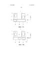
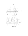
На фиг. 2A-2D представлены схематические виды сверху, иллюстрирующие различные возможные схемы расположения металлорежущего станка в соответствии с настоящим изобретением.In FIG. 2A-2D are schematic plan views illustrating various possible layouts of a metal cutting machine in accordance with the present invention.
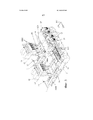
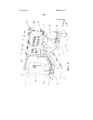
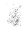
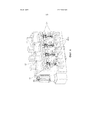
На фиг. 3-5 представлены схематические перспективные виды металлорежущего станка согласно одному из вариантов осуществления настоящего изобретения.In FIG. 3-5 are schematic perspective views of a metal cutting machine according to one embodiment of the present invention.
На фиг. 6 представлен схематический перспективный вид спутника для обрабатываемых деталей, который может быть использован в одном из вариантов осуществления настоящего изобретения.In FIG. 6 is a schematic perspective view of a satellite for workpieces that can be used in one embodiment of the present invention.
ОПИСАНИЕ ОДНОГО ИЗ ВАРИАНТОВ ОСУЩЕСТВЛЕНИЯ НАСТОЯЩЕГО ИЗОБРЕТЕНИЯDESCRIPTION OF ONE OF THE EMBODIMENTS OF THE PRESENT INVENTION
На фиг. 2А схематически проиллюстрирована схема расположения металлорежущего станка в соответствии с первым вариантом осуществления настоящего изобретения. Здесь две опоры 1 спутников для обрабатываемых деталей проходят параллельно в направлении соответствующих концов опоры 2 резцедержателей в U-образной конфигурации. Узел 11 спутника для обрабатываемых деталей установлен на каждой из указанных опор спутников для обрабатываемых деталей для перемещения в направлении Z. Металлорежущий станок содержит один единственный резцедержатель 21, выполненный с возможностью перемещения по опоре резцедержателей в направлении X, перпендикулярном направлению Z. Можно наблюдать, как этот резцедержатель можно перемещать между двумя рабочими положениями А, в которых резцедержатель обращен к соответствующему узлу спутника для обрабатываемых деталей (для обеспечения возможности действовать на соответствующие обрабатываемые детали), и промежуточным нерабочим положением, где оператор может легко перемещать инструменты и осуществлять другие задачи по техническому обслуживанию, относящиеся к этому резцедержателю. Таким образом, резцедержатель можно переводить между разными рабочими положениями для действия на обрабатываемые детали в одном из узлов спутников для обрабатываемых деталей, в то же время как в другом узле спутника для обрабатываемых деталей имеет место, например, разгрузка и/или загрузка обрабатываемых деталей.In FIG. 2A schematically illustrates an arrangement of a metal cutting machine according to a first embodiment of the present invention. Here, two satellite supports 1 for the workpieces pass in parallel in the direction of the corresponding ends of the
На фиг. 2B проиллюстрировано расположение, отличающееся от такового на фиг. 2А тем, что имеется второй резцедержатель 22. При таком расположении можно улучшить производительность, так как механическая обработка обрабатываемых деталей может иметь место одновременно в двух узлах спутников для обрабатываемых деталей.In FIG. 2B illustrates an arrangement different from that of FIG. 2A by the fact that there is a
На фиг. 2С проиллюстрировано альтернативное расположение, в котором опора 2 резцедержателей проходит с обеспечением нерабочих положений B в боковых или оконечных частях, а также в центральной части опоры резцедержателей, и рабочих положений А в двух промежуточных частях. Это предполагает преимущество по меньшей мере в выражении эксплуатационной гибкости в сравнении с вариантом осуществления настоящего изобретения по фиг. 2B: в варианте осуществления изобретения по фиг. 2С каждый из двух резцедержателей 21, 22 можно располагать перед каждым одним из двух узлов 11 спутников для обрабатываемых деталей. Это представляет собой преимущество не только в выражении эксплуатационной гибкости, но также позволяет продолжать работу на обоих узлах спутников для обрабатываемых деталей в случае отказа в одном из узлов спутников для обрабатываемых деталей: дефектный узел спутника для обрабатываемых деталей просто передвигают в нерабочее положение В на конце опоры резцедержателей 2, а оставшийся резцедержатель затем передвигают между двумя рабочими положениями А.In FIG. 2C illustrates an alternative arrangement in which the
На фиг. 2D проиллюстрирован дополнительный вариант осуществления со схемой расположения Е-образной формы. Здесь имеется три узла 11 спутников для обрабатываемых деталей на соответствующих опорах 1 спутников для обрабатываемых деталей и три резцедержателя 21, 22, 23. Это может дополнительно улучшать производительность.In FIG. 2D illustrates an additional embodiment with an E-shaped arrangement. There are three
Очевидно, существуют три бесконечные альтернативы. Например, вариант осуществления изобретения по фиг. 2D можно модифицировать путем удаления одного из узлов 11 спутников для обрабатываемых деталей и опор 1 с обеспечением схемы расположения F-образной формы. Или опору резцедержателей можно дополнительно расширить с обеспечением дополнительных нерабочих положений на ее концах. Всякий раз, когда это желательно, можно добавлять дополнительные опоры спутников для обрабатываемых деталей.Obviously, there are three endless alternatives. For example, the embodiment of FIG. 2D can be modified by removing one of the
Один возможный вариант осуществления настоящего изобретения в соответствии со схемой расположения U-образной формы по фиг. 2B более подробно показан на фиг. 3-5. Металлорежущий станок содержит два узла 11 спутников для обрабатываемых деталей, на каждом из которых установлен спутник 12 для обрабатываемых деталей с возможностью его перемещения параллельно вертикальной оси Y по направляющим рельсам 13. Это вертикальное перемещение спутника для обрабатываемых деталей по направляющим рельсам 13 может быть достигнуто традиционными средствами, такими как система 20 привода с серводвигателем, которой можно управлять с помощью компьютера 50 металлорежущего станка (схематически проиллюстрированного на фиг. 5). Посредством вертикального перемещения спутник 12 для обрабатываемых деталей можно располагать на требуемой высоте для приема обрабатываемых деталей из устройства подачи (не проиллюстрировано) для доставки механически обработанных обрабатываемых деталей, для расположения обрабатываемых деталей на правильной высоте с целью взаимодействия с инструментами для механической обработки и для перемещения обрабатываемых деталей вертикально в ходе механической обработки.One possible embodiment of the present invention in accordance with the U-shaped arrangement of FIG. 2B is shown in more detail in FIG. 3-5. The metal cutting machine contains two
Каждый узел 11 спутника для обрабатываемых деталей представляет собой суппорт, рассчитанный на устойчивость и жесткость с возможностью поддержания обрабатываемых деталей в их точном положении в ходе взаимодействия с инструментами. Каждый суппорт опирается на соответствующую опору 1 спутника для обрабатываемых деталей, содержащую горизонтальные рельсы 14 (ср. фиг. 4), проходящие вдоль или параллельно горизонтальной оси Z. Узел или суппорт спутника для обрабатываемых деталей опирается и направляется направляющими рельсами для горизонтального перемещения параллельно указанной оси Z. Металлорежущий станок включает системы 15 привода, такие как системы привода с серводвигателем, для перемещения узлов 11 спутников для обрабатываемых деталей по направляющим рельсам 14 управляемым образом, например, под управлением компьютера 50. Посредством этого горизонтального перемещения узлы спутников для обрабатываемых деталей можно, например, разместить в определенном положении для загрузки/разгрузки обрабатываемых деталей, разместить в некотором положении для запуска механической обработки (путем взаимодействия инструментов с обрабатываемыми деталями) и переместить горизонтально в ходе механической обработки для перемещения обрабатываемых деталей относительно инструментов.Each
В этом варианте осуществления каждый узел 11 или суппорт спутника для обрабатываемых деталей покоится на соответствующей опоре 1 спутника для обрабатываемых деталей, то есть он может не свешиваться с нее. Это расположение может, таким образом, способствовать улучшению устойчивости, жесткости, а также облегчить установку металлорежущего станка в сравнении с установками, например, со свешивающейся пинолью. Жесткость может быть особенно важна тогда, когда обрабатываемые детали представляют собой, например, заготовки для шатунов, так как допуски являются небольшими, в то время как конструктивная жесткость заготовки часто является относительно низкой.In this embodiment, each
Металлорежущий станок дополнительно содержит два резцедержателя 21 и 22, опирающиеся на опору 2 резцедержателей, проходящую вдоль или параллельно горизонтальной оси X, перпендикулярной оси Z. Опора 2 резцедержателей расположена на одном из концов опор 1 спутников для обрабатываемых деталей, пересекающихся с опорой 2 резцедержателей приблизительно на соответствующих концах опоры 2 резцедержателей, посредством чего опора резцедержателей и опора спутника для обрабатываемых деталей совместно образуют U-образную схему расположения при рассмотрении сверху. Опора 2 резцедержателей содержит на ее верхней поверхности две горизонтальные направляющие рельсы 16, на которые опираются два резцедержателя 21 и 22, и по которым они направляются параллельно указанной оси X, управляемым образом приводимые в движение системой 17 привода, например системой привода с серводвигателем, работой которой можно управлять с помощью компьютера 50.The metal cutting machine additionally contains two
Первый резцедержатель 21 выполнен с возможностью перемещения по опоре 2 резцедержателей между рабочим положением (в котором он обращен к одному из узлов 11 спутников для обрабатываемых деталей, и в котором инструменты, установленные в резцедержателе, могут, таким образом, действовать на заготовки обрабатываемых деталей, установленные в спутнике 12 для обрабатываемых деталей) и нерабочим положением, в котором он не обращен к узлу спутника для обрабатываемых деталей, но является поперечно смещенным по отношению к указанному узлу спутника для обрабатываемых деталей. На фиг. 3-5 первый резцедержатель 21 находится в нерабочем положении. Таким образом, в этом положении оператор может манипулировать инструментами, например, осматривать или заменять инструменты 102 и 103, установленные в первом резцедержателе 21 без необходимости во вхождении в пространство между узлом 11 спутника для обрабатываемых деталей и резцедержателем 21. Таким образом, как проиллюстрировано на фиг. 3-5, манипулировать инструментами легко. Можно наблюдать, как первый резцедержатель 21, находясь в нерабочем положении, находится в центральной части опоры 2 резцедержателей.The
Также второй резцедержатель 22 можно перемещать между рабочим положением, в котором он обращен к одному из узлов 11 спутников для обрабатываемых деталей, и нерабочим положением, поперечно смещенным от указанного рабочего положения. На фиг. 3-5 второй резцедержатель 22 находится в рабочем положении (в боковой или оконечной части опоры 2 резцедержателей).Also, the
Также резцедержатели 21 и 22 рассчитаны на устойчивость и жесткость, и они устойчиво опираются на опору 2 резцедержателей.The
Поперечное перемещение резцедержателей 21, 22 параллельно оси X служит не только для избирательного приведения резцедержателей в рабочее положение и из рабочего положения, но также служит для расположения резцедержателей (и инструментов) в правильном положении (по оси X) при запуске механической обработки и для перемещения резцедержателей (и, таким образом, инструментов) по оси X в ходе механической обработки.The transverse movement of
Перемещение резцедержателя и спутника для обрабатываемых деталей в направлениях «X», «Y» и «Z» может быть одновременным. Одновременное перемещение вдоль более чем одной оси в ходе механической обработки может быть полезно при выполнении некоторых операций.The movement of the tool holder and the satellite for the workpiece in the directions “X”, “Y” and “Z” can be simultaneous. Simultaneous movement along more than one axis during machining may be useful in some operations.
Каждый резцедержатель содержит на его переднем конце несколько рядов инструментов, например, два ряда инструментов, при этом каждый ряд содержит несколько инструментов, как, например, четыре инструмента. Например, один резцедержатель 21 может содержать один ряд инструментов с инструментами 103 первого вида и один ряд инструментов с инструментами 102 второго вида, в то время как другой резцедержатель 22 может содержать один ряд инструментов с инструментами 100 третьего вида и второй ряд инструментов с инструментами 101 четвертого вида. Например, каждый ряд инструментов может содержать четыре инструмента одного и того же вида. Спутник для обрабатываемых деталей может быть расположен для поддержки четырех заготовок 1000 обрабатываемых деталей.Each tool holder contains at its front end several rows of tools, for example, two rows of tools, with each row containing several tools, such as four tools. For example, one
Таким образом, в этом варианте осуществления предусмотрено шестнадцать инструментов четырех разных видов. Во многих вариантах осуществления по причине того, что имеется два резцедержателя (и так как обрабатываемые детали могут передаваться из одного узла спутника для обрабатываемых деталей в другой узел спутника для обрабатываемых деталей, и/или так как можно использовать эксплуатационно гибкую схему расположения, как на фиг. 2С или сходную, что позволяет приводить каждый узел резцедержателя в рабочее положение перед каждым узлом спутника для обрабатываемых деталей всякий раз, когда это желательно), для вмещения 4×4=16 инструментов необходимо только два ряда. Если бы был использован только один неподвижный резцедержатель, вмещающий эти инструменты, в то же время допускающий взаимодействие с одним рядом из четырех обрабатываемых деталей, это могло бы потребовать использования четырех рядов инструментов, что могло бы увеличить расстояние, вдоль которого инструменты пришлось бы располагать в вертикальном направлении. Посредством расположения согласно настоящему изобретению все инструменты могут быть размещены в пределах очень небольшого вертикального интервала, например, самый нижний ряд инструментов на резцедержателях может быть расположен на высоте не менее чем 0,7 м, как, например, не менее чем 1,1 м, и не более чем 1,8 м, как, например, не более чем 1,5 м, над полом или поверхностью, на которой оператор будет стоять при манипулировании инструментами. Таким образом, инструментами можно манипулировать в эргономически благоприятных условиях: высота, на которой размещены инструменты, делает манипулирование удобным и, поскольку резцедержатели поперечно смещены от спутника 12 для обрабатываемых деталей и узла 11 спутника для обрабатываемых деталей при манипулировании инструментами оператором, спутник 12 для обрабатываемых деталей или узел 11 спутника для обрабатываемых деталей не причиняет неудобства оператору.Thus, in this embodiment, sixteen instruments of four different kinds are provided. In many embodiments, due to the fact that there are two toolholders (and since the workpiece can be transferred from one satellite assembly for the workpiece to another satellite assembly for the workpiece, and / or because an operationally flexible layout may be used, as in FIG. .2C or similar, which allows you to bring each node of the tool holder to the working position in front of each satellite node for the workpiece whenever it is desired), to accommodate 4 × 4 = 16 tools it is necessary only two rows. If only one stationary tool holder was used to hold these tools, while allowing interaction with one row of four workpieces, this would require the use of four rows of tools, which could increase the distance along which the tools would have to be placed vertically direction. By arrangement according to the present invention, all tools can be placed within a very small vertical interval, for example, the lowest row of tools on the tool holders can be located at a height of not less than 0.7 m, such as, for example, not less than 1.1 m, and no more than 1.8 m, such as, for example, no more than 1.5 m, above the floor or surface on which the operator will stand when handling tools. Thus, the tools can be manipulated in ergonomically favorable conditions: the height at which the tools are placed makes the manipulation convenient and, since the toolholders are laterally offset from the
При таком расположении на обрабатываемых деталях можно осуществлять несколько операций, таких как соединение заготовок шатунов без замены инструментов, путем использования инструментов в разных рядах резцедержателей путем сдвига обрабатываемых деталей от одного узла спутника для обрабатываемых деталей к другому узлу и/или в некоторых вариантах осуществления изобретения (таких как вариант по фиг. 2С) всякий раз, когда это необходимо, путем перевода резцедержателей в сторону так, чтобы резцедержатель, находившийся в его нерабочем положении, входил в рабочее положение и наоборот. Также, если необходимы дополнительные инструменты, или если инструменты необходимо заменить, это может легко выполнять оператор, например так, как проиллюстрировано на фиг. 3, путем манипулирования инструментами неработающего резцедержателя, в то время как другой резцедержатель является рабочим (или нерабочим).With this arrangement on the workpieces, several operations can be performed, such as connecting the connecting rod blanks without replacing the tools, by using tools in different rows of tool holders by shifting the workpieces from one satellite node for the workpieces to another node and / or in some embodiments of the invention ( such as the embodiment of Fig. 2C) whenever necessary, by moving the tool holders to the side so that the tool holder in its idle position research institutes, included in the working position and vice versa. Also, if additional tools are needed, or if tools need to be replaced, this can easily be performed by an operator, for example, as illustrated in FIG. 3, by manipulating the tools of a non-working tool holder, while the other tool holder is working (or non-working).
Также высота опоры (1) спутника для обрабатываемых деталей и опоры (2) резцедержателей может сохраняться низкой, например, менее чем 1,1 м или менее чем 0,6 м. В некоторых вариантах осуществления настоящего изобретения все направляющие рельсы могут быть расположены на высоте менее чем 1,1 м, 0,8 м, 0,7 м, 0,6 м или 0,5 м.Also, the height of the satellite support (1) for workpieces and tool holder support (2) can be kept low, for example, less than 1.1 m or less than 0.6 m. In some embodiments of the present invention, all guide rails can be located at a height less than 1.1 m, 0.8 m, 0.7 m, 0.6 m or 0.5 m.
В описанном варианте осуществления настоящего изобретения в выражении устойчивости и в выражении простоты установки может быть преимущественным отсутствие пинолей и сходных свешивающихся конструкций. В описанном варианте осуществления настоящего изобретения как узлы спутников для обрабатываемых деталей, так и резцедержатели приводятся в движение вдоль и поверх неподвижных и устойчивых опор. Все инструменты могут быть расположены на высоте, на которой операторы могут управлять ими в эргономически удовлетворительных условиях.In the described embodiment of the present invention in terms of stability and in terms of ease of installation, it may be advantageous to not have pins and similar hanging structures. In the described embodiment of the present invention, both the satellite assemblies for the workpieces and the tool holders are driven along and over the fixed and stable supports. All instruments can be positioned at a height where operators can operate them in ergonomically satisfactory conditions.
Инструменты могут быть приведены в движение двигателем 18 шпинделей, например, через несколько шпиндельных бабок. Это является традиционным в данной области техники, и поэтому эти приводные механизмы необязательно здесь обсуждать. Можно использовать приводной механизм любого подходящего традиционного или нетрадиционного вида. Также, резцедержатели также могут снабжаться средствами охлаждения, например, соплами для выброса охлаждающей жидкости или жидкости для охлаждения инструментов и/или заготовки в ходе работы.Tools can be set in motion by an engine of 18 spindles, for example, through several spindle heads. This is traditional in the art, and therefore, these drive mechanisms need not be discussed here. You can use the drive mechanism of any suitable traditional or non-traditional form. Also, toolholders can also be equipped with cooling means, for example nozzles for discharging coolant or liquid for cooling tools and / or workpieces during operation.
Инструменты могут быть расположены для вращения вокруг оси, параллельной оси Z.Tools can be positioned to rotate around an axis parallel to the Z axis.
Может использоваться спутник для обрабатываемых деталей любого пригодного вида. На фиг. 6 как раз проиллюстрирован один из примеров одной возможной схемы расположения спутника для обрабатывающих деталей с гидравлически или пневматически приводимыми в действие, поворотно расположенными блокирующими элементами 19 для блокирования обрабатываемых деталей 1000 в правильном положении для механической обработки.A satellite can be used for machined parts of any suitable type. In FIG. 6 just illustrates one example of one possible satellite arrangement for machining parts with hydraulically or pneumatically actuated,
Список ссылочных позиций, используемых в описанииList of Reference Items Used in the Description
В данном тексте термин «содержит» и его производные (такие как «содержащий» и т.д.) не следует понимать в исключающем смысле, то есть эти термины не следует толковать как исключающие возможность того, что то, что описывается или определяется, может содержать дополнительные элементы, этапы и т.д.In this text, the term “contains” and its derivatives (such as “containing”, etc.) should not be understood in an exclusive sense, that is, these terms should not be interpreted as excluding the possibility that what is being described or defined may contain additional elements, steps, etc.
С другой стороны, настоящее изобретение, очевидно, не ограничено конкретным(и) вариантом(вариантами) его осуществления, описанным(и) в настоящем раскрытии, но также охватывает любые изменения, которые может принять во внимание любой специалист в данной области техники (например, в отношении выбора материала, геометрических размеров, компонентов, конфигурации и т.д.), в пределах объема изобретения, определяемого в формуле изобретения.On the other hand, the present invention is obviously not limited to the specific (s) variant (s) of its implementation described (s) in the present disclosure, but also covers any changes that can be taken into account by any person skilled in the art (for example, in relation to the choice of material, geometric dimensions, components, configuration, etc.), within the scope of the invention defined in the claims.
Claims (32)
Applications Claiming Priority (1)
| Application Number | Priority Date | Filing Date | Title |
|---|---|---|---|
| PCT/ES2012/070609 WO2014023855A1 (en) | 2012-08-06 | 2012-08-06 | Machine tool |
Publications (2)
| Publication Number | Publication Date |
|---|---|
| RU2015103841A RU2015103841A (en) | 2016-08-27 |
| RU2611230C2 true RU2611230C2 (en) | 2017-02-21 |
Family
ID=47178749
Family Applications (1)
| Application Number | Title | Priority Date | Filing Date |
|---|---|---|---|
| RU2015103841A RU2611230C2 (en) | 2012-08-06 | 2012-08-06 | Metal cutting machine tool |
Country Status (12)
| Country | Link |
|---|---|
| US (1) | US10668589B2 (en) |
| EP (1) | EP2881220B1 (en) |
| KR (1) | KR101984933B1 (en) |
| CN (1) | CN104582898B (en) |
| BR (1) | BR112015002676B1 (en) |
| CA (1) | CA2882087C (en) |
| ES (1) | ES2758034T3 (en) |
| IN (1) | IN2015DN00969A (en) |
| MX (1) | MX359220B (en) |
| RU (1) | RU2611230C2 (en) |
| SI (1) | SI2881220T1 (en) |
| WO (1) | WO2014023855A1 (en) |
Families Citing this family (2)
| Publication number | Priority date | Publication date | Assignee | Title |
|---|---|---|---|---|
| WO2016019997A1 (en) * | 2014-08-06 | 2016-02-11 | Supfina Grieshaber Gmbh & Co. Kg | Finishing device for finish machining of a workpiece, in particular of a crankshaft or a camshaft |
| CN105196013A (en) * | 2015-09-23 | 2015-12-30 | 四川飞亚汽车零部件有限公司 | Novel machining technology for connecting rod |
Citations (7)
| Publication number | Priority date | Publication date | Assignee | Title |
|---|---|---|---|---|
| SU1625664A1 (en) * | 1986-07-11 | 1991-02-07 | Проектно-конструкторский технологический институт машиностроения | Multistation transfer machine |
| RU2022759C1 (en) * | 1987-01-20 | 1994-11-15 | Миронов Леонид Николаевич | Multistation modular machine |
| RU2080974C1 (en) * | 1991-11-14 | 1997-06-10 | Тольяттинский политехнический институт | Transfer machine with numerical control |
| EP0873817A1 (en) * | 1998-03-31 | 1998-10-28 | Ditta Bacci Paolino Di Giuseppe Bacci Di Agostino Bacci | Machine tool for machining long workpieces |
| US6949056B2 (en) * | 2003-03-04 | 2005-09-27 | Hardinge Inc. | Machine tool |
| DE102006026186A1 (en) * | 2006-05-30 | 2007-12-06 | Index-Werke Gmbh & Co. Kg Hahn & Tessky | machine tool |
| DE102008014779A1 (en) * | 2008-03-18 | 2009-09-24 | HüLLER HILLE GMBH | Tool machine with a tool magazine with tool receiving clips and tool magazine for a tool machine |
Family Cites Families (19)
| Publication number | Priority date | Publication date | Assignee | Title |
|---|---|---|---|---|
| US1992449A (en) * | 1929-03-16 | 1935-02-26 | Midland Steel Prod Co | Toggle mechanism |
| US2614446A (en) * | 1946-10-17 | 1952-10-21 | Cone Automatic Mach Co Inc | Multiple spindle lathe |
| DE2852875A1 (en) * | 1978-12-07 | 1980-06-19 | Sigloch & Schrieder | Multi-spindle drill head for simultaneous boring - operates using drive tool shaft separate from drive gear |
| GB2167325B (en) * | 1984-11-22 | 1987-08-26 | Wavis Engineering Dev Co Limit | Multi-spindle machining centre |
| DE4422416C1 (en) | 1994-06-29 | 1996-01-11 | Magnus Dipl Ing Gruener | Machining center |
| JP3251874B2 (en) * | 1997-02-04 | 2002-01-28 | 本田技研工業株式会社 | Multi-axis machine tool and multi-axis machine method |
| DE69814093T2 (en) * | 1998-11-18 | 2004-01-29 | Bacci Paolino Di Giuseppe Bacc | Machine tool with swivel tables |
| DE10249473A1 (en) | 2002-10-24 | 2004-05-19 | Emag Maschinenfabrik Gmbh | machine tool |
| DE102004050035A1 (en) | 2004-07-09 | 2006-01-26 | Ex-Cell-O Gmbh | Machine tool and method for tool change on a machine tool |
| DE102006021946B4 (en) * | 2006-05-11 | 2023-05-25 | Robert Bosch Gmbh | Machine tool for machining workpieces, in particular for grinding workpieces |
| DE102006048495A1 (en) * | 2006-10-13 | 2008-04-17 | Daimler Ag | Processing system for finish cutting of connecting rod lug, has spindles provided with honing tools and delivering device which is connected with adjusting device, where cutting of tools is controlled by delivering and adjusting devices |
| DE102007042288A1 (en) | 2007-01-25 | 2008-09-25 | Mauser-Werke Oberndorf Maschinenbau Gmbh | Machine tool, has multiple tool spindle heads supported in machine rack and workpiece carrier, which is displaced along guidance and machine frame has closed frame with regard to force flow |
| ITFI20070112A1 (en) | 2007-05-11 | 2008-11-12 | Paolino Bacci Srl | "MACHINING CENTER AND PROCESSING METHOD" |
| DE102007043977A1 (en) * | 2007-09-14 | 2009-03-19 | Licon Mt Gmbh & Co. Kg | machine tool |
| DE102007045619B4 (en) | 2007-09-17 | 2010-06-10 | Gehring Technologies Gmbh | Device for fine machining of workpieces |
| CA2731289C (en) | 2008-07-30 | 2017-01-03 | Anger Machining Gmbh | Machine tool |
| US20100054887A1 (en) | 2008-08-28 | 2010-03-04 | Feng-Tien Chen | Machine tool with a plurality of worktables |
| DE102010005006A1 (en) * | 2010-01-19 | 2011-07-21 | MAG IAS GmbH, 73033 | machine tool |
| EP2551042B1 (en) * | 2010-03-25 | 2018-06-27 | Citizen Watch Co., Ltd. | Machine tool |
-
2012
- 2012-08-06 CA CA2882087A patent/CA2882087C/en active Active
- 2012-08-06 EP EP12787035.0A patent/EP2881220B1/en active Active
- 2012-08-06 ES ES12787035T patent/ES2758034T3/en active Active
- 2012-08-06 IN IN969DEN2015 patent/IN2015DN00969A/en unknown
- 2012-08-06 RU RU2015103841A patent/RU2611230C2/en active
- 2012-08-06 SI SI201231699T patent/SI2881220T1/en unknown
- 2012-08-06 WO PCT/ES2012/070609 patent/WO2014023855A1/en active Application Filing
- 2012-08-06 KR KR1020157005868A patent/KR101984933B1/en active IP Right Grant
- 2012-08-06 BR BR112015002676-1A patent/BR112015002676B1/en active IP Right Grant
- 2012-08-06 MX MX2015001753A patent/MX359220B/en active IP Right Grant
- 2012-08-06 US US14/419,639 patent/US10668589B2/en active Active
- 2012-08-06 CN CN201280075173.9A patent/CN104582898B/en active Active
Patent Citations (7)
| Publication number | Priority date | Publication date | Assignee | Title |
|---|---|---|---|---|
| SU1625664A1 (en) * | 1986-07-11 | 1991-02-07 | Проектно-конструкторский технологический институт машиностроения | Multistation transfer machine |
| RU2022759C1 (en) * | 1987-01-20 | 1994-11-15 | Миронов Леонид Николаевич | Multistation modular machine |
| RU2080974C1 (en) * | 1991-11-14 | 1997-06-10 | Тольяттинский политехнический институт | Transfer machine with numerical control |
| EP0873817A1 (en) * | 1998-03-31 | 1998-10-28 | Ditta Bacci Paolino Di Giuseppe Bacci Di Agostino Bacci | Machine tool for machining long workpieces |
| US6949056B2 (en) * | 2003-03-04 | 2005-09-27 | Hardinge Inc. | Machine tool |
| DE102006026186A1 (en) * | 2006-05-30 | 2007-12-06 | Index-Werke Gmbh & Co. Kg Hahn & Tessky | machine tool |
| DE102008014779A1 (en) * | 2008-03-18 | 2009-09-24 | HüLLER HILLE GMBH | Tool machine with a tool magazine with tool receiving clips and tool magazine for a tool machine |
Also Published As
| Publication number | Publication date |
|---|---|
| WO2014023855A1 (en) | 2014-02-13 |
| KR101984933B1 (en) | 2019-06-03 |
| US20150298274A1 (en) | 2015-10-22 |
| EP2881220B1 (en) | 2019-10-09 |
| CN104582898B (en) | 2018-03-27 |
| ES2758034T3 (en) | 2020-05-04 |
| CN104582898A (en) | 2015-04-29 |
| EP2881220A1 (en) | 2015-06-10 |
| US10668589B2 (en) | 2020-06-02 |
| RU2015103841A (en) | 2016-08-27 |
| IN2015DN00969A (en) | 2015-06-12 |
| CA2882087A1 (en) | 2014-02-13 |
| BR112015002676B1 (en) | 2021-05-04 |
| BR112015002676A2 (en) | 2017-09-19 |
| CA2882087C (en) | 2019-11-12 |
| SI2881220T1 (en) | 2020-01-31 |
| KR20150041074A (en) | 2015-04-15 |
| MX2015001753A (en) | 2015-06-05 |
| MX359220B (en) | 2018-09-18 |
Similar Documents
| Publication | Publication Date | Title |
|---|---|---|
| RU2698013C2 (en) | Machine | |
| US7192225B2 (en) | Machine tool | |
| US20190009380A1 (en) | Flexible multi-table device | |
| CN105531080B (en) | Machine work system | |
| JP3939095B2 (en) | Numerically controlled machine tool | |
| RU2567636C2 (en) | Machining unit | |
| CN101869994B (en) | Compound lathe and workpiece processing method | |
| RU2611230C2 (en) | Metal cutting machine tool | |
| CN103826797B (en) | Machine tool | |
| EP2527081B1 (en) | Machining center and machining method | |
| DE202013005071U1 (en) | machine tool | |
| KR20220149300A (en) | Machine tool workpiece transfer device | |
| US20080098864A1 (en) | Lathe having multirail | |
| JP2001162403A (en) | Machine tool and operation method thereof |