RU2605866C2 - Platform cooling device and internal combustion turbine engine - Google Patents
Platform cooling device and internal combustion turbine engine Download PDFInfo
- Publication number
- RU2605866C2 RU2605866C2 RU2012158356/06A RU2012158356A RU2605866C2 RU 2605866 C2 RU2605866 C2 RU 2605866C2 RU 2012158356/06 A RU2012158356/06 A RU 2012158356/06A RU 2012158356 A RU2012158356 A RU 2012158356A RU 2605866 C2 RU2605866 C2 RU 2605866C2
- Authority
- RU
- Russia
- Prior art keywords
- platform
- low pressure
- distribution element
- cooling
- cooling medium
- Prior art date
Links
Images

Classifications
-
- F—MECHANICAL ENGINEERING; LIGHTING; HEATING; WEAPONS; BLASTING
- F01—MACHINES OR ENGINES IN GENERAL; ENGINE PLANTS IN GENERAL; STEAM ENGINES
- F01D—NON-POSITIVE DISPLACEMENT MACHINES OR ENGINES, e.g. STEAM TURBINES
- F01D5/00—Blades; Blade-carrying members; Heating, heat-insulating, cooling or antivibration means on the blades or the members
- F01D5/12—Blades
- F01D5/14—Form or construction
- F01D5/18—Hollow blades, i.e. blades with cooling or heating channels or cavities; Heating, heat-insulating or cooling means on blades
- F01D5/187—Convection cooling
- F01D5/188—Convection cooling with an insert in the blade cavity to guide the cooling fluid, e.g. forming a separation wall
-
- F—MECHANICAL ENGINEERING; LIGHTING; HEATING; WEAPONS; BLASTING
- F01—MACHINES OR ENGINES IN GENERAL; ENGINE PLANTS IN GENERAL; STEAM ENGINES
- F01D—NON-POSITIVE DISPLACEMENT MACHINES OR ENGINES, e.g. STEAM TURBINES
- F01D5/00—Blades; Blade-carrying members; Heating, heat-insulating, cooling or antivibration means on the blades or the members
- F01D5/02—Blade-carrying members, e.g. rotors
- F01D5/08—Heating, heat-insulating or cooling means
-
- F—MECHANICAL ENGINEERING; LIGHTING; HEATING; WEAPONS; BLASTING
- F01—MACHINES OR ENGINES IN GENERAL; ENGINE PLANTS IN GENERAL; STEAM ENGINES
- F01D—NON-POSITIVE DISPLACEMENT MACHINES OR ENGINES, e.g. STEAM TURBINES
- F01D5/00—Blades; Blade-carrying members; Heating, heat-insulating, cooling or antivibration means on the blades or the members
- F01D5/12—Blades
- F01D5/14—Form or construction
- F01D5/18—Hollow blades, i.e. blades with cooling or heating channels or cavities; Heating, heat-insulating or cooling means on blades
-
- F—MECHANICAL ENGINEERING; LIGHTING; HEATING; WEAPONS; BLASTING
- F05—INDEXING SCHEMES RELATING TO ENGINES OR PUMPS IN VARIOUS SUBCLASSES OF CLASSES F01-F04
- F05D—INDEXING SCHEME FOR ASPECTS RELATING TO NON-POSITIVE-DISPLACEMENT MACHINES OR ENGINES, GAS-TURBINES OR JET-PROPULSION PLANTS
- F05D2240/00—Components
- F05D2240/80—Platforms for stationary or moving blades
- F05D2240/81—Cooled platforms
-
- Y—GENERAL TAGGING OF NEW TECHNOLOGICAL DEVELOPMENTS; GENERAL TAGGING OF CROSS-SECTIONAL TECHNOLOGIES SPANNING OVER SEVERAL SECTIONS OF THE IPC; TECHNICAL SUBJECTS COVERED BY FORMER USPC CROSS-REFERENCE ART COLLECTIONS [XRACs] AND DIGESTS
- Y02—TECHNOLOGIES OR APPLICATIONS FOR MITIGATION OR ADAPTATION AGAINST CLIMATE CHANGE
- Y02T—CLIMATE CHANGE MITIGATION TECHNOLOGIES RELATED TO TRANSPORTATION
- Y02T50/00—Aeronautics or air transport
- Y02T50/60—Efficient propulsion technologies, e.g. for aircraft
Abstract
Description
ОБЛАСТЬ ТЕХНИКИFIELD OF TECHNOLOGY
[101] Данное изобретение относится в целом к турбинным двигателям внутреннего сгорания, к которым в данном документе, если специально не указано иное, относятся все типы турбинных двигателей внутреннего сгорания, например двигатели, используемые для выработки электроэнергии, и авиационные двигатели. Более конкретно, но без ограничения этим, данное изобретение относится к устройствам, системам и/или способам, предназначенным для охлаждения платформенной области рабочих лопаток турбины.[101] This invention relates generally to turbine internal combustion engines, which, unless specifically indicated otherwise, include all types of turbine internal combustion engines, such as engines used to generate electricity, and aircraft engines. More specifically, but not limited to, this invention relates to devices, systems and / or methods for cooling the platform region of turbine blades.
ПРЕДПОСЫЛКИ ИЗОБРЕТЕНИЯBACKGROUND OF THE INVENTION
[102] Газотурбинный двигатель обычно содержит компрессор, топку и турбину. Указанные компрессор и турбина, как правило, содержат ряды аэродинамических профилей или лопаток, которые составлены в осевом направлении с образованием ступеней. Каждая ступень обычно содержит ряд разнесенных по периферии статорных лопаток, которые являются неподвижными, и ряд разнесенных по периферии рабочих лопаток, которые вращаются относительно оси или вала. При эксплуатации рабочие лопатки в компрессоре приводятся во вращение относительно вала с обеспечением сжатия воздушного потока. Сжатый воздух затем используют в топке для осуществления сгорания подаваемого топлива. Полученный в результате процесса сгорания поток высокотемпературных газов расширяется при прохождении через турбину, что заставляет рабочие лопатки вращать вал, к которому они прикреплены. Таким образом, содержащаяся в топливе энергия преобразуется в механическую энергию вращающегося вала, которая затем может использоваться, например, для приведения во вращение обмоток генератора для выработки электроэнергии.[102] A gas turbine engine typically comprises a compressor, a furnace, and a turbine. These compressor and turbine, as a rule, contain a series of aerodynamic profiles or blades, which are composed in the axial direction with the formation of steps. Each stage usually contains a number of spaced apart peripheral stator blades that are stationary, and a number of spaced apart peripherally active blades that rotate about an axis or shaft. During operation, the rotor blades in the compressor are rotated relative to the shaft to compress the air flow. Compressed air is then used in the furnace to effect combustion of the supplied fuel. The flow of high-temperature gases resulting from the combustion process expands as it passes through the turbine, which causes the rotor blades to rotate the shaft to which they are attached. Thus, the energy contained in the fuel is converted into mechanical energy of the rotating shaft, which can then be used, for example, to drive the generator windings to rotate to generate electricity.
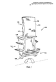
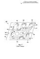
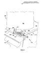
[103] В соответствии с фиг.1 и 2 рабочие лопатки 100 турбины в целом содержат аэродинамический элемент или аэродинамическую часть 102 и корневой элемент или корневую часть 104. Указанная аэродинамическая часть 102 может быть описана как имеющая выпуклую поверхность 105 со стороны пониженного давления и вогнутую поверхность 106 со стороны повышенного давления. Аэродинамическая часть 102 также может быть описана как имеющая ведущую кромку 107, которая является передней кромкой, и хвостовую кромку 108, которая является задней кромкой. Корневая часть 104 может быть описана как содержащая конструкцию (которая, как показано, обычно содержит элемент 109 пазового замка) для прикрепления лопатки 100 к валу ротора, платформу 110, от которой отходит аэродинамическая часть 102, и хвостовую часть 112, которая представляет собой конструкцию, расположенную между элементом 109 пазового замка и платформой 110.[103] In accordance with FIGS. 1 and 2,
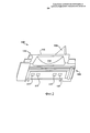
[104] Как показано, платформа 110 может быть по существу плоской. (Следует отметить, что под термином «плоский» в данном документе понимается приблизительно или по существу форма плоскости. Например, специалисту должно быть понятно, что платформы могут иметь наружную поверхность, которая выполнена слегка искривленной или выпуклой, причем указанная кривизна соответствует окружности турбины в местоположении рабочих лопаток в радиальном направлении. Применительно к данному документу платформа такого типа считается плоской, поскольку радиус кривизны достаточно велик для придания указанной платформе плоского внешнего вида). Более конкретно, платформа 110 может иметь плоскую верхнюю сторону 113, которая, как показано на фиг.1, может иметь проходящую в осевом и окружном направлениях плоскую поверхность. Как показано на фиг.2, платформа 110 может иметь плоскую нижнюю сторону 114, которая также может иметь проходящую в осевом и окружном направлениях плоскую поверхность. Верхняя сторона 113 и нижняя сторона 114 платформы 110 могут быть выполнены так, что каждая из них по существу параллельна другой. Как показано на чертеже и как должно быть понятно, платформа 110 обычно имеет тонкий радиальный профиль, т.е. расстояние между верхней стороной 113 и нижней стороной 114 платформы 110 в радиальном направлении относительно мало.[104] As shown, the
[105] Обычно платформа 110 используется в рабочих лопатках 100 турбины для формирования внутренней границы части проточного тракта для высокотемпературного газа в газовой турбине. Платформа 110 дополнительно обеспечивает конструкционную опору для аэродинамической части 102. При работе скорость вращения турбины обуславливает механическую нагрузку, которая создает области высокого механического напряжения вдоль платформы 110, которые в сочетании с высокими температурами в конечном счете приводят к возникновению эксплуатационных дефектов, таких как окисление, пластическая деформация, трещинообразование в условиях малоцикловой усталости и т.д. Разумеется, эти дефекты отрицательно влияют на эксплуатационный срок службы рабочей лопатки 100. Следует понимать, что такие жесткие условия эксплуатации, т.е. воздействие экстремальных температур, имеющих место в тракте прохождения высокотемпературных газов, и механической нагрузки, обусловленной вращающимися лопатками, создают значительные проблемы при проектировании надежных долговечных платформ 110 рабочих лопаток, которые обеспечивают качественное функционирование и при этом являются экономичными с точки зрения производства.[105] Typically,
[106] Одним общеизвестным решением, обеспечивающим более высокую надежность платформы 110, является ее охлаждение потоком сжатого воздуха или другой охлаждающей среды во время работы, при этом существует большое многообразие конструкций платформ такого типа. Однако, как должно быть понятно специалисту, область платформы 110 является проблематичной с конструктивной точки зрения, что затрудняет ее охлаждение указанным способом. В значительной степени это обусловлено сложной геометрической формой данной области, поскольку, как описано выше, платформа 110 является окружным элементом, проходящим от центральной части рабочей лопатки, и обычно выполнена достаточно прочной, но тонкой в радиальном направлении.[106] One well-known solution providing higher reliability of the
[107] Для обеспечения циркуляции охлаждающей среды рабочие лопатки 100 обычно имеют один или более полых охладительных каналов 116 (см. фиг.3, 4 и 5), которые по меньшей мере проходят в радиальном направлении через центральную часть лопатки 100, в том числе через корневую часть 104 и аэродинамическую часть 102. Как изложено более подробно ниже, для увеличения теплообмена такие охладительные каналы 116 могут быть выполнены в виде змеевидного тракта, который проходит через центральные области лопатки 100, хотя возможно использование других конфигураций. При работе охлаждающая среда может поступать в центральные охладительные каналы через одно или более впускных отверстий 117, выполненных во внутренней области корневой части 104. Охлаждающая среда может проходить через лопатку 100 и выходить через выпускные отверстия (не показаны), выполненные в аэродинамической части, и/или через одно или более выпускных отверстий (не показаны), выполненных в корневой части 104. Охлаждающая среда может быть сжатой средой и может содержать, например, сжатый воздух или сжатый воздух, смешанный с водой, паром и т.п. Во многих случаях охлаждающая среда является сжатым воздухом, отведенным из компрессора двигателя, хотя возможно использование и других источников. Как изложено более подробно ниже, указанные охладительные каналы обычно имеют область с охлаждающей средой под высоким давлением и область с охлаждающей средой под низким давлением. Указанная область с охлаждающей средой под высоким давлением обычно соответствует верхней по потоку части охладительного канала, в которой имеет место более высокое давление охлаждающей среды, тогда как область с охлаждающей средой под низким давлением соответствует нижней по потоку части, в которой имеет место относительно низкое давление охлаждающей среды.[107] To ensure the circulation of the cooling medium, the
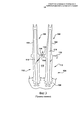
[108] В некоторых случаях охлаждающая среда может быть направлена из охладительных каналов 116 в полость 119, образованную между хвостовыми частями 112 и платформами 110 смежных лопаток 100. Здесь охлаждающая среда может использоваться для охлаждения платформы 110 указанной лопатки, типичная конструкция которой показана на фиг.3. Этот тип конструкции, как правило, обеспечивает извлечение воздуха из одного из охладительных каналов 116 и использование указанного воздуха для повышения давления в полости 119, образованной между хвостовыми частями 112/платформами 110. После повышения давления указанная полость 119 обеспечивает подачу охлаждающей среды к охладительным каналам, которые проходят через платформы 110. После пересечения платформы 110 охлаждающий воздух может выходить из указанной полости через отверстия пленочного охлаждения, выполненные на верхней стороне 113 платформы 110.[108] In some cases, the cooling medium may be directed from the
[109] Однако следует понимать, что этот тип общепринятой конструкции обладает несколькими недостатками. Во-первых, охладительный контур не заключен полностью в одном элементе, так как указанный контур образуется лишь после монтажа двух смежных лопаток 100. Это повышает степень сложности сборки и испытания проходимости потока при предварительной сборке. Второй недостаток заключается в том, что целостность полости 119, образованной между смежными лопатками 100, зависит от того, насколько качественно уплотнен периметр полости 119. Ненадлежащее уплотнение может привести к недостаточному охлаждению платформы и/или потере охлаждающего воздуха. Третий недостаток заключается в неизбежном риске попадания высокотемпературных газов из газового тракта в полость 119 или платформу 110. Это может произойти, если в полости 119 не поддерживается достаточно высокое давление во время эксплуатации. Если давление в полости 119 падает ниже значения давления в тракте прохождения горячих газов, то указанные газы проникают в полость 119 хвостовой части или в указанную платформу 110, что обычно наносит ущерб этим элементам, так как они не рассчитаны на воздействие высокотемпературных условий газового тракта.[109] However, it should be understood that this type of generally accepted design has several drawbacks. Firstly, the cooling circuit is not completely enclosed in one element, since the specified circuit is formed only after the installation of two
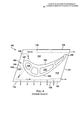
[110] Фиг.4 и 5 изображают другой тип общепринятой конструкции для охлаждения платформы. В данном случае, как показано, охладительный контур заключен внутри рабочей лопатки 100 и не захватывает полость 119 в хвостовой части. Охлаждающий воздух извлекают из одного из охладительных каналов 116, проходящих через центральную часть лопатки 110, и проводят в заднем направлении через охладительные каналы 120, выполненные внутри платформы 110 (т.е. «каналы 120 для охлаждения платформы»). Как показано несколькими стрелками, охлаждающий воздух проходит через каналы 120 и выходит через выпускные отверстия, расположенные в задней кромке 121 платформы 110, или из выпускных отверстий, расположенных вдоль кромки 122 со стороны пониженного давления. (Следует отметить, что при описании кромок или поверхностей прямоугольной платформы 110 или при ссылке на них границы каждой из них могут быть схематически установлены исходя из их местоположения относительно поверхности 105 со стороны пониженного давления и поверхности 106 со стороны повышенного давления аэродинамической части 102 и/или относительно переднего и заднего направлений двигателя после монтажа лопатки 100. По существу, как должно быть понятно специалисту, платформа может иметь заднюю кромку 121, кромку 122 со стороны пониженного давления, переднюю кромку 124 и кромку 126 со стороны повышенного давления, как показано на фиг.3 и 4. Кроме того, кромку 122 и кромку 126 обычно также называют «стыковочными поверхностями», а узкая полость, образующаяся между ними после установки соседних рабочих лопаток 100, может называться «полостью между стыковочными поверхностями»).[110] Figures 4 and 5 depict another type of conventional design for cooling a platform. In this case, as shown, the cooling circuit is enclosed within the
[111] Следует понимать, что общеизвестные конструкции, показанные на фиг.4 и 5, обладают преимуществом перед конструкцией, показанной на фиг.3, которое заключается в том, что на них не оказывают влияние изменения в условиях сборки или монтажа. Однако конструкции такого типа имеют несколько ограничений или недостатков. Во-первых, как показано, на каждой стороне аэродинамической части 102 выполнен лишь один контур, и соответственно возникает недостаток, заключающийся в ограниченном регулировании объема охлаждающего воздуха, используемого в различных местоположениях в платформе 110. Во-вторых, обычные конструкции такого типа имеют по существу ограниченную зону охвата. Несмотря на то, что змеевидный тракт, показанный на фиг.5, является улучшенным с точки зрения зоны охвата по сравнению с конструкцией, показанной на фиг.4, тем не менее, внутри платформы 110 имеются мертвые зоны, которые остаются неохлажденными. В-третьих, получение большей зоны охвата путем выполнения каналов 120 для охлаждения платформы, имеющих сложную форму, сильно повышает стоимость производства, в частности, если указанные охладительные каналы имеют форму, для выполнения которой необходимо использовать технологию литья. В-четвертых, в этих типичных конструкциях, как правило, охлаждающую среду сбрасывают в тракт высокотемпературных газов после ее использования, но до полной ее отработки, что отрицательно сказывается на эффективности двигателя. В-пятых, обычные конструкции такого типа имеют в целом недостаточную эксплуатационную гибкость. То есть каналы 120 выполнены в виде неотъемлемой части платформы 110, и поэтому в случае изменения рабочих условий они обеспечивают небольшую возможность для изменения их работы, или их формы, или вообще не обеспечивают такой возможности. Кроме того, общепринятые конструкции таких типов тяжело ремонтировать или реконструировать.[111] It should be understood that the well-known structures shown in FIGS. 4 and 5 have an advantage over the structure shown in FIG. 3, which is that they are not affected by changes in the conditions of assembly or installation. However, designs of this type have several limitations or disadvantages. Firstly, as shown, only one circuit is made on each side of the
[112] Таким образом, типичные конструкции для охлаждения платформы обладают недостатками в одной или более важных областях. Соответственно, существует необходимость в создании усовершенствованных устройств, систем и способов, которые обеспечивают эффективное охлаждение платформы рабочих лопаток, а также являются экономически эффективными с точки зрения изготовления, обладают эксплуатационной гибкостью и долговечностью.[112] Thus, typical constructions for cooling a platform have disadvantages in one or more important areas. Accordingly, there is a need to create improved devices, systems and methods that provide effective cooling of the platform of the working blades, and are also cost-effective from the point of view of manufacture, have operational flexibility and durability.
СУЩНОСТЬ ИЗОБРЕТЕНИЯSUMMARY OF THE INVENTION
[113] Таким образом, в данном изобретении предложено устройство охлаждения платформы, выполненное в турбинной рабочей лопатке, содержащей платформу, расположенную в области сопряжения аэродинамической части и корневой части, причем указанная рабочая лопатка имеет выполненный в ней внутренний охладительный канал, который проходит от соединения с источником охлаждающей среды в указанной корневой части приблизительно до уровня высоты указанной платформы в радиальном направлении, причем при эксплуатации указанный внутренний охладительный канал имеет область с охлаждающей средой под высоким давлением и область с охлаждающей средой под низким давлением, при этом вдоль стороны, которая совпадает со стороной пониженного давления аэродинамической части, сторона пониженного давления платформы имеет верхнюю сторону, проходящую в окружном направлении от аэродинамической части к стыковочной поверхности со стороны пониженного давления, при этом сторона пониженного давления платформы имеет заднюю кромку, которая совпадает с хвостовой кромкой аэродинамической части, и переднюю кромку, которая совпадает с ведущей кромкой аэродинамической части. Указанное устройство охлаждения платформы может содержать распределительный элемент, расположенный по меньшей мере в одной из передней и задней частей стороны пониженного давления платформы, соединитель высокого давления, соединяющий указанный распределительный элемент с указанной областью с охлаждающей средой под высоким давлением, имеющейся во внутреннем охладительном канале, соединитель низкого давления, соединяющий распределительный элемент с указанной областью с охлаждающей средой под низким давлением, имеющейся во внутреннем охладительном канале, и теплопередающую конструкцию, расположенную в распределительном элементе с обеспечением взаимодействия с охлаждающей средой, проходящей от соединителя высокого давления к соединителю низкого давления во время работы.[113] Thus, the present invention provides a platform cooling device made in a turbine working blade comprising a platform located in the interface between the aerodynamic part and the root part, said working blade having an internal cooling channel formed therein, which extends from the connection with a source of cooling medium in the specified root part to approximately the level of the height of the specified platform in the radial direction, and during operation, the specified internal cooling The first channel has a region with a high pressure cooling medium and a region with a low pressure cooling medium, while along the side that coincides with the lowered pressure side of the aerodynamic part, the lowered pressure side of the platform has an upper side extending in a circumferential direction from the aerodynamic part to the docking surface from the side of the reduced pressure, while the side of the reduced pressure of the platform has a trailing edge, which coincides with the tail edge of the aerodynamic part, and the front the edge, which coincides with the leading edge of the aerodynamic part. The specified platform cooling device may include a distribution element located at least in one of the front and rear parts of the low pressure side of the platform, a high pressure connector connecting the specified distribution element with the specified area with a high pressure cooling medium in the internal cooling channel, a connector low pressure connecting the distribution element with the specified area with a cooling medium under low pressure available in the inner a cooling channel, and a heat transfer structure located in the distribution element to ensure interaction with the cooling medium passing from the high pressure connector to the low pressure connector during operation.
[114] Эти и другие особенности данного изобретения станут более понятны из нижеследующего подробного описания предпочтительных вариантов выполнения при его рассмотрении совместно с чертежами и прилагаемой формулой изобретения.[114] These and other features of the present invention will become more apparent from the following detailed description of preferred embodiments when considered in conjunction with the drawings and the appended claims.
КРАТКОЕ ОПИСАНИЕ ЧЕРТЕЖЕЙBRIEF DESCRIPTION OF THE DRAWINGS
[115] Эти и другие особенности данного изобретения станут более очевидны и понятны при тщательном рассмотрении нижеследующего более подробного описания иллюстративных вариантов выполнения изобретения совместно с сопроводительными чертежами, на которых[115] These and other features of the present invention will become more apparent and understandable upon careful consideration of the following more detailed description of illustrative embodiments of the invention in conjunction with the accompanying drawings, in which
[116] фиг.1 изображает вид в аксонометрии иллюстративной рабочей турбинной лопатки, в которой могут использоваться варианты выполнения данного изобретения,[116] FIG. 1 is a perspective view of an illustrative working turbine blade in which embodiments of the invention may be used,
[117] фиг.2 изображает вид снизу рабочей турбинной лопатки, в которой могут использоваться варианты выполнения данного изобретения,[117] FIG. 2 is a bottom view of a working turbine blade in which embodiments of the invention may be used,
[118] фиг.3 изображает разрез смежных рабочих турбинных лопаток, содержащих охладительную систему в соответствии с общепринятой конструкцией,[118] figure 3 depicts a section of adjacent working turbine blades containing a cooling system in accordance with the generally accepted design,
[119] фиг.4 изображает вид сверху рабочей турбинной лопатки, содержащей платформу с внутренними охладительными каналами в соответствии с общепринятой конструкцией,[119] figure 4 depicts a top view of the working turbine blades containing a platform with internal cooling channels in accordance with the generally accepted design,
[120] фиг.5 изображает вид сверху рабочей турбинной лопатки, содержащей платформу с внутренними охладительными каналами в соответствии с другой общепринятой конструкцией,[120] figure 5 depicts a top view of the working turbine blades containing a platform with internal cooling channels in accordance with another conventional design,
[121] фиг.6 изображает вид в аксонометрии рабочей турбинной лопатки и устройства охлаждения платформы, выполненных в соответствии с иллюстративным вариантом выполнения данного изобретения,[121] Fig.6 depicts a perspective view of a working turbine blades and platform cooling devices, made in accordance with an illustrative embodiment of the present invention,
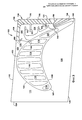
[122] фиг.7 изображает частичный вид сверху в разрезе рабочей турбинной лопатки и устройства охлаждения платформы, выполненных в соответствии с иллюстративным вариантом выполнения данного изобретения, и[122] Fig.7 depicts a partial top view in section of a working turbine blades and platform cooling devices made in accordance with an illustrative embodiment of the present invention, and
[123] фиг.8 изображает частичный вид сверху в разрезе рабочей турбинной лопатки и устройства охлаждения платформы, выполненных в соответствии с другим иллюстративным вариантом выполнения данного изобретения.[123] Fig. 8 depicts a partial top view in section of a working turbine blade and platform cooling device, made in accordance with another illustrative embodiment of the present invention.
[124] Следует понимать, что турбинные лопатки, охлаждение которых выполняется путем внутренней циркуляции охлаждающей среды, обычно имеют внутренний охладительный канал 116, который проходит в радиально наружном направлении от корневой части, через платформу в аэродинамическую часть, как описано выше в отношении нескольких типичных охладительных конструкций. Следует понимать, что конкретные варианты выполнения данного изобретения могут использоваться совместно с традиционными каналами для охлаждающей среды для улучшения или достижения эффективного активного охлаждения платформы, при этом данное изобретение описано применительно к типичной конструкции, т.е. внутренние охладительные каналы 116 имеют извилистую или змеевидную конфигурацию. Как показано на чертежах, змеевидный тракт обычно выполнен с обеспечением возможности однонаправленного прохождения охлаждающей среды и содержит элементы, способствующие теплообмену между охлаждающей средой и окружающей рабочей лопаткой 100. При эксплуатации сжатая охлаждающая среда, которая обычно является сжатым воздухом, выходящим из компрессора (хотя с вариантами выполнения данного изобретения также может использоваться охлаждающая среда других типов, например пар), подается к внутреннему каналу 116 через соединение, проходящее через корневую часть. Давление обеспечивает продвижение охлаждающей среды через канал 116, при этом указанная среда отводит тепло от окружающих стенок.[124] It should be understood that turbine blades, which are cooled by internal circulation of the cooling medium, typically have an
[125] Следует понимать, что при прохождении охлаждающей среды через канал 116 ее давление падает, при этом охлаждающая среда в верхних по потоку частях канала 116 имеет более высокое давление, чем охлаждающая среда в нижних по потоку частях. Как изложено более подробно ниже, данное падение давления может использоваться для продвижения охлаждающей среды через охладительные каналы, выполненные в платформе. Следует понимать, что данное изобретение может использоваться в рабочих лопатках 100, имеющих внутренние охладительные каналы с различными конфигурациями, и не ограничено внутренними охладительными каналами змеевидной формы. Соответственно, используемое в данном документе выражение «внутренний охладительный канал» или «охладительный канал» означает любой проход или полый канал, через который охлаждающая среда может циркулировать в рабочей лопатке. В данном случае внутренний канал 116 согласно изобретению проходит по меньшей мере приблизительно до уровня высоты платформы 116 в радиальном направлении и может иметь по меньшей мере одну область с относительно высоким давлением охлаждающей среды (которая далее называется «областью высокого давления» и в некоторых случаях может быть верхней по потоку частью в пределах змеевидного канала) и по меньшей мере одну область с относительно низким давлением охлаждающей среды (которая далее называется «областью низкого давления» и относительно области высокого давления может быть нижней по потоку частью в пределах змеевидного канала).[125] It should be understood that when the cooling medium passes through the
[126] В целом, различные конфигурации обычных внутренних охладительных каналов 116 являются эффективными при обеспечении активного охлаждения определенных областей внутри рабочей лопатки 100. Однако, как должно быть понятно специалисту, область платформы является весьма проблематичной. Это обусловлено, по меньшей мере частично, сложной геометрической формой платформы, т.е. ее малым размером в радиальном направлении и тем, как она выступает относительно центральной части или основного корпуса рабочей лопатки 100. Однако вследствие того, что платформа подвергается воздействию экстремальных температур, имеющих место в тракте для высокотемпературных газов, и воздействию механической нагрузки, значительно возрастают требования к охлаждению указанной платформы. Как изложено выше, обычные конструкции для охлаждения платформы являются неэффективными вследствие того, что они не в силах решить конкретные проблемы, связанные с указанной областью, а также неэффективными с точки зрения использования охлаждающей среды и/или дорогостоящими в изготовлении.[126] In general, various configurations of conventional
[127] На фиг.6-8 изображены несколько видов иллюстративных вариантов выполнения данного изобретения, т.е. устройства 130 для охлаждения платформы. Как показано на чертежах, в конкретных вариантах выполнения в задней части стороны 129 пониженного давления платформы 110 расположен распределительный элемент 134. Может быть выполнен соединитель 148 высокого давления, соединяющий распределительный элемент 134 с областью высокого давления внутреннего охладительного канала 116, и соединитель 149 низкого давления, соединяющий элемент 134 к областью низкого давления канала 116.[127] FIGS. 6-8 show several types of illustrative embodiments of the present invention, i.e.
[128] В распределительном элементе 134 может быть расположена теплопередающая конструкция, обеспечивающая взаимодействие с охлаждающей средой, проходящей от соединителя 148 высокого давления к соединителю 149 низкого давления во время работы. В конкретных вариантах выполнения, как показано на фиг.6 и 7, указанная теплопередающая конструкция может содержать набор стоек 162. В других вариантах выполнения теплопередающая конструкция может содержать извилистый тракт, как показано на фиг.8. Указанный извилистый тракт, проходящий через распределительный элемент 134, может быть образован чередующимися перегородками 163. Распределительный элемент 134 может содержать верхнее плоское перекрытие и нижнее плоское перекрытие, которые расположены по существу на постоянном расстоянии друг от друга в радиальном направлении и могут быть ориентированы так, что каждое из них может проходить по существу параллельно платформе 110. Стойки 162 могут представлять собой цилиндрические конструкции, проходящие между верхним и нижним перекрытиями элемента 134. Набор стоек 162 может содержать по меньшей мере пять стоек 162, разнесенных в пределах элемента 134. В других вариантах выполнения набор стоек 162 может содержать по меньшей мере десять стоек 162, разнесенных в пределах элемента 134. В других случаях теплопередающая конструкция может содержать набор параллельных охладительных каналов, проходящих в поперечном направлении через распределительный элемент 134 от соединителя 148 высокого давления к соединителю 149 низкого давления. Указанные параллельные каналы могут иметь стенки, проходящие между верхним и нижним перекрытиями элемента 134 аналогично прохождению перегородок 163, обеспечивающих направление охлаждающей среды через извилистый тракт.[128] A heat transfer structure may be disposed in the dispensing
[129] Платформа может иметь плоскую верхнюю сторону 113, которая приблизительно параллельна плоской нижней стороне 114. Распределительный элемент 134 может быть расположен между верхней стороной 113 и нижней стороной 114 приблизительно параллельно им. Теплопередающая конструкция и распределительный элемент 134 могут быть выполнены с обеспечением проведения охлаждающей среды через элемент 134 от соединителя 148 высокого давления к соединителю 149 низкого давления во время работы. Местоположение, в котором соединитель 148 присоединен к распределительному элементу 134, может находиться напротив местоположения, в котором соединитель 149 присоединен к указанному элементу 134, на расстоянии, соответствующем по меньшей мере значительной части элемента 134. Таким образом, охлаждающая среда, проходящая от соединителя 148 высокого давления к соединителю 149 низкого давления, может пересекать значительную часть распределительного элемента 134.[129] The platform may have a flat
[130] Распределительный элемент 134 может занимать положение в задней части стороны 129 пониженного давления платформы 110 (указанная сторона 129 находится с противоположной стороны аэродинамической части 102 от стороны 128 повышенного давления платформы 110) и иметь форму, которая приблизительно соответствует форме задней части указанной стороны 129 платформы 110. Соответственно, первая внутренняя стенка элемента 134 проходит с отнесением от контура стороны 105 пониженного давления основания аэродинамической части 102, вторая внутренняя стенка проходит приблизительно с отнесением от задней кромки 121 платформы 110, а третья внутренняя стенка проходит приблизительно с отнесением от стыковочной поверхности 122 со стороны пониженного давления платформы 110. Как показано на чертеже, распределительный элемент 134 может сужаться в осевом направлении по мере прохождения от первого местоположения около стыковочной поверхности 122 со стороны пониженного давления ко второму местоположению около стыковочной поверхности 126 со стороны повышенного давления. В некоторых вариантах выполнения элемент 134 может иметь приблизительно постоянную высоту в радиальном направлении по всей длине. В конкретных вариантах выполнения элемент 134 может быть выполнен так, что при эксплуатации по существу вся охлаждающая среда, проходящая через указанный элемент 134, может быть возвращена к внутреннему охладительному каналу через соединитель 149 низкого давления. В этом случае отверстия 156 могут отсутствовать, как показано на фиг.6, а формовочные выводы 165, образованные в процессе литья, могут быть полностью закрыты заглушками 164.[130] The dispensing
[131] В других вариантах выполнения между распределительным элементом 134 и стыковочной поверхностью 122 и задней кромкой 121 платформы могут проходить охладительные отверстия 156. Указанные отверстия 156 могут обеспечивать выход для части охлаждающей среды, проходящей через распределительный элемент 134. Охладительные отверстия 156 могут иметь заданное проходное сечение, которое соответствует требуемой характеристике ударного воздействия охлаждающей текучей среды. То есть отверстия 156 могут быть выполнены достаточно узкими для обеспечения направления выпускаемой охлаждающей среды со скоростью на стыковочную поверхность в смежной рабочей лопатке 100 и ее соударения с ней, что по существу повышает эффективность действия охлаждающий среды. Следует понимать, что полость между стыковочными поверхностями и стыковочные поверхности, ограничивающие указанную полость, представляют собой проблематичные для охлаждения области платформы 110, и что охладительные отверстия 156, выполненные в стыковочных поверхностях, могут эффективно решать эту проблему. Охладительные отверстия 156, выполненные вдоль задней кромки 121 платформы 110, аналогичным образом могут обеспечивать охлаждение данной области. В конкретных вариантах выполнения, как показано на фиг.8, могут иметься отверстия 166 пленочного охлаждения, соединяющие элемент 134 с проходами, выполненными в верхней стороне 113 платформы 110 и проходящими через указанную сторону. Охлаждающая среда, проходящая через эти отверстия, может обеспечивать пленочное охлаждение верхней стороны платформы 110. Охладительные отверстия 156 распределительного элемента 134 и отверстия 166 пленочного охлаждения могут быть выполнены таким образом или иметь такие размеры, что по меньшей мере 50% охлаждающей среды, проходящей через элемент 134, может быть возвращено к внутреннему охладительному каналу через соединитель 149 низкого давления.[131] In other embodiments, cooling holes 156 can extend between the
[132] Как показано на чертеже, соединитель 149 низкого давления может занимать положение около хвостовой кромки 108 аэродинамической части 102. Соединитель 148 высокого давления может занимать положение около средней области аэродинамической части 102. Более конкретно, соединитель 148 может проходить от местоположения внутри платформы 110, которое в профиль совмещено со средней областью аэродинамической части, к местоположению в платформе 110 около стыковочной поверхности 122 со стороны пониженного давления указанной платформы 110. Соединитель 149 может проходить от местоположения внутри платформы 110, которое в профиль совмещено с задней областью аэродинамической части 102, к местоположению в платформе 110 около задней кромки 121 платформы 110.[132] As shown, the
[133] При эксплуатации охладительное устройство в соответствии с данным изобретением может работать следующим образом. Часть подаваемой охлаждающей среды, проходящей через внутренний канал 116, поступает в соединитель 148 высокого давления. Затем охлаждающая среда проходит через распределительный элемент 134 и при прохождении через него отводит тепло от окружающей платформы 110 с обеспечением тем самым ее охлаждения. Таким образом, предложенное устройство 130 для охлаждения платформы извлекает часть охлаждающей среды из внутреннего охладительного канала 166, использует указанную охлаждающую среду для отведения тепла от платформы 110 и затем возвращает охлаждающую среду или по меньшей мере ее часть к каналу 116, из которого она может быть взята для дальнейшего использования.[133] In use, the cooling device in accordance with this invention can operate as follows. A portion of the supplied cooling medium passing through the
[134] Данное изобретение обеспечивает способ активного охлаждения области платформы рабочей лопатки турбины внутреннего сгорания. Как изложено выше, данная область обычно является проблематичной для охлаждения, и, учитывая действующие на нее механические нагрузки, представляет собой местоположение, которое подвержено сильным повреждениям при увеличении температур горения. Соответственно, данный тип активного охлаждения платформы представляет собой высокоэффективную технологию в случаях, когда необходимо достичь повышенных температур сгорания, повышенной мощности на выходе и более высокой эффективности.[134] The present invention provides a method for actively cooling an area of a platform of a working blade of an internal combustion turbine. As described above, this area is usually problematic for cooling, and, given the mechanical stresses acting on it, it represents a location that is susceptible to severe damage with increasing combustion temperatures. Accordingly, this type of active cooling of the platform is a highly efficient technology in cases where it is necessary to achieve increased combustion temperatures, increased output power and higher efficiency.
[135] Специалисту должно быть понятно, что различные особенности и конфигурации, описанные выше в отношении нескольких иллюстративных вариантов выполнения, могут дополнительно выборочно использоваться для создания других возможных вариантов выполнения данного изобретения. Для краткости и принимая во внимание квалификацию специалистов, в данном документе отсутствует подробное изложение и рассмотрение всех возможных этапов данного изобретения, но при этом все комбинации и возможные варианты выполнения, охватываемые несколькими пунктами нижеследующей формулы изобретения или иным образом, являются частью данного изобретения. Кроме того, на основании вышерассмотренных нескольких иллюстративных вариантов выполнения изобретения специалистами могут быть выполнены усовершенствования, изменения и модификации. Предполагается, что такие усовершенствования, изменения и модификации, очевидные для специалиста, также охватываются прилагаемой формулой изобретения. Более того, должно быть очевидным, что вышеизложенное относится только к описанным вариантам выполнения данного изобретения и что возможно выполнение многочисленных изменений и модификаций без отклонения от сущности и объема изобретения, определенных пунктами последующей формулы изобретения и их эквивалентами.[135] One skilled in the art will appreciate that the various features and configurations described above with respect to several illustrative embodiments can be further selectively used to create other possible embodiments of the present invention. For brevity and taking into account the qualifications of specialists, this document does not provide a detailed presentation and consideration of all possible steps of the present invention, but all the combinations and possible embodiments covered by several paragraphs of the following claims or otherwise are part of the present invention. In addition, based on the above several illustrative embodiments of the invention, specialists can make improvements, changes and modifications. It is assumed that such improvements, changes and modifications that are obvious to a person skilled in the art, are also covered by the attached claims. Moreover, it should be obvious that the foregoing applies only to the described embodiments of the present invention and that numerous changes and modifications are possible without deviating from the essence and scope of the invention defined by the paragraphs of the following claims and their equivalents.
Claims (20)
распределительный элемент, расположенный по меньшей мере в одной из передней и задней частей стороны пониженного давления платформы,
соединитель высокого давления, соединяющий распределительный элемент с указанной областью с охлаждающей средой под высоким давлением, имеющейся во внутреннем охладительном канале,
соединитель низкого давления, соединяющий распределительный элемент с указанной областью с охлаждающей средой под низким давлением, имеющейся во внутреннем охладительном канале, и
теплопередающую конструкцию, расположенную в распределительном элементе с обеспечением взаимодействия с охлаждающей средой, проходящей от соединителя высокого давления к соединителю низкого давления во время работы.1. A platform cooling device made in a turbine working blade containing a platform located in the interface between the aerodynamic part and the root part, said working blade having an internal cooling channel formed therein, which extends from being connected to a source of cooling medium in said root part to a height level of the specified platform in the radial direction and during operation has an area with a cooling medium under high pressure and an area with a cooling medium at the same time, along the side that coincides with the lowered pressure side of the aerodynamic part, the lowered pressure side of the platform has an upper side extending circumferentially from the aerodynamic part to the connecting surface from the lowered pressure side, while the lowered pressure side has a trailing edge , which coincides with the tail edge of the aerodynamic part, and the specified device cooling platform contains
a distribution element located at least in one of the front and rear parts of the low pressure side of the platform,
a high pressure connector connecting the distribution element to the specified area with a high pressure cooling medium present in the internal cooling channel,
a low pressure connector connecting the distribution element to the indicated area with a low pressure cooling medium present in the internal cooling channel, and
a heat transfer structure located in the distribution element to allow interaction with a cooling medium passing from the high pressure connector to the low pressure connector during operation.
компрессор,
топку,
турбину и
рабочую лопатку, содержащую устройство охлаждения платформы,
причем указанная рабочая лопатка содержит платформу, расположенную в области сопряжения аэродинамической части и корневой части, и имеет выполненный в ней внутренний охладительный канал, который проходит от соединения с источником охлаждающей среды в указанной корневой части приблизительно до уровня высоты указанной платформы в радиальном направлении и при эксплуатации имеет область с охлаждающей средой под высоким давлением и область с охлаждающей средой под низким давлением, при этом вдоль стороны, которая совпадает со стороной пониженного давления аэродинамической части, сторона пониженного давления платформы имеет верхнюю сторону, проходящую в окружном направлении от аэродинамической части к стыковочной поверхности со стороны пониженного давления, при этом сторона пониженного давления платформы имеет заднюю кромку, которая совпадает с хвостовой кромкой аэродинамической части, причем указанное устройство охлаждения платформы содержит
распределительный элемент, расположенный в задней части стороны пониженного давления платформы,
соединитель высокого давления, соединяющий указанный распределительный элемент с указанной областью с охлаждающей средой под высоким давлением, имеющейся во внутреннем охладительном канале,
соединитель низкого давления, соединяющий распределительный элемент с указанной областью с охлаждающей средой под низким давлением, имеющейся во внутреннем охладительном канале, и
теплопередающую конструкцию, расположенную в распределительном элементе с обеспечением взаимодействия с охлаждающей средой, проходящей от соединителя высокого давления к соединителю низкого давления во время работы. 20. A turbine internal combustion engine comprising
compressor,
firebox
turbine and
a working blade containing a platform cooling device,
moreover, said working blade contains a platform located in the interface between the aerodynamic part and the root part, and has an internal cooling channel made in it, which extends from the connection with the cooling medium source in the specified root part to approximately the height level of the specified platform in the radial direction and during operation has a region with a cooling medium under high pressure and a region with a cooling medium under low pressure, while along a side that coincides with the side on the lower pressure of the aerodynamic part, the low pressure side of the platform has an upper side extending in a circumferential direction from the aerodynamic part to the connecting surface from the low pressure side, while the low pressure side of the platform has a trailing edge that coincides with the tail edge of the aerodynamic part, said cooling device platform contains
a distribution element located at the rear of the low pressure side of the platform,
a high pressure connector connecting said distribution element with said region to a high pressure cooling medium present in the internal cooling channel,
a low pressure connector connecting the distribution element to the indicated area with a low pressure cooling medium present in the internal cooling channel, and
a heat transfer structure located in the distribution element to allow interaction with a cooling medium passing from the high pressure connector to the low pressure connector during operation.
Applications Claiming Priority (2)
| Application Number | Priority Date | Filing Date | Title |
|---|---|---|---|
| US13/341,027 US8905714B2 (en) | 2011-12-30 | 2011-12-30 | Turbine rotor blade platform cooling |
| US13/341,027 | 2011-12-30 |
Publications (2)
| Publication Number | Publication Date |
|---|---|
| RU2012158356A RU2012158356A (en) | 2014-07-10 |
| RU2605866C2 true RU2605866C2 (en) | 2016-12-27 |
Family
ID=47559124
Family Applications (1)
| Application Number | Title | Priority Date | Filing Date |
|---|---|---|---|
| RU2012158356/06A RU2605866C2 (en) | 2011-12-30 | 2012-12-27 | Platform cooling device and internal combustion turbine engine |
Country Status (5)
| Country | Link |
|---|---|
| US (1) | US8905714B2 (en) |
| EP (1) | EP2610436B1 (en) |
| JP (1) | JP2013139772A (en) |
| CN (1) | CN103184895B (en) |
| RU (1) | RU2605866C2 (en) |
Families Citing this family (22)
| Publication number | Priority date | Publication date | Assignee | Title |
|---|---|---|---|---|
| US8814518B2 (en) * | 2010-10-29 | 2014-08-26 | General Electric Company | Apparatus and methods for cooling platform regions of turbine rotor blades |
| US10001013B2 (en) * | 2014-03-06 | 2018-06-19 | General Electric Company | Turbine rotor blades with platform cooling arrangements |
| JP5606648B1 (en) | 2014-06-27 | 2014-10-15 | 三菱日立パワーシステムズ株式会社 | Rotor blade and gas turbine provided with the same |
| US9982542B2 (en) * | 2014-07-21 | 2018-05-29 | United Technologies Corporation | Airfoil platform impingement cooling holes |
| CN106715834B (en) | 2014-09-18 | 2019-01-08 | 西门子公司 | Aerofoil profile in gas-turbine unit and the cored structure for being used to form this aerofoil profile |
| CN107407151B (en) * | 2015-03-26 | 2019-08-06 | 三菱日立电力系统株式会社 | Blade and the gas turbine for having the blade |
| US9822653B2 (en) | 2015-07-16 | 2017-11-21 | General Electric Company | Cooling structure for stationary blade |
| US9988916B2 (en) * | 2015-07-16 | 2018-06-05 | General Electric Company | Cooling structure for stationary blade |
| JP5905631B1 (en) | 2015-09-15 | 2016-04-20 | 三菱日立パワーシステムズ株式会社 | Rotor blade, gas turbine provided with the same, and method of manufacturing rotor blade |
| JP6613803B2 (en) * | 2015-10-22 | 2019-12-04 | 三菱日立パワーシステムズ株式会社 | Blade, gas turbine provided with the blade, and method of manufacturing the blade |
| EP3287596A1 (en) * | 2016-08-25 | 2018-02-28 | Siemens Aktiengesellschaft | A platform cooling device for a blade of a turbomachine and a turbomachine arrangement |
| US10443404B2 (en) * | 2017-03-24 | 2019-10-15 | DOOSAN Heavy Industries Construction Co., LTD | Film and impingement platform cooling for serpentine cooled turbine blades |
| US10508548B2 (en) * | 2017-04-07 | 2019-12-17 | General Electric Company | Turbine engine with a platform cooling circuit |
| US11236625B2 (en) | 2017-06-07 | 2022-02-01 | General Electric Company | Method of making a cooled airfoil assembly for a turbine engine |
| US11225873B2 (en) * | 2020-01-13 | 2022-01-18 | Rolls-Royce Corporation | Combustion turbine vane cooling system |
| US11492908B2 (en) | 2020-01-22 | 2022-11-08 | General Electric Company | Turbine rotor blade root with hollow mount with lattice support structure by additive manufacture |
| US11220916B2 (en) | 2020-01-22 | 2022-01-11 | General Electric Company | Turbine rotor blade with platform with non-linear cooling passages by additive manufacture |
| US11248471B2 (en) | 2020-01-22 | 2022-02-15 | General Electric Company | Turbine rotor blade with angel wing with coolant transfer passage between adjacent wheel space portions by additive manufacture |
| US11242760B2 (en) | 2020-01-22 | 2022-02-08 | General Electric Company | Turbine rotor blade with integral impingement sleeve by additive manufacture |
| US11136890B1 (en) * | 2020-03-25 | 2021-10-05 | General Electric Company | Cooling circuit for a turbomachine component |
| US11174788B1 (en) * | 2020-05-15 | 2021-11-16 | General Electric Company | Systems and methods for cooling an endwall in a rotary machine |
| US20240011398A1 (en) * | 2022-05-02 | 2024-01-11 | Siemens Energy Global GmbH & Co. KG | Turbine component having platform cooling circuit |
Citations (5)
| Publication number | Priority date | Publication date | Assignee | Title |
|---|---|---|---|---|
| EP1205634A2 (en) * | 2000-11-03 | 2002-05-15 | General Electric Company | Cooling of a gas turbine blade |
| EP1621727A1 (en) * | 2004-07-30 | 2006-02-01 | General Electric Company | Turbine rotor blade and gas turbine engine rotor assembly comprising such blades |
| RU2369747C1 (en) * | 2008-02-07 | 2009-10-10 | Открытое акционерное общество "Авиадвигатель" | High-temperature two-stage gas turbine |
| RU2382885C2 (en) * | 2008-05-20 | 2010-02-27 | Государственное образовательное учреждение высшего профессионального образования Рыбинская государственная авиационная технологическая академия имени П.А. Соловьева | Nozzle vane of gas turbine with cyclone-swirler cooling system |
| US7695247B1 (en) * | 2006-09-01 | 2010-04-13 | Florida Turbine Technologies, Inc. | Turbine blade platform with near-wall cooling |
Family Cites Families (24)
| Publication number | Priority date | Publication date | Assignee | Title |
|---|---|---|---|---|
| US4739621A (en) * | 1984-10-11 | 1988-04-26 | United Technologies Corporation | Cooling scheme for combustor vane interface |
| US5165852A (en) * | 1990-12-18 | 1992-11-24 | General Electric Company | Rotation enhanced rotor blade cooling using a double row of coolant passageways |
| US5813835A (en) * | 1991-08-19 | 1998-09-29 | The United States Of America As Represented By The Secretary Of The Air Force | Air-cooled turbine blade |
| JPH0552102A (en) * | 1991-08-23 | 1993-03-02 | Toshiba Corp | Gas turbine |
| KR100364183B1 (en) * | 1994-10-31 | 2003-02-19 | 웨스팅하우스 일렉트릭 코포레이션 | Gas turbine blade with a cooled platform |
| JP2971386B2 (en) * | 1996-01-08 | 1999-11-02 | 三菱重工業株式会社 | Gas turbine vane |
| JP3457831B2 (en) * | 1997-03-17 | 2003-10-20 | 三菱重工業株式会社 | Gas turbine blade cooling platform |
| JP3276305B2 (en) * | 1997-05-01 | 2002-04-22 | 三菱重工業株式会社 | Gas turbine cooling vanes |
| JPH11166401A (en) * | 1997-12-03 | 1999-06-22 | Toshiba Corp | Gas turbine cooled blade |
| JP3546135B2 (en) * | 1998-02-23 | 2004-07-21 | 三菱重工業株式会社 | Gas turbine blade platform |
| US6190130B1 (en) * | 1998-03-03 | 2001-02-20 | Mitsubishi Heavy Industries, Ltd. | Gas turbine moving blade platform |
| JP2000220404A (en) * | 1999-01-28 | 2000-08-08 | Toshiba Corp | Gas turbine cooling blade |
| EP1188902A1 (en) * | 2000-09-14 | 2002-03-20 | Siemens Aktiengesellschaft | Impingement cooled wall |
| JP2005146858A (en) * | 2003-11-11 | 2005-06-09 | Mitsubishi Heavy Ind Ltd | Gas turbine |
| US7147439B2 (en) * | 2004-09-15 | 2006-12-12 | General Electric Company | Apparatus and methods for cooling turbine bucket platforms |
| US7255536B2 (en) * | 2005-05-23 | 2007-08-14 | United Technologies Corporation | Turbine airfoil platform cooling circuit |
| US7371049B2 (en) * | 2005-08-31 | 2008-05-13 | United Technologies Corporation | Manufacturable and inspectable microcircuit cooling for blades |
| US7416391B2 (en) * | 2006-02-24 | 2008-08-26 | General Electric Company | Bucket platform cooling circuit and method |
| US8011881B1 (en) * | 2008-01-21 | 2011-09-06 | Florida Turbine Technologies, Inc. | Turbine vane with serpentine cooling |
| US8096772B2 (en) * | 2009-03-20 | 2012-01-17 | Siemens Energy, Inc. | Turbine vane for a gas turbine engine having serpentine cooling channels within the inner endwall |
| US8079814B1 (en) * | 2009-04-04 | 2011-12-20 | Florida Turbine Technologies, Inc. | Turbine blade with serpentine flow cooling |
| US8523527B2 (en) * | 2010-03-10 | 2013-09-03 | General Electric Company | Apparatus for cooling a platform of a turbine component |
| US8794921B2 (en) * | 2010-09-30 | 2014-08-05 | General Electric Company | Apparatus and methods for cooling platform regions of turbine rotor blades |
| US8714909B2 (en) * | 2010-12-22 | 2014-05-06 | United Technologies Corporation | Platform with cooling circuit |
-
2011
- 2011-12-30 US US13/341,027 patent/US8905714B2/en active Active
-
2012
- 2012-12-13 EP EP12197045.3A patent/EP2610436B1/en active Active
- 2012-12-18 JP JP2012275237A patent/JP2013139772A/en active Pending
- 2012-12-27 RU RU2012158356/06A patent/RU2605866C2/en not_active IP Right Cessation
- 2012-12-28 CN CN201210586020.2A patent/CN103184895B/en active Active
Patent Citations (5)
| Publication number | Priority date | Publication date | Assignee | Title |
|---|---|---|---|---|
| EP1205634A2 (en) * | 2000-11-03 | 2002-05-15 | General Electric Company | Cooling of a gas turbine blade |
| EP1621727A1 (en) * | 2004-07-30 | 2006-02-01 | General Electric Company | Turbine rotor blade and gas turbine engine rotor assembly comprising such blades |
| US7695247B1 (en) * | 2006-09-01 | 2010-04-13 | Florida Turbine Technologies, Inc. | Turbine blade platform with near-wall cooling |
| RU2369747C1 (en) * | 2008-02-07 | 2009-10-10 | Открытое акционерное общество "Авиадвигатель" | High-temperature two-stage gas turbine |
| RU2382885C2 (en) * | 2008-05-20 | 2010-02-27 | Государственное образовательное учреждение высшего профессионального образования Рыбинская государственная авиационная технологическая академия имени П.А. Соловьева | Nozzle vane of gas turbine with cyclone-swirler cooling system |
Also Published As
| Publication number | Publication date |
|---|---|
| EP2610436A3 (en) | 2017-06-21 |
| CN103184895B (en) | 2016-03-16 |
| EP2610436B1 (en) | 2020-02-26 |
| CN103184895A (en) | 2013-07-03 |
| EP2610436A2 (en) | 2013-07-03 |
| US20130171005A1 (en) | 2013-07-04 |
| JP2013139772A (en) | 2013-07-18 |
| RU2012158356A (en) | 2014-07-10 |
| US8905714B2 (en) | 2014-12-09 |
Similar Documents
| Publication | Publication Date | Title |
|---|---|---|
| RU2605866C2 (en) | Platform cooling device and internal combustion turbine engine | |
| RU2605165C2 (en) | Turbine blade platform cooling device and method of said cooling device making | |
| US8684664B2 (en) | Apparatus and methods for cooling platform regions of turbine rotor blades | |
| US8814518B2 (en) | Apparatus and methods for cooling platform regions of turbine rotor blades | |
| US8734111B2 (en) | Platform cooling passages and methods for creating platform cooling passages in turbine rotor blades | |
| RU2605791C2 (en) | Platform cooling device intended for turbine rotary blade and its manufacturing method | |
| US8794921B2 (en) | Apparatus and methods for cooling platform regions of turbine rotor blades | |
| US8777568B2 (en) | Apparatus and methods for cooling platform regions of turbine rotor blades | |
| JP5898898B2 (en) | Apparatus and method for cooling the platform area of a turbine rotor blade | |
| US8840369B2 (en) | Apparatus and methods for cooling platform regions of turbine rotor blades | |
| US20120107135A1 (en) | Apparatus, systems and methods for cooling the platform region of turbine rotor blades | |
| JP6010295B2 (en) | Apparatus and method for cooling the platform area of a turbine rotor blade | |
| US20120171046A1 (en) | Apparatus and methods for cooling platform regions of turbine rotor blades | |
| EP3043031B1 (en) | Vane assembly, vane set, and method of manufacturing a vane assembly |
Legal Events
| Date | Code | Title | Description |
|---|---|---|---|
| MM4A | The patent is invalid due to non-payment of fees |
Effective date: 20201228 |