RU2596447C2 - Protective element and method of making protective element - Google Patents
Protective element and method of making protective element Download PDFInfo
- Publication number
- RU2596447C2 RU2596447C2 RU2013125471/12A RU2013125471A RU2596447C2 RU 2596447 C2 RU2596447 C2 RU 2596447C2 RU 2013125471/12 A RU2013125471/12 A RU 2013125471/12A RU 2013125471 A RU2013125471 A RU 2013125471A RU 2596447 C2 RU2596447 C2 RU 2596447C2
- Authority
- RU
- Russia
- Prior art keywords
- zones
- layer
- protective element
- region
- pattern
- Prior art date
Links
Images
Classifications
-
- B—PERFORMING OPERATIONS; TRANSPORTING
- B42—BOOKBINDING; ALBUMS; FILES; SPECIAL PRINTED MATTER
- B42D—BOOKS; BOOK COVERS; LOOSE LEAVES; PRINTED MATTER CHARACTERISED BY IDENTIFICATION OR SECURITY FEATURES; PRINTED MATTER OF SPECIAL FORMAT OR STYLE NOT OTHERWISE PROVIDED FOR; DEVICES FOR USE THEREWITH AND NOT OTHERWISE PROVIDED FOR; MOVABLE-STRIP WRITING OR READING APPARATUS
- B42D15/00—Printed matter of special format or style not otherwise provided for
-
- B—PERFORMING OPERATIONS; TRANSPORTING
- B42—BOOKBINDING; ALBUMS; FILES; SPECIAL PRINTED MATTER
- B42D—BOOKS; BOOK COVERS; LOOSE LEAVES; PRINTED MATTER CHARACTERISED BY IDENTIFICATION OR SECURITY FEATURES; PRINTED MATTER OF SPECIAL FORMAT OR STYLE NOT OTHERWISE PROVIDED FOR; DEVICES FOR USE THEREWITH AND NOT OTHERWISE PROVIDED FOR; MOVABLE-STRIP WRITING OR READING APPARATUS
- B42D25/00—Information-bearing cards or sheet-like structures characterised by identification or security features; Manufacture thereof
- B42D25/20—Information-bearing cards or sheet-like structures characterised by identification or security features; Manufacture thereof characterised by a particular use or purpose
- B42D25/29—Securities; Bank notes
-
- B—PERFORMING OPERATIONS; TRANSPORTING
- B42—BOOKBINDING; ALBUMS; FILES; SPECIAL PRINTED MATTER
- B42D—BOOKS; BOOK COVERS; LOOSE LEAVES; PRINTED MATTER CHARACTERISED BY IDENTIFICATION OR SECURITY FEATURES; PRINTED MATTER OF SPECIAL FORMAT OR STYLE NOT OTHERWISE PROVIDED FOR; DEVICES FOR USE THEREWITH AND NOT OTHERWISE PROVIDED FOR; MOVABLE-STRIP WRITING OR READING APPARATUS
- B42D25/00—Information-bearing cards or sheet-like structures characterised by identification or security features; Manufacture thereof
- B42D25/30—Identification or security features, e.g. for preventing forgery
- B42D25/324—Reliefs
-
- B—PERFORMING OPERATIONS; TRANSPORTING
- B42—BOOKBINDING; ALBUMS; FILES; SPECIAL PRINTED MATTER
- B42D—BOOKS; BOOK COVERS; LOOSE LEAVES; PRINTED MATTER CHARACTERISED BY IDENTIFICATION OR SECURITY FEATURES; PRINTED MATTER OF SPECIAL FORMAT OR STYLE NOT OTHERWISE PROVIDED FOR; DEVICES FOR USE THEREWITH AND NOT OTHERWISE PROVIDED FOR; MOVABLE-STRIP WRITING OR READING APPARATUS
- B42D25/00—Information-bearing cards or sheet-like structures characterised by identification or security features; Manufacture thereof
- B42D25/30—Identification or security features, e.g. for preventing forgery
- B42D25/328—Diffraction gratings; Holograms
-
- B—PERFORMING OPERATIONS; TRANSPORTING
- B42—BOOKBINDING; ALBUMS; FILES; SPECIAL PRINTED MATTER
- B42D—BOOKS; BOOK COVERS; LOOSE LEAVES; PRINTED MATTER CHARACTERISED BY IDENTIFICATION OR SECURITY FEATURES; PRINTED MATTER OF SPECIAL FORMAT OR STYLE NOT OTHERWISE PROVIDED FOR; DEVICES FOR USE THEREWITH AND NOT OTHERWISE PROVIDED FOR; MOVABLE-STRIP WRITING OR READING APPARATUS
- B42D25/00—Information-bearing cards or sheet-like structures characterised by identification or security features; Manufacture thereof
- B42D25/30—Identification or security features, e.g. for preventing forgery
- B42D25/342—Moiré effects
-
- B—PERFORMING OPERATIONS; TRANSPORTING
- B42—BOOKBINDING; ALBUMS; FILES; SPECIAL PRINTED MATTER
- B42D—BOOKS; BOOK COVERS; LOOSE LEAVES; PRINTED MATTER CHARACTERISED BY IDENTIFICATION OR SECURITY FEATURES; PRINTED MATTER OF SPECIAL FORMAT OR STYLE NOT OTHERWISE PROVIDED FOR; DEVICES FOR USE THEREWITH AND NOT OTHERWISE PROVIDED FOR; MOVABLE-STRIP WRITING OR READING APPARATUS
- B42D25/00—Information-bearing cards or sheet-like structures characterised by identification or security features; Manufacture thereof
- B42D25/30—Identification or security features, e.g. for preventing forgery
- B42D25/351—Translucent or partly translucent parts, e.g. windows
-
- B—PERFORMING OPERATIONS; TRANSPORTING
- B42—BOOKBINDING; ALBUMS; FILES; SPECIAL PRINTED MATTER
- B42D—BOOKS; BOOK COVERS; LOOSE LEAVES; PRINTED MATTER CHARACTERISED BY IDENTIFICATION OR SECURITY FEATURES; PRINTED MATTER OF SPECIAL FORMAT OR STYLE NOT OTHERWISE PROVIDED FOR; DEVICES FOR USE THEREWITH AND NOT OTHERWISE PROVIDED FOR; MOVABLE-STRIP WRITING OR READING APPARATUS
- B42D25/00—Information-bearing cards or sheet-like structures characterised by identification or security features; Manufacture thereof
- B42D25/30—Identification or security features, e.g. for preventing forgery
- B42D25/36—Identification or security features, e.g. for preventing forgery comprising special materials
- B42D25/364—Liquid crystals
-
- B—PERFORMING OPERATIONS; TRANSPORTING
- B42—BOOKBINDING; ALBUMS; FILES; SPECIAL PRINTED MATTER
- B42D—BOOKS; BOOK COVERS; LOOSE LEAVES; PRINTED MATTER CHARACTERISED BY IDENTIFICATION OR SECURITY FEATURES; PRINTED MATTER OF SPECIAL FORMAT OR STYLE NOT OTHERWISE PROVIDED FOR; DEVICES FOR USE THEREWITH AND NOT OTHERWISE PROVIDED FOR; MOVABLE-STRIP WRITING OR READING APPARATUS
- B42D25/00—Information-bearing cards or sheet-like structures characterised by identification or security features; Manufacture thereof
- B42D25/40—Manufacture
- B42D25/405—Marking
- B42D25/41—Marking using electromagnetic radiation
-
- B—PERFORMING OPERATIONS; TRANSPORTING
- B42—BOOKBINDING; ALBUMS; FILES; SPECIAL PRINTED MATTER
- B42D—BOOKS; BOOK COVERS; LOOSE LEAVES; PRINTED MATTER CHARACTERISED BY IDENTIFICATION OR SECURITY FEATURES; PRINTED MATTER OF SPECIAL FORMAT OR STYLE NOT OTHERWISE PROVIDED FOR; DEVICES FOR USE THEREWITH AND NOT OTHERWISE PROVIDED FOR; MOVABLE-STRIP WRITING OR READING APPARATUS
- B42D25/00—Information-bearing cards or sheet-like structures characterised by identification or security features; Manufacture thereof
- B42D25/40—Manufacture
- B42D25/405—Marking
- B42D25/43—Marking by removal of material
- B42D25/435—Marking by removal of material using electromagnetic radiation, e.g. laser
-
- B—PERFORMING OPERATIONS; TRANSPORTING
- B42—BOOKBINDING; ALBUMS; FILES; SPECIAL PRINTED MATTER
- B42D—BOOKS; BOOK COVERS; LOOSE LEAVES; PRINTED MATTER CHARACTERISED BY IDENTIFICATION OR SECURITY FEATURES; PRINTED MATTER OF SPECIAL FORMAT OR STYLE NOT OTHERWISE PROVIDED FOR; DEVICES FOR USE THEREWITH AND NOT OTHERWISE PROVIDED FOR; MOVABLE-STRIP WRITING OR READING APPARATUS
- B42D25/00—Information-bearing cards or sheet-like structures characterised by identification or security features; Manufacture thereof
- B42D25/40—Manufacture
- B42D25/405—Marking
- B42D25/43—Marking by removal of material
- B42D25/44—Marking by removal of material using mechanical means, e.g. engraving
-
- B—PERFORMING OPERATIONS; TRANSPORTING
- B42—BOOKBINDING; ALBUMS; FILES; SPECIAL PRINTED MATTER
- B42D—BOOKS; BOOK COVERS; LOOSE LEAVES; PRINTED MATTER CHARACTERISED BY IDENTIFICATION OR SECURITY FEATURES; PRINTED MATTER OF SPECIAL FORMAT OR STYLE NOT OTHERWISE PROVIDED FOR; DEVICES FOR USE THEREWITH AND NOT OTHERWISE PROVIDED FOR; MOVABLE-STRIP WRITING OR READING APPARATUS
- B42D25/00—Information-bearing cards or sheet-like structures characterised by identification or security features; Manufacture thereof
- B42D25/40—Manufacture
- B42D25/405—Marking
- B42D25/43—Marking by removal of material
- B42D25/445—Marking by removal of material using chemical means, e.g. etching
-
- B42D2033/04—
-
- B42D2035/14—
-
- B42D2035/16—
Abstract
Description
Изобретение относится к защитному элементу, в частности, к ценному документу, а также к способу изготовления защитного элемента.The invention relates to a security element, in particular, to a valuable document, as well as to a method of manufacturing a security element.
В области идентифицирующих (ID) документов известно использование прозрачных защитных элементов, которые в отражении имеют оптически переменное проявляющееся изображение, однако все еще обладают достаточной пропускной способностью, чтобы расположенную под этими защитными элементами информацию, например, индивидуализированные данные для персоны-обладателя ID-документа, делать или воспринимать еще видимой. Так, например, US 5411296 описывает подобный защитный элемент, который включает в себя пластиковую пленку, в которой отформован поверхностный рельеф голограммы. Эта пластиковая пленка заполнена по всей площади расположенными в регулярном растре точечными металлическими участками. Под этим защитным элементом располагается затем подложка ID-документа, например, паспорта, на котором находится, например, фото владельца паспорта, а также данные об этой персоне. Эта индивидуализированная информация, таким образом, наблюдается в качестве фона за голограммой, расположенной на переднем фоне.In the field of identification (ID) documents, it is known to use transparent security elements, which in reflection have an optically variable developing image, but still have sufficient bandwidth so that the information located under these security elements, for example, individualized data for the person who holds the ID document, make or perceive still visible. So, for example, US 5411296 describes a similar security element that includes a plastic film in which the surface relief of the hologram is molded. This plastic film is filled over the entire area with point metal sections located in a regular raster. Under this protective element is then the substrate of the ID document, for example, a passport, on which, for example, a photo of the passport holder is located, as well as information about this person. This individualized information is thus observed as a background behind a hologram located in the foreground.
В основе изобретения лежит задача, предложить улучшенный защитный элемент, а также улучшенный способ изготовления защитного элемента.The basis of the invention is the task of proposing an improved security element, as well as an improved method of manufacturing a security element.
Эта задача решается защитным элементом, который имеет область узора, состоящую из одного или нескольких элементов композиции, формообразование которой предоставляет первую оптически воспринимаемую информацию, и фоновую область, окружающую по меньшей мере на участках один или несколько элементов композиции области узора, причем защитный элемент имеет непрозрачный отражающий слой, который предусмотрен не в фоновой области, а предусмотрен в области узора в первых зонах, но не в одной или нескольких вторых зонах, или предусмотрен в одной или нескольких вторых зонах, но не в первых зонах, причем первые зоны разнесены менее чем на 300 мкм друг от друга и имеют наименьший размер менее 300 мкм. Эта задача также решается способом изготовления защитного элемента, в котором предоставляется прозрачная переводная пленка, которая имеет область, которая разделена на область узора, формообразование которой предоставляет первую информацию, и фоновую область, окружающую по меньшей мере на участках область узора, в котором в переводной пленке формуют непрозрачный отражающий слой, который предусмотрен не в фоновой области, а предусмотрен в области узора в первых зонах, но не в одной или нескольких вторых зонах, или предусмотрен в одной или нескольких вторых зонах, но не в первых зонах, причем первые зоны разнесены менее чем на 300 мкм друг от друга и имеют наименьший размер менее 300 мкм, и при котором переводная пленка наносится на подложку таким образом, что между переводной пленкой и подложкой располагается в особенности персонализированный декоративный слой, который предоставляет вторую информацию. Указанная задача также решается способом изготовления защитного элемента, в котором предоставляется защитный элемент, который имеет область узора, состоящую из одного или нескольких элементов композиции, формообразование которой предоставляет первую оптически воспринимаемую информацию, и фоновую область, окружающую по меньшей мере на участках один или несколько элементов композиции области узора, причем защитный элемент имеет непрозрачный отражающий слой, который предусмотрен не в фоновой области, а предусмотрен в области узора в первых зонах, но не в одной или нескольких вторых зонах, причем первые зоны разнесены менее чем на 300 мкм друг от друга и имеют наименьший размер менее 300 мкм, и при котором, в особенности, персонализированная или индивидуализированная информация записывается с помощью лазера в лазерно-чувствительный декоративный слой, расположенный под непрозрачным отражающим слоем, причем при записи непрозрачный отражательный слой расположен между лазером и декоративным слоем.This problem is solved by a protective element, which has a pattern area consisting of one or more composition elements, the formation of which provides the first optically perceptible information, and a background region surrounding at least in areas one or more composition elements of the pattern area, and the protective element has an opaque a reflective layer, which is not provided in the background area, but is provided in the pattern area in the first zones, but not in one or more second zones, or is provided in one and there are several second zones, but not in the first zones, and the first zones are spaced less than 300 microns apart and have the smallest size less than 300 microns. This problem is also solved by a method of manufacturing a protective element in which a transparent transfer film is provided, which has a region that is divided into a region of the pattern, the formation of which provides the first information, and a background region surrounding at least in parts the region of the pattern in which the transfer film forming an opaque reflective layer, which is not provided in the background area, but is provided in the pattern area in the first zones, but not in one or more second zones, or provided in one silt and several second zones, but not in the first zones, and the first zones are spaced less than 300 μm apart and have a smallest size of less than 300 μm, and in which the transfer film is applied to the substrate so that between the transfer film and the substrate is located Features a personalized decorative layer that provides second information. This problem is also solved by a method of manufacturing a security element in which a security element is provided that has a pattern area consisting of one or more elements of the composition, the formation of which provides the first optically perceptible information, and a background region surrounding at least one or more elements in the regions composition area of the pattern, and the protective element has an opaque reflective layer, which is not provided in the background area, but is provided in the pattern area in in the first zones, but not in one or more second zones, the first zones being spaced less than 300 microns apart and having the smallest size less than 300 microns, and in which, in particular, personalized or individualized information is recorded using a laser in a laser a sensitive decorative layer located under the opaque reflective layer, and when recording, an opaque reflective layer is located between the laser and the decorative layer.
Неожиданным образом оказалось, что посредством изобретения может быть улучшен блеск отражающего защитного признака, представленного в прозрачной области. Если, например, в случае соответствующего изобретению защитного элемента на первые зоны накладывается дополнительно структура рельефа, формирующая оптически переменный эффект, и под непрозрачным металлическим слоем предоставляется декоративный слой с второй информацией, то для человека-наблюдателя повышается блеск как первой, так и второй информации неожиданным образом по сравнению с решениями, известными из уровня техники.Surprisingly, it has been found that by means of the invention, the gloss of a reflective security feature presented in a transparent region can be improved. If, for example, in the case of a protective element according to the invention, an additional relief structure is formed on the first zones, forming an optically variable effect, and a decorative layer with second information is provided under the opaque metal layer, then for a human observer the brightness of both the first and second information increases unexpectedly way compared with solutions known from the prior art.
Обычно, в общем, принимается, что при расстоянии наблюдения, которое примерно соответствует нормальному расстоянию при чтении, то есть примерно 20-40 см, разрешающая способность невооруженного человеческого глаза лежит примерно при 300 мкм, то есть объекты, которые меньше, чем примерно 300 мкм, больше не разрешаются надежным образом, то есть больше не могут восприниматься как отдельные объекты.It is generally generally accepted that, with a viewing distance that approximately corresponds to the normal reading distance, that is, about 20-40 cm, the resolution of the naked human eye lies at about 300 microns, i.e. objects that are smaller than about 300 microns are no longer resolved in a reliable manner, that is, they can no longer be perceived as separate objects.
Так с помощью изобретения становится возможным, чувствительные области в персонализированном или индивидуализированном документе, как, например, фото или дату действительности или серийный номер, покрыть основанным на непрозрачном отражающем слое защитным признаком, при этом не ухудшая значительным образом распознаваемость этой области и этой информации. Персонализированная или индивидуализированная информация может, таким образом, безупречно распознаваться и при плохих условиях окружающего освещения, и защитный признак позволяет выполнять верификацию истинности и целостности документа.Thus, using the invention, it becomes possible to cover sensitive areas in a personalized or individualized document, such as a photo or a valid date or serial number, with a protective feature based on an opaque reflective layer, without significantly affecting the recognition of this area and this information. Personalized or individualized information can thus be perfectly recognized even under poor ambient lighting conditions, and a security feature allows verification of the truth and integrity of the document.
Выгодным является то, что за счет тонкого структурирования отражающего слоя с приводкой, то есть при точной приводке, то есть точном по положению размещении по отношению к элементам композиции, не происходит никакого ухудшения или конструктивного ограничения дифракционного признака, не считая снижения яркости. Кроме того, является предпочтительным согласовывать подструктурирование отражающего слоя на элементах композиции с величиной и формой элементов композиции, чтобы избежать проблем, которые проявились бы, например, при равномерном формировании растра отражающего слоя. Так исследования показали, что при равномерном формировании растра отражающего слоя, в частности, тонкие линии могли бы представляться лишь в недостаточной степени.Advantageously, due to the fine structure of the reflective layer with the register, that is, with accurate register, that is, positional placement with respect to the composition elements, there is no deterioration or structural restriction of the diffraction feature, apart from a decrease in brightness. In addition, it is preferable to coordinate the restructuring of the reflective layer on the composition elements with the size and shape of the composition elements in order to avoid problems that would occur, for example, if the reflection layer raster is uniformly formed. So studies have shown that with the uniform formation of a raster of the reflecting layer, in particular, thin lines could be represented only to an insufficient degree.
Если, как описано выше, информация, особенно персонализированная или индивидуализированная информация, записывается с помощью лазера в лазерно-чувствительный декоративный слой, расположенный ниже или выше непрозрачного отражающего слоя, то здесь предпочтительно применяется следующий способ. Лазер управляется таким образом, что области с непрозрачным отражающим слоем при записи информации нагружаются мощностью с пропусками или по меньшей мере с пониженной мощностью. Для этого, с одной стороны, может, например, с помощью соответствующего оптического датчика, определяться, имеет ли область, которая должна обрабатываться лазером, непрозрачный отражающий слой или не имеет его. Далее, также возможно эту информацию определять из сохраненного блока данных, который содержит структуру непрозрачного отражающего слоя. На участках, где должна записываться информация, но где предусмотрена область с непрозрачным отражающим слоем, либо снижается мощность лазера, либо запись информации в этой области посредством лазера не выполняется.If, as described above, information, especially personalized or individualized information, is recorded by laser into a laser-sensitive decorative layer located below or above the opaque reflective layer, then the following method is preferably applied. The laser is controlled in such a way that regions with an opaque reflecting layer are loaded with power with gaps or at least with reduced power when recording information. For this, on the one hand, it can, for example, be determined using an appropriate optical sensor whether the region to be processed by the laser has an opaque reflective layer or does not have it. Further, it is also possible to determine this information from a stored data block that contains the structure of an opaque reflective layer. In areas where information should be recorded, but where an area with an opaque reflective layer is provided, either the laser power is reduced, or information is not recorded in this area using a laser.
Согласно предпочтительному примеру выполнения изобретения защитный элемент имеет реплицирующий слой, в котором в первых зонах сформирован по меньшей мере на участках оптически активный поверхностный рельеф, в частности, для генерирования оптически переменных эффектов. Этот поверхностный рельеф предпочтительно имеет одну или несколько структур рельефа, выбранных из группы, включающей в себя дифракционную решетку, голограмму, отражательную рельефно-фазовую дифракционную решетку, линейную решетку, кроссрешетку, гексагональную решетку, асимметричную или симметричную решетчатую структуру, ретроотражательную структуру, преломляющую или дифракционную микролинзу, преломляющую или дифракционную микропризму, дифракционную структуру нулевого порядка, структуру типа глаза мотылька, или анизотропную или изотропную матовую структуру.According to a preferred embodiment of the invention, the security element has a replication layer in which in the first zones an optically active surface relief is formed at least in regions, in particular for generating optically variable effects. This surface relief preferably has one or more relief structures selected from the group consisting of a diffraction grating, a hologram, a reflective phase-diffraction grating, a linear grating, a cross grating, a hexagonal grating, an asymmetric or symmetric grating, a retroreflective structure, a refractive or diffractive a microlens, a refractive or diffractive microprism, a zero-order diffraction structure, a moth-eye structure, or anisotropic, or lyotropic matt structure.
Кроме того, является предпочтительным варьировать параметры рельефной структуры локально, например, ориентацию канавок решетки, форму профиля или глубину структуры или нескольких из этих параметров в комбинации.In addition, it is preferable to vary the parameters of the relief structure locally, for example, the orientation of the grooves of the lattice, the shape of the profile or the depth of the structure or several of these parameters in combination.
Решетчатые структуры могут к тому же быть изогнутыми или иметь стохастическую вариацию по меньшей мере одного параметра решетки, например, интервала, глубины структуры или формы профиля.The lattice structures can also be curved or have stochastic variation of at least one lattice parameter, for example, the interval, the depth of the structure or the shape of the profile.
Кроме того, поверхностный рельеф может состоять из равномерных, частично равномерных или случайных компоновок выступов и углублений. К тому же поверхностный рельеф может иметь ступенчато выполненную форму профиля, причем эти ступеньки имеют единую высоту. Кроме того, поверхностный рельеф может включать в себя аддитивную или субтрактивную суперпозицию двух или более вышеназванных структур рельефа. Под дифракционной решеткой понимается структура рельефа с пространственной частотой от 100 до 5000 линий/мм, структурные элементы которой предпочтительно имеют глубину структуры от 0,1 до 20 мкм, особенно от 0,1 до 10 мкм. В качестве отражательной рельефно-фазовой дифракционной решетки предпочтительно используются структуры рельефа с треугольными структурными элементами, которые расположены на расстоянии от 0,2 до 10 мкм друг от друга. В качестве микролинз предпочтительно используются цилиндрические линзы или сферические линзы с фокусным расстоянием от 5 до 500 мкм и/или глубиной структуры от 0,1 до 50 мкм.In addition, the surface relief may consist of uniform, partially uniform or random layouts of protrusions and recesses. In addition, the surface relief may have a stepwise shaped profile shape, and these steps have a single height. In addition, the surface relief may include an additive or subtractive superposition of two or more of the above relief structures. By a diffraction grating is meant a relief structure with a spatial frequency of 100 to 5000 lines / mm, the structural elements of which preferably have a structural depth of 0.1 to 20 μm, especially 0.1 to 10 μm. As a reflective phase-relief diffraction grating, relief structures with triangular structural elements that are located at a distance of 0.2 to 10 μm from each other are preferably used. As microlenses, cylindrical lenses or spherical lenses with a focal length of 5 to 500 μm and / or a structure depth of 0.1 to 50 μm are preferably used.
В качестве микропризм предпочтительно используются микропризмы, которые имеют глубину структуры от 0,1 до 25 мкм, ширину структуры у основания от 5 до 300 мкм, и находятся на расстоянии предпочтительно от 5 до 300 мкм друг от друга.As microprisms, microprisms are preferably used that have a structure depth of 0.1 to 25 μm, a structure width at the base of 5 to 300 μm, and are preferably at a distance of 5 to 300 μm from each other.
В качестве матовых структур предпочтительно применяются матовые структуры с интервалом корреляции от 0,2 до 20 мкм. В качестве дифракционных структур нулевого порядка предпочтительно используются регулярные структуры с пространственной частотой более 2000 линий/мм.As the matte structures, matte structures with a correlation interval of 0.2 to 20 microns are preferably used. Regular structures with a spatial frequency of more than 2000 lines / mm are preferably used as zero order diffraction structures.
При этом поверхностный рельеф предпочтительно имеет различные области, которые покрыты различными вышеописанными структурами рельефа. Под различными структурами рельефа понимаются, с одной стороны, структуры рельефа, которые при формообразовании структурных элементов и/или в их расположении относительно друг друга различаются в одном или нескольких параметрах структуры, например, имеют отличающуюся пространственную частоту и/или отличающийся азимутальный угол. Области могут иметь граничные линии относительно смежных областей, на которых вышеназванные свойства структур рельефа скачкообразно изменяются. Кроме того, возможны и непрерывные локальные переходы параметров структур рельефа. Кроме того, также возможны квазинепрерывные локальные переходы параметров структур рельефа, например, локальное чередование, то есть вложенное друг в друга или попеременное расположение частичных областей соответствующих пограничных структур рельефа в области перехода.In this case, the surface relief preferably has different regions that are covered by the various relief structures described above. Various relief structures are understood, on the one hand, as relief structures, which, when forming structural elements and / or in their arrangement relative to each other, differ in one or more structural parameters, for example, have a different spatial frequency and / or a different azimuthal angle. Regions can have boundary lines relative to adjacent regions, on which the above-mentioned properties of relief structures change stepwise. In addition, continuous local transitions of the parameters of the relief structures are also possible. In addition, quasicontinuous local transitions of the parameters of the relief structures, for example, local alternation, that is, nested into each other or alternating arrangement of partial regions of the corresponding boundary relief structures in the transition region, are also possible.
Особое преимущество имеет место, когда поверхностный рельеф предусмотрен с приводкой, то есть точно по положению, относительно первых зон. Так особенно предпочтительно, если во вторых зонах и/или в фоновой области не сформирован никакой поверхностный рельеф в реплицирующем слое лака, или там сформирован поверхностный рельеф, который отличается от сформированного в первых зонах поверхностного рельефа. Так, например, поверхностный рельеф во вторых зонах и/или в фоновой области определяется только обусловленной изготовлением шероховатостью поверхности реплицирующего слоя лака и имеет, таким образом, например, глубину структуры или глубину шероховатости (высоту неровностей рельефа) менее 100 нм или имеет там структуру рельефа, отличающуюся от структуры рельефа в первых зонах, в частности, структуру рельефа, характеристическое отношение которой отличается от сформированного в первых зонах поверхностного рельефа на по меньшей мере 25%, в особенности на по меньшей мере 50%. Под характеристическим отношением здесь понимается отношение глубины рельефа к ширине структурных элементов структуры рельефа. Оказалось, что за счет подобного выполнения поверхностного рельефа, сформированного в реплицирующем слое лака, блеск, а также устойчивость по отношению к подделкам защитного элемента может заметно повышаться. Так, например, ориентация с точной приводкой, то есть точная по положению ориентация поверхностного рельефа по отношению к первым зонам, может быть реализована только посредством значительных технологических затрат, и попытки подделки или попытки манипулирования становятся непосредственно распознаваемыми, так как, например, при удалении или манипулировании одним из слоев, оптически переменная информация, ввиду возникающих отклонений в приводке, то есть отклонений от точности по положению ориентации поверхностного рельефа к первым зонам, непосредственно изменяется и, таким образом, искажения могут однозначным образом идентифицироваться.A particular advantage occurs when the surface relief is provided with a register, i.e. precisely in position, relative to the first zones. So it is especially preferred if no surface pattern is formed in the second zones and / or in the background region in the replicating varnish layer, or a surface pattern is formed there that is different from that formed in the first zones of the surface pattern. So, for example, the surface relief in the second zones and / or in the background region is determined only by the roughness of the surface of the replicating varnish layer due to the manufacture and, therefore, has, for example, the depth of structure or the depth of roughness (height of the roughness of the relief) less than 100 nm or has a relief structure there that differs from the relief structure in the first zones, in particular, the relief structure, whose characteristic ratio differs from the surface relief formed in the first zones by at least 25%, in particular at least 50% of cash. Here, the characteristic ratio is understood as the ratio of the depth of the relief to the width of the structural elements of the relief structure. It turned out that due to the similar implementation of the surface relief formed in the replicating layer of varnish, the gloss, as well as resistance to fakes of the protective element can significantly increase. So, for example, orientation with a precise register, that is, an exact position orientation of the surface relief with respect to the first zones, can be realized only by means of significant technological costs, and attempts to fake or attempt to manipulate become directly recognizable, since, for example, when removing or manipulating one of the layers, optically variable information, due to deviations in the register, i.e. deviations from accuracy in the orientation of the surface relief to the first am, varies directly and thus distortions may be uniquely identified.
Предпочтительным образом поверхностный рельеф сформирован в поверхности реплицирующего слоя, обращенной к непрозрачному отражающему слою и, в частности, на граничной плоскости между реплицирующим слоем и непрозрачным отражающим слоем.Preferably, a surface relief is formed on the surface of the replicating layer facing the opaque reflective layer and, in particular, on the boundary plane between the replicating layer and the opaque reflective layer.
Согласно предпочтительному примеру выполнения изобретения, во множестве первых зон сформирована, соответственно, микролинза или микропризма в качестве поверхностного рельефа. При этом формирование поверхности и размеры поверхности соответствующих, снабженных микролинзой или микропризмой первых зон, в частности, выбраны таким образом, что соответствующая микролинза или соответствующая микропризма занимает всю площадь соответствующей первой зоны. Структурирование непрозрачного отражающего слоя в области узора осуществляется тем самым с точной приводкой, то есть точно по положению отдельных линз, так что каждая линза полностью имеет отражающий слой, а фон полностью не имеет никакого отражающего слоя и является прозрачным или просвечивающим или пропускающим свет (полупрозрачным). Тем самым блеск защитных признаков защитного элемента, а также его устойчивость по отношению к подделкам дополнительно улучшается.According to a preferred embodiment of the invention, a microlens or microprism is formed in the plurality of first zones, respectively, as a surface relief. In this case, the surface formation and surface dimensions of the respective first zones equipped with a microlens or microprism are in particular selected so that the corresponding microlens or the corresponding microprism occupies the entire area of the corresponding first zone. The structure of the opaque reflective layer in the region of the pattern is thereby carried out with precise registering, i.e. precisely according to the position of the individual lenses, so that each lens has a fully reflective layer, and the background has no reflective layer and is transparent or translucent or transmissive (translucent) . Thus, the gloss of the security features of the security element, as well as its resistance to counterfeiting, is further improved.
Согласно другому предпочтительному примеру выполнения изобретения, доля площади соответствующих первых зон, которая занята поверхностным рельефом, в области узора локально варьируется. Тем самым является возможным варьировать яркость, с которой область узора представляется в различных направлениях наблюдения, и, тем самым, повышать оптическую сложность защитного признака, предоставляемого защитным элементом. При этом особенно предпочтительно поддерживать величину площади этой первой зоны постоянной. Тем самым достигается преимущество, заключающееся в том, что оптическое представляемое изображение второй оптической информации, возможно предусмотренной под непрозрачным оптически отражающим слоем, не подвергается влиянию, и, таким образом, эти изменения яркости представляются особенно выразительными.According to another preferred embodiment of the invention, the proportion of the area of the respective first zones, which is occupied by the surface relief, locally varies in the pattern area. Thus, it is possible to vary the brightness with which the region of the pattern appears in different directions of observation, and thereby increase the optical complexity of the security feature provided by the security element. Moreover, it is particularly preferable to maintain the area of this first zone constant. Thereby, the advantage is achieved that the optical image of the second optical information, possibly provided under an opaque optically reflective layer, is not affected, and thus, these changes in brightness seem particularly expressive.
Согласно другому предпочтительному примеру выполнения изобретения, первые зоны, предпочтительно каждая из первых зон элемента композиции или области узора подразделена на n частичных зон, в которых сформированы различные структуры рельефа в качестве поверхностного рельефа в реплицирующем слое, причем n≥2. Так, например, в первой частичной зоне в качестве структуры рельефа сформирована дифракционная решетка, во второй частичной зоне - матовая структура, и в третьей частичной зоне - зеркальная поверхность. Тем самым становится возможным в области узора предоставить оптический защитный признак, который мог бы быть имитирован лишь с большим трудом. Так, например, можно генерировать в области узора оптически переменные эффекты, которые не могут быть реализованы посредством голограммы и которые, таким образом, например, при расположении без приводки, то есть не при точном по положению расположении первых зон к структуре рельефа не могут быть реализованы.According to another preferred embodiment of the invention, the first zones, preferably each of the first zones of the composition element or the pattern area, are divided into n partial zones in which various relief structures are formed as a surface relief in the replicating layer, n≥2. For example, in the first partial zone, a diffraction grating is formed as a relief structure, in the second partial zone, an opaque structure, and in the third partial zone, a mirror surface. Thus, it becomes possible to provide an optical security feature in the area of the pattern, which could only be imitated with great difficulty. So, for example, it is possible to generate optically variable effects in the pattern area that cannot be realized by means of a hologram and which, therefore, for example, when arranged without register, that is, when the position of the first zones to the relief structure is exact in position, cannot be realized .
Кроме того, является предпочтительным, если соответственно одна из частичных зон каждой из этих первых зон ассоциирована с некоторым направлением наблюдения. Так, например, предусматривается m направлений наблюдения, и каждая из этих первых зон имеет n≥m частичных зон, которые, соответственно, ассоциированы с соответствующим одним из m направлений наблюдения. Частичные зоны первых зон, ассоциированные с направлением наблюдения, предпочтительно покрыты одной и той же структурой рельефа. Кроме того, является предпочтительным, если величина площади каждой частичной зоны локально варьируется для определения локальной яркости в направлении наблюдения, ассоциированном с соответствующими частичным зонами. Дополнительно или альтернативно этому, также возможно, что частичные зоны первых зон ассоциированы с соответствующим одним из k цветовых компонентов. Так, например, возможно, что предусмотрены три цветовых компонента (R, G, B, что означает, например, красный, зеленый, синий), и первая зона имеет соответственно три частичных зоны, из которых соответственно первая ассоциирована с цветовой компонентой R, вторая - с цветовой компонентой G, и третья - с цветовой компонентой В. И в данном случае является предпочтительным, если частичные зоны, ассоциированные с одной и той же цветовой компонентой, имеют ту же самую структуру рельефа. Кроме того, и здесь возможно, что величина площади соответствующих частичных зон варьируется локально для определения локальной яркости и значения света. Тем самым обеспечивается возможность того, что в прозрачной области генерируются видимые в отражении изображения натурального цвета и/или в варьирующиеся в различных направлениях по своей яркости и/или значению цвета изображения в качестве защитного признака. Уже при k=2 могут представляться изображения, которые формируют впечатление натурального цвета. Цветовое пространство хотя и ограничено, но несмотря на это достаточно для многих приложений. Преимущество состоит, в частности, в том, что необходимы только 2 частичных зоны. С другой стороны, представляемое цветовое пространство может увеличиваться при k≥2, в особенности k≥3, в то время как, в качестве недостатка, может потребоваться больше частичных зон.In addition, it is preferable if, respectively, one of the partial zones of each of these first zones is associated with a certain direction of observation. So, for example, m observation directions are provided, and each of these first zones has n≥m partial zones, which, respectively, are associated with the corresponding one of the m observation directions. Partial zones of the first zones associated with the direction of observation are preferably covered by the same relief structure. In addition, it is preferable if the size of the area of each partial zone varies locally to determine the local brightness in the direction of observation associated with the respective partial zones. Additionally or alternatively, it is also possible that the partial zones of the first zones are associated with the corresponding one of k color components. So, for example, it is possible that three color components are provided (R, G, B, which means, for example, red, green, blue), and the first zone has three partial zones, respectively, of which the first is associated with the color component R, the second - with the color component G, and the third with the color component B. And in this case, it is preferable if the partial zones associated with the same color component have the same relief structure. In addition, it is also possible here that the area size of the corresponding partial zones varies locally to determine the local brightness and value of light. This makes it possible that in the transparent region generated visible in reflection images of natural color and / or varying in different directions in terms of brightness and / or color value of the image as a protective feature. Already at k = 2, images can be presented that form the impression of a natural color. The color space, although limited, is nevertheless sufficient for many applications. The advantage, in particular, is that only 2 partial zones are needed. On the other hand, the color space presented may increase at k≥2, in particular k≥3, while, as a disadvantage, more partial zones may be required.
Кроме того, является предпочтительным, если первые зоны имеют частичную зону, в которых не сформирована никакая структура рельефа в реплицирующем слое. Так, например, возможно, что первая оптическая информация имеет локально различную яркость в отражении, которая определяется посредством соответствующей локальной величины площади первой зоны и перекрывается оптически переменной информацией, которая определяется типом и долей площади сформированных в соответствующих первых зонах структур рельефа. Кроме того, за счет этого также различные информации генерируются посредством защитного элемента при пропускании и отражении.In addition, it is preferable if the first zones have a partial zone in which no relief structure is formed in the replicating layer. So, for example, it is possible that the first optical information has a locally different brightness in reflection, which is determined by the corresponding local value of the area of the first zone and is overlapped by optically variable information, which is determined by the type and fraction of the area of the relief structures formed in the corresponding first zones. In addition, due to this, various information is also generated by the security element during transmission and reflection.
Согласно другому предпочтительному примеру выполнения изобретения, ширина, длина и/или промежуток первых зон варьируются в муаровой области для генерации скрытой муаровой информации, которая при суперпозиции с ассоциированным муаровым верификационным элементом наблюдается как третья информация в муаровой области.According to another preferred embodiment of the invention, the width, length and / or span of the first zones are varied in the moire region to generate hidden moire information, which when superposed with the associated moire verification element is observed as third information in the moire region.
Так муаровая область разделена, например, на муаровую фоновую область и муаровую область узора.So the moire region is divided, for example, into the moire background region and the moire region of the pattern.
Например, ширина, длина и/или интервал первых зон в муаровой фоновой области и муаровой области узора имеют слегка различающиеся значения параметров (которые выбраны в области ширины растра структурных элементов муарового верификационного элемента), так что при суперпозиции с муаровым верификационным элементом муаровая область узора становится видимой относительно муаровой фоновой области. В качестве верификационного элемента могут служить печатные, металлизированные или иным образом структурированные одномерные или двумерные растры, в частности, одномерные или двумерные микролинзовые растры или линейные растры. Разницы в значениях параметров (ширина, длина и/или интервал) для муаровой области узора и муаровой фоновой области и соответствующие значения параметров муарового верификационного элемента различаются типично в диапазоне от 0,1% до 10%.For example, the width, length and / or interval of the first zones in the moire background region and the moire region of the pattern have slightly different parameter values (which are selected in the raster width region of the structural elements of the moire verification element), so that when superposed with the moire verification element, the moire region of the pattern becomes visible relative to the moire background. As a verification element, printed, metallized or otherwise structured one-dimensional or two-dimensional rasters, in particular, one-dimensional or two-dimensional microlens rasters or linear rasters, can serve. Differences in the parameter values (width, length and / or interval) for the moire region of the pattern and the moire background region and the corresponding values of the parameters of the moire verification element differ typically in the range from 0.1% to 10%.
Согласно другому предпочтительному примеру выполнения изобретения, внутри оптически активного поверхностного рельефа первых зон для генерации скрытой муаровой информации предусмотрено подструктурирование оптически активного поверхностного рельефа, причем скрытая муаровая информация при суперпозиции с ассоциированным муаровым верификационным элементом является видимой в качестве третьей информации. Так, например, в качестве параметров выбираются форма рельефа и/или глубина структуры и/или азимутальный угол и/или пространственная частота оптически активного поверхностного рельефа в муаровой фоновой области и в муаровой области узора скрытой муаровой информации слегка различными, а также слегка различными по отношению к соответствующим параметрам муарового верификационного элемента, так что при суперпозиции с муаровым верификационным элементом муаровая область узора является видимой относительно муаровой фоновой области.According to another preferred embodiment of the invention, within the optically active surface relief of the first zones for generating hidden moire information, a substructuring of the optically active surface relief is provided, the hidden moire information being superposed with the associated moire verification element is visible as third information. So, for example, the shape of the relief and / or the depth of the structure and / or the azimuthal angle and / or spatial frequency of the optically active surface relief in the moire background region and in the moire region of the latent moire information pattern are slightly different and slightly different in relation to the parameters to the corresponding parameters of the moire verification element, so that when superposed with the moire verification element, the moire region of the pattern is visible relative to the moire background region.
В качестве муарового верификационного элемента могут служить печатные, металлизированные или иным образом структурированные одномерные или двумерные растры, в частности, одномерные или двумерные микролинзовые растры или линейные растры. Различия в значениях параметров (ширина, длина и/или интервал) для муаровой области узора и муаровой фоновой области и соответствующие значения параметров муарового верификационного элемента различаются типично в диапазоне от 0,1% до 10%. Например, муаровая область узора и/или муаровая фоновая область могут выполняться в форме одномерных сплющенных элементов композиции, которые посредством муарового верификационного элемента подвергаются муаровому увеличению и при перемещении муарового верификационного элемента проявляют динамические эффекты.As the moire verification element, printed, metallized, or otherwise structured one-dimensional or two-dimensional rasters can be used, in particular, one-dimensional or two-dimensional microlens rasters or linear rasters. Differences in the parameter values (width, length and / or interval) for the moire region of the pattern and the moire background region and the corresponding values of the parameters of the moire verification element differ typically in the range from 0.1% to 10%. For example, the moire region of the pattern and / or the moire background region can be in the form of one-dimensional flattened composition elements, which, through the moire verification element, undergo a moire increase and exhibit dynamic effects when the moire verification element is moved.
Особенно интересными являются при этом анимированные, в частности, одномерные или двумерные муаровые эффекты, которые становятся видимыми при наклоне защитного элемента и/или при относительном перемещении муарового верификационного элемента относительно области узора скрытой муаровой информации.Of particular interest are animated, in particular, one-dimensional or two-dimensional moire effects, which become visible when the security element is tilted and / or when the moire verification element moves relative to the pattern area of the hidden moire information.
Согласно другому предпочтительному примеру выполнения изобретения, первые зоны в области узора расположены согласно одномерному или двумерному растру, причем ширина растра составляет, в частности, между 5 и 1000 мкм, более предпочтительно между 20 и 500 мкм и еще более предпочтительно между 25 и 250 мкм. При этом растр может представлять собой периодический растр. Однако также возможно, что речь идет о нерегулярном или также стохастическом растре, который, в частности, согласован с формообразованием элементов композиции.According to another preferred embodiment of the invention, the first zones in the region of the pattern are arranged according to a one-dimensional or two-dimensional raster, the raster width being, in particular, between 5 and 1000 microns, more preferably between 20 and 500 microns and even more preferably between 25 and 250 microns. In this case, the raster may be a periodic raster. However, it is also possible that this is an irregular or also stochastic raster, which, in particular, is consistent with the shaping of composition elements.
Кроме того, особенно предпочтительно, если доля площади первых зон в области узора составляет от 1 до 80% в частности, от 2 до 50%.In addition, it is particularly preferable if the proportion of the area of the first zones in the region of the pattern is from 1 to 80%, in particular from 2 to 50%.
Далее предпочтительно, если промежутки между первыми зонами составляют от 25 до 250 мкм и/или что ширина и/или длина первых зон выбирается в диапазоне от 5 до 100 мкм.It is further preferred that the gaps between the first zones are from 25 to 250 μm and / or that the width and / or length of the first zones is selected in the range from 5 to 100 μm.
Первые зоны рационально могут быть выполнены как многоугольник, в частности, четырехугольной формы или как трапеция, причем углы также могут быть скруглены, или выполнены эллиптическими, в частности, в форме круга. Кроме того, первые зоны могут также иметь простые фигурные формы или содержания, как, например, буква, символ или логотип.The first zones can rationally be made as a polygon, in particular, of a quadrangular shape or as a trapezoid, and the corners can also be rounded, or made elliptical, in particular, in the form of a circle. In addition, the first zones may also have simple curly shapes or contents, such as, for example, a letter, symbol or logo.
Согласно предпочтительному примеру выполнения изобретения, область узора включает в себя один или несколько элементов композиции, которые, соответственно, сформированы в форме линии, ширина которых, в частности, по меньшей мере с коэффициентом 10 меньше, чем длина. Область узора включает в себя, таким образом, узор, составленный из одной или нескольких линий. Предпочтительным образом, одна или несколько из этих линий сформированы в форме гильошей.According to a preferred embodiment of the invention, the pattern area includes one or more composition elements, which, respectively, are formed in the form of a line, the width of which, in particular, with at least a factor of 10 is less than the length. The pattern area thus includes a pattern composed of one or more lines. Preferably, one or more of these lines are guilloche shaped.
Предпочтительным образом ширина линий составляет от 5 до 250 мкм, более предпочтительно от 10 до 100 мкм.Preferably, the line width is from 5 to 250 microns, more preferably from 10 to 100 microns.
Согласно предпочтительному примеру выполнения изобретения, первые зоны подобного элемента композиции расположены согласно одномерному растру вдоль продольного направления соответствующей линии, так что соответственно только одна первая зона предусмотрена по ширине линии. Также возможно, что каждая из первых зон занимает всю ширину линии, и ширина первой зоны соответствует ширине линии. Но также возможно, что протяженность первой зоны в направлении ширины линии варьируется, причем, в частности, протяженность первой зоны в продольном направлении линии и/или интервал первых зон постоянны. Оказалось, что посредством такого выполнения первых зон четкость контура первой информации может быть повышена.According to a preferred embodiment of the invention, the first zones of such a composition element are arranged according to a one-dimensional raster along the longitudinal direction of the corresponding line, so that accordingly only one first zone is provided along the line width. It is also possible that each of the first zones occupies the entire line width, and the width of the first zone corresponds to the line width. But it is also possible that the length of the first zone in the direction of the line width varies, in particular, the length of the first zone in the longitudinal direction of the line and / or the interval of the first zones are constant. It turned out that through such a design of the first zones, the clarity of the contour of the first information can be improved.
Кроме того, является предпочтительным, что вдоль соответствующей линии величина площади первых зон варьируется, чтобы создать локально различные интенсивности яркости в отражении. Это реализуется предпочтительно, как изложено выше. Кроме того, также возможно, что расстояния между первыми зонами вдоль линии варьируются, чтобы таким образом сформировать локально различные интенсивности яркости в отражении.In addition, it is preferable that along the corresponding line the area of the first zones varies to create locally different intensities of brightness in the reflection. This is preferably implemented as described above. In addition, it is also possible that the distances between the first zones along the line vary to thereby form locally different intensities of brightness in the reflection.
Кроме того, является предпочтительным, если форма и величина первых зон согласованы с размерами элементов композиции, сформированных в отражающем слое поверхностного рельефа. При этом, кроме того, является предпочтительным, что в ассоциированных с различными линиями первых зонах сформированы различные структуры рельефа в качестве поверхностного рельефа. Кроме того, также является возможным, как уже изложено выше, что ассоциированные с линией первые зоны разделены на n частичных зон, причем и здесь разделение на частичные зоны, число частичных зон, а также сформированные в частичных зонах структуры рельефа предпочтительно отличаются от линии к линии.In addition, it is preferable if the shape and size of the first zones are consistent with the dimensions of the composition elements formed in the reflective layer of the surface relief. Moreover, it is preferable that in the first zones associated with the various lines various relief structures are formed as a surface relief. In addition, it is also possible, as already stated above, that the first zones associated with the line are divided into n partial zones, and here too the division into partial zones, the number of partial zones, as well as the relief structures formed in the partial zones, preferably differ from line to line .
Согласно другому предпочтительному примеру выполнения изобретения, область узора включает в себя один или несколько элементов композиции, в области которых сформированы одна или несколько первых зон в качестве линий, которые следуют внешнему и/или внутреннему контуру элементов композиции. Ширина этих линий составляет предпочтительно от 20 до 300 мкм. Кроме того, также предпочтительно, что несколько первых зон сформированы как параллельные линии, которые следуют внешнему и/или внутреннему контуру элементов композиции. Кроме того, также возможно, что эти линии на участках прерываются.According to another preferred embodiment of the invention, the pattern area includes one or more composition elements, in the area of which one or more first zones are formed as lines that follow the external and / or internal contour of the composition elements. The width of these lines is preferably from 20 to 300 microns. In addition, it is also preferable that the first few zones are formed as parallel lines that follow the outer and / or inner contour of the composition elements. In addition, it is also possible that these lines in the sections are broken.
В качестве непрозрачного отражающего слоя предпочтительно использован отражающий слой из металла. Толщина отражающего слоя при этом выбирается таким образом, что менее чем 30% видимого для человека света пропускается через этот слой. Кроме того, также возможно, что используются один или несколько прозрачных отражающих слоев, например, слоев с высоким показателем преломления (HRI) или с низким показателем преломления (LRI), и эти прозрачные или просвечивающие отражающие слои комбинируются с лежащим ниже непрозрачным слоем, например, с непрозрачным слоем лака.As the opaque reflective layer, a metal reflective layer is preferably used. The thickness of the reflective layer is selected in such a way that less than 30% of the light visible to a person is transmitted through this layer. In addition, it is also possible that one or more transparent reflective layers are used, for example, high refractive index (HRI) or low refractive index (LRI) layers, and these transparent or translucent reflective layers are combined with the underlying opaque layer, for example, with an opaque layer of varnish.
Кроме того, предпочтительно, если непрозрачный отражающий слой состоит из электропроводного материала или включает в себя такой материал, и дополнительно предоставляется четвертая электрически считываемая информация за счет формирования первых зон как радиочастотных (RF) элементов или за счет воздействия на поверхностную проводимость первых зон, например, за счет соответствующего разнесения первых зон.In addition, it is preferable if the opaque reflective layer consists of or includes such a conductive material, and a fourth electrically readable information is additionally provided by forming the first zones as radio frequency (RF) elements or by affecting the surface conductivity of the first zones, for example due to the corresponding diversity of the first zones.
Кроме того, является предпочтительным, непрозрачный отражающий слой, если он состоит из электропроводного материала, гальванически еще усилить и таким образом, в частности, нанести гальванический усиливающий слой толщиной от 0,2 до 20 мкм. Оказалось, что тем самым свойства защитного элемента в отношении, в частности, последующей лазерной персонализации, могут быть улучшены. Если, например, ниже непрозрачного отражающего слоя предусмотрен лазерно-чувствительный слой, который при персонализации или индивидуализации защитного элемента облучается лазером для записи информации, то посредством этого слоя предотвращается разрушение непрозрачного отражающего слоя, и оптическое представляемое изображение защитных признаков защитного элемента улучшается.In addition, it is preferable that the opaque reflective layer, if it consists of an electrically conductive material, be further galvanically strengthened and thus, in particular, apply a galvanic reinforcing layer with a thickness of 0.2 to 20 μm. It turned out that thereby the properties of the security element in relation to, in particular, subsequent laser personalization, can be improved. If, for example, a laser-sensitive layer is provided below the opaque reflective layer, which, when personalizing or individualizing the protective element, is irradiated with a laser to record information, then this layer prevents the destruction of the opaque reflective layer, and the optical image of the protective features of the protective element is improved.
Как уже изложено выше, защитный элемент предпочтительно имеет декоративный слой для генерации второй оптически воспринимаемой информации, который по отношению к направлению наблюдения защитного элемента расположен под непрозрачным отражающим слоем. При рассмотрении защитного элемента первая и вторая оптически воспринимаемые информации перекрываются, так что вторая оптическая воспринимаемая информация защищена от искажения и манипулирования. В случае второй оптически воспринимаемой информации речь идет предпочтительно о персонализированной или индивидуализированной информации, например, персональных данных владельца ID-документа, таких как, например, номер паспорта, серийный номер, имя, фото владельца паспорта и т.д. Предпочтительным образом вторая оптически воспринимаемая информация, которая предоставляется, например, посредством соответствующего формирования или облучения декоративного слоя, формируется и/или располагается таким образом, что как область узора, так и фоновая область по меньшей мере на участках перекрываются.As already stated above, the security element preferably has a decorative layer for generating second optically perceptible information, which, relative to the direction of observation of the security element, is located under an opaque reflective layer. When considering the security element, the first and second optically sensed information overlap, so that the second optical sensed information is protected from distortion and manipulation. In the case of the second optically perceptible information, this is preferably personalized or individualized information, for example, personal data of the owner of the ID document, such as, for example, passport number, serial number, name, photo of the passport holder, etc. Preferably, the second optically perceptible information that is provided, for example, by appropriately forming or irradiating the decorative layer, is formed and / or positioned so that both the pattern area and the background area overlap at least in the regions.
Кроме того, является предпочтительным, что все слои защитного элемента, расположенные по отношению к направлению наблюдения защитного элемента выше непрозрачного отражающего слоя, по меньшей мере на участках являются прозрачными или просвечивающими и/или что все расположенные между непрозрачным отражающим слоем и декоративным слоем слои защитного элемента по меньшей мере на участках являются прозрачными или просвечивающими. Эти слои могут также быть прозрачно окрашенными, частично прозрачными, частично просвечивающими или частично рассеивающими. К тому же свойства в отношении прозрачности могут локально варьироваться.In addition, it is preferable that all layers of the protective element located relative to the direction of observation of the protective element above the opaque reflective layer, at least in areas, are transparent or translucent and / or that all layers of the protective element located between the opaque reflective layer and the decorative layer at least in areas that are transparent or translucent. These layers may also be transparently colored, partially transparent, partially translucent, or partially diffuse. In addition, transparency properties may vary locally.
Кроме того, также возможно, что защитный элемент выполнен как защитный элемент, действующий как при пропускании, так при отражении, и, таким образом, все слои защитного элемента, расположенные по отношению к направлению наблюдения защитного элемента ниже непрозрачного отражающего слоя, являются прозрачными или просвечивающими.In addition, it is also possible that the protective element is designed as a protective element, acting both during transmission and reflection, and thus all layers of the protective element located relative to the direction of observation of the protective element below the opaque reflective layer are transparent or translucent .
Защитный элемент может выполняться, с одной стороны, как переводная пленка или как ламинирующая пленка, которая имеет непрозрачный отражающий слой. Также возможно, что защитный элемент образуется ценным документом, например, банкнотой, ID-документом, кредитной картой и т.д. или этикеткой для защиты продукции, который предпочтительно, наряду с непрозрачным отражающим слоем, еще включает в себя различные другие слои.The protective element can be performed, on the one hand, as a transfer film or as a laminating film that has an opaque reflective layer. It is also possible that the security element is formed by a valuable document, for example, a banknote, an ID document, a credit card, etc. or a product protection label, which preferably, along with an opaque reflective layer, also includes various other layers.
Далее изобретение поясняется с помощью нескольких примеров выполнения со ссылками на приложенные чертежи.The invention is further explained with a few exemplary embodiments with reference to the attached drawings.
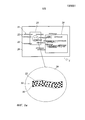
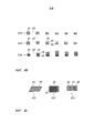
Фиг.1а показывает схематичное представление вида сверху защитного элемента с увеличенным фрагментом.Figa shows a schematic representation of a top view of a security element with an enlarged fragment.
Фиг.1b показывает схематичное представление увеличенного фрагмента защитного элемента по фиг.1а.Fig. 1b shows a schematic representation of an enlarged fragment of the security element of Fig. 1a.
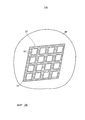
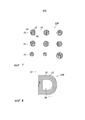
Фиг.2 показывает схематичное представление в разрезе фрагмента защитного элемента.Figure 2 shows a schematic sectional view of a fragment of a protective element.
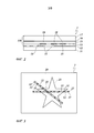
Фиг.3 показывает схематичный вид сверху защитного элемента.Figure 3 shows a schematic top view of a security element.
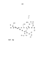
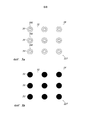
Фиг.4а-4с показывают, соответственно, схематичный вид сверху частичной области отражающего слоя защитного элемента.4a-4c show, respectively, a schematic top view of a partial region of the reflective layer of the security element.
Фиг.5а показывает схематичный вид сверху частичной области реплицирующего слоя защитного элемента.Fig. 5a shows a schematic top view of a partial region of a replicating layer of a security element.
Фиг.5b показывает схематичный вид сверху частичной области отражающего слоя защитного элемента.Fig. 5b shows a schematic top view of a partial region of the reflective layer of the security element.
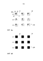
Фиг.6а показывает схематичный вид сверху частичной области реплицирующего слоя защитного элемента.6a shows a schematic top view of a partial region of a replicating layer of a security element.
Фиг.6b показывает схематичный вид сверху частичной области отражающего слоя защитного элемента.Fig.6b shows a schematic top view of a partial region of the reflective layer of the protective element.
Фиг.7 показывает схематичный вид сверху частичной области защитного элемента.7 shows a schematic top view of a partial region of a security element.
Фиг.8 показывает схематичный вид сверху частичной области отражающего слоя защитного элемента.Fig. 8 shows a schematic top view of a partial region of a reflective layer of a security element.
На фиг.1а показан защитный элемент 1, структура слоев которого показана для примера на фиг.2.On figa shows a
Защитный элемент 1 имеет слой 11 подложки, декоративный слой 12, опциональный клеящий слой 13, отражающий слой 14, опциональный реплицирующий слой 15, опциональный слой 16, а также опциональный слой 17. Наряду с этими слоями, защитный элемент 1 может включать в себя еще другие слои.The
Защитный элемент 1 предпочтительно образован защитным документом, в частности, ID-документом, например, паспортом, водительскими правами или картой доступа. Однако также возможно, что в случае защитного элемента 1 речь идет о ценном документе, например, банкноте, кредитной карте или тому подобном.The
Кроме того, предпочтительно, что защитный элемент образован многослойным телом, в особенности, в форме переводной пленки или ламинирующей пленки, которая включает в себя отражающий слой 14 и, в частности, не включает в себя декоративный слой 12 и слой 11 подложки. Так, например, защитный элемент 1 может быть выполнен как переводная пленка, которая включает в себя слои 17, 16, 15 и опционально клеящий слой 13. Кроме того, защитный элемент 1 также может быть образован ламинирующей пленкой, которая включает в себя слой 17, реплицирующий слой 15 и отражающий слой 14. Кроме того, защитный элемент 1 может также быть образован ламинирующей пленкой, которая имеет реплицирующий слой 15, который дополнительно служит в качестве несущего слоя, а также отражающий слой 14 и опциональный клеящий слой 13. Подобное многослойное тело, в особенности, предназначено для того, чтобы в качестве защитного элемента наноситься на один или несколько слоев ID-документа или ценного документа, или встраиваться между слоями ID-документа или ценного документа. Следующее описание слоев 13, 14, 15, 16 и 17 относится также к подобному выполнению защитного элемента 1.In addition, it is preferable that the protective element is formed by a multilayer body, in particular in the form of a transfer film or a laminating film, which includes a
Слой 11 подложки может, например, состоять из бумажной подложки или пластиковой подложки, или из последовательности нескольких, в особенности связанных в ламинат или экструдат, бумажных или пластиковых слоев. Слой 11 подложки имеет предпочтительно толщину слоя между 25 и 2000 мкм, более предпочтительно между 40 и 1000 мкм.The
Декоративный слой 12 состоит предпочтительно из одного или нескольких предпочтительно окрашенных слоев лака.The
Придание цвета декоративному слою 12 или образующим его слоям лака может, например, осуществляться посредством растворенных красителей или пигментов или комбинаций из красителей и пигментов. В частности, это могут быть флюоресцирующие в ультрафиолетовом излучении или возбуждаемые инфракрасным излучением красители или пигменты. Придание цвета декоративному слою 12 может также осуществляться посредством оптически переменных красителей или пигментов, так называемых OVI (оптически переменных красителей), то есть посредством красителей и/или пигментов, имеющих различные оптические представляемые изображения, в зависимости от ситуации наблюдения, например, в зависимости от угла наблюдения и/или угла подсветки.Coloring the
Эти слои лака сформированы для предоставления оптически воспринимаемой информации и представляют, таким образом, например, схематично показанные на фиг.1а оптические информации 23 и 24. Так декоративный слой 12, например, в области защитного элемента 1 выполнен в форме изображения владельца защитного элемента 1 как оптическая информация 23, и в другой области защитного элемента 1 в форме текста, определяющего владельца защитного элемента 1, например, включающего имя владельца, его адрес и/или его ID-номер. Кроме того, декоративный слой может также иметь не персонализированную или индивидуализированную информацию, как, например, один или несколько защитных оттисков. Слои лака декоративного слоя 12 состоят предпочтительно из одного или нескольких слоев лака, окрашенных отличающимся образом от слоя 11 подложки, и могут, наряду с красителями или «нормальными» красящими пигментами, также включать в себя создающие эффекты пигменты, как, например, пигменты тонкопленочного слоя, жидкокристаллические пигменты или металлические пигменты или ориентируемые посредством магнитных полей пигменты, создающие эффекты. При применении красящих пигментов в декоративном слое 12 также возможно, что информация 23 и 24 имеет оптически переменную представляемую картину, например, создают эффект смены цветов. Защитный оттиск может иметь оптически переменные компоненты и оптически не переменные компоненты. Защитный оттиск может, кроме того, содержать и другие, в частности, не оптические защитные признаки.These varnish layers are formed to provide optically perceptible information and thus represent, for example, the
Кроме того, также возможно, что декоративный слой 12 состоит из лазерно-чувствительного материала или включает в себя один или несколько слоев лазерно-чувствительного материала, в которые, например, записываются оптические информации 23 и/или 24 посредством лазера. Под лазерно-чувствительным материалом при этом понимается материал, который возбуждается под действием лазера для изменения цвета или за счет этого по меньшей мере частично и/или на участках удаляется.In addition, it is also possible that the
От декоративного слоя 12 и слоя 11 подложки можно также отказаться. Кроме того, также возможно, что между отражающим слоем 14 и декоративным слоем 12 еще размещены дополнительные или другие слои, такие как клеящий слой 13, или отражающий слой 14 следует непосредственно за декоративным слоем 12.The
Слои 13-17 могут, например, образовываться переводной пленкой 110 или переносимым слоем переводной пленки. В этом случае слой 16 образуется отделяемым слоем, а слой 17 - несущим слоем. Слои с 13 до 15 образуют тогда переводной слой, который после отрывания несущего слоя 17 и отделяемого слоя 16 остается на несущей подложке 11. При этом могут переноситься дополнительные, не показанные на фиг.2 слои, как, например, один или несколько защитных слоев, которые повышают стойкость по отношению к истиранию или химическим воздействиям. Также клеящий слой 13 может состоять из нескольких слоев, таких как, например, нижний (грунтовочный) слой и один или несколько слоев различных клеящих слоев. Другие дополнительно переносимые слои могут быть промежуточными слоями усилителя сцепления или барьерными слоями. Несущий слой 17 состоит в этом случае предпочтительно из пластиковой пленки, например, пленки полиэстера с толщиной слоя от 6 до 200 мкм. Пластиковая пленка может также, например, состоять из РЕТ (полиэтилентерефталат), PEN (полиэтиленнафталат) или BOPP (двухосно ориентированный полипропилен).Layers 13-17 can, for example, be formed by a
Далее, также возможно, что слои 13-17 образуют ламинирующую пленку. В этом случае слой 16 образован слоем усилителя сцепления, а слой 17 - слоем пластиковой пленки, который также может функционировать как защитный слой или как накрывающий слой защитного элемента 1. В этом случае слой 17 предпочтительно также выполнен из прозрачной пластиковой пленки с толщиной слоя от 6 до 200 мкм, предпочтительно из полиэстера, PET, BOPP или из поликарбоната (РС). Дополнительно или вместо слоев 16 и 17, защитный элемент 1 может включать в себя еще один или несколько других, предпочтительно прозрачных слоев, которые, например, также выполняют функцию покрывающего слоя для защиты от механических и/или химических воздействий в случае имеющего форму карты формообразования защитного элемента. Клеящий слой 13 предпочтительно состоит из клея для горячего склеивания, в частности, активируемого теплом термопластичного клея с толщиной слоя от 0,2 до 30 мкм. Реплицирующий слой 15 состоит предпочтительно из термопластичного реплицирующего лака с толщиной слоя от 0,2 до 10 мкм. В реплицирующем слое 15 посредством инструмента для тиснения формируется поверхностный рельеф 18 под действием тепла и давления. Кроме того, также возможно, что реплицирующий слой 15 состоит из UV-отверждаемого материала, и поверхностный рельеф 18 формируется путем UV-репликации в реплицирующем слое 15.Further, it is also possible that layers 13-17 form a laminating film. In this case, the
Вместо нескольких слоев 15, 16, 17 может иметься только один единственный слой, который выполняет несколько функций. Так, например, может осуществляться непосредственно реплицирование в полимерную пленку, и эта пленка с помощью клеящего слоя или без него присоединяется к защитному элементу. Подходящими материалами являются, например, РС или РЕТ. Типовые толщины слоя полимерной пленки лежат в диапазоне от 8 до 500 мкм, предпочтительно в диапазоне от 12 до 250 мкм, еще более предпочтительно в диапазоне от 20 до 150 мкм.Instead of
Отражающий слой 14 предпочтительно состоит из непрозрачного металлического слоя, например, из алюминия, меди, серебра, золота, хрома или сплава этих металлов. Под непрозрачным при этом понимается отражающий слой, пропускание которого в области видимого человеком-наблюдателем диапазона длин волн света менее 30%, предпочтительно менее 10%. Если отражающий слой 14 образован металлическим слоем, то толщина этого металлического слоя выбирается соответствующим образом, чтобы металлический слой образовывал непрозрачный отражающий слой согласно этому определению. Предпочтительным образом подобный металлический отражающий слой имеет толщину слоя более 10 нм, в особенности, больше, чем 15 нм.The
Кроме того, также возможно, что отражающий слой 14 состоит из нескольких слоев. Так, например, возможно, что отражающий слой 14 состоит из одного или нескольких диэлектрических отражающих слоев, например, последовательности высоко- и низкопреломляющих слоев (HRI- или LRI-слоев) или одного высоко- или низкопреломляющего слоя, который положен на непрозрачный слой для образования непрозрачного отражающего слоя.In addition, it is also possible that the
Кроме того, также возможно, что ниже или выше отражающего слоя 14 предусмотрен дополнительный диэлектрический отражающий слой, который предусмотрен, в особенности, по всей площади, только в области узора, только в фоновой области или только на участках, в которых отражающий слой 14 не предусмотрен.In addition, it is also possible that an additional dielectric reflective layer is provided below or above the
В качестве диэлектрических отражающих слоев здесь могут использоваться, например, слои из ZnS, TiO2, SiOx или MgF2, которые предпочтительно имеют толщину слоя от 25 до 2500 нм.As dielectric reflective layers, for example, layers of ZnS, TiO 2 , SiOx or MgF 2 , which preferably have a layer thickness of 25 to 2500 nm, can be used here.
Кроме того, также возможны полупроводящие слои, как, например, из Si, Ge, PbS, ZnSe, GaAs.In addition, semiconducting layers are also possible, such as, for example, from Si, Ge, PbS, ZnSe, GaAs.
Металлически действующие отражающие слои могут также наноситься посредством процесса печати, например, как тонко диспергированные в печатном лаке наночастицы или тонкие металлические чешуйки. Кроме того, отражающий слой может быть выполнен как фотонный кристалл.Metallically acting reflective layers can also be applied by means of a printing process, for example, as nanoparticles finely dispersed in a printing varnish or thin metal flakes. In addition, the reflective layer can be made as a photonic crystal.
В качестве непрозрачного слоя предпочтительно применяется непрозрачный слой лака, который имеет пропускающую способность менее 30% в диапазоне длин волн света, видимого человеком-наблюдателем. Этот слой лака наносится предпочтительно способом печати. Кроме того, слой лака может быть окрашен и, например, при отражении генерировать цветное представление.As the opaque layer, an opaque varnish layer is preferably used, which has a transmittance of less than 30% in the wavelength range of the light seen by a human observer. This varnish layer is preferably applied by printing. In addition, the varnish layer can be painted and, for example, when reflected, generate a color representation.
Кроме того, отражающий слой также может состоять из диэлектрического слоя или последовательности из нескольких диэлектрических слоев, которые покрыты металлическим слоем. За счет подходящего выбора слоев и их толщин могут быть реализованы особенно интересные цветовые эффекты, если диэлектрические слои выполнены прозрачными или просвечивающими.In addition, the reflective layer may also consist of a dielectric layer or a sequence of several dielectric layers that are coated with a metal layer. Due to the appropriate choice of layers and their thicknesses, particularly interesting color effects can be realized if the dielectric layers are made transparent or translucent.
Как показано на фиг.1а, защитный элемент 1 имеет область 21 узора, состоящую из нескольких элементов 22 композиции, и фоновую область 20, окружающую элементы 22 композиции. При этом элементы 22 композиции области узора могут иметь идентичное формообразование и повторяющийся узор. Кроме того, также возможно, что элементы композиции образуют взаимно дополняющееся содержание, например, фигурное представление или выполнены, например, в форме цифр, символов или букв для генерации оптически воспринимаемой информации. Кроме того, является особенно предпочтительным, что элементы композиции выполнены в форме линий, которые, например, образуют гильоши или сложный узор из линий, как это будет пояснено ниже более детально.As shown in FIG. 1 a, the
Предпочтительным образом, область 21 узора сформирована в форме микроскопически наблюдаемой композиции, то есть определяемое элементами 22 композиции формообразование области 21 узора является видимым для человека-наблюдателя с расстояния наблюдения примерно 30 см. Предпочтительным образом элементы 22 композиции области 21 узора имеют на каждом месте длину более 50 мкм, предпочтительно 300 мкм, и ширину более 5 мкм, предпочтительно более 10 мкм. Фоновая область 20 выполнена по меньшей мере с такими размерами, что область 21 узора - как изложено выше - распознается перед фоновой областью 20. Фоновая область 20 окружает, тем самым, с одной стороны, элементы 22 композиции, образованные из взаимосвязанной области, предпочтительно полностью, и имеет ширину и/или длину более 1 мм, предпочтительно более 2 мм. Элементы 22 композиции могут также быть ограничены кромкой защитного элемента 1 и не должны полностью окружаться фоновой областью 20.Preferably, the
К тому же могут иметься элементы композиции, которые полностью имеют отражающий слой или зоны, которые имеют наименьший размер более 300 мкм.In addition, there may be elements of the composition that fully have a reflective layer or zones that have a smallest size of more than 300 microns.
Фоновая область 20 может также быть образована одним или несколькими другими, образующими дополнительные защитные признаки, слоями, которые предпочтительно наносятся на отдельном технологическом этапе на слой 11 подложки. Эти другие слои могут быть индивидуализированными или персонализированными и/или иметь обычную голограмму, Kinegram®, которая имеет дифракционные структуры с одним или несколькими отражающими слоями на всей площади или на части площади, и/или объемную голограмму и/или трех- или многослойную тонкопленочную структуру (Фабри-Перо) и/или жидкокристаллический элемент. Кроме того, эти слои могут также иметь комбинации из вышеуказанных примеров и, тем самым, предоставлять, в частности, в фоновой области несколько защитных признаков.The
Отражающий слой 14 предусмотрен не в фоновой области 20, а предусмотрен в области узора в первых зонах 31, но не во вторых зонах 32. Первые зоны 31 при этом удалены друг от друга меньше, чем на 300 мкм, предпочтительно удалены друг от друга на расстояние от 25 до 250 мкм и имеют наименьший размер менее 300 мкм, предпочтительно от 5 до 100 мкм. Под наименьшим размером при этом понимается ширина первой зоны 31, то есть наименьшее расстояние между двумя краевыми точками зоны, которые лежат на общей прямой, проходящей через центр тяжести зоны.The
Кроме того, также возможно, что отражающий слой 14 в области 21 узора предусмотрен в инверсной форме и, таким образом, не предусмотрен в одной или нескольких первых зонах 31 и предусмотрен в одной или нескольких вторых зонах 32. При этом первые зоны 31, как описано выше, удалены друг от друга меньше, чем на 300 мкм, предпочтительно удалены друг от друга на расстояние от 25 до 250 мкм, и в этом отношении можно сослаться на приведенное выше описание.In addition, it is also possible that the
Предпочтительным образом величина площади первых зон, а также их интервал выбираются таким образом, что доля площади первых зон в области 21 узора и/или соответствующих первых зон на соответствующем декоративном элементе 22 составляет от 1 до 80%, особенно между 5 и 50%, например, 15%.Preferably, the size of the area of the first zones, as well as their interval, are selected so that the proportion of the area of the first zones in the
Так, например, в соответствующих элементах 22 композиции отражающий слой 14, как показано на фиг.1а, подразделен на первые зоны 31 точечной или прямоугольной формы, в которых предусмотрен отражающий слой 14, и который окружен второй зоной 32, в которой отражающий слой 14 не предусмотрен. В фоновой области 20, окружающей элемент 22 композиции, отражающий слой 14 не предусмотрен.So, for example, in the
Кроме того, также возможно, что в соответствующем элементе 22 композиции отражающий слой 14, как показано на фиг.1b, в первых зонах 31 точечной или прямоугольной формы не предусмотрен, причем они окружены второй зоной 32, в которой отражающий слой 14 предусмотрен. В фоновой области 20, окружающей элемент 22 композиции, отражающий слой не предусмотрен.In addition, it is also possible that in the
Кроме того, также возможно, что часть элементов 22 композиции выполнена согласно показанной на фиг.1а конфигурации, и часть элементы 22 композиции защитного элемента 1 выполнена в конфигурации, показанной на фиг.1b. Также возможно, что защитный элемент 1, с одной стороны, имеет один или несколько элементов 22 композиции, в области 21 узора которых отражающий слой 14 предусмотрен в первых зонах 31, но не предусмотрен в одной или нескольких вторых зонах 32, и предусмотрены один или несколько элементов 22 композиции, в области 21 узора которых отражающий слой 14 предусмотрен в одной или нескольких вторых зонах 32, но не в первых зонах 31.In addition, it is also possible that part of the
За счет такого выполнения отражающего слоя 14 достигается то, что элемент 22 композиции является еще достаточно прозрачным, чтобы оптически воспринимаемая информация, предусмотренная под элементами 22 композиции, была видимой через по существу непрозрачный отражающий слой 14, что, кроме того, эта информация накладывается тогда на наблюдаемую в отражении информацию, которая определяется посредством формования области 21 узора, а также поверхностного рельефа 18.Due to this embodiment of the
Как представлено на фиг.2, поверхностный рельеф 18 ориентирован предпочтительно с приводкой, то есть точно по положению к первым зонам 31. Отражающий слой 14 и поверхностный рельеф 18 за счет этого образуются посредством выполненных с приводкой друг к другу процессов. Такие приведенные процессы означают, что относительные положения, в частности, отражающего слоя 14 с узором и, в частности, поверхностного рельефа 18 с узором ориентируются по отношению друг к другу во время отдельных этапов процесса, например, с помощью, в частности, оптически детектируемых меток приводки, точно по положению. Предпочтительным образом, за счет этого достигается то, что в фоновой области 20 и/или в одной или нескольких вторых зонах 32 поверхностный рельеф 18 не формируется, или там предусмотрен поверхностный рельеф 18, который отличается от поверхностного рельефа 18, сформированного в зонах 31, особенно по своему характеристическому отношению от поверхностного рельефа 18 на по меньшей мере 50%.As shown in FIG. 2, the
Особым преимуществом, таким образом, является, когда структуры рельефа, определяющие оптически переменное представляемое изображение области 21 узора, формируются только в зонах 31 реплицирующего слоя 15, и, в частности, при изготовлении защитного элемента 1 формирование и расположение зон 31 осуществляется в зависимости от поверхностного рельефа 18, предусмотренного для соответствующего оптически переменного эффекта.A particular advantage, therefore, is when the relief structures defining the optically variable representation of the image of the
Для изготовления защитного элемента 1, таким образом, например, на несущую положку 17 сначала наносится удаляемый слой или слой 16 усилителя сцепления по всей площади, например, с помощью печати, затем на всей площади наносится, например, посредством печати, реплицирующий слой 15, и затем в области первых зон 31 формируется поверхностный рельеф 18, как уже описано выше, в реплицирующем слое 15. Затем предпочтительно с приводкой к этому, то есть точно по положению, наносится или структурируется отражающий слой 14. Для этого, например, возможно, что отражающий слой 14 наносится по всей площади, например, с помощью испарения или напыления, и затем посредством позитивного или негативного травления, посредством метода промывки, посредством механической абляции или посредством лазерной абляции в области вторых зон 32, а также в фоновой области 20 вновь удаляется. Кроме того, также возможно, что, например, посредством маски для напыления, отражающий слой 14 наносится только в области первых зон 31. Но отражающие слои могут также наноситься посредством процесса печати локальным образом. При этом материал отражающего слоя, например, диспергируется в печатном лаке, или отражающий слой формируется в химической или физической реакции при и/или после печати, и локально нанесенный отпечаток служит только для установления непрозрачных областей, например, путем локального осаждения. Кроме того, также возможно, что для приводки этих процессов, то есть для достижения точности по положению процессов в первых зонах 31, с одной стороны, и во вторых зонах 32 и фоновой области 20, с другой стороны, формируются различные структуры рельефа, свойства которых используются в особенности для точного по положению структурированного отражающего слоя 14.To manufacture the
На фиг.2 показана структура, в которой реплицирующий слой 15 лежит между отражающим слоем 14 и наблюдателем. Последовательность слоев может, однако, быть и обратной, то есть отражающий слой 14 может лежать между реплицирующим слоем 15 и наблюдателем. Во многих выполнениях непрозрачный отражающий слой 14 является достаточно тонким и поэтому следует с достаточной точностью поверхностному рельефу, так что поверхностный рельеф при наблюдении с обеих сторон оказывает оптическое воздействие.Figure 2 shows the structure in which the
Если, как изложено выше, в качестве отражающего слоя 14 используется многослойная последовательность слоев из одного или нескольких прозрачных или просвечивающих диэлектрических отражающих слоев и непрозрачного слоя, то также возможно, что диэлектрический отражающий слой предусмотрен на всей площади защитного элемента, и только структурирование или структурированное нанесение непрозрачного слоя осуществляется так, что отражающий слой 14 в области первых зон 31 образует непрозрачный отражающий слой, а во вторых зонах 32 образует прозрачный или просвечивающий отражающий слой. Другой предпочтительный вариант состоит в том, что непрозрачный металлический отражающий слой предусмотрен в зонах 31 и что в качестве другого отражающего слой 14 имеется в значительной степени прозрачный HRI-слой частично или на всей площади в фоновой области 20.If, as described above, a multilayer sequence of layers of one or more transparent or translucent dielectric reflective layers and an opaque layer is used as the
Поверхностный рельеф 18 составлен предпочтительно из одной или нескольких структур рельефа, которые выбраны из группы, включающей в себя дифракционную решетку, голограмму, отражательную рельефно-фазовую дифракционную решетку, линейную решетку, кроссрешетку, гексагональную решетку, асимметричную или симметричную решетчатую структуру, ретроотражательную структуру, преломляющие или дифракционные микролинзы, преломляющие или дифракционные микропризмы, дифракционные структуры нулевого порядка, структуру типа глаза мотылька, или анизотропную или изотропную матовую структуру, или наложение двух или более из названных структур рельефа. Так, например, возможно, что в различных областях первых зон 31 предусмотрены различные структуры рельефа или в различных первых зонах предусмотрены различные структуры рельефа или в различных элементах 22 композиции различные структуры рельефа. Тем самым возможно достичь того, что различные элементы композиции показывают различное оптически переменное представляемое изображение, что различные участки области 21 узора или различные участки элементов 22 композиции показывают различные цвета или различную яркость, или что тем самым могут генерироваться оптически переменные эффекты, которые, например, не могут имитироваться посредством голографического поверхностного рельефа.The
Наблюдение защитного элемента 1 осуществляется согласно направлению наблюдения.The observation of the
При изготовлении защитного элемента 1 декоративный слой 12 наносится, например, на слой положки 11 посредством способа печати, и затем переводная пленка 110 прикладывается к поверхности слоя 11 подложки с нанесенным печатью декоративным слоем 12. Кроме того, также возможно, что декоративный слой 12 наносится печатью на клеящий слой 13 или на реплицирующий слой 15. Кроме того, также возможно, что персонализированные информации 23 и 24 после изготовления защитного элемента 1 или во время изготовления защитного элемента 1 посредством лазера записываются в декоративный слой 12, причем здесь предпочтительно лазер расположен на стороне отражающего слоя 14, противолежащей декоративному слою 12.In the manufacture of the
Фиг.3 показывает фрагмент защитного элемента 2. Защитный элемент 2 имеет при этом фоновую область 20 и область 21 узора, которая образована несколькими элементами 22 композиции в форме линий, из которых на фиг.3 для примера представлены фрагменты двух элементов 22 композиции. Структура слоев защитного элемента 2 соответствует структуре слоев защитного элемента 1, ив этом отношении здесь можно сослаться на предыдущее описание защитного элемента 1.Figure 3 shows a fragment of the
Защитный элемент 2 имеет также оптическую информацию 25, которая предоставляется расположенным под отражающим слоем 14 декоративным слоем 12, и которая, как показано на фиг.3, перекрывает частично фоновую область 20, а также область 21 узора.The
Область 21 узора имеет в случае защитного элемента 2, как уже изложено выше, два или более элемента 22 композиции, которые выполнены в форме линий. Под линией здесь понимается элемент композиции, ширина которого по меньшей мере с коэффициентом 10 меньше, чем его длина. Предпочтительным образом ширина линий составляет от 5 до 250 мкм, например, ширина линий составляет 50 мкм. Как показано на фиг.3, элементы 22 композиции в форме линий имеют первые зоны 31 и вторые зоны 32, которые расположены согласно одномерному растру вдоль продольного направления соответствующих линий. Таким образом, предусматривается соответственно только одна первая зона 31 по ширине соответствующей линии. В примере выполнения на фиг.3 соответствующая первая зона 31 занимает всю ширину линий, таким образом, ширина первых зон 31 соответствует ширине соответствующей линии. Как представлено на фиг.3, ширина соответствующих первых зон 31 постоянна и составляет, например, от 5 до 250 мкм, более предпочтительно от 10 до 100 мкм. Интервал между ними варьируется, за счет чего для человека-наблюдателя яркость этих элементов композиции вдоль линии варьируется. При этом первые зоны 31, как описано выше, а также далее со ссылками на фиг.4а, фиг.4с или фиг.6а-7, покрыты поверхностными структурами поверхностного рельефа 18. Однако также возможно отказаться от формирования поверхностного рельефа 18 в первых зонах 31.The
Фиг.4а показывает для примера фрагмент защитного элемента 3, который построен согласно защитному элементу 2 и защитному элементу 1. Относительно структуры защитного элемента 3 можно сослаться на предыдущее описание фиг.1-3. При этом, как представлено на фиг.4а, область 21 узора имеет элементы 22 композиции также линейной формы, из которых на фиг.4а для примера показаны три элемента 221, 222, 223 композиции. Элементы 221-223 композиции имеют соответственно последовательность первых зон 31 и вторых зон 32, как это показано на фиг.4а. При этом первые зоны 31 элементов 221, 222, 223 композиции покрыты соответственно различающимися структурами рельефа, как это показано на фиг.4а различной штриховкой этих зон.Fig. 4a shows, for example, a fragment of the
При этом разделение элементов 221-223 композиции на первые зоны и вторые зоны в каждом из элементов 221-223 композиции индивидуально согласуется, так что не возникают никакие мешающие эффекты, как, например, муаровый узор или повышенное преломление. Расстояния между первыми зонами 31 по отношению друг к другу выбираются таким образом, что наблюдатель распознает три непрерывных линии невооруженным глазом. Например, расстояния между первыми зонами 31 по отношению друг к другу составляют менее 300 мкм.Moreover, the separation of the elements 221-223 of the composition into the first zones and second zones in each of the elements 221-223 of the composition is individually consistent, so that there are no interfering effects, such as a moire pattern or increased refraction. The distances between the
Расстояния между зонами 31, их форма и величина могут при этом варьироваться вдоль линии. При этом критериями для выполнения первых зон являются, например, исключение мешающих коллизий с другими смежными элементами 22 композиции или исключение муаровых помеховых эффектов для лежащей под ними оптической информации, например, оптической информации, предоставленной декоративным слоем 12.The distances between
При этом при применении элементов 22 композиции в форме линий является особенно предпочтительным, если расположение и формирование первых зон, а также их покрытие структурами рельефа поверхностного рельефа 18 выполнены согласно фиг.4а-4с. Подобные элементы 22 композиции могут, например, использоваться в защитном элементе 1 по фиг.1 или в защитных элементах 2 и 3 по фиг.3 или фиг.4.Moreover, when applying the elements of the
Фиг.4b показывает три различных возможности выполнения элементов 22 композиции в форме линий. На фиг.4b показаны три элемента 224, 225 и 226 композиции в форме линий. Элементы 224-226 композиции выполнены соответственно в форме линии, как это, например, было описано выше для элемента 22 композиции защитного элемента 2.Fig. 4b shows three different possibilities for making the
Элемент 224 композиции имеет последовательность первых зон 31, которые отделены соответствующими вторыми зонами 32. Вдоль линии здесь варьируется величина первых зон 31, чтобы сформировать локально различающуюся интенсивность, в особенности, оптически переменного эффекта. Как показано на фиг.4b, здесь варьируется протяженность первых зон 31 в направлении ширины линии, причем протяженность первых зон 31 в продольном направлении линии и/или расстояние между первыми зонами 31 вдоль линии является постоянным. Исследования показали, что за счет этого яркость элемента композиции вдоль линии может варьироваться, не искажая яркость нижележащей информации в области вдоль линии.The
В элементе 225 композиции площадь поверхности первых зон 31 вдоль линии выбрана постоянной. Первые зоны 31 здесь разделены на две частичные зоны 33 и 34, и при этом только частичные зоны 34 покрыты структурами рельефа поверхностного рельефа 18, а частичные зоны 33 не покрыты поверхностным рельефом или образуют зеркальные поверхности. Как представлено на фиг.4b, при этом варьируется величина площади частичных зон 33 и 34 вдоль линии, в то время как величина площади зон 31 остается постоянной. Так среднее пропускание элемента 225 композиции вдоль линии остается постоянным, а яркость в различных направлениях наблюдения и/или цвет элемента 225 композиции варьируется вдоль линии. Кроме того, здесь также возможно, что первые зоны 31 разделены на более чем две частичных зоны, которые покрыты различными структурами рельефа, как это поясняется ниже со ссылками на фиг.4с, фиг.6а и фиг.7.In the
Элемент 226 композиции имеет также первые зоны 31, которые разделены на две частичных зоны 34 и 35, которые покрыты различными структурами рельефа.The
Целенаправленная вариация локальной плотности площади, то есть протяженность по площади первых зон 31 и их интервал, а также покрытие первых зон 31 структурами рельефа может использоваться для того, чтобы представлять дополнительную информацию. Так наблюдатель может в зеркальном отражении распознавать, например, макроскопическую информацию изображения или текст, и при этом на представление в дифракционном оптическом признаке не оказывается влияния. Эта дополнительная информация может также состоять в признаке поляризации, который распознается только при наблюдении через соответствующий фильтр.A targeted variation of the local area density, that is, the extent over the area of the
К тому же интервалы и величина площади первых зон 31 могут соответствующим образом варьироваться, так что наблюдатель распознает первый дифракционный признак, а при наблюдении через соответствующий фильтр становится видимым независимый от него муаровый узор. Как уже упомянуто выше, здесь можно, например, путем отклонения величины площади и/или расстояния от соответствующего расположения непрозрачных плоскостей или линз муарового верификационного элемента, кодировать скрытую информацию, которая становится видимой только при суперпозиции с муаровым верификационным элементом.Moreover, the intervals and the size of the area of the
Дополнительно также расположение первых зон 31 относительно друг друга и/или расположение структур рельефа внутри соответствующей первой зоны 31 может использоваться для кодирования дополнительной информации.Additionally, the location of the
Фиг.4с показывает для примера несколько дополнительных возможностей подразделения первых зон 31 на частичные зоны, которые покрыты различными структурами рельефа. Так фиг.34с показывает первую зону 311, которая разделена на частичные зоны 34 и 35, первую зону 312, которая разделена на частичные зоны 34 и 35, и первую зону 313, которая разделена на частичные зоны 34, 35 и 36. Частичные зоны 34, 35 и 36 покрыты различными структурами рельефа. При этом, например, частичная зона 34 расположена на дифракционной решетке, которая генерирует динамическую цветную кинеграмму (Kinegram®), а частичная зона 35 покрыта анизотропно рассеивающей матовой структурой. Так, например, с одного направления наблюдения элемент композиции, снабженный первыми зонами 311, может показывать динамическую цветную кинеграмму, в то время как с другого направления наблюдения распознается статический ахроматический признак с тем же графическим содержанием. В первых зонах 313 предусмотрено три частичных зоны, которые, например, под различными направлениями наблюдения показывают различный оптический признак, или также покрыты решетчатыми структурами, которые показывают различный цвет и, тем самым, обеспечивают возможность формирования изображения натурального цвета в области 21 узора, причем относительная доля площади частичных зон 34, 35 и 36 определяет цветовой тон, и величина площади первых зон 313 определяет соответствующую локальную яркость (интенсивность).Fig. 4c shows, by way of example, several additional possibilities for dividing the
Посредством выполнения и расположения первых зон 31, как описано выше на основе фиг.4а-4с, становится возможным выполнить элементы 22 композиции линейной формы, которые вдоль линии в различных направлениях наблюдения создают отличающееся оптическое представление и/или локально отличающийся цвет и/или локально отличающуюся яркость и/или прозрачность. Применение элементов композиции линейной формы, которые, как описано выше, имеют расположенные вдоль линии первые зоны 31, обеспечивает возможность контрастного по контуру представления тонких линий в области узора, которые с равномерным формированием растра отражающего слоя и без приводки к нему, то есть с неточным по положению покрытием структурами рельефа, предусмотренными на участках линейной формы, лишь в недостаточной степени могли бы имитироваться. Таким образом, обеспечивается защитный элемент, который лишь с трудом поддается подделке и манипулированию.By making and arranging the
Другая возможность расположения первых зон 31 в элементе 22 композиции и соответствующего этому расположения структур рельефа поверхностного рельефа 18 поясняется в качестве примера на основе фиг.5а и фиг.5b.Another possibility of arranging the
Фиг.5а и фиг.5b иллюстрируют, с одной стороны, выполнение поверхностного рельефа, сформированного в реплицирующем слое 18, или структурирование отражающего слоя 14 в частичной области элемента 227 композиции.FIGS. 5a and 5b illustrate, on the one hand, the implementation of a surface pattern formed in the
Как указано на фиг.5b, при этом предусмотрены первые зоны 31, которые покрыты непрозрачным отражающим слоем 14 и которые окружены второй зоной 32. С приводкой, то есть точно по положению к этому, как показано на фиг.5а, в реплицирующем слое 18 в первых зонах 31 сформированы микролинзы 181. Эти микролинзы могут быть сформированы как преломляющие линзы или как дифракционные линзы. Как показано на фиг.5а и фиг.5b, структурирование металлического слоя 14 осуществляется при этом с точной приводкой, то есть точно по положению к линзам 181, так что каждая линза 181 полностью покрыта отражающим слоем 14, а окружающие области являются полностью прозрачными или просвечивающими. За счет согласования первых зон с формообразованием линз 181 и выполненного с приводкой, то есть точного по положению расположения линз 181 относительно отражающего слоя 14 становится возможным, по сравнению с расположением без приводки, то есть неточным по положению, повысить прозрачность элемента 227 композиции или улучшить контраст защитного признака.As indicated in FIG. 5b,
Фиг.6а и 6b иллюстрируют другую возможность формообразования и расположения первых зон 31 и структуры рельефа поверхностного рельефа 18 по отношению друг к другу. Фиг.6а иллюстрирует расположение структур рельефа, сформированных в реплицирующем слое 18, и фиг.6b - расположение и формообразование первых зон в отражающем слое 14 в частичной области элемента 228 композиции.6a and 6b illustrate another possibility of shaping and arranging the
Зоны 31 расположены здесь в форме равномерного двумерного растра и в форме прямоугольников. Также возможно, что растр при этом не является равномерным, и в частности, согласован с контуром элемента 228 композиции. Зоны 31 могут также иметь другое формообразование или варьироваться по их величине площади, как это описано выше по отношению к элементам композиции линейной формы.
Каждая из первых зон 31 здесь разделена на четыре частичных зоны, а именно, частичные зоны 34, 35, 36 и 37, которые, как упомянуто выше, могут иметь различные структуры рельефа. Заполнение частичной зоны 34 структурой 182 рельефа показано на фиг.6а для примера.Each of the
Структуры рельефа в частичных зонах 34-37 служат, например, для того, чтобы представлять четыре различных содержания, которые, например, являются видимыми в различных направлениях наблюдения. При этом частичные зоны могут иметь, например, дифракционные структуры рельефа, например, дифракционные решетки, преломляющие структуры рельефа или также рассеивающие структуры рельефа, или также зеркальные площадки. Так, например, каждая зона 31, как показано на фиг.6а, разделена на четыре частичные зоны, причем каждая из частичных зон ассоциирована с соответствующим направлением наблюдения, и покрытие соответствующих частичных зон соответствует, например, информации яркости изображения, распознаваемого в ассоциированном направлении наблюдения.The relief structures in partial zones 34-37 serve, for example, to represent four different contents, which, for example, are visible in different directions of observation. In this case, partial zones can have, for example, diffraction relief structures, for example, diffraction gratings, refracting relief structures or also scattering relief structures, or also mirror sites. So, for example, each
Как уже описано выше, первые зоны 31 в этом примере выполнения предпочтительно разнесены на расстояние от 25 до 250 мкм друг от друга, и размеры первых зон 31 предпочтительно лежат в диапазоне от 5 до 100 мкм. Коэффициент заполнения, то есть покрытие элементов 228 композиции первыми зонами 31, составляет при этом предпочтительно 15%, так что 85% площади остаются прозрачными.As already described above, the
Фиг.7 показывает фрагмент элемента 229 композиции. Элемент 229 композиции имеет первые зоны 31, которые отделены друг от друга вторыми зонами 32. Как показано на фиг.7, величина площади первых зон 31 варьируется локально, так что здесь, как изложено выше для элементов композиции линейной формы, локальная общая интенсивность или яркость области узора варьируется. Кроме того, первые зоны 31 разделены на частичные зоны 34, 35 и 36. В частичных зонах 34, 35 и 36 предусмотрены различные структуры рельефа, например, дифракционные решетки, которые имеют различную пространственную частоту или различный азимутальный угол. Как показано на фиг.7, за счет этого варьируется, наряду с площадью поверхности зон 31, также относительная величина площади зон 34, 35 и 36 по отношению друг к другу. Если в качестве структур рельефа в частичных зонах 34, 35 и 36 формируются, например, структуры рельефа, которые создают различное цветовое представление, то за счет относительной доли площади частичных зон 34-36 друг к другу может устанавливаться получаемый в итоге цвет, а за счет величины площади зон 31 - яркость или интенсивность. За счет этих мер является возможным локально в элементе композиции варьировать цвет и яркость и, тем самым, например, предоставлять изображение натурального цвета, которое в качестве первой информации накладывается на индивидуализированную вторую информацию.7 shows a fragment of an
Фиг.8 показывает схематичное представление элемента 230 композиции области 21 узора, которая имеет первые зоны 31 линейной формы, которые отделены друг от друга посредством вторых зон 32. Кроме того, элемент 230 композиции окружен фоновой областью 20.FIG. 8 shows a schematic representation of a
Как представлено на фиг.8, первые зоны 31 выполнены как параллельные линии, которые следуют внешнему и внутреннему контуру элемента 230 композиции. Ширина этих линий составляет предпочтительно от 5 до 250 мкм, боле предпочтительно от 10 до 100 мкм. Элемент 230 композиции предпочтительно представляет собой элемент композиции, ширина и/или высота которого больше, чем 1 мм, предпочтительно больше, чем 2 мм. Элемент 230 композиции, как показано на фиг.8, выполнен, например, как буква. Однако элемент 230 композиции может иметь и другое формообразование, например, быть выполнен в форме другой буквы или числа, или фигурного представления, герба или пиктограммы. При этом также возможно, что элемент композиции имеет одну или несколько линий, которые следуют внутреннему и/или внешнему контуру, или также другие линии, которые расположены не параллельно внутреннему и/или внешнему контуру и которые, например, обеспечивают возможность согласования с внутренним контуром, отличающимся от внешнего контура. Кроме того, также возможно, что первые зоны 31 линейной формы имеют различную ширину и создают визуально распознаваемое фигурное представление, например, на основе модуляции ширины первых зон 31 линейной формы, или что первые зоны 31 линейной формы на участках прерываются равномерно, неравномерно или стохастически и не образуют, как представлено на фиг.8а, соответствующей замкнутой линии. Направление линии может, однако, прокладываться полностью независимо от внешней формы элемента 230 композиции и состоять, например, из параллельных или концентричных линий. Особенно предпочтительными являются средние перекрытия площади в диапазоне от 5% до 40%, так как они обеспечивают как достаточное отражение, так и высокое пропускание. Кроме того, предпочтительными являются расстояния между линиями в диапазоне от 10 до 200 мкм.As shown in FIG. 8, the
Вместо линий элемент 230 композиции также может содержать отражающий слой в форме мелкого текста или фигурных представлений, символов, букв, чисел или логотипов. Детали открываются наблюдателю только при наблюдении с помощью вспомогательного средства, например лупы или микроскопа. Распознаваемые наблюдателем невооруженным глазом локальные распределения яркости могут подвергаться влиянию, например, посредством величины текста, шрифта (типа шрифта), разнесения букв или покрытия микроструктурами.Instead of lines,
И здесь является особенно предпочтительным, как изложено выше, если поверхностный рельеф 18 предусмотрен с точной приводкой к зонам 31. Кроме того, поверхностный рельеф может здесь дополнительно иметь частичные зоны вдоль первых зон 31 линейной формы, которые покрыты различными структурами рельефа, чтобы генерировать обсужденные выше эффекты.And here it is especially preferred, as described above, if the
Защитный элемент 1 может дополнительно иметь область 21 узора, которая имеет различные элементы 22 композиции. Так, например, могут друг с другом комбинироваться один или несколько элементов композиции, которые выполнены согласно фиг.3-4с, один или несколько элементов композиции, которые выполнены согласно элементу 227 композиции, один или несколько элементов композиции, которые выполнены как элементы 228 или 229 композиции, и/или один или несколько элементов композиции, которые выполнены как элемент 230 композиции. Посредством таких комбинаций различных элементов композиции может предоставляться защитный элемент, который характеризуется особенно высокой стойкостью к подделкам.The
Claims (32)
и защитный элемент (1) имеет декоративный слой (12) для генерации второй оптически воспринимаемой информации (23, 24, 25), который перекрывает как область (21) узора, так и фоновую область (20) по меньшей мере на участках, декоративный слой (12) по отношению к направлению (10) наблюдения защитного элемента (1) расположен под непрозрачным отражающим слоем (14), и все слои (13) защитного элемента, расположенные между непрозрачным отражающим слоем (14) и декоративным слоем (12), являются прозрачными или просвечивающими. 1. The security element (1), especially a valuable document, with a region (21) of the pattern consisting of one or more elements (22) of the composition, the formation of which provides the first optically perceptible information, and a background region (20) surrounding at least sections one or more composition elements of the pattern area, and the protective element (1) has an opaque reflective layer (14), which is provided in the first areas (31) of the pattern area (21) or is provided in one or more second zones (32) of the pattern area ( 21), and the first zones s (31) are spaced less than 300 μm apart and have a smallest size of less than 300 μm,
and the protective element (1) has a decorative layer (12) for generating the second optically perceptible information (23, 24, 25), which covers both the region (21) of the pattern and the background region (20) at least in areas, the decorative layer (12) with respect to the observation direction (10) of the protective element (1) is located under the opaque reflective layer (14), and all layers (13) of the protective element located between the opaque reflective layer (14) and the decorative layer (12) are transparent or translucent.
предоставление прозрачной переводной пленки (110) с областью, которая разделена на область узора, формообразование которой предоставляет первую информацию, и фоновую область (20), окружающую по меньшей мере на участках область узора,
формирование в переводной пленке (110) непрозрачного отражающего слоя (14), который предусмотрен в первых зонах (31) области узора (21) или предусмотрен в одной или нескольких вторых зонах (32) области узора (21), причем первые зоны (31) разнесены менее чем на 300 мкм друг от друга и имеют наименьший размер менее 300 мкм,
нанесение переводной пленки на подложку (11) таким образом, что между переводной пленкой (110) и подложкой (11) располагается персонализированный декоративный слой (12), который предоставляет вторую оптически воспринимаемую информацию (23, 24, 25),
причем декоративный слой (12) перекрывает как область (21) узора, так и фоновую область (20) по меньшей мере на участках, декоративный слой (12) по отношению к направлению (10) наблюдения защитного элемента (1) расположен под непрозрачным отражающим слоем (14), и все слои (13) защитного элемента, расположенные между непрозрачным отражающим слоем (14) и декоративным слоем (12), являются прозрачными или просвечивающими.30. A method of manufacturing a protective element (1), in particular a valuable document, comprising the following steps:
providing a transparent transfer film (110) with a region that is divided into a region of the pattern, the formation of which provides the first information, and a background region (20) surrounding at least in regions the region of the pattern,
the formation in the transfer film (110) of an opaque reflecting layer (14), which is provided in the first zones (31) of the pattern area (21) or is provided in one or more second zones (32) of the pattern region (21), the first zones (31) spaced less than 300 microns apart and have a smallest size of less than 300 microns,
applying the transfer film to the substrate (11) in such a way that between the transfer film (110) and the substrate (11) there is a personalized decorative layer (12) that provides the second optically perceptible information (23, 24, 25),
moreover, the decorative layer (12) overlaps both the region (21) of the pattern and the background region (20) at least in areas, the decorative layer (12) with respect to the direction (10) of observation of the protective element (1) is located under an opaque reflective layer (14), and all layers (13) of the security element located between the opaque reflective layer (14) and the decorative layer (12) are transparent or translucent.
предоставление защитного элемента по любому из пп. 1-29,
запись персонализированной информации с помощью лазера в лазерно-чувствительный декоративный слой, расположенный под непрозрачным отражающим слоем, причем при записи непрозрачный отражательный слой расположен между лазером и декоративным слоем (12).31. A method of manufacturing a protective element (1), in particular a valuable document, comprising the following steps:
the provision of a protective element according to any one of paragraphs. 1-29,
recording personalized information using a laser in a laser-sensitive decorative layer located under an opaque reflective layer, and when recording an opaque reflective layer is located between the laser and the decorative layer (12).
Applications Claiming Priority (3)
| Application Number | Priority Date | Filing Date | Title |
|---|---|---|---|
| DE102010050031A DE102010050031A1 (en) | 2010-11-02 | 2010-11-02 | Security element and method for producing a security element |
| DE102010050031.3 | 2010-11-02 | ||
| PCT/EP2011/005489 WO2012059208A2 (en) | 2010-11-02 | 2011-10-31 | Security element and method for producing a security element |
Publications (2)
| Publication Number | Publication Date |
|---|---|
| RU2013125471A RU2013125471A (en) | 2014-12-10 |
| RU2596447C2 true RU2596447C2 (en) | 2016-09-10 |
Family
ID=44913230
Family Applications (1)
| Application Number | Title | Priority Date | Filing Date |
|---|---|---|---|
| RU2013125471/12A RU2596447C2 (en) | 2010-11-02 | 2011-10-31 | Protective element and method of making protective element |
Country Status (17)
| Country | Link |
|---|---|
| US (1) | US20130285361A1 (en) |
| EP (1) | EP2635444B1 (en) |
| JP (1) | JP5979506B2 (en) |
| CN (1) | CN103370206B (en) |
| AU (1) | AU2011325516B2 (en) |
| BR (1) | BR112013010547B1 (en) |
| DE (1) | DE102010050031A1 (en) |
| ES (1) | ES2720956T3 (en) |
| HR (1) | HRP20190873T1 (en) |
| HU (1) | HUE044069T2 (en) |
| MX (1) | MX2013004875A (en) |
| PL (1) | PL2635444T3 (en) |
| RS (1) | RS58616B1 (en) |
| RU (1) | RU2596447C2 (en) |
| SI (1) | SI2635444T1 (en) |
| TR (1) | TR201907122T4 (en) |
| WO (1) | WO2012059208A2 (en) |
Cited By (1)
| Publication number | Priority date | Publication date | Assignee | Title |
|---|---|---|---|---|
| RU2687409C1 (en) * | 2018-10-25 | 2019-05-13 | Акционерное общество "ГОЗНАК" | Protective element |
Families Citing this family (32)
| Publication number | Priority date | Publication date | Assignee | Title |
|---|---|---|---|---|
| DE102012105571B4 (en) | 2012-06-26 | 2017-03-09 | Ovd Kinegram Ag | Decorative element as well as security document with a decorative element |
| WO2014011172A1 (en) * | 2012-07-12 | 2014-01-16 | Datacard Corporation | Secure identification document with ablated foil element |
| WO2014086715A1 (en) * | 2012-12-04 | 2014-06-12 | Sectago Gmbh | Security device |
| CA2898797C (en) * | 2013-02-12 | 2021-02-02 | Sectago Gmbh | Security device |
| EP3427968B2 (en) | 2013-03-12 | 2023-03-01 | Toppan Printing Co., Ltd. | Display |
| TW201502257A (en) * | 2013-07-10 | 2015-01-16 | Sicpa Holding Sa | Marking comprising a printable code and a chiral liquid crystal polymer layer |
| DE102013108666A1 (en) * | 2013-08-09 | 2015-03-05 | Leonhard Kurz Stiftung & Co. Kg | Method for producing a multilayer body and multilayer body |
| US10207531B2 (en) | 2013-12-02 | 2019-02-19 | SECTAG GmbH | Security device |
| FR3021583B1 (en) * | 2014-05-30 | 2021-10-22 | Hologram Ind | CUSTOMIZABLE SAFETY OPTICAL COMPONENT FOR THE MANUFACTURE OF A PERSONALIZED SAFETY DOCUMENT AND MANUFACTURE OF SUCH COMPONENT |
| RU2557620C1 (en) * | 2014-06-02 | 2015-07-27 | Федеральное Государственное Унитарное Предприятие "Гознак" (Фгуп "Гознак") | Multilayer polymer structure and method of making same |
| AT515845B1 (en) * | 2014-06-10 | 2017-05-15 | Hueck Folien Gmbh | Security element and method for producing a security element with light-scattering structures |
| US10195890B2 (en) * | 2014-09-16 | 2019-02-05 | Crane Security Technologies, Inc. | Secure lens layer |
| DE102015100520A1 (en) * | 2015-01-14 | 2016-07-28 | Leonhard Kurz Stiftung & Co. Kg | Multilayer body and method for its production |
| DE102015202252A1 (en) * | 2015-02-09 | 2016-08-11 | Bundesdruckerei Gmbh | Value or security product and method for its production with decentralized individualization |
| DE102015207268A1 (en) * | 2015-04-22 | 2016-10-27 | Tesa Scribos Gmbh | Security element and method for producing a security element |
| CN107615111B (en) * | 2015-06-02 | 2021-09-28 | 凸版印刷株式会社 | Laminate and method for producing same |
| WO2017006958A1 (en) * | 2015-07-07 | 2017-01-12 | 凸版印刷株式会社 | Percutaneous administration device |
| AU2016307053A1 (en) * | 2015-08-07 | 2018-03-01 | Rolic Technologies AG | Azimuthally modulated scattering device |
| CN105096738A (en) * | 2015-09-11 | 2015-11-25 | 武汉威杜信息科技有限公司 | Anti-counterfeiting method |
| CN107433817A (en) * | 2016-05-27 | 2017-12-05 | 苏州苏大维格光电科技股份有限公司 | A kind of decorating film and ambetti |
| DE102017106545A1 (en) * | 2017-03-27 | 2018-09-27 | Ovd Kinegram Ag | A method for producing an optical security feature and a security element and a security document |
| DE102017106721A1 (en) * | 2017-03-29 | 2018-10-04 | Leonhard Kurz Stiftung & Co. Kg | Method for producing a multilayer film and a multilayer film, and a security element and a security document |
| DE102017003281A1 (en) | 2017-04-04 | 2018-10-04 | Giesecke+Devrient Currency Technology Gmbh | Security element with relief structure and manufacturing method therefor |
| JP6939168B2 (en) * | 2017-07-18 | 2021-09-22 | 凸版印刷株式会社 | Display, transfer foil, adhesive label and labeled article |
| EP3660558A4 (en) * | 2017-07-26 | 2020-08-19 | Toppan Printing Co., Ltd. | Optical structure and authentication body |
| WO2019183736A1 (en) * | 2018-03-27 | 2019-10-03 | Orell Füssli Sicherheitsdruck Ag | Nanoprinting-based security document and method for its authentication |
| CA3016788A1 (en) * | 2018-09-07 | 2020-03-07 | Canadian Bank Note Company, Limited | Security device for security documents |
| EP3778256A1 (en) | 2019-08-12 | 2021-02-17 | Hueck Folien Gesellschaft m.b.H. | Security element |
| RU2732772C1 (en) * | 2020-03-19 | 2020-09-22 | Акционерное Общество "Научно-Производственное Объединение "Криптен" | Multilayer protective device and its manufacturing method |
| DE102020133863B4 (en) * | 2020-12-16 | 2023-06-29 | Bundesdruckerei Gmbh | VALUABLE OR SECURITY PRODUCT AND PROCESS OF PRODUCTION |
| CN113805333A (en) * | 2021-08-23 | 2021-12-17 | 中山大学 | Grating structure design method for double pattern encryption |
| EP4275911A1 (en) * | 2022-05-10 | 2023-11-15 | Hueck Folien Gesellschaft m.b.H. | Safety element |
Citations (2)
| Publication number | Priority date | Publication date | Assignee | Title |
|---|---|---|---|---|
| EP0193334A2 (en) * | 1985-02-18 | 1986-09-03 | Dai Nippon Insatsu Kabushiki Kaisha | Optical cards and processes for preparing the same |
| WO2006087138A1 (en) * | 2005-02-18 | 2006-08-24 | Giesecke & Devrient Gmbh | Security element and method for the production thereof |
Family Cites Families (37)
| Publication number | Priority date | Publication date | Assignee | Title |
|---|---|---|---|---|
| US4072098A (en) * | 1976-09-27 | 1978-02-07 | Ncr Corporation | Method and apparatus for embossing diffraction gratings on a record medium |
| CH604279A5 (en) * | 1976-12-21 | 1978-08-31 | Landis & Gyr Ag | |
| JPS5988780A (en) | 1982-11-08 | 1984-05-22 | アメリカン・バンク・ノ−ト・カムパニ− | Making of optical refraction recording body and optical refraction pattern |
| CH661368A5 (en) * | 1984-01-03 | 1987-07-15 | Landis & Gyr Ag | Diffraction optical safety element. |
| US5145212A (en) | 1988-02-12 | 1992-09-08 | American Banknote Holographics, Inc. | Non-continuous holograms, methods of making them and articles incorporating them |
| EP0375833B1 (en) | 1988-12-12 | 1993-02-10 | Landis & Gyr Technology Innovation AG | Optically variable planar pattern |
| GB8924111D0 (en) * | 1989-10-26 | 1989-12-13 | Amblehurst Ltd | Optical device |
| US5044707A (en) | 1990-01-25 | 1991-09-03 | American Bank Note Holographics, Inc. | Holograms with discontinuous metallization including alpha-numeric shapes |
| AT403967B (en) * | 1992-11-18 | 1998-07-27 | Oesterr Nationalbank | DOCUMENT AND FILM STRUCTURE FOR PRODUCING A DOCUMENT |
| US5757521A (en) * | 1995-05-11 | 1998-05-26 | Advanced Deposition Technologies, Inc. | Pattern metallized optical varying security devices |
| EP1182055B1 (en) | 1995-11-28 | 2007-03-21 | OVD Kinegram AG | Optical information carrier |
| US6655719B1 (en) * | 1998-02-05 | 2003-12-02 | Yoram Curiel | Methods of creating a tamper resistant informational article |
| JP2001330717A (en) * | 2000-05-18 | 2001-11-30 | Toppan Printing Co Ltd | Diffraction grating pattern and method for manufacturing the same |
| GB0015871D0 (en) * | 2000-06-28 | 2000-08-23 | Rue De Int Ltd | A security device |
| BR0114432B1 (en) * | 2000-10-09 | 2011-04-05 | process for producing a metallized sheet and metallized sheet. | |
| GB0117391D0 (en) * | 2001-07-17 | 2001-09-05 | Optaglio Ltd | Optical device and method of manufacture |
| DE10150293B4 (en) | 2001-10-12 | 2005-05-12 | Ovd Kinegram Ag | security element |
| US6882452B2 (en) * | 2002-07-01 | 2005-04-19 | Toray Plastics (America), Inc. | Patterned deposition of refractive layers for high security holograms |
| DE10308327A1 (en) | 2003-02-26 | 2004-09-09 | Giesecke & Devrient Gmbh | security element |
| DE10328760B4 (en) * | 2003-06-25 | 2007-05-24 | Ovd Kinegram Ag | Optical security element |
| ATE428946T1 (en) | 2003-10-15 | 2009-05-15 | Giesecke & Devrient Gmbh | METHOD FOR PRODUCING A PLANE OR CURVED GRID IMAGE |
| DE10351129B4 (en) * | 2003-11-03 | 2008-12-24 | Ovd Kinegram Ag | Diffractive security element with a halftone image |
| DE102004007379B3 (en) * | 2004-02-16 | 2005-09-01 | Ovd Kinegram Ag | Valuable object with moiré pattern |
| BRPI0509643A (en) | 2004-04-05 | 2007-09-18 | Crane & Co Inc | security-formed and metal-resistant images and security devices and security documents employing the same |
| DE102004042136B4 (en) * | 2004-08-30 | 2006-11-09 | Ovd Kinegram Ag | Metallized security element |
| DE102005006231B4 (en) | 2005-02-10 | 2007-09-20 | Ovd Kinegram Ag | Method for producing a multilayer body |
| WO2007040486A2 (en) * | 2005-09-22 | 2007-04-12 | Daniel Triano | Fishing line casting and bait projectile system |
| DE102005048033B4 (en) * | 2005-10-06 | 2010-01-21 | Bundesdruckerei Gmbh | The security document |
| JP4779792B2 (en) * | 2006-04-27 | 2011-09-28 | 凸版印刷株式会社 | Information recording medium and information recording medium authenticity determination device |
| US20070279718A1 (en) * | 2006-05-31 | 2007-12-06 | Cabot Corporation | Reflective features with co-planar elements and processes for making them |
| DE102006034854A1 (en) * | 2006-07-25 | 2008-01-31 | Ovd Kinegram Ag | A method for generating a laser mark in a security document and such a security document |
| DE102007057658A1 (en) * | 2007-02-07 | 2009-06-04 | Leonhard Kurz Stiftung & Co. Kg | Security document in the form of a multilayer film body for viewing in incident light and in transmitted light, comprises a carrier film and a partial metallic reflective layer in a first region that is transparent or semi-transparent |
| DE102007061828A1 (en) * | 2007-12-20 | 2009-06-25 | Giesecke & Devrient Gmbh | Security element and method for its production |
| US20090230199A1 (en) * | 2008-03-12 | 2009-09-17 | Lasercard Corporation | Diffractive data storage |
| DE102008017652A1 (en) | 2008-04-04 | 2009-10-08 | Leonhard Kurz Stiftung & Co. Kg | Security element and method for producing a security element |
| DE102008036480A1 (en) | 2008-08-05 | 2010-02-11 | Giesecke & Devrient Gmbh | Method for producing security elements with adapted motif layers |
| DE102009032697C5 (en) | 2009-07-09 | 2020-03-05 | Ovd Kinegram Ag | Multilayer body |
-
2010
- 2010-11-02 DE DE102010050031A patent/DE102010050031A1/en not_active Ceased
-
2011
- 2011-10-31 MX MX2013004875A patent/MX2013004875A/en unknown
- 2011-10-31 ES ES11779583T patent/ES2720956T3/en active Active
- 2011-10-31 RS RS20190475A patent/RS58616B1/en unknown
- 2011-10-31 EP EP11779583.1A patent/EP2635444B1/en active Active
- 2011-10-31 CN CN201180058652.5A patent/CN103370206B/en not_active Expired - Fee Related
- 2011-10-31 RU RU2013125471/12A patent/RU2596447C2/en not_active IP Right Cessation
- 2011-10-31 WO PCT/EP2011/005489 patent/WO2012059208A2/en active Application Filing
- 2011-10-31 PL PL11779583T patent/PL2635444T3/en unknown
- 2011-10-31 AU AU2011325516A patent/AU2011325516B2/en active Active
- 2011-10-31 JP JP2013537033A patent/JP5979506B2/en active Active
- 2011-10-31 TR TR2019/07122T patent/TR201907122T4/en unknown
- 2011-10-31 US US13/881,942 patent/US20130285361A1/en not_active Abandoned
- 2011-10-31 SI SI201131727T patent/SI2635444T1/en unknown
- 2011-10-31 BR BR112013010547-0A patent/BR112013010547B1/en active IP Right Grant
- 2011-10-31 HU HUE11779583A patent/HUE044069T2/en unknown
-
2019
- 2019-05-13 HR HRP20190873TT patent/HRP20190873T1/en unknown
Patent Citations (2)
| Publication number | Priority date | Publication date | Assignee | Title |
|---|---|---|---|---|
| EP0193334A2 (en) * | 1985-02-18 | 1986-09-03 | Dai Nippon Insatsu Kabushiki Kaisha | Optical cards and processes for preparing the same |
| WO2006087138A1 (en) * | 2005-02-18 | 2006-08-24 | Giesecke & Devrient Gmbh | Security element and method for the production thereof |
Cited By (1)
| Publication number | Priority date | Publication date | Assignee | Title |
|---|---|---|---|---|
| RU2687409C1 (en) * | 2018-10-25 | 2019-05-13 | Акционерное общество "ГОЗНАК" | Protective element |
Also Published As
| Publication number | Publication date |
|---|---|
| SI2635444T1 (en) | 2019-06-28 |
| US20130285361A1 (en) | 2013-10-31 |
| PL2635444T3 (en) | 2019-09-30 |
| RU2013125471A (en) | 2014-12-10 |
| ES2720956T3 (en) | 2019-07-25 |
| WO2012059208A2 (en) | 2012-05-10 |
| DE102010050031A1 (en) | 2012-05-03 |
| CN103370206A (en) | 2013-10-23 |
| HRP20190873T1 (en) | 2019-07-12 |
| MX2013004875A (en) | 2013-07-02 |
| EP2635444B1 (en) | 2019-03-13 |
| CN103370206B (en) | 2016-08-17 |
| WO2012059208A8 (en) | 2013-08-22 |
| WO2012059208A3 (en) | 2012-09-20 |
| EP2635444A2 (en) | 2013-09-11 |
| AU2011325516B2 (en) | 2014-10-30 |
| BR112013010547A2 (en) | 2018-06-19 |
| HUE044069T2 (en) | 2019-09-30 |
| AU2011325516A1 (en) | 2013-05-02 |
| RS58616B1 (en) | 2019-05-31 |
| JP2014500811A (en) | 2014-01-16 |
| JP5979506B2 (en) | 2016-08-24 |
| TR201907122T4 (en) | 2019-06-21 |
| BR112013010547B1 (en) | 2020-08-25 |
Similar Documents
| Publication | Publication Date | Title |
|---|---|---|
| RU2596447C2 (en) | Protective element and method of making protective element | |
| US11861966B2 (en) | Optical switch devices | |
| US10850550B2 (en) | Optical switch devices | |
| CA2899749C (en) | Security devices and methods of manufacture thereof | |
| JP2014500811A5 (en) | ||
| US20160257159A1 (en) | Security element for a security document and process for the production thereof | |
| CA2898797C (en) | Security device | |
| JP6731921B2 (en) | Multilayer body and method for forming multilayer body | |
| JP2021514485A (en) | Security element and manufacturing method of security element | |
| EP3445592B1 (en) | Security devices and methods of manufacture thereof | |
| CA2703616C (en) | Security document and method for the production thereof | |
| CN108790469B (en) | Optical anti-counterfeiting element and anti-counterfeiting product | |
| JP5919621B2 (en) | Image display body and information medium |
Legal Events
| Date | Code | Title | Description |
|---|---|---|---|
| MM4A | The patent is invalid due to non-payment of fees |
Effective date: 20201101 |