RU2585157C2 - Autoinjector - Google Patents
Autoinjector Download PDFInfo
- Publication number
- RU2585157C2 RU2585157C2 RU2013142424/14A RU2013142424A RU2585157C2 RU 2585157 C2 RU2585157 C2 RU 2585157C2 RU 2013142424/14 A RU2013142424/14 A RU 2013142424/14A RU 2013142424 A RU2013142424 A RU 2013142424A RU 2585157 C2 RU2585157 C2 RU 2585157C2
- Authority
- RU
- Russia
- Prior art keywords
- carrier
- frame
- needle
- housing
- proximal
- Prior art date
Links
Images

Classifications
-
- A—HUMAN NECESSITIES
- A61—MEDICAL OR VETERINARY SCIENCE; HYGIENE
- A61M—DEVICES FOR INTRODUCING MEDIA INTO, OR ONTO, THE BODY; DEVICES FOR TRANSDUCING BODY MEDIA OR FOR TAKING MEDIA FROM THE BODY; DEVICES FOR PRODUCING OR ENDING SLEEP OR STUPOR
- A61M5/00—Devices for bringing media into the body in a subcutaneous, intra-vascular or intramuscular way; Accessories therefor, e.g. filling or cleaning devices, arm-rests
- A61M5/178—Syringes
- A61M5/31—Details
- A61M5/32—Needles; Details of needles pertaining to their connection with syringe or hub; Accessories for bringing the needle into, or holding the needle on, the body; Devices for protection of needles
-
- A—HUMAN NECESSITIES
- A61—MEDICAL OR VETERINARY SCIENCE; HYGIENE
- A61M—DEVICES FOR INTRODUCING MEDIA INTO, OR ONTO, THE BODY; DEVICES FOR TRANSDUCING BODY MEDIA OR FOR TAKING MEDIA FROM THE BODY; DEVICES FOR PRODUCING OR ENDING SLEEP OR STUPOR
- A61M5/00—Devices for bringing media into the body in a subcutaneous, intra-vascular or intramuscular way; Accessories therefor, e.g. filling or cleaning devices, arm-rests
- A61M5/178—Syringes
- A61M5/31—Details
- A61M5/315—Pistons; Piston-rods; Guiding, blocking or restricting the movement of the rod or piston; Appliances on the rod for facilitating dosing ; Dosing mechanisms
- A61M5/31501—Means for blocking or restricting the movement of the rod or piston
-
- A—HUMAN NECESSITIES
- A61—MEDICAL OR VETERINARY SCIENCE; HYGIENE
- A61M—DEVICES FOR INTRODUCING MEDIA INTO, OR ONTO, THE BODY; DEVICES FOR TRANSDUCING BODY MEDIA OR FOR TAKING MEDIA FROM THE BODY; DEVICES FOR PRODUCING OR ENDING SLEEP OR STUPOR
- A61M5/00—Devices for bringing media into the body in a subcutaneous, intra-vascular or intramuscular way; Accessories therefor, e.g. filling or cleaning devices, arm-rests
- A61M5/178—Syringes
- A61M5/20—Automatic syringes, e.g. with automatically actuated piston rod, with automatic needle injection, filling automatically
- A61M5/2033—Spring-loaded one-shot injectors with or without automatic needle insertion
-
- A—HUMAN NECESSITIES
- A61—MEDICAL OR VETERINARY SCIENCE; HYGIENE
- A61M—DEVICES FOR INTRODUCING MEDIA INTO, OR ONTO, THE BODY; DEVICES FOR TRANSDUCING BODY MEDIA OR FOR TAKING MEDIA FROM THE BODY; DEVICES FOR PRODUCING OR ENDING SLEEP OR STUPOR
- A61M5/00—Devices for bringing media into the body in a subcutaneous, intra-vascular or intramuscular way; Accessories therefor, e.g. filling or cleaning devices, arm-rests
- A61M5/178—Syringes
- A61M5/31—Details
- A61M5/315—Pistons; Piston-rods; Guiding, blocking or restricting the movement of the rod or piston; Appliances on the rod for facilitating dosing ; Dosing mechanisms
- A61M5/31511—Piston or piston-rod constructions, e.g. connection of piston with piston-rod
-
- A—HUMAN NECESSITIES
- A61—MEDICAL OR VETERINARY SCIENCE; HYGIENE
- A61M—DEVICES FOR INTRODUCING MEDIA INTO, OR ONTO, THE BODY; DEVICES FOR TRANSDUCING BODY MEDIA OR FOR TAKING MEDIA FROM THE BODY; DEVICES FOR PRODUCING OR ENDING SLEEP OR STUPOR
- A61M5/00—Devices for bringing media into the body in a subcutaneous, intra-vascular or intramuscular way; Accessories therefor, e.g. filling or cleaning devices, arm-rests
- A61M5/178—Syringes
- A61M5/31—Details
- A61M5/315—Pistons; Piston-rods; Guiding, blocking or restricting the movement of the rod or piston; Appliances on the rod for facilitating dosing ; Dosing mechanisms
- A61M5/31565—Administration mechanisms, i.e. constructional features, modes of administering a dose
- A61M5/31566—Means improving security or handling thereof
- A61M5/3157—Means providing feedback signals when administration is completed
-
- A—HUMAN NECESSITIES
- A61—MEDICAL OR VETERINARY SCIENCE; HYGIENE
- A61M—DEVICES FOR INTRODUCING MEDIA INTO, OR ONTO, THE BODY; DEVICES FOR TRANSDUCING BODY MEDIA OR FOR TAKING MEDIA FROM THE BODY; DEVICES FOR PRODUCING OR ENDING SLEEP OR STUPOR
- A61M5/00—Devices for bringing media into the body in a subcutaneous, intra-vascular or intramuscular way; Accessories therefor, e.g. filling or cleaning devices, arm-rests
- A61M5/178—Syringes
- A61M5/31—Details
- A61M5/315—Pistons; Piston-rods; Guiding, blocking or restricting the movement of the rod or piston; Appliances on the rod for facilitating dosing ; Dosing mechanisms
- A61M5/31565—Administration mechanisms, i.e. constructional features, modes of administering a dose
- A61M5/31576—Constructional features or modes of drive mechanisms for piston rods
- A61M5/31578—Constructional features or modes of drive mechanisms for piston rods based on axial translation, i.e. components directly operatively associated and axially moved with plunger rod
- A61M5/3158—Constructional features or modes of drive mechanisms for piston rods based on axial translation, i.e. components directly operatively associated and axially moved with plunger rod performed by axially moving actuator operated by user, e.g. an injection button
-
- A—HUMAN NECESSITIES
- A61—MEDICAL OR VETERINARY SCIENCE; HYGIENE
- A61M—DEVICES FOR INTRODUCING MEDIA INTO, OR ONTO, THE BODY; DEVICES FOR TRANSDUCING BODY MEDIA OR FOR TAKING MEDIA FROM THE BODY; DEVICES FOR PRODUCING OR ENDING SLEEP OR STUPOR
- A61M5/00—Devices for bringing media into the body in a subcutaneous, intra-vascular or intramuscular way; Accessories therefor, e.g. filling or cleaning devices, arm-rests
- A61M5/178—Syringes
- A61M5/31—Details
- A61M5/32—Needles; Details of needles pertaining to their connection with syringe or hub; Accessories for bringing the needle into, or holding the needle on, the body; Devices for protection of needles
- A61M5/3202—Devices for protection of the needle before use, e.g. caps
- A61M5/3204—Needle cap remover, i.e. devices to dislodge protection cover from needle or needle hub, e.g. deshielding devices
-
- A—HUMAN NECESSITIES
- A61—MEDICAL OR VETERINARY SCIENCE; HYGIENE
- A61M—DEVICES FOR INTRODUCING MEDIA INTO, OR ONTO, THE BODY; DEVICES FOR TRANSDUCING BODY MEDIA OR FOR TAKING MEDIA FROM THE BODY; DEVICES FOR PRODUCING OR ENDING SLEEP OR STUPOR
- A61M5/00—Devices for bringing media into the body in a subcutaneous, intra-vascular or intramuscular way; Accessories therefor, e.g. filling or cleaning devices, arm-rests
- A61M5/178—Syringes
- A61M5/31—Details
- A61M5/32—Needles; Details of needles pertaining to their connection with syringe or hub; Accessories for bringing the needle into, or holding the needle on, the body; Devices for protection of needles
- A61M5/3205—Apparatus for removing or disposing of used needles or syringes, e.g. containers; Means for protection against accidental injuries from used needles
- A61M5/321—Means for protection against accidental injuries by used needles
- A61M5/3243—Means for protection against accidental injuries by used needles being axially-extensible, e.g. protective sleeves coaxially slidable on the syringe barrel
- A61M5/3245—Constructional features thereof, e.g. to improve manipulation or functioning
-
- A—HUMAN NECESSITIES
- A61—MEDICAL OR VETERINARY SCIENCE; HYGIENE
- A61M—DEVICES FOR INTRODUCING MEDIA INTO, OR ONTO, THE BODY; DEVICES FOR TRANSDUCING BODY MEDIA OR FOR TAKING MEDIA FROM THE BODY; DEVICES FOR PRODUCING OR ENDING SLEEP OR STUPOR
- A61M5/00—Devices for bringing media into the body in a subcutaneous, intra-vascular or intramuscular way; Accessories therefor, e.g. filling or cleaning devices, arm-rests
- A61M5/178—Syringes
- A61M5/31—Details
- A61M5/32—Needles; Details of needles pertaining to their connection with syringe or hub; Accessories for bringing the needle into, or holding the needle on, the body; Devices for protection of needles
- A61M5/3205—Apparatus for removing or disposing of used needles or syringes, e.g. containers; Means for protection against accidental injuries from used needles
- A61M5/321—Means for protection against accidental injuries by used needles
- A61M5/3243—Means for protection against accidental injuries by used needles being axially-extensible, e.g. protective sleeves coaxially slidable on the syringe barrel
- A61M5/3257—Semi-automatic sleeve extension, i.e. in which triggering of the sleeve extension requires a deliberate action by the user, e.g. manual release of spring-biased extension means
-
- A—HUMAN NECESSITIES
- A61—MEDICAL OR VETERINARY SCIENCE; HYGIENE
- A61M—DEVICES FOR INTRODUCING MEDIA INTO, OR ONTO, THE BODY; DEVICES FOR TRANSDUCING BODY MEDIA OR FOR TAKING MEDIA FROM THE BODY; DEVICES FOR PRODUCING OR ENDING SLEEP OR STUPOR
- A61M5/00—Devices for bringing media into the body in a subcutaneous, intra-vascular or intramuscular way; Accessories therefor, e.g. filling or cleaning devices, arm-rests
- A61M5/178—Syringes
- A61M5/31—Details
- A61M5/32—Needles; Details of needles pertaining to their connection with syringe or hub; Accessories for bringing the needle into, or holding the needle on, the body; Devices for protection of needles
- A61M5/3205—Apparatus for removing or disposing of used needles or syringes, e.g. containers; Means for protection against accidental injuries from used needles
- A61M5/321—Means for protection against accidental injuries by used needles
- A61M5/3243—Means for protection against accidental injuries by used needles being axially-extensible, e.g. protective sleeves coaxially slidable on the syringe barrel
- A61M5/326—Fully automatic sleeve extension, i.e. in which triggering of the sleeve does not require a deliberate action by the user
-
- A—HUMAN NECESSITIES
- A61—MEDICAL OR VETERINARY SCIENCE; HYGIENE
- A61M—DEVICES FOR INTRODUCING MEDIA INTO, OR ONTO, THE BODY; DEVICES FOR TRANSDUCING BODY MEDIA OR FOR TAKING MEDIA FROM THE BODY; DEVICES FOR PRODUCING OR ENDING SLEEP OR STUPOR
- A61M5/00—Devices for bringing media into the body in a subcutaneous, intra-vascular or intramuscular way; Accessories therefor, e.g. filling or cleaning devices, arm-rests
- A61M5/46—Devices for bringing media into the body in a subcutaneous, intra-vascular or intramuscular way; Accessories therefor, e.g. filling or cleaning devices, arm-rests having means for controlling depth of insertion
-
- A—HUMAN NECESSITIES
- A61—MEDICAL OR VETERINARY SCIENCE; HYGIENE
- A61M—DEVICES FOR INTRODUCING MEDIA INTO, OR ONTO, THE BODY; DEVICES FOR TRANSDUCING BODY MEDIA OR FOR TAKING MEDIA FROM THE BODY; DEVICES FOR PRODUCING OR ENDING SLEEP OR STUPOR
- A61M5/00—Devices for bringing media into the body in a subcutaneous, intra-vascular or intramuscular way; Accessories therefor, e.g. filling or cleaning devices, arm-rests
- A61M5/50—Devices for bringing media into the body in a subcutaneous, intra-vascular or intramuscular way; Accessories therefor, e.g. filling or cleaning devices, arm-rests having means for preventing re-use, or for indicating if defective, used, tampered with or unsterile
- A61M5/5086—Devices for bringing media into the body in a subcutaneous, intra-vascular or intramuscular way; Accessories therefor, e.g. filling or cleaning devices, arm-rests having means for preventing re-use, or for indicating if defective, used, tampered with or unsterile for indicating if defective, used, tampered with or unsterile
-
- A—HUMAN NECESSITIES
- A61—MEDICAL OR VETERINARY SCIENCE; HYGIENE
- A61M—DEVICES FOR INTRODUCING MEDIA INTO, OR ONTO, THE BODY; DEVICES FOR TRANSDUCING BODY MEDIA OR FOR TAKING MEDIA FROM THE BODY; DEVICES FOR PRODUCING OR ENDING SLEEP OR STUPOR
- A61M5/00—Devices for bringing media into the body in a subcutaneous, intra-vascular or intramuscular way; Accessories therefor, e.g. filling or cleaning devices, arm-rests
- A61M5/178—Syringes
- A61M5/20—Automatic syringes, e.g. with automatically actuated piston rod, with automatic needle injection, filling automatically
- A61M2005/2006—Having specific accessories
- A61M2005/2013—Having specific accessories triggering of discharging means by contact of injector with patient body
-
- A—HUMAN NECESSITIES
- A61—MEDICAL OR VETERINARY SCIENCE; HYGIENE
- A61M—DEVICES FOR INTRODUCING MEDIA INTO, OR ONTO, THE BODY; DEVICES FOR TRANSDUCING BODY MEDIA OR FOR TAKING MEDIA FROM THE BODY; DEVICES FOR PRODUCING OR ENDING SLEEP OR STUPOR
- A61M5/00—Devices for bringing media into the body in a subcutaneous, intra-vascular or intramuscular way; Accessories therefor, e.g. filling or cleaning devices, arm-rests
- A61M5/178—Syringes
- A61M5/20—Automatic syringes, e.g. with automatically actuated piston rod, with automatic needle injection, filling automatically
- A61M2005/206—With automatic needle insertion
-
- A—HUMAN NECESSITIES
- A61—MEDICAL OR VETERINARY SCIENCE; HYGIENE
- A61M—DEVICES FOR INTRODUCING MEDIA INTO, OR ONTO, THE BODY; DEVICES FOR TRANSDUCING BODY MEDIA OR FOR TAKING MEDIA FROM THE BODY; DEVICES FOR PRODUCING OR ENDING SLEEP OR STUPOR
- A61M5/00—Devices for bringing media into the body in a subcutaneous, intra-vascular or intramuscular way; Accessories therefor, e.g. filling or cleaning devices, arm-rests
- A61M5/178—Syringes
- A61M5/20—Automatic syringes, e.g. with automatically actuated piston rod, with automatic needle injection, filling automatically
- A61M2005/2073—Automatic syringes, e.g. with automatically actuated piston rod, with automatic needle injection, filling automatically preventing premature release, e.g. by making use of a safety lock
- A61M2005/208—Release is possible only when device is pushed against the skin, e.g. using a trigger which is blocked or inactive when the device is not pushed against the skin
-
- A—HUMAN NECESSITIES
- A61—MEDICAL OR VETERINARY SCIENCE; HYGIENE
- A61M—DEVICES FOR INTRODUCING MEDIA INTO, OR ONTO, THE BODY; DEVICES FOR TRANSDUCING BODY MEDIA OR FOR TAKING MEDIA FROM THE BODY; DEVICES FOR PRODUCING OR ENDING SLEEP OR STUPOR
- A61M5/00—Devices for bringing media into the body in a subcutaneous, intra-vascular or intramuscular way; Accessories therefor, e.g. filling or cleaning devices, arm-rests
- A61M5/178—Syringes
- A61M5/31—Details
- A61M5/32—Needles; Details of needles pertaining to their connection with syringe or hub; Accessories for bringing the needle into, or holding the needle on, the body; Devices for protection of needles
- A61M5/3205—Apparatus for removing or disposing of used needles or syringes, e.g. containers; Means for protection against accidental injuries from used needles
- A61M5/321—Means for protection against accidental injuries by used needles
- A61M5/3243—Means for protection against accidental injuries by used needles being axially-extensible, e.g. protective sleeves coaxially slidable on the syringe barrel
- A61M5/3245—Constructional features thereof, e.g. to improve manipulation or functioning
- A61M2005/3247—Means to impede repositioning of protection sleeve from needle covering to needle uncovering position
-
- A—HUMAN NECESSITIES
- A61—MEDICAL OR VETERINARY SCIENCE; HYGIENE
- A61M—DEVICES FOR INTRODUCING MEDIA INTO, OR ONTO, THE BODY; DEVICES FOR TRANSDUCING BODY MEDIA OR FOR TAKING MEDIA FROM THE BODY; DEVICES FOR PRODUCING OR ENDING SLEEP OR STUPOR
- A61M2205/00—General characteristics of the apparatus
- A61M2205/58—Means for facilitating use, e.g. by people with impaired vision
- A61M2205/581—Means for facilitating use, e.g. by people with impaired vision by audible feedback
-
- A—HUMAN NECESSITIES
- A61—MEDICAL OR VETERINARY SCIENCE; HYGIENE
- A61M—DEVICES FOR INTRODUCING MEDIA INTO, OR ONTO, THE BODY; DEVICES FOR TRANSDUCING BODY MEDIA OR FOR TAKING MEDIA FROM THE BODY; DEVICES FOR PRODUCING OR ENDING SLEEP OR STUPOR
- A61M2205/00—General characteristics of the apparatus
- A61M2205/58—Means for facilitating use, e.g. by people with impaired vision
- A61M2205/582—Means for facilitating use, e.g. by people with impaired vision by tactile feedback
-
- F—MECHANICAL ENGINEERING; LIGHTING; HEATING; WEAPONS; BLASTING
- F04—POSITIVE - DISPLACEMENT MACHINES FOR LIQUIDS; PUMPS FOR LIQUIDS OR ELASTIC FLUIDS
- F04C—ROTARY-PISTON, OR OSCILLATING-PISTON, POSITIVE-DISPLACEMENT MACHINES FOR LIQUIDS; ROTARY-PISTON, OR OSCILLATING-PISTON, POSITIVE-DISPLACEMENT PUMPS
- F04C2270/00—Control; Monitoring or safety arrangements
- F04C2270/04—Force
- F04C2270/042—Force radial
- F04C2270/0421—Controlled or regulated
-
- Y—GENERAL TAGGING OF NEW TECHNOLOGICAL DEVELOPMENTS; GENERAL TAGGING OF CROSS-SECTIONAL TECHNOLOGIES SPANNING OVER SEVERAL SECTIONS OF THE IPC; TECHNICAL SUBJECTS COVERED BY FORMER USPC CROSS-REFERENCE ART COLLECTIONS [XRACs] AND DIGESTS
- Y10—TECHNICAL SUBJECTS COVERED BY FORMER USPC
- Y10T—TECHNICAL SUBJECTS COVERED BY FORMER US CLASSIFICATION
- Y10T403/00—Joints and connections
- Y10T403/32—Articulated members
- Y10T403/32254—Lockable at fixed position
- Y10T403/32467—Telescoping members
- Y10T403/32475—Telescoping members having detent
- Y10T403/32501—Cam or wedge
Abstract
Description
ОБЛАСТЬ ТЕХНИКИFIELD OF TECHNOLOGY
Изобретение относится к автоинъектору для введения дозы жидкого лекарственного вещества согласно преамбуле п.1 формулы изобретения.The invention relates to an auto-injector for administering a dose of a liquid drug substance according to the preamble of
УРОВЕНЬ ТЕХНИКИ ИЗОБРЕТЕНИЯBACKGROUND OF THE INVENTION
Введение инъекции - операция, представляющая опасность и создающая множество проблем для пользователей и медицинских работников, как умственных, так и физических.The introduction of an injection is an operation that is dangerous and creates many problems for users and medical workers, both mental and physical.
Инъекционные устройства (т.е. устройства, способные доставлять лекарственные вещества из контейнера с лекарственным препаратом) обычно подразделяются на две категории - устройства ручного управления и автоинъекторы.Injection devices (i.e. devices capable of delivering drugs from a drug container) are usually divided into two categories - manual control devices and autoinjectors.
В устройстве ручного управления пользователь должен приложить механическую энергию для перемещения текучей среды через иглу. Это обычно делается с помощью некоторого вида кнопки/плунжера, которые пользователь должен непрерывно нажимать в процессе инъекции. Имеется масса недостатков для пользователя при таком подходе. Если пользователь прекращает нажимать на кнопку/плунжер, инъекция также прекращается. Это означает, что пользователь может ввести недостаточную дозу, если устройство не используется должным образом (т.е. плунжер не полностью проталкивается в свое конечное положение). Усилия для проведения инъекции могут оказаться слишком большими для пользователя, в частности, если пациент немолод или не обладает достаточными двигательными возможностями.In the manual control device, the user must apply mechanical energy to move the fluid through the needle. This is usually done with some kind of button / plunger that the user must press continuously during the injection process. There are a lot of disadvantages for the user with this approach. If the user stops pressing the button / plunger, the injection also stops. This means that the user may introduce an insufficient dose if the device is not used properly (i.e., the plunger is not fully pushed into its final position). Efforts for the injection may be too large for the user, in particular if the patient is not young or does not have sufficient motor capabilities.
Протяженность хода кнопки/плунжера может быть слишком велика. Таким образом, пользователь может испытывать неудобства при достижении полностью утопленного положения кнопки. Сочетание усилия для выполнения инъекции и хода кнопки может вызвать дрожание/колебание руки, что, в свою очередь, может увеличить дискомфорт, поскольку введенная игла совершает движение.The travel of the button / plunger may be too long. Thus, the user may experience inconvenience when reaching the fully recessed position of the button. The combination of the force to perform the injection and the stroke of the button can cause the hand to shake / wobble, which in turn can increase discomfort as the inserted needle makes a movement.
Автоинъеционные устройства ставят целью облегчить проведение самостоятельных инъекций лекарственных средств пациентами. Современные лекарственные средства, доставляемые посредством самостоятельных инъекций, включают в себя препараты для лечения диабета (как инсулин, так и более новые препараты класса GLP-1), мигрени, гормональные лекарственные средства, антикоагулянты и т.д.Autoinjection devices aim to facilitate the independent injection of drugs by patients. Modern drugs delivered via self-injection include drugs for diabetes (both insulin and newer GLP-1 drugs), migraines, hormonal drugs, anticoagulants, etc.
Автоинъекторы представляют собой устройства, которые полностью или частично замещают действия, совершаемые при парентеральной доставке препарата из стандартных шприцов. Эти действия могут включать в себя снятие защитного колпачка шприца, введение иглы в кожу пациента, инъекцию лекарственного вещества, извлечение иглы, ограждение иглы и недопущение повторного использования устройства. Это позволяет исключить множество недостатков устройств ручного управления. Усилия для выполнения инъекции/протяженность хода кнопки, дрожание рук и вероятность доставки неполной дозы снижаются. Срабатывание может выполняться различными средствами, например, с помощью пусковой кнопки или срабатывания иглы при ее достижении глубины проведения инъекции. В некоторых устройствах энергия для доставки текучей среды обеспечивается пружиной.Autoinjectors are devices that completely or partially replace the actions performed during parenteral delivery of the drug from standard syringes. These actions may include removing the protective cap of the syringe, inserting the needle into the patient’s skin, injecting the drug, removing the needle, guarding the needle, and preventing reuse of the device. This eliminates many of the disadvantages of manual control devices. Injection effort / button travel, hand trembling, and the likelihood of an incomplete dose delivery are reduced. The operation can be performed by various means, for example, using the start button or the operation of the needle when it reaches the depth of the injection. In some devices, energy for fluid delivery is provided by a spring.
В патенте США 2002/0095120 A1 раскрыто автоматическое инъекционное устройство, которое автоматически вводит отмеренное количество текучего лекарственного вещества при разблокировании натяжной пружины. Натяжная пружина при ее разблокировании перемещает ампулу и инъекционную иглу из положения хранения в рабочее положение. После этого содержимое ампулы выводится благодаря тому, что натяжная пружина заставляет поршень продвинуться внутрь ампулы. После введения текучего лекарственного вещества энергия кручения, запасенная в натяжной пружине, освобождается, и инъекционная игла автоматически отводится назад в свое исходное положения хранения.US2002 / 0095120 A1 discloses an automatic injection device that automatically introduces a metered amount of a flowing drug substance when the tension spring is released. When it is released, the tension spring moves the ampoule and injection needle from the storage position to the working position. After that, the contents of the ampoule are discharged due to the tension spring causing the piston to advance into the ampoule. After the introduction of the fluid drug, the torsion energy stored in the tension spring is released, and the injection needle is automatically retracted back to its original storage position.
Обладающие высокой вязкостью лекарственные вещества для выведения их через относительно тонкую инъекционную иглу требуют значительных усилий. Чтобы создать такие усилия требуются мощные приводные пружины. Это может приводить к тому, что пользователь ощутит мощный удар при введении иглы в кожу, а также значительные силовые воздействия при инициировании инъекции.High viscosity medicinal substances require considerable effort to expel them through a relatively thin injection needle. Powerful drive springs are required to create such an effort. This can lead to the fact that the user will feel a powerful blow when the needle is inserted into the skin, as well as significant force effects when initiating the injection.
СУЩНОСТЬ ИЗОБРЕТЕНИЯSUMMARY OF THE INVENTION
Задача настоящего изобретения заключается в создании усовершенствованного автоинъектора и усовершенствованного способа управления автоинъектором.An object of the present invention is to provide an improved autoinjector and an improved method for controlling an autoinjector.
Задача решается с помощью автоинъектора согласно пункту 1 формулы изобретения и способа согласно пункту 13 формулы изобретения.The problem is solved using the auto-injector according to
Предпочтительные варианты осуществления изобретения представлены в зависимых пунктах формулы изобретения.Preferred embodiments of the invention are presented in the dependent claims.
В контексте настоящего описания термин «проксимальный» относится к направлению в сторону пациента в ходе инъекции, а термин «дистальный» относится к противоположному направлению, в сторону от пациента. Термин «внутрь» относится к радиальному направлению в сторону продольной оси автоинъектора, в то время как термин «наружу» относится к противоположному направлению, радиально от продольной оси.In the context of the present description, the term "proximal" refers to the direction toward the patient during the injection, and the term "distal" refers to the opposite direction, away from the patient. The term “inward” refers to the radial direction toward the longitudinal axis of the autoinjector, while the term “outward” refers to the opposite direction, radially from the longitudinal axis.
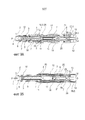
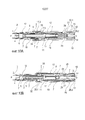
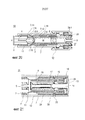
Согласно изобретению автоинъектор для введения дозы жидкого лекарственного вещества содержит:According to the invention, an autoinjector for administering a dose of a liquid drug substance comprises:
- трубчатую раму, телескопически перемещаемую в трубчатом корпусе,- a tubular frame telescopically movable in a tubular body,
- подузел носителя, содержащий трубчатый носитель, установленный с возможностью скольжения относительно рамы внутри корпуса, при этом носитель выполнен с возможностью содержать шприц с полой инъекционной иглой, приводную пружину, а также плунжер для передачи нагрузки приводной пружины на ограничитель шприца, при этом шприц выполнен с возможностью блокирования для совместного аксиального поступательного перемещения с носителем,- a carrier subassembly comprising a tubular carrier mounted to slide relative to the frame inside the housing, the carrier being configured to comprise a syringe with a hollow injection needle, a drive spring, and a plunger for transferring the load of the drive spring to the syringe stopper, the syringe being made with the ability to block for joint axial translational movement with the carrier,
- пусковую кнопку, расположенную дистально или латерально в или на корпусе,- a trigger button located distally or laterally in or on the housing,
- регулировочную пружину, расположенную вокруг носителя,- an adjustment spring located around the carrier,
- механизм регулирования протяженности иглы для соединения проксимального конца регулировочной пружины либо с носителем для его продвижения с целью выдвижения иглы, либо с рамой для отведения иглы назад, в зависимости от относительного осевого положения носителя и рамы,- a mechanism for regulating the length of the needle to connect the proximal end of the adjustment spring or with the carrier for its advancement in order to extend the needle, or with a frame to retract the needle back, depending on the relative axial position of the carrier and frame,
- механизм разблокирования плунжера, выполненный с возможностью разблокирования плунжера, когда носитель, по меньшей мере, почти достиг выдвинутого проксимального положения,- a plunger unlocking mechanism configured to unlock the plunger when the carrier has at least almost reached the extended proximal position,
- фиксирующий механизм, выполненный с возможностью соединения рамы с носителем для совместного аксиального поступательного перемещения относительно корпуса, при этом фиксирующий механизм выполнен с возможностью отсоединения рамы от носителя при приведении в действие пусковой кнопки, позволяя тем самым носителю перемещаться относительно рамы, так чтобы заставить механизм регулирования протяженности иглы переключить проксимальный конец регулировочной пружины на носитель для выдвижения иглы,- a locking mechanism configured to connect the frame with the carrier for joint axial translational movement relative to the housing, while the locking mechanism is configured to disconnect the frame from the carrier when the trigger is actuated, thereby allowing the carrier to move relative to the frame, so as to make the control mechanism the length of the needle, switch the proximal end of the adjustment spring to the carrier to extend the needle,
- механизм регулирования отведения шприца назад, выполненный с возможностью соединения дистального конца регулировочной пружины либо с носителем для отведения иглы назад, либо с корпусом.- a mechanism for controlling the withdrawal of the syringe back, made with the possibility of connecting the distal end of the adjustment spring either with the carrier for retracting the needle back, or with the body.
Подузел носителя с встроенной приводной пружиной предусматривает использование мощной приводной пружины без какой-либо ударной нагрузки на пользователя при срабатывании автоинъектора или в ходе выдвижения иглы, поскольку эти действия достигаются или им оказывается противодействие с помощью регулировочной пружины, которая может быть задана значительно более слабой, чем приводная пружина. Это позволяет доставлять лекарственные вещества, обладающие высокой вязкостью.The media subassembly with an integrated drive spring provides for the use of a powerful drive spring without any shock load on the user when the auto-injector is triggered or during the extension of the needle, because these actions are achieved or they are counteracted by an adjustment spring, which can be set much weaker than drive spring. This allows the delivery of highly viscous drugs.
Таким образом, имеется ряд существенных преимуществ в разделении функций между приводной пружиной и регулировочной пружиной. Игла автоинъектора никогда не представляет опасности, т.е. игла может быть отведена назад до завершения инъекции. Надежность автоинъектора повышена, поскольку компоненты, предназначенные для выдвижения и отведения назад иглы, не испытывают высоких ударных нагрузок со стороны мощной приводной пружины при ее свободном раздвижении. Автоинъектор вполне подходит для того, чтобы служить платформой, поскольку приводную пружину можно заменить для доставки препаратов, обладающих различной вязкостью, не нарушая функции введения или отведения назад. Это в особенности предпочтительно для текучих сред, обладающих высокой вязкостью.Thus, there are a number of significant advantages in the separation of functions between the drive spring and the adjustment spring. The autoinjector needle is never dangerous, i.e. the needle can be pulled back to complete the injection. The reliability of the auto-injector is increased, since the components designed to extend and retract the needles do not experience high shock loads from the side of the powerful drive spring when it is freely extended. The autoinjector is quite suitable to serve as a platform, since the drive spring can be replaced for the delivery of drugs with different viscosities without disturbing the function of introducing or retracting. This is particularly preferred for high viscosity fluids.
Разблокирование приводной пружины при достижении иглы выдвинутого проксимального положения, например, когда игла выдвинута на соответствующую глубину инъекции, позволяет избежать так называемой «влажной» инъекции (wet injection), т.е. утечки лекарственного вещества из иглы, что является проблемой в традиционных автоинъекторах, в которых и выдвижение иглы, и введение инъекции выполняется путем нажатия на ограничитель. Автоинъектор согласно изобретению решает проблему «влажной» инъекции путем использования отдельных пружин для поступательного перемещения носителя и для доставки препарата.Unlocking the drive spring when the needle reaches the extended proximal position, for example, when the needle is extended to the appropriate depth of injection, avoids the so-called wet injection, i.e. leakage of the drug from the needle, which is a problem in traditional autoinjectors, in which both the extension of the needle and the injection are performed by pressing the stopper. The autoinjector according to the invention solves the problem of “wet” injection by using separate springs for translational movement of the carrier and for drug delivery.
Автоинъектор согласно изобретению имеет в особенности малое количество деталей по сравнению с большинством традиционных автоинъекторов, что снижает производственные затраты. Схема с отдельной регулировочной пружиной и приводной пружиной для инъецирования текучих сред позволяет использовать одну конструкцию для жидкостей, обладающих различной вязкостью, путем простой замены приводной пружины, а также для различных объемов путем простого изменения длины плунжера. Это создает преимущество над традиционными конструкциями, в которых главная пружина также обеспечивает энергию для выдвижения и/или отведения назад иглы.The auto-injector according to the invention has a particularly small number of parts compared to most conventional auto-injectors, which reduces production costs. The circuit with a separate adjusting spring and a drive spring for injecting fluids allows the use of one design for liquids with different viscosities by simply replacing the drive spring, as well as for different volumes by simply changing the length of the plunger. This provides an advantage over traditional designs in which the main spring also provides energy for extending and / or retracting the needle.
В контексте настоящего описания рама, в общем, считается зафиксированной на месте, так что движение других компонентов описывается относительно рамы.In the context of the present description, the frame is generally considered to be locked in place, so that the movement of the other components is described relative to the frame.
В исходном состоянии автоинъектора, соответствующем состоянию поставки, проксимальный конец регулировочной пружины соединен с рамой с помощью механизма регулирования протяженности иглы, в то время как дистальный конец соединен с корпусом с помощью механизма регулирования отведения шприца назад, при этом разблокирование приводной пружины не допускается с помощью механизма разблокирования плунжера, а отсоединение рамы от носителя не допускается фиксирующим механизмом.In the initial state of the auto-injector, which corresponds to the delivery state, the proximal end of the adjustment spring is connected to the frame using a needle length adjustment mechanism, while the distal end is connected to the body using the mechanism for adjusting the syringe retraction back, while the drive spring is not allowed to be unlocked using the mechanism unlocking the plunger, and detaching the frame from the carrier is not allowed by the locking mechanism.
Для срабатывания автоинъектора корпус должен поступательно переместиться в проксимальном направлении относительно рамы, преодолевая силу регулировочной пружины. Когда корпус, по меньшей мере, почти достиг выдвинутого проксимального положения, фиксирующий механизм деблокируется, тем самым позволяя носителю совершить поступательное перемещение относительно рамы. Предпочтительно это положение достигается, когда корпус переместился на 85%-98% своего полного проксимального продвижения. Относительное поступательное перемещение корпуса и рамы может достигаться, например, путем закрепления рамы и перемещения корпуса. С целью выполнения инъекции рама, например, может быть зафиксирована путем поджатия к участку инъекции, например, коже пациента. Следовательно, пользователь, например пациент или лицо, осуществляющее уход, может захватить корпус всей кистью руки и придавить раму, выступающую из проксимального конца, к участку инъекции, тем самым поступательно перемещая корпус относительно рамы в проксимальном направлении и приводя в действие автоинъектор вышеописанным способом.For the auto-injector to fire, the housing must move forward in the proximal direction relative to the frame, overcoming the force of the adjustment spring. When the body has at least nearly reached the extended proximal position, the locking mechanism is released, thereby allowing the carrier to translate relative to the frame. Preferably, this position is achieved when the body has moved 85% -98% of its full proximal advancement. Relative translational movement of the housing and the frame can be achieved, for example, by securing the frame and moving the housing. For the purpose of injection, the frame, for example, can be fixed by pressing against the injection site, for example, the skin of the patient. Therefore, a user, such as a patient or caregiver, can grab the body with the entire hand and push the frame protruding from the proximal end to the injection site, thereby translationally moving the body relative to the frame in the proximal direction and actuating the auto-injector in the manner described above.
Носитель теперь разблокирован для поступательного перемещения в проксимальном направлении. Когда носитель поступательно перемещается в проксимальном направлении относительно корпуса и рамы, он этим переключает механизм регулирования протяженности иглы в зависимости от относительного положения носителя в раме, так чтобы отсоединить проксимальный конец регулировочной пружины от рамы и соединить его с носителем, тем самым деблокируя регулировочную пружину с целью продвижения носителя для выдвижения иглы. С целью выполнения инъекции пользователь, например, может вручную нажать пусковую кнопку, соединенную с носителем, заставляя носитель перемещаться в проксимальном направлении. Это приведет к выдвижению иглы согласно механизму регулирования протяженности иглы, описанному ранее. Опять же с целью проведения инъекции пользователь, поджимая инъектор к участку инъекции, может нажать пусковую кнопку, тем самым поступательно перемещая носитель в проксимальном направлении относительно корпуса и рамы, что приводит к переключению механизма регулирования протяженности иглы, как описано ранее.The carrier is now unlocked for translational movement in the proximal direction. When the carrier translationally moves in the proximal direction relative to the body and frame, it thereby switches the mechanism for adjusting the length of the needle depending on the relative position of the carrier in the frame, so as to disconnect the proximal end of the adjustment spring from the frame and connect it to the carrier, thereby unlocking the adjustment spring for the purpose advancing the carrier to extend the needle. In order to perform an injection, a user, for example, can manually press a start button connected to the carrier, causing the carrier to move in the proximal direction. This will lead to the extension of the needle according to the mechanism for regulating the length of the needle described earlier. Again, for the purpose of an injection, the user, pressing the injector towards the injection site, can press the start button, thereby translationally moving the carrier in the proximal direction relative to the body and frame, which leads to switching the mechanism for regulating the length of the needle, as described previously.
Продвижение носителя под действием регулировочной пружины далее приводит к продвижению иглы в кожу.The advancement of the wearer under the action of the adjustment spring further leads to the advancement of the needle into the skin.
По альтернативному варианту регулировочная пружина может быть первоначально соединена с носителем с помощью механизма регулирования протяженности иглы, так чтобы носитель немедленно продвинулся, когда фиксирующий механизм деблокируется путем поступательного перемещения корпуса в выдвинутое положение.Alternatively, the adjustment spring may be initially connected to the carrier using a needle extension mechanism so that the carrier immediately moves when the locking mechanism is released by translationally moving the housing to the extended position.
Когда игла поступательно перемещается вместе с подузлом носителя в выдвинутое проксимальное положение, в котором игла уже более небезопасна, приводная пружина деблокируется с помощью механизма разблокирования плунжера, тем самым позволяя приводной пружине продвинуть плунжер и ограничитель, по меньшей мере, для частичного выведения лекарственного вещества. Это разблокирование приводной пружины предпочтительно срабатывает при достижении носителем заданного относительного положения в пределах корпуса. Это положение достигается, когда носитель, по меньшей мере, почти достиг выдвинутого проксимального положения. Предпочтительно это положение соответствует 85%-98% проксимального выдвижения. Если, например, длина выдвижения составляет 1 см, это положение окажется в диапазоне 8,5 мм-9,8 мм длины проксимального выдвижения.When the needle moves progressively with the carrier subassembly to the extended proximal position, in which the needle is already more unsafe, the drive spring is unlocked by the plunger unlocking mechanism, thereby allowing the drive spring to advance the plunger and stopper, at least to partially withdraw the drug substance. This release of the drive spring is preferably triggered when the carrier reaches a predetermined relative position within the housing. This position is achieved when the carrier has at least almost reached the extended proximal position. Preferably, this position corresponds to 85% -98% of the proximal extension. If, for example, the extension length is 1 cm, this position will be in the range of 8.5 mm-9.8 mm of the proximal extension length.
С целью выполнения инъекции выдвинутое проксимальное положение может соответствовать намеченной глубине инъекции. Следовательно, приводная пружина может деблокироваться с помощью механизма разблокирования плунжера, когда глубина инъекции по существу достигнута, тем самым позволяя приводной пружине продвинуть плунжер и ограничитель, по меньшей мере, для частичного выведения лекарственного вещества.In order to complete the injection, the extended proximal position may correspond to the intended depth of injection. Therefore, the drive spring can be released by the plunger unlocking mechanism when the depth of injection is substantially reached, thereby allowing the drive spring to advance the plunger and limiter, at least to partially withdraw the drug substance.
Когда автоинъектор удаляется с участка инъекции после того как ограничитель коснулся дна в шприце или в любой момент в процессе инъекции, корпус поступательно перемещается в дистальном направлении под воздействием регулировочной пружины относительно подузла носителя.When the auto-injector is removed from the injection site after the stopper has touched the bottom in the syringe or at any time during the injection, the casing translationally moves in the distal direction under the influence of the adjustment spring relative to the carrier subassembly.
Отведение иглы назад запускается путем перемещения корпуса в дистальном направлении относительно рамы и носителя под силовым воздействием регулировочной пружины. Когда корпус достигает определенного положения относительно носителя, проксимальный конец регулировочной пружины отсоединяется от носителя и соединяется с рамой с помощью механизма регулирования протяженности иглы. Кроме того, дистальный конец регулировочной пружины отсоединяется от пусковой муфты и соединяется с носителем с помощью механизма регулирования отведения шприца назад. Последовательность данного переключения принципиально важна, поскольку отведение назад не произойдет, если обе втулки крепятся к носителю одновременно. Эта проблема решается с помощью разделения переключения втулок путем существенного перемещения корпуса, что предусматривает, например, сначала включение механизма регулирования протяженности иглы, а затем механизма регулирования отведения шприца назад.Lead back of the needle is started by moving the housing in the distal direction relative to the frame and the carrier under the force of the adjusting spring. When the housing reaches a certain position relative to the carrier, the proximal end of the adjustment spring is disconnected from the carrier and connected to the frame using a needle extension control mechanism. In addition, the distal end of the adjustment spring is disconnected from the start-up clutch and connected to the carrier using the mechanism for controlling the withdrawal of the syringe back. The sequence of this switch is fundamentally important, since a retraction will not occur if both bushes are attached to the carrier at the same time. This problem is solved by separating the switching of the bushings by significantly moving the housing, which involves, for example, first turning on the mechanism for regulating the length of the needle, and then the mechanism for regulating the removal of the syringe back.
Поскольку регулировочная пружина теперь поджимается к раме в проксимальном направлении и к носителю в дистальном направлении, подузел носителя отводится назад в раму в безопасное положение иглы с помощью регулировочной пружины, где проксимальный конец иглы накрыт. Поскольку это отведение назад запускается относительным положением между корпусом, рамой и носителем, оно, в частности, не зависит от выведения лекарственного вещества. С целью выполнения инъекции данное положение корпуса относительно носителя может достигаться, например, если автоинъектор удаляется с участка инъекции. Когда, например, пользователь, по-прежнему захватывающий корпус всей кистью руки и поджимающий раму, выступающую из проксимального конца, к участку инъекции, перемещает руку в дистальном направлении, корпус перемещается в дистальном направлении относительно носителя и рамы, при этом механизм срабатывает, как описано ранее. Игла, таким образом, отводится назад с участка инъекции под силовым воздействием регулировочной пружины.Since the adjusting spring is now pressed against the frame in the proximal direction and the carrier in the distal direction, the carrier subassembly is retracted back into the frame to the safe needle position using the adjustment spring, where the proximal end of the needle is covered. Since this retraction is triggered by the relative position between the body, frame and carrier, it is, in particular, independent of the withdrawal of the drug substance. For the purpose of injection, this position of the housing relative to the carrier can be achieved, for example, if the autoinjector is removed from the injection site. When, for example, the user, still gripping the body with the whole hand and pressing the frame protruding from the proximal end to the injection site, moves the hand in the distal direction, the body moves in the distal direction relative to the carrier and the frame, and the mechanism operates as described earlier. The needle is thus retracted back from the injection site under the force of the adjusting spring.
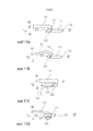
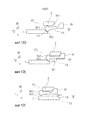
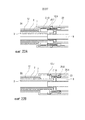
Согласно одному варианту осуществления механизм регулирования протяженности иглы может содержать первую втулку, смещаемую с помощью регулировочной пружины в проксимальном направлении, при этом на первой втулке проксимально расположена, по меньшей мере, одна упругая балка, при этом на носителе и корпусе расположены соответствующие выемки, причем поперечная протяженность головки упругой балки превышает зазор между носителем и рамой, что заставляет головку упругой балки упираться в дистальную поверхность в выемке в раме, не допуская при этом отклонения во внутреннем направлении носителем, или упираться в дистальную поверхность в выемке в носителе, не допуская при этом отклонения в наружном направлении рамой, тем самым передавая нагрузку от регулировочной пружины на носитель для выдвижения иглы, при этом упругая балка выполнена с возможностью переключения между рамой и носителем с помощью наклонного зацепления головки с дистальными поверхностями под нагрузкой регулировочной пружины в зависимости от относительного продольного положения между рамой и носителем. Поскольку головка упругой балки может образовывать наклон во внутреннем и наружном направлении, ее можно назвать «стреловидным наконечником».According to one embodiment, the mechanism for adjusting the length of the needle may comprise a first sleeve that can be displaced by the adjustment spring in the proximal direction, with at least one elastic beam being proximally located on the first sleeve, with corresponding recesses being provided on the carrier and body, the length of the head of the elastic beam exceeds the gap between the carrier and the frame, which causes the head of the elastic beam to abut against the distal surface in the recess in the frame, preventing this deviation in the internal direction of the carrier, or abut against the distal surface in the recess in the carrier, while not allowing deviations in the outer direction of the frame, thereby transferring the load from the adjustment spring to the carrier to extend the needle, while the elastic beam is made with the ability to switch between the frame and the carrier by inclined engagement of the head with distal surfaces under the load of the adjustment spring, depending on the relative longitudinal position between the frame and the carrier. Since the head of the elastic beam can form a slope in the inner and outer directions, it can be called a “swept tip”.
Механизм разблокирования плунжера может содержать, по меньшей мере, один упругий рычаг на носителе, выполненный с возможностью наклонного зацепления с плунжером, так чтобы их расцеплять под нагрузкой приводной пружины, при этом от дистальной торцевой поверхности пусковой кнопки в проксимальном направлении выступает штырь, так чтобы поддерживать упругий рычаг, не допуская отцепления носителя от плунжера, а значит, разблокирования приводной пружины, когда носитель находится в дистальном положении. Пусковая кнопка выполнена с возможностью сохранять свое положение относительно корпуса, когда носитель поступательно перемещается для продвижения иглы. Это означает, что пусковая кнопка, первоначально соединенная с носителем, при нажатии проталкивает носитель в проксимальном направлении. Как только регулировочная пружина принимает на себя дальнейшее продвижение носителя, пусковая кнопка может упираться в корпус и отсоединяться от носителя, оставаясь в своем положении при перемещении носителя. Следовательно, упругий рычаг отделяется от штыря, тем самым обеспечивая изгиб упругого рычага благодаря наклонному зацеплению под нагрузкой приводной пружины для отцепления плунжера от носителя и разблокирования приводной пружины для доставки препарата, когда носитель достиг заданного положения в процессе продвижения иглы.The plunger unlocking mechanism may include at least one resilient lever on the carrier configured to obliquely engage the plunger so that they disengage under the load of the drive spring, while a pin protrudes from the distal end surface of the start button in the proximal direction so as to support elastic lever, preventing the carrier from detaching from the plunger, and therefore, unlocking the drive spring when the carrier is in a distal position. The start button is configured to maintain its position relative to the body when the carrier is translationally moved to advance the needle. This means that the release button, initially connected to the media, pushes the media in the proximal direction when pressed. As soon as the adjustment spring takes on further advancement of the carrier, the start button can abut against the housing and detach from the carrier, remaining in its position when moving the carrier. Therefore, the elastic lever is separated from the pin, thereby bending the elastic lever due to inclined engagement under load of the drive spring to disengage the plunger from the carrier and unlock the drive spring for drug delivery when the carrier has reached a predetermined position during needle advancement.
Фиксирующий механизм может быть выполнен с возможностью обеспечения силы сопротивления, которую требуется преодолеть для продвижения носителя в проксимальном направлении с целью выдвижения иглы. Носитель может быть соединен с пусковой кнопкой, при этом усилие для проталкивания пусковой кнопкой должно превышать силу сопротивления фиксирующего механизма. Например, когда пользователь прикладывает силу к пусковой кнопке, превышающую заданную величину, фиксирующий механизм деблокируется, инициируя цикл инъекции. Если заданная величина не превышена, фиксирующий механизм проталкивает носитель и пусковую кнопку обратно в их предшествующее положение.The locking mechanism may be configured to provide a drag force that needs to be overcome in order to advance the carrier in the proximal direction to extend the needle. The carrier can be connected to the start button, while the force for pushing the start button must exceed the resistance force of the locking mechanism. For example, when the user applies a force to the start button that exceeds a predetermined value, the locking mechanism is released, initiating an injection cycle. If the set value is not exceeded, the locking mechanism pushes the carrier and the start button back to their previous position.
Это гарантирует, что автоинъектор всегда находится в определенном состоянии, либо приведенным в действие, либо не приведенным в действие, а не задействованным наполовину в силу нерешительности пользователя.This ensures that the auto-injector is always in a certain state, either powered up or not powered, and not half used due to the user's indecision.
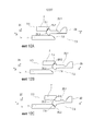
Фиксирующий механизм может быть также выполнен с возможностью обеспечения силы сопротивления, противодействующей поступательному перемещению носителя в дистальном направлении относительно рамы для удерживания носителя в определенном положении в переходном состоянии, когда оба конца регулировочной пружины отсоединены от носителя. Это переходное состояние может потребоваться для отведения иглы назад при удалении с участка инъекции. Когда носитель смещен к участку инъекции с помощью регулировочной пружины, перед удалением с участка инъекции его требуется отсоединить от проксимального конца регулировочной пружины и соединить с дистальным концом для отведения назад. Последовательность данного переключения принципиально важна, поскольку отведение назад не произойдет, если оба конца регулировочной пружины крепятся к носителю одновременно. Эта проблема решается с помощью разделения переключения концов путем существенного перемещения корпуса, который перемещается в дистальном направлении относительно рамы при удалении с участка инъекции под силовым воздействием регулировочной пружины. Поскольку подключение дистального конца регулировочной пружины к носителю зависит от относительного положения корпуса по отношению к носителю, носитель должен быть зафиксирован в переходном состоянии, что достигается с помощью фиксирующего механизма.The locking mechanism may also be configured to provide a resistance force counteracting the translational movement of the carrier in the distal direction relative to the frame to hold the carrier in a certain position in a transition state when both ends of the adjustment spring are disconnected from the carrier. This transient state may be required to retract the needle when removed from the injection site. When the carrier is biased towards the injection site using the adjustment spring, it must be disconnected from the proximal end of the adjustment spring and connected to the distal end to retract before being removed from the injection site. The sequence of this switch is fundamentally important, since a retraction will not occur if both ends of the adjustment spring are attached to the carrier at the same time. This problem is solved by separating the switching ends by significantly moving the housing, which moves in the distal direction relative to the frame when removed from the injection site under the force of the adjusting spring. Since the connection of the distal end of the adjustment spring to the carrier depends on the relative position of the housing relative to the carrier, the carrier must be fixed in a transition state, which is achieved using a locking mechanism.
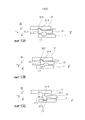
В одном варианте осуществления фиксирующий механизм содержит упругую балку на раме, а также ромбовидное наклонное звено на носителе, при этом упругая балка по существу является прямолинейной в релаксированном состоянии, причем первая головка балки выполнена с возможностью взаимодействия в наклонном зацеплении с проксимальной четвертой наклонной плоскостью или дистальной пятой наклонной плоскостью на ромбовидном наклонном звене так, что приложение перемещающего усилия к носителю относительно рамы в проксимальном направлении, когда первая головка балки введена в зацепление с четвертой наклонной плоскостью, изгибает упругую балку в одном поперечном направлении, например, наружу, когда превышена заданная величина перемещающего усилия, по меньшей мере, зависящего от сопротивления упругой балки, так чтобы позволить первой головке балки совершить перемещение вдоль одной поперечной стороны ромбовидного наклонного звена при непрерывном относительном поступательном перемещении компонентов. Головка балки может выступать в поперечном направлении от упругой балки, так чтобы деформировать упругую балку по механизму рычага при поджатии к ромбовидному наклонному звену, тем самым также определяя заданную величину перемещающего усилия, которую носитель должен преодолеть. Кроме того, соприкасающиеся поверхности первой головки балки и ромбовидного наклонного звена могут обладать коэффициентом трения, приспособленным для определения требуемого усилия путем соответствующего подбора их формы и характеристик материала. Упругая балка имеет возможность срелаксировать, когда первая головка балки достигает пятой наклонной плоскости, тем самым входя в зацепление с ней так, что приложение перемещающего усилия к носителю в дистальном направлении изгибает упругую балку в другом поперечном направлении, например, внутрь, когда превышена заданная величина перемещающего усилия, по меньшей мере, зависящего от сопротивления упругой балки, так чтобы позволить первой головке балки совершить перемещение вдоль другой поперечной стороны ромбовидного наклонного звена при непрерывном поступательном перемещении носителя. Первая головка балки может также релаксировать за четвертой наклонной плоскостью в конце этого перемещения, чтобы не допустить повторного продвижения носителя, например при сильном встряхивании автоинъектора после использования.In one embodiment, the locking mechanism comprises an elastic beam on the frame, as well as a diamond-shaped inclined link on the carrier, the elastic beam being essentially straight in the relaxed state, the first beam head being configured to interact in inclined engagement with the proximal fourth inclined plane or distal the fifth inclined plane on the rhomboid inclined link so that the application of a moving force to the carrier relative to the frame in the proximal direction when the first beam head is engaged with the fourth inclined plane, bends the elastic beam in one transverse direction, for example, to the outside, when the predetermined amount of displacement force, at least depending on the resistance of the elastic beam, is exceeded so as to allow the first beam head to move along one the transverse side of the diamond-shaped inclined link with continuous relative translational movement of the components. The beam head can protrude in the transverse direction from the elastic beam, so as to deform the elastic beam according to the lever mechanism when it is pressed against the diamond-shaped inclined link, thereby also determining a predetermined amount of displacement force that the carrier must overcome. In addition, the contacting surfaces of the first beam head and the diamond-shaped inclined link may have a friction coefficient adapted to determine the required force by appropriate selection of their shape and material characteristics. The elastic beam has the ability to relax when the first beam head reaches the fifth inclined plane, thereby entering into engagement with it so that the application of a displacing force to the carrier in the distal direction bends the elastic beam in another transverse direction, for example, inward, when the specified value of the displacement forces at least dependent on the resistance of the elastic beam so as to allow the first beam head to move along the other transverse side of the diamond-shaped inclined link with continuous translational movement of the carrier. The first beam head can also relax beyond the fourth inclined plane at the end of this movement, in order to prevent the carrier from moving again, for example, with strong shaking of the auto-injector after use.
Совершенно очевидно, что положения упругой балки на раме и ромбовидного наклонного звена на носителе могут переключаться без изменения функции фиксирующего механизма.It is quite obvious that the positions of the elastic beam on the frame and the diamond-shaped inclined link on the carrier can be switched without changing the function of the locking mechanism.
При сборке автоинъектора или шприца к игле может крепиться защитный кожух иглы для сохранения стерильности иглы, а также недопущения повреждения иглы в процессе сборки и доступа к игле со стороны пользователя во избежание укола пальца. Снятие защитного кожуха иглы перед проведением инъекции обычно требует приложения относительно большого усилия для стягивания защитного кожуха иглы с иглы и снятия канюли в проксимальном направлении. Чтобы сохранить безопасность иглы в прединъекционный период и не допустить обнажения иглы, поступательного перемещения шприца в проксимальном направлении, вызванного этим усилием, требуется избежать. С этой целью корпус может быть выполнен с возможностью блокирования фиксирующего механизма перед поступательным перемещением в проксимальном направлении относительно рамы, когда рама поджимается к участку инъекции, так чтобы избежать поступательного перемещения носителя. Это может достигаться с помощью ребра в корпусе, не допускающего изгиба упругой балки фиксирующего механизма путем поддержки его в наружном направлении. Поступательное перемещение корпуса в выдвинутое положение в проксимальном направлении при контакте с участком инъекции приспособлено для разблокирования фиксирующего механизма, приводя его в рабочее состояние. Это может достигаться с помощью ребра, перемещаемого вместе с корпусом, так чтобы более не поддерживать в наружном направлении упругую балку фиксирующего механизма. Для обеспечения того, чтобы корпус не перемещался в проксимальном направлении, деблокируя фиксирующий механизм перед снятием защитного кожуха иглы, к проксимальному концу корпуса может крепиться колпачок, так чтобы не допустить доступа к раме перед снятием колпачка. Колпачок предпочтительно входит в зацепление с защитным кожухом иглы посредством зубца, так чтобы снять защитный кожух иглы при стягивании колпачка с автоинъектора. Чтобы способствовать снятию колпачка, он может иметь профильную поверхность, сопряженную с поверхностью на корпусе, так чтобы колпачок снимался при вращении. Зубец может соединяться с колпачком так, чтобы позволить им вращаться независимо, чтобы избежать передачи крутящего момента на защитный кожух иглы при вращении колпачка с целью недопущения деформирования иглы внутри защитного кожуха иглы.When assembling an auto-injector or syringe, a needle protective cover can be attached to the needle to maintain the sterility of the needle, as well as to prevent damage to the needle during assembly and access to the needle by the user to avoid finger pricking. Removing the needle shield from the injection usually requires a relatively large amount of force to pull the needle shield from the needle and removing the cannula in the proximal direction. In order to maintain the safety of the needle in the pre-injection period and to prevent exposure of the needle, the translational movement of the syringe in the proximal direction caused by this force must be avoided. To this end, the housing can be configured to lock the locking mechanism before translational movement in the proximal direction relative to the frame, when the frame is pressed against the injection site, so as to avoid translational movement of the carrier. This can be achieved by means of a rib in the housing that does not allow the elastic beam of the locking mechanism to bend by supporting it in the outward direction. The translational movement of the housing in an extended position in the proximal direction upon contact with the injection site is adapted to unlock the locking mechanism, bringing it into working condition. This can be achieved by means of a rib that is moved together with the housing so that it no longer supports the elastic beam of the locking mechanism in the outward direction. To ensure that the body does not move in the proximal direction by releasing the locking mechanism before removing the needle shield, a cap can be attached to the proximal end of the body so as to prevent access to the frame before removing the cap. The cap is preferably engaged with the needle shield by means of a tooth, so as to remove the needle shield when pulling the cap from the auto-injector. To facilitate removal of the cap, it may have a profiled surface mating with a surface on the housing, so that the cap is removed during rotation. The tooth can be connected to the cap in such a way as to allow it to rotate independently, in order to avoid transmitting torque to the needle guard while rotating the cap to prevent deformation of the needle inside the needle guard.
Дистально расположенная пусковая кнопка, по меньшей мере, первоначально может соединяться с носителем, при этом корпус выполнен с возможностью упора в пусковую кнопку в исходном состоянии, не допуская нажатия пусковой кнопки. При поступательном перемещении корпуса в выдвинутое положение, когда рама поджимается к участку инъекции, пусковая кнопка остается соединенной с носителем, выступая, таким образом, из корпуса, перемещенного относительно рамы, носителя и пусковой кнопки, так чтобы позволить нажать пусковую кнопку для запуска цикла инъекции. Следовательно, определена последовательно операций для задействования автоинъектора, предусматривающая сначала поджатие его к участку инъекции, а затем нажатие пусковой кнопки. Это позволяет снизить риск ранения пальца иглой, особенно если пользователь находится в замешательстве по поводу того, какой конец автоинъектора следует приложить к коже. Без обеспечения такой последовательности пользователь рискует ввести иглу в большой палец, что гораздо менее вероятно, если последовательность принудительно установлена.The distally located start button, at least initially, can be connected to the carrier, while the housing is configured to abut the start button in its initial state, without allowing the start button to be pressed. When the housing is moved to the extended position, when the frame is pressed against the injection site, the start button remains connected to the carrier, thus protruding from the body moved relative to the frame, the carrier and the start button, so that the start button can be pressed to start the injection cycle. Therefore, the sequence of operations for activating the auto-injector is determined, providing for first pressing it to the injection site, and then pressing the start button. This reduces the risk of injuring a finger with a needle, especially if the user is confused about which end of the autoinjector should be applied to the skin. Without this sequence, the user risks inserting the needle into the thumb, which is much less likely if the sequence is forcibly established.
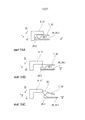
Механизм регулирования отведения шприца назад может содержать вторую втулку, плотно прилегающую к дистальному концу регулировочной пружины и имеющую упругую проксимальную балку, которая имеет вторую головку балки, обладающую внутренним выступом. Вторая головка балки выполнена с возможностью пребывать в наклонном зацеплении со вторым фиксатором корпуса в корпусе, создавая наклон второй головки балки во внутреннем направлении под силовым воздействием регулировочной пружины в дистальном направлении. Внутренний выступ выполнен с возможностью упора во внутреннем направлении в носитель, чтобы не допустить внутреннего отклонения второй головки балки и поддерживать вторую втулку закрепленной на корпусе. На носителе расположена третья выемка, чтобы позволить внутреннему выступу изогнуться во внутреннем направлении при поступательном перемещении корпуса в дистальном направлении относительно носителя при удалении автоинъектора с участка инъекции.The mechanism for controlling the withdrawal of the syringe back may include a second sleeve that fits snugly against the distal end of the adjustment spring and has an elastic proximal beam, which has a second beam head with an internal protrusion. The second beam head is configured to remain in inclined engagement with the second housing retainer in the housing, creating a tilt of the second beam head in the inner direction under the force of the adjusting spring in the distal direction. The inner protrusion is made with the possibility of abutment in the inner direction in the carrier to prevent internal deviation of the second beam head and to support the second sleeve mounted on the housing. A third recess is located on the carrier to allow the inner protrusion to bend inward while translating the housing in a distal direction relative to the carrier while removing the auto-injector from the injection site.
В альтернативном варианте осуществления первая втулка и/или вторая втулка могут также соединяться по резьбе с одним из компонентов, который они должны соединять с регулировочной пружиной, при этом корпус должен быть выполнен с возможностью недопущения отсоединения резьб в некоторых относительных продольных положениях, позволяя при этом втулке вращаться с выходом из резьбового зацепления в других относительных продольных положениях, чтобы позволить втулкам переключиться на соответствующий другой компонент, который требуется соединить с регулировочной пружиной.In an alternative embodiment, the first sleeve and / or second sleeve may also be threaded to one of the components that they must be connected to the adjustment spring, the housing being configured to prevent the threads from detaching in some relative longitudinal positions, while allowing the sleeve to rotate out of threaded engagement in other relative longitudinal positions to allow the bushings to switch to the corresponding other component that needs to be connected with an adjustment spring.
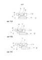
В альтернативном варианте осуществления пусковая кнопка может быть расположена дистально, при этом корпус выполнен в виде накладного муфтового пускового механизма, закрытая дистальная торцевая поверхность которого накрывает пусковую кнопку. В исходном состоянии между дистальной торцевой поверхностью муфтового пускового механизма и пусковой кнопкой предусмотрен зазор, допускающий некоторое перемещение муфтового пускового механизма в противодействие регулировочной пружине в проксимальном направлении на первом этапе перед упором в пусковую кнопку. Как только муфтовый пусковой механизм соприкоснулся с пусковой кнопкой, пусковая кнопка проталкивается муфтовым пусковым механизмом для дальнейшего поступательного перемещения на втором этапе. Данный вариант осуществления предусматривает сохранение большинства компонентов автоинъектора, при этом только описанные элементы требуют модификации, позволяющей адаптировать платформенное устройство к определенным требованиям. Автоинъектор, имеющий муфтовый пусковой механизм, в особенности пригоден для людей, не обладающих достаточными двигательными возможностями, поскольку в отличие от традиционных автоинъекторов приведение в действие не требует управления малыми кнопками отдельными пальцами. Вместо этого используется полностью кисть руки.In an alternative embodiment, the trigger button may be located distally, while the housing is made in the form of a patch clutch trigger mechanism, the closed distal end surface of which covers the trigger button. In the initial state, a gap is provided between the distal end surface of the clutch trigger and the trigger button, allowing some movement of the coupling trigger mechanism in opposition to the adjustment spring in the proximal direction at the first stage before stopping the trigger button. As soon as the clutch trigger comes into contact with the trigger, the trigger is pushed by the coupling trigger for further translational movement in the second stage. This embodiment provides for the preservation of most components of the auto-injector, while only the described elements require modification that allows you to adapt the platform device to certain requirements. An autoinjector having a clutch trigger is particularly suitable for people who do not have sufficient motor capabilities, because unlike traditional autoinjectors, actuation does not require the control of small buttons with individual fingers. Instead, the entire hand is used.
Отведение назад иглы требует от пользователя приподнять автоинъектор на достаточное расстояние с участка инъекции, чтобы позволить корпусу или муфтовому пусковому механизму поступательно переместиться обратно в дистальном направлении для переключения регулировочной пружины. Поскольку пользователю бывает трудно определить, закончена инъекция или нет, может быть предусмотрен деблокируемый компонент обратной связи, способный при разблокировании генерировать слышимый или тактильный сигнал обратной связи для пользователя, при этом компонент обратной связи выполнен с возможностью разблокирования, когда плунжер достигает некоторого положения относительно шприца, в котором ограничитель расположен вблизи проксимального конца шприца, т.е., например, когда инъекция, по меньшей мере, почти закончена. Разблокированный компонент обратной связи далее соударяется с компонентом корпуса, таким как корпус, муфтовый пусковой механизм или пусковая кнопка, указывая на окончание инъекции. Соударение с непосредственно доступным компонентом позволяет хорошо воспринимать звук, а также получить прямой доступ к кисти руки или пальцам пользователя для генерирования тактильного сигнала обратной связи. Предпочтительно компонент обратной связи может совершить удар по пусковой кнопке, выполненной в виде барабана для издавания громкого звука.Retracting the needles requires the user to raise the auto-injector a sufficient distance from the injection site to allow the housing or clutch trigger to move forward backward in the distal direction to switch the adjustment spring. Since it may be difficult for the user to determine whether the injection is complete or not, a releasable feedback component may be provided which, when unlocked, can generate an audible or tactile feedback signal for the user, while the feedback component is configured to unlock when the plunger reaches a certain position relative to the syringe, in which the limiter is located near the proximal end of the syringe, i.e., for example, when the injection is at least almost complete. The unlocked feedback component then collides with the housing component, such as the housing, clutch trigger or trigger, indicating the end of the injection. Collision with a directly accessible component allows you to perceive sound well, as well as get direct access to the user's hand or fingers to generate a tactile feedback signal. Preferably, the feedback component may strike a trigger button configured as a drum for making a loud sound.
Длина выдвижения иглы или глубина предпочтительно определяется носителем относительно рамы, а не относительно корпуса, так что если рука пользователя дрогнет или не сможет удерживать автоинъектор плотно прижатым к участку инъекции, один лишь корпус переместиться в дистальном направлении, при этом глубина инъекции сохранится постоянной. Пока это перемещение корпуса не превысит установленное расстояние, корпус не переключит регулировочную пружину для отведения иглы назад.The extension length of the needle or the depth is preferably determined by the wearer relative to the frame, and not relative to the body, so if the user's hand trembles or cannot hold the auto-injector firmly pressed to the injection site, only the body will move in the distal direction, while the depth of injection will remain constant. As long as this movement of the body does not exceed the set distance, the body will not switch the adjustment spring to retract the needle.
Автоинъектором можно управлять с использованием ряда основных механических операций:Autoinjector can be controlled using a number of basic mechanical operations:
- Корпус перемещают относительно рамы, сжимая регулировочную пружину, что дает пользователю впечатление вдавливания муфты сцепления с кожей. Все остальные компоненты остаются на том же месте в ходе продвижения корпуса, что приводит к появлению пусковой кнопки на дистальном конце корпуса.- The housing is moved relative to the frame, compressing the adjustment spring, which gives the user the impression of pressing the clutch with the skin. All other components remain in the same place during the advancement of the housing, which leads to the appearance of a start button on the distal end of the housing.
- Пользователь нажимает пусковую кнопку, которой теперь можно оперировать. Нажатие кнопки непосредственно приводит в движение носитель, а значит и управляющий подузел, в проксимальном направлении на заданное расстояние, пока регулировочная пружина не будет захвачена первой втулкой и полностью выведет иглу, например, введет иглу в участок инъекции.- The user presses the start button, which can now be operated. Pressing the button directly drives the carrier, and hence the control subassembly, in the proximal direction for a predetermined distance, until the adjustment spring is gripped by the first sleeve and fully withdraws the needle, for example, introduces the needle into the injection site.
- Пусковая кнопка останавливается на дистальном конце корпуса, когда носитель продолжает поступательное перемещение в проксимальном направлении. Движение носителя относительно пусковой кнопки используется для разблокирования приводной пружины непосредственно перед достижением полной глубины, например путем выведения штыря на пусковой кнопке из носителя, что позволяет двигаться плунжеру. Приводная пружина приводит плунжер в движение по цилиндру шприца, выводя лекарственное вещество.- The start button stops at the distal end of the housing when the carrier continues to translate in the proximal direction. The movement of the carrier relative to the start button is used to unlock the drive spring immediately before reaching full depth, for example by removing the pin on the start button from the carrier, which allows the plunger to move. The drive spring drives the plunger along the syringe barrel, expelling the drug substance.
- Механизм обратной связи деблокируется, когда плунжер находится в конце своего пути, незадолго до того как ограничитель коснется дна шприца, что служит воспринимаемым на слух и/или тактильным индикатором окончания инъекции для пользователя.- The feedback mechanism is released when the plunger is at the end of its path, shortly before the limiter touches the bottom of the syringe, which serves as a listening and / or tactile indicator of the end of the injection for the user.
- Игла остается полностью выдвинутой, пока пользователь не переместит корпус назад на определенное расстояние относительно рамы, и в этот момент вторая втулка отсоединяется от корпуса и соединяется с носителем, в то время как первая втулка отсоединяется от носителя и соединяется с рамой, тем самым позволяя регулировочной пружине отвести назад носитель, а значит и иглу.- The needle remains fully extended until the user moves the case back a certain distance relative to the frame, at which point the second sleeve is disconnected from the body and connected to the carrier, while the first sleeve is disconnected from the carrier and connected to the frame, thereby allowing adjustment spring back the carrier, and therefore the needle.
Автоинъектор предпочтительно может использоваться для подкожных или внутримышечных инъекций, в частности для доставки анальгетика, антикоагулянта, инсулина, производной инсулина, гепарина, препарата Ловенокс, вакцины, гормона роста, пептидного гормона, протеина, антител и сложных углеводов. Автоинъектор предпочтительно может быть выполнен с возможностью инъецирования жидкого лекарственного вещества, обладающего высокой вязкостью, например жидких растворов препарата антитела.The autoinjector can preferably be used for subcutaneous or intramuscular injections, in particular for the delivery of an analgesic, anticoagulant, insulin, derivative of insulin, heparin, Lowenox preparation, vaccine, growth hormone, peptide hormone, protein, antibodies and complex carbohydrates. The autoinjector may preferably be configured to inject a liquid drug having a high viscosity, for example, liquid solutions of an antibody preparation.
Термин «лекарственное вещество» в настоящем описании означает фармацевтическую композицию, содержащую, по меньшей мере, одно фармацевтически активное соединение,The term “drug substance” as used herein means a pharmaceutical composition comprising at least one pharmaceutically active compound,
при этом в одном варианте осуществления фармацевтически активное соединение имеет молекулярный вес до 1500 Da и/или представляет собой пептид, протеин, полисахарид, вакцину, ДНК, РНК, антитело, энзим, гормон или олигонуклеотид либо смесь вышеупомянутых фармацевтически активных соединений,however, in one embodiment, the pharmaceutically active compound has a molecular weight of up to 1,500 Da and / or is a peptide, protein, polysaccharide, vaccine, DNA, RNA, antibody, enzyme, hormone or oligonucleotide, or a mixture of the aforementioned pharmaceutically active compounds,
при этом в следующем варианте осуществления фармацевтически активное соединение является полезным для лечения и/или профилактики сахарного диабета или осложнений, связанных с сахарным диабетом, таких как диабетическая ретинопатия, тромбоэмболийные осложнения, такие как тромбоз глубоких вен или легочная тромбоэмболия, острый коронарный синдром (ACS), ангина, инфаркт миокарда, злокачественные новообразования, дегенерация макулы, воспалительные заболевания, поллиноз, атеросклероз и/или ревматоидный артрит,in a further embodiment, the pharmaceutically active compound is useful for treating and / or preventing diabetes mellitus or complications associated with diabetes mellitus, such as diabetic retinopathy, thromboembolism complications such as deep vein thrombosis or pulmonary thromboembolism, acute coronary syndrome (ACS) , tonsillitis, myocardial infarction, malignant neoplasms, macular degeneration, inflammatory diseases, hay fever, atherosclerosis and / or rheumatoid arthritis,
при этом в следующем варианте осуществления фармацевтически активное соединение содержит, по меньшей мере, один пептид для лечения и/или профилактики сахарного диабета или осложнений, связанных с сахарным диабетом, таких как диабетическая ретинопатия,however, in the following embodiment, the pharmaceutically active compound contains at least one peptide for treating and / or preventing diabetes mellitus or complications associated with diabetes mellitus, such as diabetic retinopathy,
при этом в следующем варианте осуществления фармацевтически активное соединение содержит, по меньшей мере, один инсулин человека или аналог инсулина человека или производную, глюкагоноподобный пептид (GLP-1) либо аналог или его производную, или экседин-3, или экседин-4, либо аналог или производную экседина-3 или экседина-4.in a further embodiment, the pharmaceutically active compound comprises at least one human insulin or a human insulin analog or derivative, glucagon-like peptide (GLP-1) or an analog or derivative thereof, or exedin-3, or exedin-4, or an analogue or a derivative of exedin-3 or exedin-4.
Аналоги инсулина могут представлять собой, например, Gly(A21), Arg(B31), Arg(B32) человеческий инсулин; Lys(B3), Glu(B29) человеческий инсулин; Lys(B28), Pro(B29) человеческий инсулин; Asp(B28) человеческий инсулин; человеческий инсулин, при этом пролин в позиции B28 замещается на Asp, Lys, Leu, VaL или Ala, а в позиции B29 Lys может быть замещен на Pro; Ala(B26) человеческий инсулин; Des(B28-B30) человеческий инсулин; Des(B27) человеческий инсулин и Des(B30) человеческий инсулин.Insulin analogs can be, for example, Gly (A21), Arg (B31), Arg (B32) human insulin; Lys (B3); Glu (B29) human insulin; Lys (B28), Pro (B29) human insulin; Asp (B28) human insulin; human insulin, while the proline at position B28 is replaced by Asp, Lys, Leu, VaL or Ala, and at position B29 Lys can be replaced by Pro; Ala (B26) human insulin; Des (B28-B30) human insulin; Des (B27) human insulin and Des (B30) human insulin.
Производные инсулина могут представлять собой, например, B29-N-миристоил-дез(B30) человеческий инсулин; B29-N-палмитоил - дез(B30) человеческий инсулин; B29-N-миристоил человеческий инсулин; B29-N-палмитоил человеческий инсулин; B28-N-миристоил LysB28ProB29 человеческий инсулин; B28-N-палмитоил - LysB28ProB29 человеческий инсулин; B30-N-миристоил -ThrB29LysB30 человеческий инсулин; B30-N-палмитоил - ThrB29LysB30 человеческий инсулин; B29-N-(N-палмитоил-Y-глутамил)-дез(B30) человеческий инсулин; B29-N-(N-литохолил-Y-глутамил)-дез(B30) человеческий инсулин; B29-N-(ω-карбоксигептадеканоил)-дез(B30) человеческий инсулин и B29-N-(ω-карбоксигептадеканоил) человеческий инсулин.Derivatives of insulin can be, for example, B29-N-myristoyl des (B30) human insulin; B29-N-palmitoyl des (B30) human insulin; B29-N-myristoyl human insulin; B29-N-palmitoyl human insulin; B28-N-myristoyl LysB28ProB29 human insulin; B28-N-palmitoyl - LysB28ProB29 human insulin; B30-N-myristoyl -ThrB29LysB30 human insulin; B30-N-palmitoyl - ThrB29LysB30 human insulin; B29-N- (N-palmitoyl-Y-glutamyl) des (B30) human insulin; B29-N- (N-lithocholyl-Y-glutamyl) des (B30) human insulin; B29-N- (ω-carboxyheptadecanoyl) des (B30) human insulin; and B29-N- (ω-carboxyheptadecanoyl) human insulin.
Эксендин-4, например, означает Экседин-4(1-39), последовательность пептидов H-His-Gly-Glu-Gly-Thr-Phe-Thr-Ser-Asp-Leu-Ser-Lys-GIn-Met-Glu-Glu-Glu-Ala-Val-Arg-Leu-Phe-Ile-Glu-Trp-Leu-Lys-Asn-Gly-Gly-Pro-Ser-Ser-Gly-Ala-Pro-Pro-Pro-Ser-NH2.Exendin-4, for example, means Exedin-4 (1-39), the sequence of the peptides H-His-Gly-Glu-Gly-Thr-Phe-Thr-Ser-Asp-Leu-Ser-Lys-GIn-Met-Glu- Glu-Glu-Ala-Val-Arg-Leu-Phe-Ile-Glu-Trp-Leu-Lys-Asn-Gly-Gly-Pro-Ser-Ser-Gly-Ala-Pro-Pro-Pro-Ser-NH2.
Производные Экседина-4, например, выбираются из следующего списка соединений:Derivatives of Exedin-4, for example, are selected from the following list of compounds:
H-(Lys)4-дез Pro36, дез Pro37 Эксендин-4(1-39)-NH2,H- (Lys) 4-des Pro36, des Pro37 Exendin-4 (1-39) -NH2,
H-(Lys)5-дез Pro36, дез Pro37 Эксендин-4(1-39)-NH2, дез Pro36 [Asp28] Эксендин-4(1-39), дез Pro36 [lsoAsp28] Эксендин-4(1-39), дез Pro36 [Met(O)14, Asp28] Эксендин-4(1-39), дез Pro36 [Met(O)14, lsoAsp28] Эксендин-4(1-39), дез Pro36 [Trp(O2)25, Asp28] Эксендин-4(1-39), дез Pro36 [Trp(O2)25, lsoAsp28] Эксендин-4(1-39), дез Pro36 [Met(O)14 Trp(O2)25, Asp28] Эксендин-4(1-39), дез Pro36 [Met(O)14 Trp(O2)25, lsoAsp28] Эксендин-4(1-39); илиH- (Lys) 5-des Pro36, des Pro37 Exendin-4 (1-39) -NH2, des Pro36 [Asp28] Exendin-4 (1-39), des Pro36 [lsoAsp28] Exendin-4 (1-39) des Pro36 [Met (O) 14, Asp28] Exendin-4 (1-39), des Pro36 [Met (O) 14, lsoAsp28] Exendin-4 (1-39), des Pro36 [Trp (O2) 25, Asp28] Exendin-4 (1-39), des Pro36 [Trp (O2) 25, lsoAsp28] Exendin-4 (1-39), des Pro36 [Met (O) 14 Trp (O2) 25, Asp28] Exendin-4 (1-39), des Pro36 [Met (O) 14 Trp (O2) 25, lsoAsp28] Exendin-4 (1-39); or
дез Pro36 [Asp28] Эксендин-4(1-39), дез Pro36 [lsoAsp28] Эксендин-4(1-39), дез Pro36 [Met(O)14, Asp28] Эксендин-4(1-39), дез Pro36 [Met(O)14, lsoAsp28] Эксендин-4(1-39), дез Pro36 [Trp(O2)25, Asp28] Эксендин-4(1 -39), дез Pro36 [Trp(O2)25, lsoAsp28] Эксендин-4(1-39), дез Pro36 [Met(O)14 Trp(O2)25, Asp28] Эксендин-4(1-39), дез Pro36 [Met(O)14 Trp(O2)25, lsoAsp28] Эксендин-4(1-39), где группа -Lys6-NH2 может быть связана с C-концом производной Эксендина-4;des Pro36 [Asp28] Exendin-4 (1-39), des Pro36 [lsoAsp28] exendin-4 (1-39), des Pro36 [Met (O) 14, Asp28] Exendin-4 (1-39), des Pro36 [Met (O) 14, lsoAsp28] Exendin-4 (1-39), des Pro36 [Trp (O2) 25, Asp28] Exendin-4 (1 -39), des Pro36 [Trp (O2) 25, lsoAsp28] Exendin -4 (1-39), des Pro36 [Met (O) 14 Trp (O2) 25, Asp28] Exendin-4 (1-39), des Pro36 [Met (O) 14 Trp (O2) 25, lsoAsp28] Exendin -4 (1-39), where the -Lys6-NH2 group may be bonded to the C-terminus of the Exendin-4 derivative;
либо производная Эксендина-4 последовательности H-(Lys)6- дез Pro36 [Asp28] Эксендин-4(1-39)-Lys6-NH2, дез Asp28 Pro36, Pro37, Pro38 Эксендин-4(1-39)-NH2, H-(Lys)6-дез Pro36, Pro38 [Asp28] Эксендин-4(1-39)-NH2, H-Asn-(Glu)5дез Pro36, Pro37, Pro38 [Asp28] Эксендин-4(1-39)-NH2, дез Pro36, Pro37, Pro38 [Asp28] Эксендин-4(1-39)-(Lys)6-NH2, H-(Lys)6-дез Pro36, Pro37, Pro38 [Asp28] Эксендин-4(1-39)-(Lys)6-NH2, H-Asn-(Glu)5-дез Pro36, Pro37, Pro38 [Asp28] Эксендин-4(1-39)-(Lys)6-NH2, H-(Lys)6-дез Pro36 [Trp(O2)25, Asp28] Эксендин-4(1-39)-Lys6-NH2, H-дез Asp28 Pro36, Pro37, Pro38 [Trp(O2)25] Эксендин-4(1-39)-NH2, H-(Lys)6-дез Pro36, Pro37, Pro38 [Trp(O2)25, Asp28] Эксендин-4(1-39)-NH2, H-Asn-(Glu)5-дез Pro36, Pro37, Pro38 [Trp(O2)25, Asp28] Эксендин-4(1-39)-NH2, дез Pro36, Pro37, Pro38 [Trp(O2)25, Asp28] Эксендин-4(1-39)-(Lys)6-NH2, H-(Lys)6-дез Pro36, Pro37, Pro38 [Trp(O2)25, Asp28] Эксендин-4(1-39)-(Lys)6-NH2, H-Asn-(Glu)5-дез Pro36, Pro37, Pro38 [Trp(O2)25, Asp28] Эксендин-4(1-39)-(Lys)6-NH2, H-(Lys)6-дез Pro36 [Met(O)14, Asp28] Эксендин-4(1-39)-Lys6-NH2, дез Met(O)14 Asp28 Pro36, Pro37, Pro38 Эксендин-4(1-39)-NH2, H-(Lys)6-дез Pro36, Pro37, Pro38 [Met(O)14, Asp28] Эксендин-4(1-39)-NH2, H-Asn-(Glu)5-дез Pro36, Pro37, Pro38 [Met(O)14, Asp28] Эксендин-4(1-39)-NH2, дез Pro36, Pro37, Pro38 [Met(O)14, Asp28] Эксендин-4(1-39)-(Lys)6-NH2, H-(Lys)6-дез Pro36, Pro37, Pro38 [Met(O)14, Asp28] Эксендин-4(1-39)-(Lys)6-NH2, H-Asn-(Glu)5 дез Pro36, Pro37, Pro38 [Met(O)14, Asp28] Эксендин-4(1-39)-(Lys)6-NH2,or a derivative of Exendin-4 of the sequence H- (Lys) 6-des Pro36 [Asp28] Exendin-4 (1-39) -Lys6-NH2, des Asp28 Pro36, Pro37, Pro38 Exendin-4 (1-39) -NH2, H - (Lys) 6-des Pro36, Pro38 [Asp28] Exendin-4 (1-39) -NH2, H-Asn- (Glu) 5dez Pro36, Pro37, Pro38 [Asp28] Exendin-4 (1-39) -NH2 , des Pro36, Pro37, Pro38 [Asp28] Exendin-4 (1-39) - (Lys) 6-NH2, H- (Lys) 6-des Pro36, Pro37, Pro38 [Asp28] Exendin-4 (1-39) - (Lys) 6-NH2, H-Asn- (Glu) 5-des Pro36, Pro37, Pro38 [Asp28] Exendin-4 (1-39) - (Lys) 6-NH2, H- (Lys) 6-des Pro36 [Trp (O2) 25, Asp28] Exendin-4 (1-39) -Lys6-NH2, Des Des28 Pro36, Pro37, Pro38 [Trp (O2) 25] Exendin-4 (1-39) -NH2, H- (Lys) 6-des Pro36, Pro37, Pro38 [Trp (O2) 25, Asp28] Exendin-4 (1-39) -NH2, H-Asn- (Glu) 5-des Pro36, Pro37, Pro38 [Trp (O2) 25, Asp28] Exendin-4 (1-39) -NH2, des Pro36, Pro37, Pro38 [Trp (O2) 25, Asp28] Exendin-4 (1-39) - ( Lys) 6-NH2, H- (Lys) 6-des Pro36, Pro37, Pro38 [Trp (O2) 25, Asp28] Exendin-4 (1-39) - (Lys) 6-NH2, H-Asn- (Glu ) 5-des Pro36, Pro37, Pro38 [Trp (O2) 25, Asp28] Exendin-4 (1-39) - (Lys) 6-NH2, H- (Lys) 6-des Pro36 [Met (O) 14, Asp28] Exendin-4 (1-39) -Lys6-NH2, des Met (O) 14 Asp28 Pro36, Pro37, Pro38 Exendin-4 (1-39) -NH2, H- (Lys) 6-des Pro36, Pro37, Pro38 [Met (O) 14, Asp28] Exendin-4 (1-39) -NH2, H-Asn- (Glu) 5-des Pro36, Pro37, Pro38 [Met (O) 14, Asp28] Exendin-4 (1 -39) -NH2, des Pro36, Pro37, Pro38 [Met (O) 14, Asp28] Exendin-4 (1-39) - (Lys) 6-NH2, H- (Lys) 6-des Pro36, Pro37, Pro38 [Met (O) 14, Asp28] Exendin-4 (1-39) - (Lys) 6-NH2, H-Asn- (Glu) 5 des Pro36, Pro37, Pro38 [Met (O) 14, Asp28] Exendin- 4 (1-39) - (Lys) 6-NH2,
H-Lys6-дез Pro36 [Met(O)14, Trp(O2)25, Asp28] Эксендин-4(1-39)-Lys6-NH2, H-дез Asp28 Pro36, Pro37, Pro38 [Met(O)14, Trp(O2)25] Эксендин-4(1-39)-NH2, H-(Lys)6-дез Pro36, Pro37, Pro38 [Met(O)14, Asp28] Эксендин-4(1-39)-NH2, H-Asn-(Glu)5-дез Pro36, Pro37, Pro38 [Met(O)14, Trp(O2)25, Asp28] Эксендин-4(1-39)-NH2,H-Lys6-des Pro36 [Met (O) 14, Trp (O2) 25, Asp28] Exendin-4 (1-39) -Lys6-NH2, H-des Asp28 Pro36, Pro37, Pro38 [Met (O) 14, Trp (O2) 25] Exendin-4 (1-39) -NH2, H- (Lys) 6-des Pro36, Pro37, Pro38 [Met (O) 14, Asp28] Exendin-4 (1-39) -NH2, H-Asn- (Glu) 5-des Pro36, Pro37, Pro38 [Met (O) 14, Trp (O2) 25, Asp28] Exendin-4 (1-39) -NH2,
дез Pro36, Pro37, Pro38 [Met(O)14, Trp(O2)25, Asp28] Эксендин-4(1-39)-(Lys)6-NH2,des Pro36, Pro37, Pro38 [Met (O) 14, Trp (O2) 25, Asp28] Exendin-4 (1-39) - (Lys) 6-NH2,
H-(Lys)6-дез Pro36, Pro37, Pro38 [Met(O)14, Trp(O2)25, Asp28] Эксендин-4(S1-39)-(Lys)6-NH2,H- (Lys) 6-des Pro36, Pro37, Pro38 [Met (O) 14, Trp (O2) 25, Asp28] Exendin-4 (S1-39) - (Lys) 6-NH2,
H-Asn-(Glu)5-дез Pro36, Pro37, Pro38 [Met(O)14, Trp(O2)25, Asp28] Эксендин-4(1-39)-(Lys)6-NH2;H-Asn- (Glu) 5-des Pro36, Pro37, Pro38 [Met (O) 14, Trp (O2) 25, Asp28] Exendin-4 (1-39) - (Lys) 6-NH2;
либо фармацевтически приемлемые соль или сольват любой из вышеупомянутых производных Эксендина-4.or a pharmaceutically acceptable salt or solvate of any of the aforementioned Exendin-4 derivatives.
Гормоны представляют собой, например, гормоны гипофиза или гормоны гипоталамуса, или регуляторные активные пептиды и их антагонисты согласно списку в Rote Liste, ed. 2008, Chapter 50, такие как гонадотропин (фоллитропин, лютропин, хорионгонадотропин, менотропин), соматропин (соматропин), десмопрессин, терлипрессин, гонадорелин, трипторелин, леупрорелин, бусерилин, нафарелин, гозерелин.Hormones are, for example, pituitary hormones or hypothalamic hormones, or regulatory active peptides and their antagonists according to the list in Rote Liste, ed. 2008, Chapter 50, such as gonadotropin (follitropin, lutropin, choriongonadotropin, menotropin), somatropin (somatropin), desmopressin, terlipressin, gonadorelin, triptorelin, leuprorelin, buserilin, nafarelin, goserelin.
Полисахарид может представлять собой, например, глюкозаминогликан, гиалуроновую кислоту, гепарин, низкомолекулярный гепарин или сверхнизкомолекулярный гепарин, либо их производные, либо сульфатированная, например, полисульфатированная форма вышеупомянутых полисахаридов, и/или фармацевтически приемлемые их соли. Примером фармацевтически приемлемой соли полисульфатированного низкомолекулярного гепарина служит эноксапарин натрий.The polysaccharide can be, for example, glucosaminoglycan, hyaluronic acid, heparin, low molecular weight heparin or ultra low molecular weight heparin, or derivatives thereof, or a sulfated, for example, polysulfated form of the above polysaccharides, and / or pharmaceutically acceptable salts thereof. Enoxaparin sodium is an example of a pharmaceutically acceptable salt of a polysulfated low molecular weight heparin.
Фармацевтически приемлемые соли представляют собой, например, соли присоединения кислоты и основные соли. Солями присоединения кислоты являются, например, соли HCl или HBr. Основными солями являются, например, соли, имеющие катион, выбранный из щелочных катионов, например Na+ или K+, или Ca2+, ион аммония N+(R1)(R2)(R3)(R4), где R1-R4 независимо друг от друга означает водород, замененную C1 -C6-алкильную группу, замененную C2-C6-алкенильную группу, замененную C6-C10-арильную группу или замененную C6-C10-гетероарильную группу. Дополнительные примеры фармацевтически приемлемых солей описаны в “Remington's Pharmaceutical Sciences” 17. ed. Alfonso R. Gennaro (Ed.), Mark Publishing Company, Easton, Pa., U.S.A., 1985 и в Энциклопедии фармацевтических технологий (Encyclopedia of Pharmaceutical Technology).Pharmaceutically acceptable salts are, for example, acid addition salts and basic salts. Acid addition salts are, for example, HCl or HBr salts. The main salts are, for example, salts having a cation selected from alkali cations, for example, Na + or K +, or Ca2 +, ammonium ion N + (R1) (R2) (R3) (R4), where R1-R4 independently from each other means hydrogen a substituted C1-C6 alkyl group, a substituted C2-C6 alkenyl group, a substituted C6-C10 aryl group or a substituted C6-C10 heteroaryl group. Further examples of pharmaceutically acceptable salts are described in “Remington's Pharmaceutical Sciences” 17. ed. Alfonso R. Gennaro (Ed.), Mark Publishing Company, Easton, Pa., U.S.A., 1985 and the Encyclopedia of Pharmaceutical Technology.
Примером фармацевтически приемлемых сольватов служат гидраты.Hydrates are an example of pharmaceutically acceptable solvates.
Приводная пружина и регулировочная пружина могут представлять собой пружины, работающие на сжатие. Однако они также могут представлять собой любого вида средство накопления энергии, такое как торсионные пружины, газовые пружины и т.д.The drive spring and the adjustment spring may be compression springs. However, they can also be any type of energy storage means, such as torsion springs, gas springs, etc.
Дополнительные области применения настоящего изобретения станут понятны из подробного описания, приведенного ниже. Однако следует понимать, что подробное описание и конкретные примеры, хотя и представляют предпочтительные варианты осуществления изобретения, приведены лишь в качестве примера, при этом специалистам в данной области техники из приведенного подробного описания станут очевидны различные возможные изменения и модификации в объеме изобретения.Further applications of the present invention will become apparent from the detailed description below. However, it should be understood that the detailed description and specific examples, although they represent preferred embodiments of the invention, are given only as an example, and various possible changes and modifications within the scope of the invention will become apparent to those skilled in the art from the detailed description given.
КРАТКОЕ ОПИСАНИЕ ЧЕРТЕЖЕЙBRIEF DESCRIPTION OF THE DRAWINGS
Настоящее изобретение можно глубже понять из подробного описания, приведенного ниже, и прилагаемых чертежей, приведенных лишь в качестве иллюстраций, а значит, не ограничивающих настоящее изобретение, где:The present invention can be better understood from the detailed description below, and the accompanying drawings, given only as illustrations, and therefore not limiting the present invention, where:
на Фигуре 1 показаны два продольных сечения автоинъектора в разных плоскостях сечения в состоянии до использования,the Figure 1 shows two longitudinal sections of an autoinjector in different section planes in a state before use,
на Фигуре 2 показаны два продольных сечения автоинъектора после снятия колпачка и защитного кожуха иглы,Figure 2 shows two longitudinal sections of an autoinjector after removing the cap and the needle shield,
на Фигуре 3 показаны два продольных сечения автоинъектора, когда корпус переместился в проксимальном направлении относительно рамы,Figure 3 shows two longitudinal sections of an autoinjector when the body has moved in the proximal direction relative to the frame,
на Фигуре 4 показаны два продольных сечения автоинъектора при нажатой пусковой кнопке,Figure 4 shows two longitudinal sections of an auto-injector with the trigger pressed,
на Фигуре 5 показаны два продольных сечения автоинъектора в процессе выдвижения иглы,Figure 5 shows two longitudinal sections of an auto-injector in the process of extending the needle,
на Фигуре 6 показаны два продольных сечения автоинъектора, когда игла находится в выдвинутом проксимальном положении,Figure 6 shows two longitudinal sections of the autoinjector when the needle is in the extended proximal position,
на Фигуре 7 показаны два продольных сечения автоинъектора в процессе выведение лекарственного вещества,the Figure 7 shows two longitudinal sections of an autoinjector in the process of excretion of a medicinal substance,
на Фигуре 8 показаны два продольных сечения автоинъектора, когда ограничитель расположен вблизи проксимального конца шприца,Figure 8 shows two longitudinal sections of an auto-injector when the stop is located near the proximal end of the syringe,
на Фигуре 9 показаны два продольных сечения автоинъектора, когда корпус перемещен в дистальном направлении относительно рамы,Figure 9 shows two longitudinal sections of an auto-injector when the body is moved in the distal direction relative to the frame,
на Фигуре 10 показаны два продольных сечения автоинъектора, когда игла отведена назад в безопасное положение иглы,Figure 10 shows two longitudinal sections of an auto-injector when the needle is retracted back to the safe position of the needle,
на Фигуре 11 показаны схематичные виды фиксирующего механизма для управления перемещением носителя относительно рамы автоинъектора в четырех различных состояниях,Figure 11 shows schematic views of a locking mechanism for controlling the movement of media relative to the frame of an auto-injector in four different states,
на Фигуре 12 показаны схематичные виды механизма регулирования протяженности иглы для управления перемещением первой втулки в шести различных состояниях,Figure 12 shows schematic views of a needle extension control mechanism for controlling the movement of the first sleeve in six different states,
на Фигуре 13 показаны схематичные виды механизма регулирования отведения шприца назад в трех различных состояниях,Figure 13 shows schematic views of a mechanism for controlling the withdrawal of a syringe back in three different states,
на Фигуре 14 показаны схематичные виды деблокирующего механизма обратной связи для звукового и/или тактильного указания окончания инъекции в трех различных состояниях,Figure 14 shows schematic views of a release feedback mechanism for audibly and / or tactilely indicating the end of an injection in three different states,
на Фигуре 15 показаны схематичные виды механизма разблокирования плунжера в трех различных состояниях,Figure 15 shows schematic views of a plunger unlocking mechanism in three different states,
на Фигуре 16 показаны схематичные виды механизма разблокирования кнопки в трех различных состояниях,Figure 16 shows schematic views of a button unlocking mechanism in three different states,
на Фигуре 17 показан вид в изометрии альтернативного варианта осуществления механизма разблокирования плунжера,17 is a perspective view of an alternative embodiment of a plunger unlocking mechanism,
на Фигуре 18 показано продольное сечение альтернативного варианта осуществления механизма разблокирования кнопки,Figure 18 shows a longitudinal section of an alternative embodiment of a button unlocking mechanism,
на Фигуре 19 показаны продольные сечения альтернативного варианта осуществления фиксирующего механизма,Figure 19 shows longitudinal sections of an alternative embodiment of a locking mechanism,
на Фигуре 20 показано продольное сечение третьего варианта осуществления фиксирующего механизма,Figure 20 shows a longitudinal section of a third embodiment of a locking mechanism,
на Фигуре 21 показано продольное сечение альтернативного варианта осуществления деблокирующего механизма обратной связи,Figure 21 shows a longitudinal section of an alternative embodiment of a deblocking feedback mechanism,
на Фигуре 22 показаны продольные сечения альтернативного варианта осуществления механизма регулирования протяженности иглы, также выполненного с возможностью осуществления функции фиксирующего механизма при отведении иглы назад и выдвижении иглы,22 shows longitudinal sections of an alternative embodiment of a needle extension control mechanism, also configured to act as a locking mechanism when the needle is retracted and the needle extends,
на Фигуре 23 показан вид в изометрии механизма регулирования протяженности иглы, представленного на Фигуре 22,Figure 23 shows an isometric view of the needle extension control mechanism shown in Figure 22,
на Фигуре 24 показаны продольные сечения третьего варианта осуществления механизма регулирования протяженности иглы, также выполненного с возможностью осуществления функций фиксирующего механизма,24 is a longitudinal sectional view of a third embodiment of a needle extension control mechanism, also configured to perform the functions of a locking mechanism,
на Фигуре 25 показан вид в изометрии механизма регулирования протяженности иглы, представленного на Фигуре 24,the Figure 25 shows an isometric view of the mechanism for regulating the length of the needle shown in Figure 24,
на Фигуре 26 показаны продольные сечения третьего варианта осуществления деблокирующего механизма обратной связи,Figure 26 shows longitudinal sections of a third embodiment of a deblocking feedback mechanism,
на Фигуре 27 показан другой вариант осуществления автоинъектора, имеющего накладной муфтовый пусковой механизм вместо пусковой кнопки.Figure 27 shows another embodiment of an auto-injector having an overhead clutch trigger instead of a trigger button.
На всех Фигурах аналогичные детали отмечены одинаковыми ссылочными позициями.In all Figures, similar parts are marked with the same reference numerals.
ПОДРОБНОЕ ОПИСАНИЕ ПРЕДПОЧТИТЕЛЬНЫХ ВАРИАНТОВ ОСУЩЕСТВЛЕНИЯDETAILED DESCRIPTION OF THE PREFERRED EMBODIMENTS
Наклонное зацепление по терминологии настоящего описания представляет собой зацепление между двумя компонентами, когда, по меньшей мере, один из них имеет наклонную плоскость для зацепления другого компонента, так что один из компонентов изгибается в сторону, когда компоненты аксиально сталкиваются друг с другом, при условии, что этот компонент не лишен возможности изгибаться в сторону.According to the terminology of the present description, inclined engagement is an engagement between two components when at least one of them has an inclined plane to engage the other component, so that one of the components bends to the side when the components axially collide with each other, provided that this component is not devoid of the ability to bend to the side.
На Фигурах 1A и 1B показаны два продольных сечения автоинъектора 1 в разных плоскостях сечения, при этом эти разные плоскости сечения повернуты относительно друг друга приблизительно на 90°, сам же автоинъектор 1 находится в исходном состоянии перед началом выполнения инъекции. Автоинъектор 1 содержит раму 2. Далее рама 2, в общем, рассматривается как занимающая неподвижное положение, так что движение других компонентов описывается относительно рамы 2. Шприц 3, например шприц типа Hypak, имеющий полую инъекционную иглу 4, расположен в проксимальной части автоинъектора 1. При сборке автоинъектора 1 или шприца 3 к игле 4 крепится защитный кожух 5 иглы. Для уплотнения шприца 3 в дистальном направлении и для перемещения жидкого лекарственного вещества M через полую иглу 4 установлен ограничитель 6. Шприц 3 удерживается в трубчатом носителе 7 и поддерживается в нем на его проксимальном конце. Носитель 7 установлен с возможностью скольжения в раме 2.In Figures 1A and 1B, two longitudinal sections of the
Приводная пружина 8 в форме нажимной пружины расположена в дистальной части носителя 7. Плунжер 9 служит для передачи усилия приводной пружины 8 на ограничитель 6.The
Приводная пружина 8 нагружена между дистальной торцевой поверхностью 10 носителя 7 и упорной поверхностью 11, расположенной дистально на плунжере 9.The
Носитель 7 - основной элемент, в котором расположены шприц 3, приводная пружина 8 и плунжер 9, представляющие собой компоненты, необходимые для выведения лекарственного вещества M из шприца 3. Эти компоненты, таким образом, можно назвать управляющим подузлом.The
Рама 2 и носитель 7 расположены в трубчатом корпусе 12. Пусковая кнопка 13 расположена на дистальном конце корпуса 12. В механизме 27 разблокирования плунжера от дистальной торцевой поверхности пусковой кнопки 13 в проксимальном направлении P между двумя упругими рычагами 15, образованными на дистальной торцевой поверхности 10 носителя, выступает штырь 14, тем самым не допуская их изгиба в направлении друг друга в исходном состоянии, показанном на Фигуре 15A. На Фигуре 15A показан только один из упругих рычагов 15, чтобы проиллюстрировать принцип работы. В наружном направлении упругие рычаги 15 захвачены в соответствующих первых выемках 16 в дистальной муфте 17 плунжера, крепящейся дистально к упорной поверхности 11 и расположенной внутри приводной пружины 8. Зацепление упругих рычагов 15 в первых выемках 16 не допускает аксиального поступательного перемещения плунжера 9 относительно носителя 7. Упругие рычаги 15 скошены так, чтобы изгибаться внутрь при относительном перемещении между плунжером 9 и носителем 7 под нагрузкой приводной пружины 8, что не допускается штырем 14 в исходном состоянии A.The
Носитель 7 зафиксирован на раме 2 для предотвращения относительного поступательного перемещения с помощью фиксирующего механизма 18, подробнее показанного на Фигурах 11A - 11D.The
Пусковая кнопка 13 первоначально введена в зацепление с корпусом 12 с помощью механизма 26 разблокирования кнопки и не может быть нажата. Механизм 26 разблокирования кнопки подробно показан на Фигурах 16A-16C. Как показано на Фигуре 16A, механизм 26 разблокирования кнопки содержит упругую проксимальную балку 13.1 на пусковой кнопке 13, при этом проксимальная балка 13.1 имеет наружную первую наклонную плоскость 13.2 и внутреннюю вторую наклонную плоскость 13.3. В исходном состоянии A, показанном на Фигуре 16A, наружная первая наклонная плоскость 13.2 находится в зацеплении в наклонном первом фиксаторе 12.1 корпуса, не допуская перемещения пусковой кнопки 13 от дистального конца D. Пусковая кнопка 13 проксимально упирается одновременно в корпус 12 и носитель 7, а значит, не может быть нажата в проксимальном направлении P.The
Как опять же показано на Фигурах 1A-1B, регулировочная пружина 19 в форме другой нажимной пружины расположена вокруг носителя 7 и действует между проксимальной первой втулкой 20 и дистальной второй втулкой 21. Регулировочная пружина 19 используется для перемещения носителя 7, а значит и управляющего подузла, в проксимальном направлении P для выдвижения иглы или в дистальном направлении D для отведения иглы назад.As again shown in Figures 1A-1B, an
В состоянии поставки, показанном на Фигурах 1a и 1b, колпачок 22 крепится к проксимальному концу корпуса 12, при этом защитный кожух 5 иглы остается на месте поверх иглы 4 и канюли иглы. Внутренняя муфта 22.1 колпачка 22 расположена внутри рамы 2 поверх защитного кожуха 5 иглы. Во внутренней муфте 22.1 закреплен зубец 23. Зубец 23 входит в зацепление с защитным кожухом 5 иглы для совместного аксиального поступательного перемещения.In the delivery state shown in Figures 1a and 1b, the
Последовательность работы автоинъектора 1 следующая.The sequence of operation of
Пользователь стягивает колпачок 22 с проксимального конца корпуса 12. Зубец 23 соединяет защитный кожух 5 иглы с колпачком 22. Следовательно, защитный кожух 5 иглы также удаляется при снятии колпачка 22. На Фигурах 2a и 2b показан автоинъектор 1 со снятыми колпачком 22 и кожухом 5 иглы. Перемещение носителя 7 и шприца 3 в проксимальном направлении P не допускается фиксирующим механизмом 18, пребывающим в состоянии A, показанном на Фигуре 11A. Как показано на Фигуре 11A, фиксирующий механизм 18 содержит упругую балку 2.1 на раме 2, имеющую выступающую внутрь первую головку 2.2 балки. Первая головка 2.2 балки имеет проксимальную третью наклонную плоскость 2.3. Фиксирующий механизм 18 дополнительно содержит ромбовидное наклонное звено 7.1 на носителе 7, имеющее проксимальную четвертую наклонную плоскость 7.2 и дистальную пятую наклонную плоскость 7.3. В состоянии A закругленная дистальная сторона первой головки 2.2 балки упирается в наклонное звено 7.1 в дистальном направлении D, сопротивляясь перемещению носителя 7 в проксимальном направлении P относительно рамы 2. На корпусе 12 предусмотрено ребро для недопущения наружного изгиба упругой балки 2.1, что также не допускает перемещения носителя 7 относительно рамы 2.The user pulls the
Как опять же показано на Фигурах 2A и 2B, пользователь захватывает корпус 12 и размещает раму 2, выступающую из корпуса 12 на проксимальном конце P, вплотную к участку инъекции, например, коже пациента. Когда автоинъектор 1 поджимается к участку инъекции, корпус 12 поступательно перемещается в проксимальном направлении P относительно рамы 2 в выдвинутое положение, как показано на Фигурах 3A и 3B. Вторая втулка 21 зафиксирована на корпусе 12 и перемещается с корпусом 12 относительно рамы 2, а также относительно почти всех других компонентов автоинъектора 1, таким образом, незначительно поджимая регулировочную пружину 19 к первой втулке 20, перемещение которой не допускается в проксимальном направлении P рамой 2 благодаря механизму 24 регулирования протяженности иглы, пребывающему в состоянии A, подробно показанном на Фигуре 12A. Как показано на Фигуре 12A, на первой втулке 20 проксимально расположено упругое звено в форме стреловидного наконечника 20.1. Первая втулка 20 со стреловидным наконечником 20.1 поджимается в проксимальном направлении P под нагрузкой сжатой регулировочной пружины 19. Наружная шестая наклонная плоскость 20.2 на стреловидном наконечнике 20.1 взаимодействует с дистальной седьмой наклонной плоскостью 2.4 на раме 2, наклоняя стреловидный наконечник 20.1 во внутреннем направлении I, что не допускается упором стреловидного наконечника 20.1 в носитель 7 во внутреннем направлении. Следовательно, первая втулка 20 не может поступательно перемещаться в проксимальном направлении P.As again shown in Figures 2A and 2B, the user grips the
Как опять же показано на Фигурах 3A и 3B, вторая втулка 21 зафиксирована на корпусе посредством механизма 25 регулирования отведения шприца назад, пребывающего в состоянии A, подробно показанном на Фигуре 13A. Как показано на Фигуре 13A, механизм 25 регулирования отведения шприца назад содержит упругую проксимальную балку 21.1 на второй втулке 21, при этом проксимальная балка 21.1 имеет вторую головку 21.2 балки, обладающую внутренним выступом 21.3 и дистальной наружной восьмой наклонной плоскостью 21.4. Дистальная наружная восьмая наклонная плоскость 21.4 входит в зацепление в наклонном втором фиксаторе 12.2 корпуса, так чтобы наклонять вторую головку 21.1 балки во внутреннем направлении I, когда вторая втулка 21 нагружена регулировочной пружиной 19 в дистальном направлении D, что не допускается внутренним выступом 21.3, упирающимся в носитель 7 во внутреннем направлении.As again shown in Figures 3A and 3B, the
Как опять же показано на Фигурах 3A и 3B, если пользователю потребовалось переместить корпус 12 с участка инъекции, регулировочная пружина 19 расширяется, возвращая автоинъектор 1 в исходное положение после снятия колпачка 22, как показано на Фигурах 2A т 2B.As again shown in Figures 3A and 3B, if the user needed to move the
В состоянии, показанном на Фигурах 3A и 3B, носитель 7 продолжает оставаться лишенным возможности перемещения в проксимальном направлении P с помощью фиксирующего механизма 18, однако когда корпус 12 находится в своем выдвинутом положении, фиксирующий механизм 18 деблокируется, поскольку ребро на корпусе 12 также переместилось и более не предотвращает наружный изгиб упругой балки 2.1.In the state shown in Figures 3A and 3B, the
Перемещение корпуса 12 относительно носителя 7, зафиксированного на раме 2 с помощью фиксирующего механизма 18, заставляет механизм 26 разблокирования кнопки переключиться в состояние B, показанное на Фигуре 16B. Пусковая кнопка 13 не может поступательно перемещаться с корпусом 12 в проксимальном направлении P, поскольку упирается в носитель 7. Наклонная плоскость на первом фиксаторе 12.1 корпуса взаимодействует с наружной первой наклонной плоскостью 13.2 на проксимальной балке 13.1 на пусковой кнопке 13, изгибая проксимальную балку 13.1 во внутреннем направлении I, тем самым вводя в зацепление внутреннюю вторую наклонную плоскость 13.3 на проксимальной балке 13.1 в наклонном фиксаторе 7.4 носителя, расположенном в носителе 7. По мере того как корпус 12 поступательно перемещается далее в проксимальном направлении P, он поддерживает проксимальную балку 13.1 в наружном направлении, тем самым фиксируя пусковую кнопку 13 на носителе 7. Пусковая кнопка 13 теперь выступает из дистального конца D рамы 12 и готова к нажатию.Moving the
В состоянии, показанном на Фигурах 3A и 3B, пользователь нажимает пусковую кнопку 13 в проксимальном направлении P. Поскольку пусковая кнопка 13 упирается в носитель 7, носитель 7 проталкивается в проксимальном направлении P по отношению к раме 2, при этом носитель 7 и рама 2 взаимодействуют в фиксирующем механизме 18. Усилие, прикладываемое пользователем, нажимающим пусковую кнопку 13, передается через раму 2 на участок инъекции, а не между пусковой кнопкой 13 и корпусом 12. Фиксирующий механизм 18 создает силу сопротивления, когда пользователь проталкивает пусковую кнопку 13. Как только пользователь приложил силу, превышающую заданную величину, фиксирующий механизм 18 деблокируется, инициируя цикл инъекции. Как показано на Фигуре 11B, где фиксирующий механизм 18 представлен в состоянии B, упругая балка 2.1 на раме 2 начинает изгибаться под нагрузкой со стороны ромбовидного наклонного звена 7.1 на носителе 7, запасая упругую энергию. Независимо от проксимальной четвертой наклонной плоскости 7.2 на наклонном звене 7.1, трение между соприкасающимися поверхностями первой головки 2.2 балки и проксимальной четвертой наклонной плоскостью 7.2 не допускает перемещения первой головки 2.2 балки в наружном направлении O, пока распрямляющее усилие в упруго деформированной балке 2.1 не станет достаточно большим, чтобы его преодолеть. В этот момент упругая балка 2.1 отклоняется в наружном направлении O, уходя с пути носителя 7, тем самым позволяя носителю 7 поступательно перемещаться в проксимальном направлении P. Когда носитель 7 совершил достаточно большое перемещение в проксимальном направлении P, ромбовидное наклонное звено 7.1 на носителе 7 проходит под первой головкой 2.2 балки, тем самым позволяя ей срелаксировать и переместиться обратно во внутреннем направлении I дистально позади ромбовидного наклонного звена 7.1, перейдя в состояние C, показанное на Фигуре 11C, одновременно сдерживая поступательное перемещение носителя 7 в дистальном направлении D относительно рамы 2.In the state shown in Figures 3A and 3B, the user presses the
Когда носитель 7 совершил скольжение достаточно далеко в проксимальном направлении P относительно первой втулки 20, механизм 24 регулирования протяженности иглы переключается в состояние B, показанное на Фигуре 12B. На Фигуре 12B носитель 7 совершил поступательное перемещение в проксимальном направлении P так, что стреловидный наконечник 20.1 на первой втулке 20 более не имеет опоры во внутреннем направлении. Это может достигаться с помощью второй выемки 7.5 в носителе 7. Стреловидный наконечник 20.1 теперь отклонен во внутреннем направлении I во вторую выемку 7.5 под силовым воздействием регулировочной пружины 19, переходя в состояние C, как показано на Фигуре 12C. Первая втулка 20 теперь отсоединена от рамы 2. Вместо этого, стреловидный наконечник 20.1 соединяет первую втулку 20 с носителем 7 с помощью внутренней девятой наклонной плоскости 20.3, входящей в зацепление с дистальной десятой наклонной плоскостью 7.6 на носителе 7 на проксимальном конце второй выемки 7.5. Следовательно, регулировочная пружина 19 продолжает перемещать носитель 7 в проксимальном направлении P с этого момента. В то время как пользователь продвигает иглу 4 на некоторую часть ее пути, регулировочная пружина 19 принимает на себя введение, до того как игла 4 выступает из проксимального конца P. Таким образом, пользователь более испытывает ощущение нажатия кнопки, чем введения иглы вручную.When the
Фиксирующий механизм 18 более основан на приложении пользователем усилия, чем на смещении. Когда приложенное усилие превышает силу, необходимую для переключения фиксатора, пользователь нажимает пусковую кнопку 13 полностью, гарантируя, что первая втулка 20 всегда совершит переключение. Если пользователь не сможет «пройти» фиксатор, пусковая кнопка 13 возвращается в свое «неиспользованное» состояние, будучи готовой к применению, как показано на Фигурах 3A и 3B. Данный признак позволяет избежать перехода автоинъектора 1 в неопределенное состояние.The
На Фигурах 4A и 4B показан автоинъектор 1, когда пусковая кнопка 13 нажата в достаточной степени, чтобы регулировочная пружина 19 соединилась с носителем 7 и продолжала перемещать носитель 7 вперед, но еще не уперлась в корпус 12.Figures 4A and 4B show the auto-
Носитель 7, соединенный с первой втулкой 20, поступательно перемещается в проксимальном направлении P, приводимый в движение регулировочной пружиной 19. Поскольку шприц 3 выполнен с возможностью совместного аксиального поступательного перемещения с носителем 3, шприц 3 и игла 4 также поступательно перемещаются, в результате чего игла 4 выступает из проксимального конца P и вводится в участок инъекции. Пусковая кнопка 13 возвращается в свое исходное положение относительно корпуса 12 и снова фиксируется к корпусу 12, переходя от носителя 7, как в состоянии A на Фигуре 16A. Носитель 7 поступательно перемещается далее в проксимальном направлении P, не допуская внутреннего изгиба проксимальной балки 13.1, так что наружная первая наклонная плоскость 13.2 не может отцепиться от первого фиксатора 12.1 корпуса.The
Непосредственно перед тем, как игла 4 достигнет полной глубины, как показано на Фигурах 5A и 5B, штырь 14 на пусковой кнопке 13 полностью выходит между упругими рычагами 15 на носителе 7. Следовательно, механизм 27 разблокирования плунжера переходит в состояние B, показанное на Фигуре 15B, при этом упругие рычаги 15 более не поддерживаются во внутреннем направлении штырем 14. Благодаря наклонному зацеплению упругих рычагов 15 в первой выемке 16 они отклоняются во внутреннем направлении I под нагрузкой приводной пружины 8, переходя в состояние B, показанное на Фигуре 15C. Следовательно, плунжер 9 освобождается от носителя 7 и приводится в движение в проксимальном направлении P приводной пружиной 8, готовый к выведению лекарственного вещества M. Усилие для удаления штыря 14 между упругими рычагами 15 обеспечивается с помощью регулировочной пружины 19, в то время как усилие, необходимое для отклонения упругих рычагов 15 для выведения из зацепления с плунжером 9, обеспечивается приводной пружиной 8.Just before the
В то время как плунжер 9 перемещается и закрывает зазор до ограничителя 6, перемещение носителя 7 в проксимальном направлении P завершается регулировочной пружиной 19, проталкивающей первую втулку 20. По мере того как носитель 7 перемещается относительно рамы 2 в процессе выдвижения иглы, механизм 24 выдвижения иглы переходит в состояние D, показанное на Фигуре 12D. Стреловидный наконечник 20.1 переместился вместе с носителем 7 и по-прежнему остается отклоненным во внутреннем направлении рамой 2, тем самым не допуская отцепления первой втулки 20 от носителя 7. Стреловидный наконечник 20.1 должен обладать возможностью отклонения в наружном направлении O, чтобы обеспечить отведение назад, как будет рассмотрено ниже. Чтобы обеспечить наружный изгиб, стреловидный наконечник 20.1 перемещается проксимально за пределы части рамы 2, показанной на Фигурах 12A-12F рядом с отверстием 2.5 в раме 2. Однако до тех пор, пока корпус 12 удерживается поджатым к участку инъекции и не имеет возможности вернуться в дистальном направлении D за пределы заданной дистанции под воздействием регулировочной пружины 19, стреловидный наконечник 20.1 удерживается от отклонения в наружном направлении O первым ребром 12.3 на корпусе 12 (на Фигурах 12A-F не показано, см. Фигуры 5A-8A) в ходе примерно второй половины своего движения для выдвижения иглы.While the
Игла 4 теперь полностью введена в участок инъекции, как показано на Фигурах 6A и 6B. Временной интервал между нажатием пусковой кнопки 13 и полным введением иглы 4 очень короток, однако на этом отрезке времени совершается ряд механических операций. Глубина выдвижения иглы определяется носителем 7 относительно рамы 2, а не относительно корпуса 12, так что если пользователь отдернет руку или не способен удерживать автоинъектор 1 плотно прижатым к коже, один лишь корпус 12 совершит перемещение в дистальном направлении D, при этом глубина инъекции остается постоянной.
Как только плунжер 9 закрыл зазор до ограничителя 6 под силовым воздействием приводной пружины 8, ограничитель 6 проталкивается в проксимальном направлении P в шприце 3, перемещая лекарственное вещество M через иглу 4.As soon as the
Непосредственно перед окончанием выведения лекарственного вещества, когда ограничитель 6 почти коснулся дна в шприце 3, как показано на Фигурах 7A и 7B, деблокируется компонент 28 обратной связи. Наложение допусков, главным образом связанных со шприцом 3, требует, чтобы обратная связь всегда была разблокирована перед полным выведением лекарственного вещества. В противном случае, при некотором сочетании деталей, обратная связь не всегда деблокируется. Компонент 28 обратной связи содержит удлиненный участок 28.1, расположенный в пределах дистальной муфты 17 плунжера, а также дистальную концевую пластину 28.2, расположенную между торцевой поверхностью 10 носителя и торцевой поверхностью пусковой кнопки 13. От дистальной торцевой поверхности 10 носителя берут начало два вторых упругих рычага 30, продолжающихся в проксимальном направлении P. Пружина 29 обратной связи выполнена с возможностью смещения компонента 28 обратной связи в дистальном направлении D относительно носителя 7 путем плотного прилегания проксимально к ребру на вторых упругих рычагах 30 и дистально к компоненту 28 обратной связи (не показано).Immediately before the end of the drug withdrawal, when the
Замечание: компонент 28 обратной связи для простоты не показан на Фигурах 16A, B и C, поскольку он не оказывает влияния на функционирование механизма 26 разблокирования кнопки. Деблокирующий механизм 31 обратной связи, предназначенный для разблокирования компонента 28 обратной связи, схематично показан на Фигурах 14A, 14B и 14C. Как показано на Фигуре 14A, деблокирующий механизм 31 обратной связи содержит вторые упругие рычаги 30. На каждом из вторых упругих рычагов 30 расположен наклонный внутренний выступ 30.1, входящий в зацепление с соответствующей наружной одиннадцатой наклонной плоскостью 28.3 на удлиненном участке 28.1 компонента 28 обратной связи так, что второй упругий рычаг 30 отклоняется в наружном направлении O под нагрузкой пружины 29 обратной связи. В исходном состоянии A деблокирующего механизма 31 обратной связи вторые упругие рычаги 30 не могут отклоняться в наружном направлении благодаря наружной поддержке дистальной муфтой 17 плунжера, что не допускает поступательного перемещения компонента 28 обратной связи относительно носителя 7. Деблокирующий механизм 31 обратной связи остается в состоянии A непосредственно вплоть до полного выведения лекарственного вещества, когда ограничитель 6 почти коснулся дна в шприце 3, как показано на Фигурах 7A и 7B. В этот момент плунжер 9 поступательно переместился в проксимальном направлении P относительно носителя 7 на такое расстояние, что вторые упругие рычаги 30 более не поддерживаются дистальной муфтой 17 плунжера. Деблокирующий механизм 31 обратной связи, таким образом, перешел в состояние B, показанное на Фигуре 14B. Благодаря наклонному зацеплению между наклонным внутренним выступом 30.1 и наружной одиннадцатой наклонной плоскостью 28.3 второй упругий рычаг 30 отклоняется в наружном направлении под нагрузкой пружины 29 обратной связи, тем самым отцепляя компонент 28 обратной связи от носителя 7 и позволяя компоненту 28 обратной связи перемещаться в дистальном направлении D под управлением пружины 29 обратной связи в состоянии C, показанном на Фигуре 14C. Следовательно, компонент 28 обратной связи ускоряется в дистальном направлении D, при этом дистальная концевая пластина 28.2 соударяется с внутренней стороной пусковой кнопки 13, выдавая звуковой или тактильный сигнал обратной связи пользователю о том, что выведение лекарственного вещества практически закончилось.Note: the
На Фигурах 8A и 8B показан автоинъектор 1, когда ограничитель 6 полностью коснулся дна в шприце 3.Figures 8A and 8B show the auto-
Как говорилось выше, пользователь может позволить корпусу 12 переместиться на несколько миллиметров в дистальном направлении D под силовым воздействием регулировочной пружины 19, не оказывая влияния на положение иглы 4, до тех пор, пока это перемещение меньше заданного расстояния. Если пользователь пожелает закончить инъекцию в какой-то момент времени, он должен позволить корпусу 12 переместиться в дистальном направлении D за пределы этого расстояния. На Фигурах 9A и 9B показан автоинъектор 1 с выдвинутой рамой, например, после того, как приподнят с участка инъекции, когда корпус 12 совершил перемещение на полное расстояние в дистальном направлении D, так что рама 2 выступает от проксимального конца корпуса 12. По мере перемещения корпуса 12 первая втулка 20 разблокирует носитель 7, после чего вторая втулка 21 освобождается от корпуса 12 и подтягивает носитель 7 в дистальном направлении D. Последовательность данного переключения крайне важна, поскольку отведение назад не произойдет, если обе втулки 20, 21 крепятся к носителю 7 одновременно. Эта проблема преодолевается путем отделения переключения втулок 20, 21 существенным перемещением корпуса 12.As mentioned above, the user can allow the
Переключение первой втулки 20 показано на Фигурах 12E и F. На Фигуре 12E корпусу 12 было обеспечено перемещение в дистальном направлении D под силовым воздействием регулировочной пружины 19, например, в процессе удаления автоинъектора 1 с участка инъекции. Первое ребро 12.3 (не показано, см. Фигуру 9A) удалено снаружи сзади стреловидного наконечника 20.1. Первая втулка 20 по-прежнему проталкивается в проксимальном направлении P регулировочной пружиной 19. Благодаря зацеплению внутренней девятой наклонной плоскости 20.3 на стреловидном наконечнике 20.1 с дистальной десятой наклонной плоскостью 7.6 на носителе 7 стреловидный наконечник 20.1 отклоняется в наружном направлении O в отверстие 2.5 рамы 2 (показано на Фигурах 12A - 12F), при этом механизм 24 регулирования протяженности иглы переходит в состояние E, как показано на Фигуре 12E, отсоединяя первую втулку 20 от носителя 7 и фиксируя ее на раме 2.The switching of the
По мере того как корпус 12 перемещается далее в дистальном направлении D относительно рамы, например при удалении с участка инъекции, механизм 25 регулирования отведения шприца назад переключается из своего состояния A (сравни с Фигурой 13A) в состояние B, показанное на Фигуре 13B. Корпус 12 и вторая втулка 21, зафиксированная на корпусе 12, совместно перемещаются в дистальном направлении D, в то время как носитель 7 удерживается на месте с помощью фиксирующего механизма 18 в своем состоянии C, как описано выше (сравни с Фигурой 11C). Благодаря этому движению внутренний выступ 21.3 на второй головке 21.2 проксимальной балки 21.1 на второй втулке 21 более не упирается во внутреннем направлении в носитель 7. Вместо этого внутренний выступ 21.3 отклоняется во внутреннем направлении I в третью выемку 7.7 в носителе 7 благодаря наклонному зацеплению второй головки 21.1 балки с наклонным вторым фиксатором 12.2 корпуса под нагрузкой регулировочной пружины 19. Механизм 25 регулирования отведения шприца назад, таким образом, переходит в состоянии C, как показано на Фигуре 13C, при этом вторая втулка 21 отсоединена от корпуса 12 и соединена с носителем 7. Фиксирующий механизм 18 прикладывает небольшое тормозное усилие, препятствуя перемещению носителя 7, перед тем как механизм 25 регулирования отведения шприца назад переключается в состояние C, поскольку существует небольшое усилие скольжения, прикладываемое второй втулкой 21, подтягивающее носитель 7 в дистальном направлении D при поступательном перемещении корпуса 12 в дистальном направлении D, когда механизм 24 регулирования протяженности иглы уже переключился в состояние E. Если носитель 7 перемещается слишком далеко в дистальном направлении D перед тем, как вторая втулка 21 переключается, корпус 12 прекращает перемещение до того как внутренний выступ 21.3 сможет отклониться в третью выемку 7.7, предотвращая отведение назад.As the
Начиная от положения C фиксирующего механизма 18 (сравни с Фигурой 11C) носитель 7, а значит и ромбовидное наклонное звено 7.1, поступательно перемещаются в дистальном направлении D под нагрузкой регулировочной пружины 19. Следовательно, дистальная пятая наклонная плоскость 7.3 ромбовидного наклонного звена 7.1 входит в зацепление с проксимальной третьей наклонной плоскостью 2.3 на первой головке 2.2 упругой балки 2.1, так чтобы отклонить упругую балку 2.1 во внутреннем направлении I. Это создает небольшое тормозное усилие, препятствующее перемещению носителя 7, необходимое для обеспечения переключения второй втулки 21 на носитель 7. Упругая балка 2.1 и ромбовидное наклонное звено 7.1 смещаются в сторону, чтобы позволить упругой балке 2.1 пройти, не соприкасаясь с ромбовидным наклонным звеном 7.1, когда первая головка 2.2 балки находится полностью внутри относительно наклонного звена 7.1 в состоянии D, показанном на Фигуре 11D.Starting from position C of the locking mechanism 18 (compare with Figure 11C), the
Регулировочная пружина 19 установлена на своем проксимальном конце в корпусе с помощью первой втулки 20, упираясь в раму 2. Дистальный конец регулировочной пружины 19 перемещает вторую втулку 21 в дистальном направлении D, увлекая с ней носитель 7, а значит и шприц 3 с иглой 4, преодолевая фиксирующий механизм 18, как показано на Фигуре 11D. Следует отметить, что игла 4 отводится назад автоинъектором 1, как только пользователь позволяет корпусу 12 поступательно переместиться на достаточное расстояние, в отличие от автоинъекторов, имеющих кожухи иглы, требующих, чтобы пользователь переместил автоинъектор с участка инъекции, тем самым самостоятельно извлекая иглу из кожи, чтобы позволить продвинуться кожуху иглы.The adjusting
Поскольку допустимое перемещение компонента 28 обратной связи ограничено относительно носителя 7, он более не соприкасается с пусковой кнопкой 13, которая переместилась в дистальном направлении D вместе с корпусом 12 при удалении с участка инъекции.Since the allowable movement of the
Когда отведение назад начинается, пружина 29 обратной связи не создает тормозного усилия. После того как компонент 28 обратной связи соударяется с пусковой кнопкой 13 снова при отведении назад носителя 7, пружина 29 обратной связи должна быть повторно сжата, снижая усилие, управляющее заключительной частью отведения назад. Для обеспечения надежного отведения назад, несмотря на это снижающееся усилие, регулировочная пружина 19 должна иметь соответствующие размеры.When the retraction begins, the
Отведение назад заканчивается, когда дистальная втулка 21 встречает первый задний ограничитель 12.4 на корпусе 12, как показано на Фигурах 10A и 10B. Стреловидный наконечник 20.1 на первой втулке 20 поддерживается во внутреннем направлении носителем 7 в состоянии F, показанном на Фигуре 12F, а значит, лишен возможности отклоняться во внутреннем направлении I. Наружная шестая наклонная плоскость 20.2 стреловидного наконечника 20.1 входит в зацепление позади первого ребра 12.3 на корпусе 12, не позволяя корпусу 12 повторно проталкиваться в проксимальном направлении P. Между стреловидным наконечником 20.1 и первым ребром 12.3 может быть предусмотрен зазор для обеспечения допусков.The retraction ends when the
Фиксирующий механизм 18 возвращается в состояние A, показанное на Фигуре 11A, фиксируя носитель 7 на своем месте относительно рамы 2, как он это делал первоначально, однако теперь он не может быть разблокирован, поскольку корпус 12 не может перемещаться относительно рамы 2.The
Метка 20.4 на первой втулке 20 теперь визуально доступна через индикаторное окно 32 в корпусе 12, указывая на то, что автоинъектор 1 использован.The mark 20.4 on the
На Фигуре 17 показан вид в изометрии альтернативного варианта осуществления механизма 27 разблокирования плунжера. Механизм 27 разблокирования плунжера предотвращает перемещение плунжера 9 в проксимальном направлении P относительно носителя 7, пока носитель 7 перемещается в проксимальном направлении P для выдвижения иглы. В отличие от механизма 27 разблокирования плунжера, представленного на Фигуре 15, где относительное перемещение носителя 7 и пусковой кнопки 13 используется для запуска разблокирования плунжера 9, в альтернативном варианте осуществления, представленном на Фигуре 17, разблокирование плунжера 9 осуществляется перемещением носителя 7 относительно второй втулки 21. На Фигуре 17 показан механизм 27 разблокирования плунжера до освобождения плунжера. Вторая втулка 21 представлена прозрачной, чтобы сделать конструкцию более понятной. Плунжер 9 проталкивается в проксимальном направлении P приводной пружиной 8. Чтобы плунжер 9 продвигался, он должен совершать поворот вокруг двенадцатой наклонной плоскости 7.8 на носителе 7. Наклонное звено 9.1 на плунжере 9 выполнено с возможностью зацепления с этой двенадцатой наклонной плоскостью 7.8. Поворот наклонного звена 9.1 блокируется внутренним продольным ребром 21.5 на второй втулке 21, закрепленным на шлицах в продольном отверстии 7.9 в носителе 7. Корпус 12 и вторая втулка 21 остаются в том же положении, т.е. соединенными друг с другом для совместного аксиального поступательного перемещения. При нажатии пусковой кнопки 13 носитель 13 и плунжер 9, представляя собой часть управляющего подузла, перемещаются в проксимальном направлении P, сначала пользователем, нажимающим пусковую кнопку 13, а затем с помощью регулировочной пружины 19, принимающей на себя управление посредством первой втулки 20, как описано выше. Когда носитель 7 переместился на достаточное расстояние в проксимальном направлении P относительно второй втулки 21, наклонное звено 9.1 на втулке 9 освобождается от продольного ребра 21.5 на второй втулке 21 и может совершить поворот за проксимальный конец продольного ребра 21.5 благодаря своему наклонному зацеплению с двенадцатой наклонной плоскостью 7.8 под нагрузкой приводной пружины 8. Следовательно, приводная пружина 8 продвигает плунжер 9 в проксимальном направлении P для выведения лекарственного вещества M.17 is a perspective view of an alternative embodiment of a
На Фигуре 18 показано продольное сечение альтернативного варианта осуществления механизма 26 разблокирования кнопки. В отличие от механизма 26 разблокирования кнопки, представленного на Фигуре 16, где создается видимость проявления пусковой кнопки 13 при контакте с кожей путем переключения основания пусковой кнопки 13 между носитель 7 и корпусом 12, механизм 26 разблокирования кнопки, представленный на Фигуре 18, начинает работу с того, что пусковая кнопка 13 заблокирована, но выступает из дистального конца корпуса 12. После того как носитель 7 переместился в дистальном направлении D при соприкосновении рамы 2 с кожей, появляется возможность нажать пусковую кнопку 13 и активировать автоинъектор 1. Это обеспечивает последовательное выполнение операций.Figure 18 shows a longitudinal section of an alternative embodiment of a
В варианте осуществления, представленном на Фигуре 18, пусковая кнопка 13 имеет две проксимальные балки 13.1, при этом каждая из них имеет наклонный наружный выступ 13.4. В исходном состоянии, показанном на Фигуре 18, наклонные наружные выступы 13.4 входят в зацепление в соответствующих четвертых выемках 12.5 в корпусе 12. Отцепление наклонных наружных выступов 13.4 от четвертых выемок 12.5 предотвращается благодаря тому, что носитель 7 служит опорой во внутреннем направлении проксимальным балкам 13.1, так чтобы не допустить отклонения внутрь проксимальных балок 13.1. Внутренние выступы 13.5 на проксимальных балках 13.1 упираются во второе ребро 7.10 на носителе 7, так чтобы не допустить дальнейшего перемещения носителя 7 в проксимальном направлении P в исходном состоянии. Когда носитель 7 переместился в дистальном направлении D при контакте рамы 2 с кожей, первое окно 7.11 в носителе 7 перемещается за внутренний выступ 13.5, так чтобы позволить проксимальным балкам 13.1 изогнуться во внутреннем направлении благодаря их наклонному зацеплению в четвертых выемах 12.5 при нажатии пусковой кнопки 13. Проксимальные балки 13.1 теперь поддерживаются корпусом 12 в наружном направлении и сохраняют зацепление с носителем 7 даже при отведении назад иглы 4. Пусковая кнопка 13, таким образом, не возвращается в свое исходное положение, указывая, что автоинъектор 1 использован.In the embodiment of FIG. 18, the
Механизм 26 разблокирования кнопки, показанный на Фигуре 18, предпочтительно может быть объединен с механизмом 27 разблокирования плунжера, показанным на Фигуре 17.The
На Фигурах 19A и 19B показаны два продольных сечения альтернативного варианта осуществления фиксирующего механизма 18. Фиксирующий механизм 18, представленный на Фигурах 11A-11D, который можно назвать механизмом “беговой дорожки”, поскольку первая головка 2.2 балки перемещается вокруг ромбовидного наклонного звена 7.1, выполняет множество функций, управляющих перемещением носителя 7 относительно рамы 2. В альтернативном фиксирующем механизме 18, представленном на Фигурах 19A и 19B, используются три зажима 7.12, 7.13, 2.6, чтобы достичь того же эффекта.Figures 19A and 19B show two longitudinal sections of an alternative embodiment of the
Первый зажим 7.12 выполнен в виде смещенной наружу упругой балки на носителе 7, продолжающейся от носителя 7 в проксимальном направлении P. Первый зажим 7.12 выполнен с возможностью предотвращения перемещения носителя 7 в проксимальном направлении P, прежде чем рама 2 будет отжата или, скорее, корпус 12 поступательно переместится при контакте с кожей. Первый зажим 7.12 состоит из двух секций, расположенных бок о бок. Первая секция 7.14 не допускает перемещения носителя 7 в проксимальном направлении P путем упора рамы 2 в выемку. Вторая секция 7.15 расположена в виде выступающей в наружном направлении головки зажима, выполненной с возможностью наклона внутрь наклонным элементом 12.6 на раме 12 для деблокирования первого зажима 7.12, тем самым освобождая носитель 7 от рамы 2, когда корпус 12 поступательно перемещается в проксимальном направлении P при контакте с кожей. Продольный паз 2.7 в раме 2 выполнен с возможностью обеспечения скольжения второй секции 7.15 в проксимальном направлении P, когда фиксатор разблокирован. Незначительная сила трения между первым зажимом 7.12 и рамой 2 создает тормозное усилие, необходимое для отведения назад.The first clamp 7.12 is made in the form of an outwardly shifted elastic beam on the
Второй зажим 7.13 выполнен в виде упругой балки на носителе 7, продолжающейся в дистальном направлении D, которая имеет выступающую в дистальном направлении третью головку 7.16 балки, обладающую проксимальной наклонной плоскостью. Третья головка 7.16 балки служит в качестве заднего ограничителя для третьего ребра 2.9 на раме 2, чтобы не допустить перемещения носителя 7 в дистальном направлении D из его исходного положения. Носитель 7 и рама 2 собраны при нахождении второго зажима 7.13 в данном положении до введения шприца 3 в носитель 7, чему способствует проксимальная наклонная плоскость на третьей головке 7.16 балки. Шприц 3 фиксирует зажим на месте путем предотвращения внутреннего изгиба, создавая тем самым жесткий упор.The second clamp 7.13 is made in the form of an elastic beam on a
Третий зажим 2.6 представляет собой упругую балку на раме 2, продолжающуюся в дистальном направлении D. Наклонная четвертая головка 2.8 балки на третьем зажиме 2.6 выполнена с возможностью внутреннего зацепления в пятой выемке 7.17 в носителе 7. Когда первый зажим 7.12 разблокирован, пользователь может нагрузить третий зажим 2.6 путем поджатия носителя 7 в проксимальном направлении P при нажатии пусковой кнопки 13. Третий зажим 2.6 нагружается на сжатие, т.е. он изгибается наружу и резко деблокируется благодаря своему наклонному зацеплению с носителем 7, что обеспечивает работу фиксатора, схожую с той, что показана на Фигуре 11B.The third clamp 2.6 is an elastic beam on the
На Фигуре 20 показано продольное сечение третьего варианта осуществления фиксирующего механизма 18, представляющего собой разновидность варианта осуществления, представленного на Фигурах 19A и 19B. В данном варианте осуществления функция фиксатора третьего зажима 2.6 добавлена первому зажиму 7.12. Блокирование между корпусом 12 и носителем 7 снимается тем же способом, однако фиксированное положение обеспечивается путем отклонения первого зажима 7.12 внутрь до второго уровня, достигаемого рамой 2, не имеющей паза 2.7 для второй секции 7.15. Вместо этого вторая секция 7.15, будучи отклоненной внутрь наклонным элементом 12.6 на корпусе 12, должна дополнительно отклониться внутрь в пределах рамы 2 при создании аксиальной нагрузки между рамой 2 и носителем 7, резко выводя их из зацепления.Figure 20 shows a longitudinal section of a third embodiment of a
На Фигуре 21 показано продольное сечение альтернативного варианта осуществления деблокирующего механизма 31 обратной связи. В отличие от деблокирующего механизма 31 обратной связи, представленного на Фигуре 14, где пружина 29 обратной связи действует между носителем 7 и компонентом 28 обратной связи, в варианте осуществления, показанном на Фигуре 21, пружина 29 обратной связи действует между корпусом 12 и компонентом 28 обратной связи. В процессе выдвижения иглы пружина 29 обратной связи сжимается, когда компонент 28 обратной связи перемещается вместе с носителем 7 относительно корпуса 12. Когда компонент 28 обратной связи деблокируется плунжером 9 незадолго до окончания дозы, компонент 28 обратной связи перемещается в дистальном направлении D и соударяется с пусковой кнопкой 13. В отличие от конструкции на Фигуре 14, пружина 29 обратной связи не подвергается вторичному сжатию в процессе отведения иглы назад, поскольку она установлена в корпусе 12, а не в носителе 7.Figure 21 shows a longitudinal section of an alternative embodiment of a
На Фигурах 22A и 22B показаны продольные сечения альтернативного варианта осуществления механизма 24 регулирования протяженности иглы, который также приспособлен для выполнения функции фиксатора фиксирующего механизма 18 при отведении иглы и выдвижении иглы. На Фигуре 23 показан соответствующий вид в изометрии. Четвертый зажим 20.5 на первой втулке 20 выполнен в виде упругой балки, имеющей головку балки, обладающую внутренней проксимальной тринадцатой наклонной плоскостью 20.6 для зацепления с четвертым ребром 7.18 на носителе 7, и поддерживаемой в наружном направлении корпусом 12, так чтобы сохранять первую втулку 20 в зацеплении с носителем 7 до начала использования, в процессе выдвижения иглы и в процессе выведение лекарственного вещества. Когда корпус 12 перемещается в дистальном направлении относительно носителя, например, когда пользователь приподнимает корпус 12 с участка инъекции в конце инъекции, шестая выемка 12.7 в корпусе 12 перемещается в наружном направлении за четвертый зажим 20.5, позволяя четвертому зажиму 20.5 деблокироваться, когда носитель 7 оттягивается в дистальном направлении D второй втулкой 21. Поскольку четвертый зажим 20.5 должен быть отклонен наружу, для разблокирования четвертого зажима 20.5 требуется небольшое усилие, обеспечивая удерживание при отведении назад.Figures 22A and 22B show longitudinal sections of an alternative embodiment of a needle
Пятый зажим 2.10 на раме 2 упирается в блок 20.7 на первой втулке 20 до начала использования, не допуская перемещения первой втулки 20, а значит и носителя 7, входящего в зацепление с первой втулкой 20, в проксимальном направлении P. С целью разблокирования пятый зажим 2.10 должен быть отклонен наружу поверх блока 20.7. Наружный изгиб пятого зажима 2.10 первоначально не допускается корпусом 12. Когда корпус 12 переместился при контакте с кожей, второе окно 12.8 в корпусе 12 оказывается снаружи от пятого зажима 2.10, позволяя совершить наружный изгиб. Пятый зажим 2.10 далее отклоняется четырнадцатой наклонной плоскостью 7.19 на носителе 7, когда носитель 7 проталкивается в проксимальном направлении P при нажатии кнопки, поскольку четвертый зажим 20.5 позволяет совершить поступательное перемещение носителя 7 в проксимальном направлении P относительно первой втулки 20, но ни в каком другом. Фиксатор для выдвижения иглы создается необходимостью отклонения пятого зажима 2.10, когда он нагружен регулировочной пружиной 19.The fifth clamp 2.10 on the
На Фигурах 24A и 24B показаны продольные сечения третьего варианта осуществления механизма 24 регулирования протяженности иглы, также приспособленного для выполнения функций фиксирующего механизма 18. На Фигуре 25 показан вид в изометрии механизма 24 регулирования протяженности иглы, представленного на Фигуре 24. Этот вариант осуществления схож с тем, что показан на Фигурах 22A, 22B и 23. Отличие заключается в том, что пятый зажим 2.10 расположен на первой втулке 20, а блок 20.7 расположен на раме 2, т.е. их положения поменялись, так что на первой втулке 20 имеется два зажима 2.10 и 20.5.Figures 24A and 24B show longitudinal sections of a third embodiment of a
Четвертый зажим 20.5 идентичен тому, что показан на Фигуре 22B. Он удерживает первую втулку 20 в соединении с носителем 7, пока не запущено отведение иглы назад, что обеспечивает достижение и сохранение полной длины или глубины выдвижения иглы, пока не будет инициирован цикл отведения назад путем смещения корпуса назад в дистальном направлении относительно рамы, например при удалении автоинъектора 1 с кожи.The fourth clip 20.5 is identical to that shown in Figure 22B. It holds the
Пятый зажим 2.10 создает фиксатор для выдвижения иглы и освобождает первую втулку 20 от рамы 2, инициируя выдвижение иглы. Пятый зажим 2.10 не допускает перемещения первой втулки 20, а значит и носителя 7, входящего в зацепление с первой втулкой 20, в проксимальном направлении P до начала использования путем упора в блок 20.7 на раме 2. С целью разблокирования пятый зажим 2.10 должен быть отклонен наружу поверх блока 20.7. Наружный изгиб пятого зажима 2.10 первоначально не допускается корпусом 12. Когда корпус 12 переместился при контакте с кожей, второе окно 12.8 в корпусе 12 оказывается снаружи от пятого зажима 2.10, позволяя совершить наружный изгиб. Пятый зажим 2.10 далее отклоняется четырнадцатой наклонной плоскостью 7.19 на носителе 7, когда носитель 7 проталкивается в проксимальном направлении P при нажатии кнопки, поскольку четвертый зажим 20.5 позволяет совершить поступательное перемещение носителя 7 в проксимальном направлении P относительно первой втулки 20, но ни в каком другом. Фиксатор для выдвижения иглы создается необходимостью отклонения пятого зажима 2.10, когда он нагружен регулировочной пружиной 19.The fifth clamp 2.10 creates a latch for extending the needle and releases the
На Фигурах 26A и 26B показано продольное сечение третьего варианта осуществления деблокирующего механизма 31 обратной связи. Данный вариант осуществления не нуждается в специальной пружине обратной связи. Плунжер 9 содержит проксимально-наклонное ребро 9.2, выполненное с возможностью раздвижения двух седьмых зажимов 7.21 на носителе 7 непосредственно перед окончанием выдачи дозы. Когда проксимально-наклонное ребро 9.2 переместилось за седьмые зажимы 7.21, они скачкообразно переходят в исходное положение и соударяются с плунжером 9, издавая звук. Трубчатая форма носителя 7 способствует передаче звука. На Фигуре 26A показан деблокирующий механизм 31 обратной связи перед разблокированием. На Фигуре 26B показан деблокирующий механизм 31 обратной связи после разблокирования. Проксимальные поверхности седьмых зажимов 7.21 на носителе 7 аксиально смещены, чтобы способствовать сборке путем приподнятия седьмых зажимов 7.21 поверх дистальной стороны проксимально-наклонного ребра 9.2 один за другим.Figures 26A and 26B show a longitudinal section of a third embodiment of a
На Фигурах 27A и 27B показаны продольные сечения другого варианта осуществления автоинъектора 1 в разных плоскостях сечения, причем разные плоскости сечения приблизительно на 90° повернуты относительно друг друга, сам же автоинъектор 1 находится в исходном состоянии до начала использования. Автоинъектор 1 по существу идентичен автоинъектору, описанному на Фигурах 1-16. Однако, в отличие от автоинъектора, представленного на Фигурах 1-16, автоинъектор 1 по данному варианту осуществления имеет накладной муфтовый пусковой механизм вместо пусковой кнопки.Figures 27A and 27B show longitudinal sections of another embodiment of the
Накладной муфтовый пусковой механизм 12 представляет собой тот же компонент, что и корпус 12, и имеет закрытую дистальную торцевую поверхность 12.10, отличную от той, что показана на Фигурах 1-16. Внутренняя пусковая кнопка 13 расположена на дистальном конце внутри муфтового пускового механизма 12. В отличие от Фигур 1-16, пусковая кнопка 13 не видна и не выступает из корпуса 12 ни в одном из состояний. В исходном состоянии между дистальной торцевой поверхностью 12.10 муфтового пускового механизма 12 и внутренней пусковой кнопкой 13 предусмотрен зазор 33, позволяющий муфтовому пусковому механизму 12 совершать некоторое перемещение, не затрагивая пусковую кнопку 13.The patch
Поскольку автоинъектор 1 не отличается от автоинъектора, представленного на Фигурах 1-16, в других отношениях, он по существу работает так же с учетом следующих исключений.Since
Когда рама 2 размещена вплотную к участку инъекции, муфтовый пусковой механизм 12 поступательно перемещается в проксимальном направлении P относительно рамы 2 в выдвинутое положение на первом этапе перемещения муфты, устраняя зазор 33 между дистальной торцевой поверхностью 12.10 муфтового пускового механизма 12 и внутренней пусковой кнопкой 13. Как и в варианте осуществления, представленном на Фигурах 1-16, это перемещение разблокирует фиксирующий механизм 18 и пусковую кнопку 13. Когда пользователь продолжает нажимать на муфтовый пусковой механизм 12 на втором этапе перемещения муфты, тем самым дополнительно продвигая его в проксимальном направлении P, дистальная торцевая поверхность 12.10 оказывает ударное воздействие на внутреннюю пусковую кнопку 13, тем самым нажимая на нее, пока первая втулка 20 не освободиться от рамы 2 и носитель 7 не окажется под силовым воздействием регулировочной пружины. Далее носитель 7 продвигается, пока внутренняя пусковая кнопка 13 не остановится на другом ребре в корпусе 12 и механизм 27 разблокирования плунжера 27 не деблокируется (следует отметить, что штырь 14 короче в данном варианте осуществления).When the
С точки зрения пользователя, фиксирующий механизм 18 выполнен с возможностью обеспечения силы сопротивления, когда пользователь достигает второго этапа перемещения муфты. С точки зрения внутреннего строения, в этот момент не существует отличий от варианта осуществления, представленного на Фигурах 1-16.From the user's point of view, the
Выдвижение иглы запускается путем полного продвижения пользователем муфтового пускового механизма 12 на втором этапе перемещения муфты, тем самым полностью вдавливая внутреннюю пусковую кнопку 13 и преодолевая сопротивление фиксирующего механизма, как и в варианте осуществления, представленном на Фигурах 1-16.The extension of the needle is triggered by the full advancement by the user of the
Когда регулировочная пружина 19 принимает на себя управление при нажатии кнопки, полностью продвигая носитель 7 для выдвижения иглы, внутренняя пусковая кнопка 13 достигает предельного положения на внутреннем пятом ребре 12.1 1 в муфтовом пусковом механизме 12, при этом внутренняя пусковая кнопка 13 переходит обратно в зафиксированное положение на муфтовом пусковом механизме 12, как и на Фигуре 16C.When the
Вариант осуществления, представленный на Фигурах 27A и 27B, можно также объединить с альтернативными признаками, представленными на Фигурах 17-26.The implementation option presented in Figures 27A and 27B, can also be combined with alternative features presented in Figures 17-26.
Совершенно очевидно, что во всех наклонных зацеплениях между двумя компонентами, описанных в вышеприведенных вариантах осуществления, может присутствовать только одна наклонная плоскость на одном или другом компоненте, либо наклонные плоскости могут присутствовать на обоих компонентах, не оказывая существенного влияния на наклонное зацепление.It is obvious that in all inclined gears between the two components described in the above embodiments, only one inclined plane can be present on one or the other component, or inclined planes can be present on both components without significantly affecting the inclined gearing.
СПИСОК ССЫЛОЧНЫХ ПОЗИЦИЙLIST OF REFERENCE POSITIONS
1 - автоинъектор1 - autoinjector
2 - рама2 - frame
2.1 - упругая балка2.1 - elastic beam
2.2 - первая головка балки2.2 - the first beam head
2.3 - проксимальная третья наклонная плоскость2.3 - proximal third inclined plane
2.4 - дистальная седьмая наклонная плоскость2.4 - distal seventh inclined plane
2.5 - отверстие2.5 - hole
2.6 - третий зажим2.6 - third clamp
2.7 - паз2.7 - groove
2.8 - четвертая головка балки2.8 - the fourth head of the beam
2.9 - третье ребро2.9 - third rib
2.10 - пятый зажим2.10 - fifth clamp
2.11 - шестой зажим2.11 - sixth clamp
3 - шприц3 - syringe
4 - полая инъекционная игла4 - hollow injection needle
5 - защитный кожух иглы5 - needle guard
6 - ограничитель6 - limiter
7 - носитель7 - carrier
7.1 - наклонное звено7.1 - inclined link
7.2 - проксимальная четвертая наклонная плоскость7.2 - proximal fourth inclined plane
7.3 - дистальная пятая наклонная плоскость7.3 - distal fifth inclined plane
7.4 - фиксатор носителя7.4 - media lock
7.5 - вторая выемка7.5 - second recess
7.6 - дистальная десятая наклонная плоскость7.6 - distal tenth inclined plane
7.7 - третья выемка7.7 - third recess
7.8 - двенадцатая наклонная плоскость7.8 - twelfth inclined plane
7.9 - продольное отверстие7.9 - longitudinal hole
7.10 - второе ребро7.10 - second rib
7.11 - первое окно7.11 - first window
7.12 - первый зажим7.12 - first clamp
7.13 - второй зажим7.13 - second clamp
7.14 - первая секция7.14 - first section
7.15 - вторая секция7.15 - second section
7.16 - третья головка балки7.16 - third beam head
7.17 - пятая выемка7.17 - fifth recess
7.18 - четвертое ребро7.18 - fourth rib
7.19 - четырнадцатая наклонная плоскость7.19 - fourteenth inclined plane
7.20 - пятнадцатая наклонная плоскость7.20 - fifteenth inclined plane
7.21 - седьмые зажимы7.21 - seventh clamps
8 - приводная пружина8 - a driving spring
9 - плунжер9 - plunger
9.1 - наклонное звено9.1 - inclined link
9.2 - проксимально-наклонное ребро9.2 - proximal-inclined rib
10 - торцевая поверхность носителя10 - end surface of the carrier
1 1 - упорная поверхность1 1 - persistent surface
12 - корпус12 - case
12.1 - первый фиксатор корпуса12.1 - first housing lock
12.2 - второй фиксатор корпуса12.2 - second housing lock
12.3 - первое ребро12.3 - first rib
12.4 - первый задний ограничитель12.4 - the first rear stop
12.5 - четвертая выемка12.5 - fourth recess
12.6 - наклонный элемент12.6 - inclined element
12.7 - шестая выемка12.7 - sixth recess
12.8 - второе окно12.8 - second window
12.9 - третье окно12.9 - third window
12.10 - дистальная торцевая поверхность12.10 - distal end surface
12.11 - пятое ребро12.11 - fifth rib
13 - пусковая кнопка13 - start button
13.1 - проксимальная балка13.1 - proximal beam
13.2 - наружная первая наклонная плоскость13.2 - outer first inclined plane
13.3 - внутренняя вторая наклонная плоскость13.3 - inner second inclined plane
13.4 - наклонный наружный выступ13.4 - inclined outer ledge
13.5 - внутренний выступ13.5 - inner ledge
13.6 - второй задний ограничитель13.6 - second rear stop
14 - штырь14 - pin
15 - упругий рычаг15 - elastic lever
16 - первая выемка16 - first notch
17 - дистальная муфта плунжера17 - distal clutch plunger
18 - фиксирующий механизм18 - locking mechanism
19 - регулировочная пружина19 - an adjusting spring
20 - первая втулка20 - the first sleeve
20.1 - стреловидный наконечник20.1 - swept tip
20.2 - наружная шестая наклонная плоскость20.2 - outer sixth inclined plane
20.3 - внутренняя девятая наклонная плоскость20.3 - inner ninth inclined plane
20.4 - метка20.4 - tag
20.5 - четвертый зажим20.5 - fourth clamp
20.6 - внутренняя проксимальная тринадцатая наклонная плоскость20.6 - inner proximal thirteenth inclined plane
20.7 - блок20.7 - block
20.8 - пятый зажим20.8 - fifth clamp
21 - вторая втулка21 - second sleeve
21.1 - проксимальная балка21.1 - proximal beam
21.2 - вторая головка балки21.2 - second beam head
21.3 - внутренний выступ21.3 - inner ledge
21.4 - дистальная наружная восьмая наклонная плоскость21.4 - distal outer eighth inclined plane
21.5 - продольное ребро21.5 - longitudinal rib
22 - колпачок22 - cap
22.1 - внутренняя муфта22.1 - internal clutch
23 - зубец23 - tooth
24 - механизм регулирования протяженности иглы24 - the mechanism for regulating the length of the needle
25 - механизм регулирования отведения шприца назад25 - the mechanism for regulating the withdrawal of the syringe back
26 - механизм разблокирования кнопки26 - button unlock mechanism
27 - механизм разблокирования плунжера27 - plunger unlock mechanism
28 - компонент обратной связи28 - feedback component
28.1 - удлиненный участок28.1 - elongated section
28.2 - дистальная концевая пластина28.2 - distal end plate
28.3 - наружная одиннадцатая наклонная плоскость28.3 - outer eleventh inclined plane
29 - пружина обратной связи29 - feedback spring
30 - второй упругий рычаг30 - second elastic lever
30.1 - наклонный внутренний выступ30.1 - inclined inner protrusion
31 - деблокирующий механизм обратной связи31 - release feedback mechanism
32 - индикаторное окно32 - indicator window
33 - зазор33 - clearance
D - дистальный конец, дистальное направлениеD - distal end, distal direction
I - внутреннее направлениеI - inner direction
M - лекарственное веществоM - drug substance
0 - наружное направление0 - outside direction
P - проксимальный конец, проксимальное направлениеP - proximal end, proximal direction
Claims (15)
- трубчатую раму (2), телескопически перемещаемую в трубчатом корпусе (12),
- подузел носителя, содержащий трубчатый носитель (7), установленный с возможностью скольжения относительно рамы (2) внутри корпуса (12), при этом носитель (7) выполнен с возможностью содержать шприц (3) с полой инъекционной иглой (4), приводную пружину (8) и плунжер (9) для передачи нагрузки приводной пружины (8) на ограничитель (6) шприца (3), при этом шприц (3) выполнен с возможностью блокирования для совместного аксиального поступательного перемещения с носителем (7),
- пусковую кнопку (13), расположенную дистально или сбоку в или на корпусе (12),
- регулировочную пружину (19), установленную вокруг носителя (7),
- механизм (24) регулирования протяженности иглы для соединения проксимального конца регулировочной пружины (19) либо с носителем (7) для его выдвижения с целью выдвижения иглы, либо с рамой (2) для отведения иглы назад, в зависимости от относительного осевого положения носителя (7) и рамы (2),
- механизм (27) разблокирования плунжера, выполненный с возможностью разблокирования плунжера (9) для выведения лекарственного вещества, когда носитель (7), по меньшей мере, почти достиг выдвинутого проксимального положения,
- фиксирующий механизм (18), выполненный с возможностью соединения рамы (2) с носителем (7) для совместного аксиального поступательного перемещения относительно корпуса (12), при этом фиксирующий механизм (18) выполнен с возможностью отсоединения рамы (2) от носителя (7) при приведении в действие пусковой кнопки (13), что позволяет носителю (7) перемещаться относительно рамы (2) так, чтобы заставить механизм (24) регулирования протяженности иглы переключить проксимальный конец регулировочной пружины (19) на носитель (7) для выдвижения иглы,
- механизм (25) регулирования отведения шприца назад, выполненный с возможностью соединения дистального конца регулировочной пружины (19) либо с носителем (7) для отведения иглы назад, либо с корпусом (12).1. An autoinjector (1) for administering a dose of a liquid drug substance (M), comprising:
- a tubular frame (2) telescopically moved in a tubular body (12),
- a carrier subassembly containing a tubular carrier (7) mounted for sliding relative to the frame (2) inside the housing (12), while the carrier (7) is configured to contain a syringe (3) with a hollow injection needle (4), a drive spring (8) and a plunger (9) for transferring the load of the drive spring (8) to the limiter (6) of the syringe (3), while the syringe (3) is made with the possibility of blocking for joint axial translational movement with the carrier (7),
- a start button (13) located distally or sideways in or on the housing (12),
- an adjustment spring (19) mounted around the carrier (7),
- a needle extension control mechanism (24) for connecting the proximal end of the adjustment spring (19) either with the carrier (7) to extend it to extend the needle, or with the frame (2) to retract the needle back, depending on the relative axial position of the carrier ( 7) and frames (2),
- a mechanism (27) for unlocking the plunger, configured to unlock the plunger (9) for removing the drug substance, when the carrier (7) at least almost reached the extended proximal position,
- a locking mechanism (18) configured to connect the frame (2) with the carrier (7) for joint axial translational movement relative to the housing (12), while the locking mechanism (18) is configured to disconnect the frame (2) from the carrier (7) ) when the start button (13) is actuated, which allows the carrier (7) to move relative to the frame (2) so as to force the needle extension control mechanism (24) to switch the proximal end of the adjustment spring (19) to the carrier (7) to extend the needle ,
- a mechanism (25) for controlling the withdrawal of the syringe back, made with the possibility of connecting the distal end of the adjustment spring (19) either with the carrier (7) for taking the needle back, or with the body (12).
- трубчатую раму (2), телескопически перемещаемую в трубчатом корпусе (12),
- подузел носителя, содержащий трубчатый носитель (7), установленный с возможностью скольжения относительно рамы (2) внутри корпуса (12), при этом носитель (7) выполнен с возможностью содержать шприц (3) с полой инъекционной иглой (4), приводную пружину (8) и плунжер (9) для передачи нагрузки приводной пружины (8) на ограничитель (6) шприца (3), при этом шприц (3) выполнен с возможностью блокирования для совместного аксиального поступательного перемещения с носителем (7),
- пусковую кнопку (13), расположенную дистально или сбоку в или на корпусе (12),
- регулировочную пружину (19), установленную вокруг носителя (7),
- механизм (24) регулирования протяженности иглы для соединения проксимального конца регулировочной пружины (19) либо с носителем (7), либо с рамой (2),
- механизм (27) разблокирования плунжера, выполненный с возможностью блокирования приводной пружины (8),
- фиксирующий механизм (18), выполненный с возможностью соединения рамы (2) с носителем (7),
- механизм (25) регулирования отведения шприца назад, выполненный с возможностью соединения дистального конца регулировочной пружины (19) либо с носителем (7), либо с корпусом (12),
при этом способ содержит следующие этапы:
- соединение проксимального конца регулировочной пружины (19) с носителем (7) с помощью механизма (24) регулирования протяженности иглы, что не допускает разблокирования приводной пружины (8) с помощью механизма (27) разблокирования плунжера, что не допускает отсоединения рамы (2) от носителя (7) с помощью фиксирующего механизма (18) и соединения дистального конца регулировочной пружины (19) с корпусом (12) с помощью механизма (25) регулирования отведения шприца назад в исходном состоянии,
- поступательное перемещение корпуса (12) в проксимальном направлении (P) относительно рамы (2), преодолевая силу регулировочной пружины (19),
- разблокирование фиксирующего механизма (18), когда корпус (12) поступательно перемещается в выдвинутое положение, тем самым обеспечивая поступательное перемещение носителя (7) относительно рамы (2),
- поступательное перемещение носителя (7) в проксимальном направлении (P), тем самым переключая механизм (24) регулирования протяженности иглы так, чтобы отсоединить проксимальный конец регулировочной пружины (19) от рамы (2) и соединить его с носителем (7), тем самым деблокируя регулировочную пружину (19) для продвижения носителя (7) с целью выдвижения иглы,
- разблокирование приводной пружины (8) с помощью механизма (27) разблокирования плунжера, когда игла (4), по меньшей мере, почти достигла выдвинутого проксимального положения, тем самым позволяя приводной пружине (8) продвигать плунжер (9) и ограничитель (6), по меньшей мере, для частичного выведения лекарственного вещества (M),
- поступательное перемещение корпуса (12) в дистальном направлении (D) под нагрузкой регулировочной пружины (19) относительно носителя (7),
- отсоединение проксимального конца регулировочной пружины (19) от носителя (7) и соединение его с рамой (2) с помощью механизма (24) регулирования протяженности иглы, а также отсоединение дистального конца регулировочной пружины (19) от корпуса (12) и соединение его с носителем (7) с помощью механизма (25) регулирования отведения шприца назад, когда корпус (12) достигает определенного положения относительно носителя (7) в процессе поступательного перемещения в дистальном направлении (D),
- отведение назад подузла носителя в раму (2) в безопасное положение иглы под нагрузкой регулировочной пружины (19).13. A method for controlling an auto-injector (1) preferably according to any one of the preceding paragraphs, wherein the auto-injector (1) comprises
- a tubular frame (2) telescopically moved in a tubular body (12),
- a carrier subassembly containing a tubular carrier (7) mounted for sliding relative to the frame (2) inside the housing (12), while the carrier (7) is configured to contain a syringe (3) with a hollow injection needle (4), a drive spring (8) and a plunger (9) for transferring the load of the drive spring (8) to the limiter (6) of the syringe (3), while the syringe (3) is made with the possibility of blocking for joint axial translational movement with the carrier (7),
- a start button (13) located distally or sideways in or on the housing (12),
- an adjustment spring (19) mounted around the carrier (7),
- a mechanism (24) for regulating the length of the needle to connect the proximal end of the adjustment spring (19) either with the carrier (7) or with the frame (2),
- a mechanism (27) for unlocking the plunger, configured to block the drive spring (8),
- a locking mechanism (18) made with the possibility of connecting the frame (2) with the carrier (7),
- a mechanism (25) for controlling the withdrawal of the syringe back, made with the possibility of connecting the distal end of the adjustment spring (19) either with the carrier (7) or with the housing (12),
wherein the method comprises the following steps:
- connection of the proximal end of the adjustment spring (19) with the carrier (7) using the mechanism (24) for regulating the length of the needle, which prevents the drive spring (8) from unlocking using the plunger unlocking mechanism (27), which prevents the frame (2) from being disconnected from the carrier (7) using the locking mechanism (18) and connecting the distal end of the adjustment spring (19) with the housing (12) using the mechanism (25) for regulating the removal of the syringe back in the initial state,
- translational movement of the housing (12) in the proximal direction (P) relative to the frame (2), overcoming the force of the adjustment spring (19),
- unlocking the locking mechanism (18) when the housing (12) is translationally moved to the extended position, thereby providing translational movement of the carrier (7) relative to the frame (2),
- translational movement of the carrier (7) in the proximal direction (P), thereby switching the needle length adjustment mechanism (24) so as to disconnect the proximal end of the adjustment spring (19) from the frame (2) and connect it to the carrier (7), thereby unlocking the adjustment spring (19) to advance the carrier (7) in order to extend the needle,
- unlocking the drive spring (8) using the plunger unlocking mechanism (27) when the needle (4) has at least almost reached the extended proximal position, thereby allowing the drive spring (8) to advance the plunger (9) and the stop (6) at least for partial elimination of the drug substance (M),
- translational movement of the housing (12) in the distal direction (D) under the load of the adjustment spring (19) relative to the carrier (7),
- disconnecting the proximal end of the adjustment spring (19) from the carrier (7) and connecting it to the frame (2) using the needle extension mechanism (24), as well as disconnecting the distal end of the adjustment spring (19) from the body (12) and connecting it with the carrier (7) using the mechanism (25) for regulating the withdrawal of the syringe back when the body (12) reaches a certain position relative to the carrier (7) during translational movement in the distal direction (D),
- retraction of the carrier subassembly into the frame (2) to the safe position of the needle under the load of the adjustment spring (19).
Applications Claiming Priority (5)
| Application Number | Priority Date | Filing Date | Title |
|---|---|---|---|
| EP11155032.3 | 2011-02-18 | ||
| EP11155032A EP2489381A1 (en) | 2011-02-18 | 2011-02-18 | Auto-injector |
| US201161445610P | 2011-02-23 | 2011-02-23 | |
| US61/445,610 | 2011-02-23 | ||
| PCT/EP2012/052640 WO2012110573A1 (en) | 2011-02-18 | 2012-02-16 | Auto-injector |
Publications (2)
| Publication Number | Publication Date |
|---|---|
| RU2013142424A RU2013142424A (en) | 2015-03-27 |
| RU2585157C2 true RU2585157C2 (en) | 2016-05-27 |
Family
ID=49080497
Family Applications (1)
| Application Number | Title | Priority Date | Filing Date |
|---|---|---|---|
| RU2013142424/14A RU2585157C2 (en) | 2011-02-18 | 2012-02-16 | Autoinjector |
Country Status (22)
| Country | Link |
|---|---|
| US (2) | US9656021B2 (en) |
| EP (2) | EP2489381A1 (en) |
| JP (1) | JP6027984B2 (en) |
| KR (1) | KR20140015379A (en) |
| CN (1) | CN103476445B (en) |
| AR (1) | AR085255A1 (en) |
| AU (1) | AU2012217077B2 (en) |
| BR (1) | BR112013020900A2 (en) |
| CA (1) | CA2826344A1 (en) |
| DK (1) | DK2675506T3 (en) |
| ES (1) | ES2548175T3 (en) |
| HK (1) | HK1188163A1 (en) |
| HU (1) | HUE025404T2 (en) |
| IL (1) | IL227727A0 (en) |
| MX (1) | MX2013009169A (en) |
| MY (1) | MY166814A (en) |
| PL (1) | PL2675506T3 (en) |
| RU (1) | RU2585157C2 (en) |
| SG (1) | SG192633A1 (en) |
| TW (1) | TWI551317B (en) |
| WO (1) | WO2012110573A1 (en) |
| ZA (1) | ZA201305842B (en) |
Families Citing this family (47)
| Publication number | Priority date | Publication date | Assignee | Title |
|---|---|---|---|---|
| BRPI0817907B8 (en) | 2007-10-02 | 2021-06-22 | Lamodel Ltd | apparatus for administering a substance to an individual |
| EP2399635A1 (en) | 2010-06-28 | 2011-12-28 | Sanofi-Aventis Deutschland GmbH | Auto-injector |
| EP2438944A1 (en) * | 2010-10-08 | 2012-04-11 | Sanofi-Aventis Deutschland GmbH | Auto-injector |
| EP2489389A1 (en) | 2011-02-18 | 2012-08-22 | Sanofi-Aventis Deutschland GmbH | Detent mechanism |
| EP2489384A1 (en) | 2011-02-18 | 2012-08-22 | Sanofi-Aventis Deutschland GmbH | Auto-injector |
| EP2489385A1 (en) | 2011-02-18 | 2012-08-22 | Sanofi-Aventis Deutschland GmbH | Auto-injector |
| EP2489387A1 (en) | 2011-02-18 | 2012-08-22 | Sanofi-Aventis Deutschland GmbH | Auto-injector |
| EP2489388A1 (en) | 2011-02-18 | 2012-08-22 | Sanofi-Aventis Deutschland GmbH | Auto-injector |
| EP2489382A1 (en) | 2011-02-18 | 2012-08-22 | Sanofi-Aventis Deutschland GmbH | Auto-injector |
| EP2489390A1 (en) | 2011-02-18 | 2012-08-22 | Sanofi-Aventis Deutschland GmbH | Detent mechanism |
| EP2489381A1 (en) | 2011-02-18 | 2012-08-22 | Sanofi-Aventis Deutschland GmbH | Auto-injector |
| EP2489386A1 (en) | 2011-02-18 | 2012-08-22 | Sanofi-Aventis Deutschland GmbH | Auto-injector |
| EP2489380A1 (en) | 2011-02-18 | 2012-08-22 | Sanofi-Aventis Deutschland GmbH | Injection device |
| EP2781230B1 (en) * | 2013-03-22 | 2019-08-21 | TecPharma Licensing AG | Substance dispensing device with a signaling device |
| EP2823841A1 (en) | 2013-07-09 | 2015-01-14 | Sanofi-Aventis Deutschland GmbH | Autoinjector |
| GB201313782D0 (en) | 2013-08-01 | 2013-09-18 | Oval Medical Technologies Ltd | Drug delivery device |
| CN105682707B (en) * | 2013-10-18 | 2019-10-08 | 赛诺菲-安万特德国有限公司 | There are two the medicament delivery devices of driving spring for tool |
| FR3016523B1 (en) * | 2014-01-20 | 2017-08-11 | Biocorp Rech Et Dev | AUTOMATIC INJECTOR |
| EP2923714A1 (en) | 2014-03-28 | 2015-09-30 | Sanofi-Aventis Deutschland GmbH | Autoinjector triggered by skin contact |
| US20160144123A1 (en) * | 2014-11-26 | 2016-05-26 | John Berndt | Syringe adapter |
| GB2534599A (en) * | 2015-01-29 | 2016-08-03 | Owen Mumford Ltd | A medicament delivery device |
| BR112017019259B1 (en) | 2015-03-10 | 2023-04-25 | Regeneron Pharmaceuticals, Inc | INJECTION DEVICES |
| GB2538486A (en) * | 2015-04-30 | 2016-11-23 | Owen Mumford Ltd | Injection Device |
| US10576207B2 (en) | 2015-10-09 | 2020-03-03 | West Pharma. Services IL, Ltd. | Angled syringe patch injector |
| CN112972833B (en) | 2015-10-09 | 2024-01-09 | 西医药服务以色列分公司 | Syringe needle cap remover |
| GB2545266B (en) | 2015-12-11 | 2018-08-08 | Oval Medical Tech Limited | Autoinjector with retracting needle |
| WO2017114934A1 (en) * | 2015-12-30 | 2017-07-06 | Novo Nordisk A/S | Autoinjector having needle shield triggering |
| CN109310816B (en) | 2016-01-21 | 2020-04-21 | 西医药服务以色列有限公司 | Needle insertion and retraction mechanism |
| CN109219456B (en) | 2016-01-21 | 2020-05-15 | 西医药服务以色列有限公司 | Force containment in autoinjectors |
| JP6885960B2 (en) | 2016-01-21 | 2021-06-16 | ウェスト ファーマ サービシーズ イスラエル リミテッド | Drug delivery device with visual indicators |
| US20170246400A1 (en) * | 2016-02-29 | 2017-08-31 | Shl Group Ab | Delivery Device |
| US11612700B2 (en) | 2016-02-29 | 2023-03-28 | Shl Medical Ag | Delivery device |
| WO2017161076A1 (en) | 2016-03-16 | 2017-09-21 | Medimop Medical Projects Ltd. | Staged telescopic screw assembly having different visual indicators |
| CN109562229B (en) | 2016-08-01 | 2021-07-13 | 西医药服务以色列有限公司 | Anti-rotation medicine barrel pin |
| EP3503949A1 (en) | 2016-08-26 | 2019-07-03 | Sanofi-Aventis Deutschland GmbH | Audible indicator |
| WO2018041741A1 (en) * | 2016-08-30 | 2018-03-08 | Sanofi-Aventis Deutschland Gmbh | Injection device |
| US11452820B2 (en) | 2016-09-27 | 2022-09-27 | Sanofi-Aventis Deutschland Gmbh | Medicament delivery device |
| GB201616393D0 (en) * | 2016-09-27 | 2016-11-09 | Owen Mumford Ltd | Auto-injector |
| FR3058895B1 (en) * | 2016-11-23 | 2024-01-12 | Nemera La Verpilliere | INJECTION DEVICE HAVING AN IMPROVED SYRINGE CAP REMOVAL DEVICE |
| HUE059229T2 (en) | 2017-05-05 | 2022-10-28 | Regeneron Pharma | Auto-injector |
| CN110869072B (en) | 2017-05-30 | 2021-12-10 | 西部制药服务有限公司(以色列) | Modular drive mechanism for a wearable injector |
| EP3524297A1 (en) * | 2018-02-12 | 2019-08-14 | Sanofi | Injector device |
| GB2577555A (en) | 2018-09-28 | 2020-04-01 | Owen Mumford Ltd | Injection device end of dose indicator |
| CN109331295A (en) * | 2018-11-27 | 2019-02-15 | 甘肃成纪生物药业有限公司 | A kind of injection pen |
| CA3167233A1 (en) * | 2020-02-14 | 2021-08-19 | Taisei Kako Co., Ltd. | Injection device |
| USD1007676S1 (en) | 2021-11-16 | 2023-12-12 | Regeneron Pharmaceuticals, Inc. | Wearable autoinjector |
| WO2024055268A1 (en) * | 2022-09-16 | 2024-03-21 | 嘉兴森迈医疗科技有限公司 | Mechanical automatic injection pen |
Citations (4)
| Publication number | Priority date | Publication date | Assignee | Title |
|---|---|---|---|---|
| RU2203688C2 (en) * | 2000-08-30 | 2003-05-10 | Конструкторское бюро "Полет" ГУДП ГП "Производственное объединение "Полет" | Syringe |
| WO2010035060A1 (en) * | 2008-09-29 | 2010-04-01 | Becton Dickinson France | Automatic injection device |
| US7749195B2 (en) * | 2003-09-11 | 2010-07-06 | Tecpharma Licensing Ag | Administration device with an insertion mechanism and a delivery mechanism |
| JP2010523183A (en) * | 2007-04-05 | 2010-07-15 | テクファーマ・ライセンシング・アクチェンゲゼルシャフト | Method of administering a liquid reactive substance from a multi-chamber ampoule |
Family Cites Families (77)
| Publication number | Priority date | Publication date | Assignee | Title |
|---|---|---|---|---|
| GB8926825D0 (en) | 1989-11-28 | 1990-01-17 | Glaxo Group Ltd | Device |
| US6287610B1 (en) | 1991-11-20 | 2001-09-11 | Monfort, Inc. | Method for increasing the tenderness of a meat product |
| EP0768902B1 (en) | 1992-11-19 | 1998-07-15 | Tebro S.A. | Disposable auto-injector for prefilled syringes |
| US5320609A (en) | 1992-12-07 | 1994-06-14 | Habley Medical Technology Corporation | Automatic pharmaceutical dispensing syringe |
| EP0693946B1 (en) | 1993-03-24 | 2001-05-16 | Owen Mumford Limited | Improvements relating to injection devices |
| US5478316A (en) | 1994-02-02 | 1995-12-26 | Becton, Dickinson And Company | Automatic self-injection device |
| CA2213682C (en) | 1995-03-07 | 2009-10-06 | Eli Lilly And Company | Recyclable medication dispensing device |
| FR2733155B1 (en) | 1995-04-18 | 1997-09-19 | Tebro | RECHARGEABLE SELF-INJECTOR |
| US5746215A (en) | 1996-11-01 | 1998-05-05 | U.S. Medical Instruments, Inc. | IV infusion or collection device with extendable and retractable needle |
| SE9803662D0 (en) | 1998-10-26 | 1998-10-26 | Pharmacia & Upjohn Ab | autoinjector |
| FR2787246B1 (en) | 1998-12-09 | 2001-02-23 | Alpes Lasers | SEMICONDUCTOR TYPE LASER |
| JP5058425B2 (en) | 2000-08-02 | 2012-10-24 | ベクトン・ディキンソン・アンド・カンパニー | Pen needle and safety shield system |
| WO2002017996A1 (en) | 2000-08-29 | 2002-03-07 | Novo Nordisk A/S | Automatic injection device with torsion function for retraction of needle |
| CA2424015A1 (en) | 2000-10-09 | 2002-04-18 | Eli Lilly And Company | Pen device for administration of parathyroid hormone |
| PL360998A1 (en) | 2000-10-13 | 2004-09-20 | Alza Corporation | Apparatus and method for piercing skin with microprotrusions |
| SE518981C2 (en) | 2000-12-14 | 2002-12-17 | Shl Medical Ab | autoinjector |
| US6461362B1 (en) | 2001-04-30 | 2002-10-08 | Mdc Investment Holdings, Inc. | Catheter insertion device with retractable needle |
| WO2004047892A1 (en) | 2002-11-25 | 2004-06-10 | Tecpharma Licensing Ag | Injection apparatus comprising a needle-protecting device |
| GB0312852D0 (en) | 2003-06-05 | 2003-07-09 | Owen Mumford Ltd | Improvements relating to syringe firing mechanisms |
| US20050027255A1 (en) * | 2003-07-31 | 2005-02-03 | Sid Technologies, Llc | Automatic injector |
| DE10351599A1 (en) | 2003-11-05 | 2005-06-16 | Tecpharma Licensing Ag | Auto-injection device |
| US20050101919A1 (en) | 2003-11-07 | 2005-05-12 | Lennart Brunnberg | Device for an injector |
| CH696421A5 (en) | 2003-12-18 | 2007-06-15 | Tecpharma Licensing Ag | Autoinjector with arresting the drug container. |
| GB2410188B (en) | 2004-01-23 | 2006-01-25 | Medical House Plc | Injection device |
| ES2296129T3 (en) | 2004-01-23 | 2008-04-16 | The Medical House Plc | INJECTION DEVICE. |
| US20050222539A1 (en) | 2004-03-30 | 2005-10-06 | Pediamed Pharmaceuticals, Inc. | Automatic injection device |
| US7160219B2 (en) | 2004-06-03 | 2007-01-09 | Arvinmeritor Technology Llc. | Method and apparatus for lubricating a differential gear assembly |
| US9220595B2 (en) | 2004-06-23 | 2015-12-29 | Orthovita, Inc. | Shapeable bone graft substitute and instruments for delivery thereof |
| US8048035B2 (en) | 2004-08-06 | 2011-11-01 | Meridian Medical Technologies, Inc. | Automatic injector with needle cover |
| DE102004041151A1 (en) | 2004-08-25 | 2006-03-02 | Tecpharma Licensing Ag | Dosing device with flow control |
| WO2006052737A1 (en) | 2004-11-04 | 2006-05-18 | Sid Technologies, Llc | Automatic injector |
| DE102004063648A1 (en) | 2004-12-31 | 2006-07-20 | Tecpharma Licensing Ag | Injection or infusion device with life-determining device |
| EP1877119B1 (en) | 2005-01-25 | 2018-09-05 | Novo Nordisk A/S | An injection device with an end of dose feedback mechanism |
| US7407494B2 (en) | 2005-01-31 | 2008-08-05 | Bostroem Anders | Device for delivering medicament |
| US8696625B2 (en) | 2005-04-20 | 2014-04-15 | Becton Dickinson France | Injection set and injection assistance device |
| DE602006007708D1 (en) | 2005-05-16 | 2009-08-20 | Mallinckrodt Inc | RADIOPHARMACEUTICAL CONTAINER WITH INJECTION NEEDLE DETECTION DEVICE |
| WO2006134153A1 (en) | 2005-06-16 | 2006-12-21 | Novo Nordisk A/S | Method and apparatus for assisting patients in self administration of medication |
| CA2612295A1 (en) | 2005-06-21 | 2007-01-04 | Eli Lilly And Company | Apparatus and method for injecting a pharmaceutical |
| DE202005010389U1 (en) | 2005-07-01 | 2005-09-08 | Tecpharma Licensing Ag | Injection unit capable of accommodating an ampule incorporates a fixed magnet and a counter-magnet on the movable piston rod of the unit |
| DE102005052460A1 (en) | 2005-11-03 | 2007-05-16 | Tecpharma Licensing Ag | Autoinjector - Flow control for container change |
| FR2899482A1 (en) | 2006-04-11 | 2007-10-12 | Becton Dickinson France Soc Pa | Automatic medicament/product injection device for patient, has safety shield coupled to housing, and provided in active state at end of needle insertion step before which product/medicament injection step is not started |
| FR2905273B1 (en) | 2006-09-06 | 2009-04-03 | Becton Dickinson France Soc Pa | AUTOMATIC INJECTION DEVICE WITH TIMING MEANS. |
| GB2443606B (en) | 2006-11-13 | 2011-07-20 | Cilag Gmbh Int | Injection device |
| EP1932558B1 (en) | 2006-12-13 | 2011-06-29 | SHL Group AB | Auto-Injector |
| US20080228147A1 (en) | 2007-03-15 | 2008-09-18 | Bristol-Myers Squibb Company | Injector for use with pre-filled syringes and method of assembly |
| CN101678167B (en) | 2007-03-22 | 2013-09-18 | 特克法马许可公司 | Spring assembly in an injection device |
| EP2129415B1 (en) | 2007-03-22 | 2018-10-24 | Tecpharma Licensing AG | Injection device with controlled needle retraction |
| DE102007013837A1 (en) | 2007-03-22 | 2008-09-25 | Tecpharma Licensing Ag | Spring arrangement in an injection device |
| DE102007013838A1 (en) | 2007-03-22 | 2008-09-25 | Tecpharma Licensing Ag | Injection device with time-constant Ausschüttsignal |
| US8057427B2 (en) | 2007-05-09 | 2011-11-15 | Meridian Medical Technologies, Inc. | Drug delivery system with a small amount of a therapeutic agent |
| DE102007030327A1 (en) | 2007-06-29 | 2009-01-02 | Tecpharma Licensing Ag | Injection device with a spring for a needle protection sleeve |
| ES2641881T3 (en) * | 2007-09-25 | 2017-11-14 | Becton Dickinson France | Automatic injector with activator positionable in active position by the movement of a safety guard and indication of the active position |
| WO2009040602A1 (en) | 2007-09-25 | 2009-04-02 | Becton Dickinson France | Autoinject0r with deactivating means moveable by a safety shield |
| WO2009062509A1 (en) | 2007-11-12 | 2009-05-22 | Bang & Olufsen Medicom A/S | Auto injector with changing anchor locations for a mechanical driver |
| WO2009063030A1 (en) | 2007-11-14 | 2009-05-22 | Shl Group Ab | Automatic injection device with actively triggered syringe withdrawal |
| ES2416728T3 (en) | 2007-12-20 | 2013-08-02 | Novo Nordisk A/S | Injection device for administering a fixed dose of liquid drug |
| GB0801874D0 (en) | 2008-02-01 | 2008-03-12 | Liversidge Barry P | Injection device |
| GB2460398A (en) | 2008-05-20 | 2009-12-02 | Owen Mumford Ltd | Auto-injector having a magnetic injection indicator and a needle sheath retainer |
| US8979807B2 (en) | 2008-09-29 | 2015-03-17 | Becton Dickinson France | Automatic injection device with audible indicator of completed injection |
| GB2469672B (en) | 2009-04-23 | 2013-09-25 | Medical House Ltd | Improved autoinjector |
| US20100286612A1 (en) | 2009-05-06 | 2010-11-11 | William Cirillo | Medication injection supervisor device |
| WO2011043714A1 (en) | 2009-10-08 | 2011-04-14 | Shl Group Ab | Medicament delivery device |
| WO2011099918A1 (en) | 2010-02-09 | 2011-08-18 | Shl Group Ab | Medicament delivery device |
| DK2583710T3 (en) | 2010-03-31 | 2022-01-17 | Shl Medical Ag | MEDICINE DELIVERY DEVICE INCLUDING FEEDBACK SIGNALS |
| EP2399635A1 (en) | 2010-06-28 | 2011-12-28 | Sanofi-Aventis Deutschland GmbH | Auto-injector |
| GB201021767D0 (en) | 2010-12-22 | 2011-02-02 | Owen Mumford Ltd | Autoinjectors |
| EP2489384A1 (en) | 2011-02-18 | 2012-08-22 | Sanofi-Aventis Deutschland GmbH | Auto-injector |
| EP2489382A1 (en) | 2011-02-18 | 2012-08-22 | Sanofi-Aventis Deutschland GmbH | Auto-injector |
| EP2489387A1 (en) | 2011-02-18 | 2012-08-22 | Sanofi-Aventis Deutschland GmbH | Auto-injector |
| EP2489388A1 (en) | 2011-02-18 | 2012-08-22 | Sanofi-Aventis Deutschland GmbH | Auto-injector |
| EP2489389A1 (en) | 2011-02-18 | 2012-08-22 | Sanofi-Aventis Deutschland GmbH | Detent mechanism |
| EP2489383A1 (en) | 2011-02-18 | 2012-08-22 | Sanofi-Aventis Deutschland GmbH | Auto-injector |
| EP2489385A1 (en) | 2011-02-18 | 2012-08-22 | Sanofi-Aventis Deutschland GmbH | Auto-injector |
| EP2489380A1 (en) | 2011-02-18 | 2012-08-22 | Sanofi-Aventis Deutschland GmbH | Injection device |
| EP2489386A1 (en) | 2011-02-18 | 2012-08-22 | Sanofi-Aventis Deutschland GmbH | Auto-injector |
| EP2489390A1 (en) | 2011-02-18 | 2012-08-22 | Sanofi-Aventis Deutschland GmbH | Detent mechanism |
| EP2489381A1 (en) | 2011-02-18 | 2012-08-22 | Sanofi-Aventis Deutschland GmbH | Auto-injector |
-
2011
- 2011-02-18 EP EP11155032A patent/EP2489381A1/en not_active Ceased
-
2012
- 2012-02-16 AR ARP120100520A patent/AR085255A1/en not_active Application Discontinuation
- 2012-02-16 DK DK12705108.4T patent/DK2675506T3/en active
- 2012-02-16 MY MYPI2013002876A patent/MY166814A/en unknown
- 2012-02-16 CA CA2826344A patent/CA2826344A1/en not_active Abandoned
- 2012-02-16 KR KR1020137024735A patent/KR20140015379A/en unknown
- 2012-02-16 WO PCT/EP2012/052640 patent/WO2012110573A1/en active Application Filing
- 2012-02-16 RU RU2013142424/14A patent/RU2585157C2/en not_active IP Right Cessation
- 2012-02-16 EP EP12705108.4A patent/EP2675506B1/en active Active
- 2012-02-16 US US13/983,808 patent/US9656021B2/en active Active
- 2012-02-16 JP JP2013553927A patent/JP6027984B2/en active Active
- 2012-02-16 ES ES12705108.4T patent/ES2548175T3/en active Active
- 2012-02-16 BR BR112013020900A patent/BR112013020900A2/en not_active IP Right Cessation
- 2012-02-16 AU AU2012217077A patent/AU2012217077B2/en not_active Ceased
- 2012-02-16 HU HUE12705108A patent/HUE025404T2/en unknown
- 2012-02-16 CN CN201280019040.XA patent/CN103476445B/en active Active
- 2012-02-16 PL PL12705108T patent/PL2675506T3/en unknown
- 2012-02-16 TW TW101105004A patent/TWI551317B/en not_active IP Right Cessation
- 2012-02-16 MX MX2013009169A patent/MX2013009169A/en active IP Right Grant
- 2012-02-16 SG SG2013059647A patent/SG192633A1/en unknown
-
2013
- 2013-07-30 IL IL227727A patent/IL227727A0/en unknown
- 2013-08-02 ZA ZA2013/05842A patent/ZA201305842B/en unknown
-
2014
- 2014-02-13 HK HK14101345.4A patent/HK1188163A1/en unknown
-
2017
- 2017-04-05 US US15/480,026 patent/US10556064B2/en active Active
Patent Citations (4)
| Publication number | Priority date | Publication date | Assignee | Title |
|---|---|---|---|---|
| RU2203688C2 (en) * | 2000-08-30 | 2003-05-10 | Конструкторское бюро "Полет" ГУДП ГП "Производственное объединение "Полет" | Syringe |
| US7749195B2 (en) * | 2003-09-11 | 2010-07-06 | Tecpharma Licensing Ag | Administration device with an insertion mechanism and a delivery mechanism |
| JP2010523183A (en) * | 2007-04-05 | 2010-07-15 | テクファーマ・ライセンシング・アクチェンゲゼルシャフト | Method of administering a liquid reactive substance from a multi-chamber ampoule |
| WO2010035060A1 (en) * | 2008-09-29 | 2010-04-01 | Becton Dickinson France | Automatic injection device |
Also Published As
| Publication number | Publication date |
|---|---|
| DK2675506T3 (en) | 2015-09-28 |
| MY166814A (en) | 2018-07-23 |
| CN103476445B (en) | 2016-03-09 |
| JP6027984B2 (en) | 2016-11-16 |
| AU2012217077B2 (en) | 2016-02-11 |
| ES2548175T3 (en) | 2015-10-14 |
| JP2014507996A (en) | 2014-04-03 |
| HK1188163A1 (en) | 2014-04-25 |
| US20130317479A1 (en) | 2013-11-28 |
| IL227727A0 (en) | 2013-09-30 |
| WO2012110573A1 (en) | 2012-08-23 |
| ZA201305842B (en) | 2014-04-30 |
| US20170246398A1 (en) | 2017-08-31 |
| AR085255A1 (en) | 2013-09-18 |
| NZ614081A (en) | 2014-11-28 |
| MX2013009169A (en) | 2013-08-29 |
| PL2675506T3 (en) | 2015-12-31 |
| EP2675506B1 (en) | 2015-06-24 |
| EP2489381A1 (en) | 2012-08-22 |
| SG192633A1 (en) | 2013-09-30 |
| HUE025404T2 (en) | 2016-02-29 |
| EP2675506A1 (en) | 2013-12-25 |
| TWI551317B (en) | 2016-10-01 |
| KR20140015379A (en) | 2014-02-06 |
| US9656021B2 (en) | 2017-05-23 |
| CA2826344A1 (en) | 2012-08-23 |
| US10556064B2 (en) | 2020-02-11 |
| CN103476445A (en) | 2013-12-25 |
| TW201302258A (en) | 2013-01-16 |
| BR112013020900A2 (en) | 2016-09-27 |
| RU2013142424A (en) | 2015-03-27 |
| AU2012217077A1 (en) | 2013-09-05 |
Similar Documents
| Publication | Publication Date | Title |
|---|---|---|
| RU2585157C2 (en) | Autoinjector | |
| RU2582872C2 (en) | Autoinjector | |
| US20240042137A1 (en) | Auto-Injector | |
| US20230140568A1 (en) | Auto-Injector | |
| US20230082328A1 (en) | Auto-injector | |
| RU2607529C2 (en) | Auto-injector | |
| RU2607528C2 (en) | Auto-injector | |
| RU2607939C2 (en) | Auto-injector | |
| IL227659A (en) | Injection device |
Legal Events
| Date | Code | Title | Description |
|---|---|---|---|
| MM4A | The patent is invalid due to non-payment of fees |
Effective date: 20190217 |